
GigaSystem 17/8 K - Uncategorized TECHNISAT - Free user manual and instructions
Find the device manual for free GigaSystem 17/8 K TECHNISAT in PDF.


| Product Type | Satellite Receiver |
| Brand | TechniSat |
| Model | GigaSystem 17/8 K |
| Number of Channels | 8000+ |
| LNB Input | 1 (Single) |
| Dimensions (W x H x D) | 200 x 40 x 150 mm |
| Weight | 0.5 kg |
| Power Supply | 12V DC, 0.5A |
| Power Consumption | <10 W |
| Tuner Type | DVB-S2 |
| Decoding | MPEG-2 / MPEG-4 |
| Output Connections | HDMI, SCART |
| Main Functions | Channel search, timer, parental lock, EPG |
| Maintenance | Clean with dry cloth; avoid liquids |
| Safety Precautions | Keep away from moisture; do not open |
| Spare Parts Available | Remote control, power adapter |
| Operating Temperature | 0°C to 40°C |
Frequently Asked Questions - GigaSystem 17/8 K TECHNISAT
User questions about GigaSystem 17/8 K TECHNISAT
0 question about this device. Answer the ones you know or ask your own.
Ask a new question about this device
Download the instructions for your Uncategorized in PDF format for free! Find your manual GigaSystem 17/8 K - TECHNISAT and take your electronic device back in hand. On this page are published all the documents necessary for the use of your device. GigaSystem 17/8 K by TECHNISAT.
USER MANUAL GigaSystem 17/8 K TECHNISAT
Installation instructions
TechniSat
GigaSystem 17/8G, 17/8K
TechniSat
www.technisat.de
www.technisat.com

Inhalt
natural_image
Front view of a multi-pin electronic device with multiple ports and connectors (no visible text or symbols)natural_image
Front view of a Technixet signal system module with multiple input/output connectors (no visible text or symbols on the device body)1 Application
2 Safety notes
3 Components of the GigaSystem 17/8
4 Installation in buildings with one or two accommodation units
4.1 Selecting the outdoor unit/LNB
4.2 Cables and connectors
4.3 Selecting antenna sockets
5 Installation of large-scale GigaSystem-distributions
5.1 Additional advice to LNB's, cables and connectors
5.2 Planning
5.3 Installation
5.4 Calibration
5.5 Options for combinations with other TechniSat multi-switch systems
5.6 Switching options with and without DiSEqC
6 Examples of installations
7 Trouble-shooting guide
8 Technical data
1 Application
The products of the GigaSystem 17/X serve to supply a large number of participants with up to 16 satellite IF planes, plus the terrestrial signal.
Thus, you can distribute, for example:
The full bands of 4 satellites (digital and analogue programs) or
16 different satellite IF planes specifically selected.
For parties in the building who have no interest in foreign-language broadcasts, it is possible to combine the GigaSystem 17/X cost-effectively under certain conditions with other TechniSat multi-switch systems, see Paragraph 5.5.
The gain provided by the products remains within narrow tolerances, and is at levels relevant in practice.
In the satellite range, the taps provide a slope-rectified coverage with gain at the upper band limit.
The slope-rectified active terrestrial reception is ready for any future demands, and can distribute DVB-T even in marginal reception areas.
Where required, DVB-C can also be fed in, and it is possible to configure a setup of the terrestrial range with 42 channels to conform the CENELEC.
2 Safety instructions
For your own protection, please read the safety notes carefully before installation.
The manufacturer assumes no responsibility for accidents resulting from or associated with inappropriate handling of system or by non-compliance with the safety precautions.
The components must be installed in dry rooms on level surfaces that are non-flammable.
Do not cover ventilations slots of the components.
Do not install the units in roof insulation material.
nstall the equipment while it is not connected to the power line.
Ensure that the antenna installation is grounded.
The antenna equipment must be protected against lightning in accordance with local regulations.
All relevant European standards and VDE regulations concerning electrical safety must be complied with.
National regulations regarding the licensing of wireless reception equipment must be considered.
Do not under any circumstances open the housing of the product.
If it becomes necessary to open a unit, only trained specialist personnel should perform this. Disconnect unit from the power supply and call a specialist in the following cases:
The unit was exposed to high levels of humidity, or liquid has run into the unit,
In case of malfunctions,
In case of significant external damage.
3 GigaSystem 17/X components
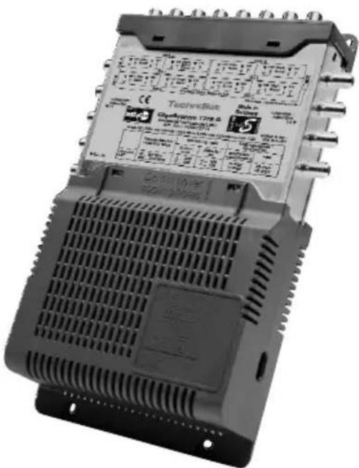
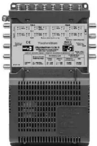
GigaSystem 17/8 G (Art.-No. 0000/3271)
This multi-switch is the basic unit of a distribution system. It distributes the signals from up to 16 satellite IF planes to 8 participants. The outputs are slope-equalized. The unit comes equipped with a powerful, efficient power supply unit.
The GigaSystem 17/8 G always delivers the 22kHz-control-signal at the inputs Option A / Pos. A / High-Band for further use of an available switch-LNB.
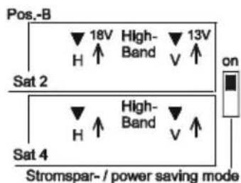
Additional the 17/8G has a power saving mode, which can be switched off.
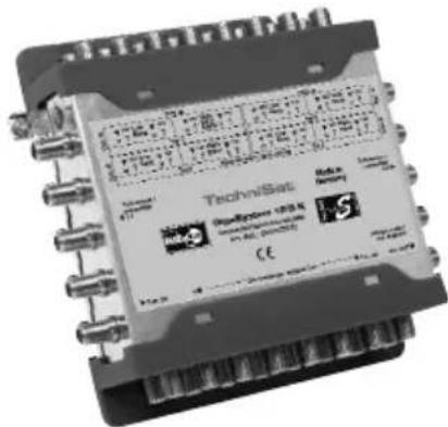
GigaSystem 17/8 K (Art.-No. 0000/3272)
This cascading unit for 8 participants works together with the basic unit (GigaSystem 17/8G). When used in conjunction with intermediate amplifiers, it can be connected in series up to four times, one behind the other. The power supply is drawn from the GigaSystem 17/8 G, and is passed through the 17/8K to all trunk lines without any internal interconnections.
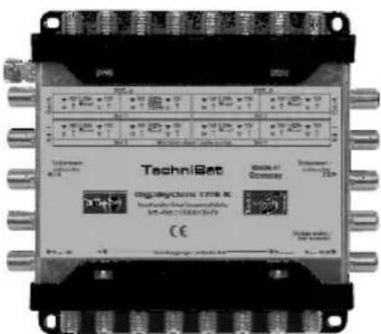
We offer additional equipment for the installation of bigger constructions. For further information, please refer to the installation guide of the individual devices.
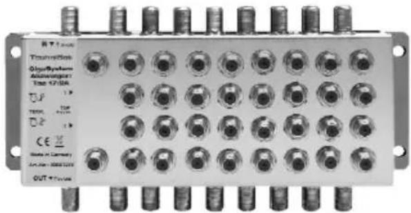
Active branch distributor 17/2A (Art. No. 0000/3270)
This system element allows you to distribute in one device the signals of a multiple trunk line to two multiple sub-trunks.
The trunk lines have almost no damping effect, and are permeable for direct current. The branch distributors provide slope rectification. The 17/2A can be cascaded up to six times to provide signals for the sub-distributions for individual floors in a high-rise building, or for several houses in a row or cluster of houses.
The device does not feed the trunks, and is it fed by the sub-trunks 1.
At the trunk output of the last 17/2A must be connected a 17/8G to feed the cascading units and the intermediate amplifiers of this multiple trunk as well as the LNB's.
natural_image
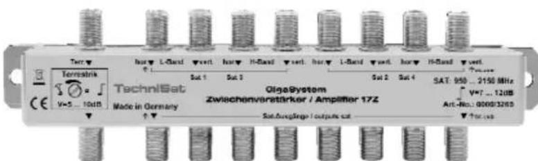
Front panel of a multi-pin electronic device with multiple ports and connectors (no visible text or symbols)Intermediate amplifier 17Z (Art. No. 0000/3269)
The amplification levels as well as the fixed slope rectification of this unit are specifically designed to compensate the damping caused by cables and/or components of 13dB at 2150MHz.
The amplification of the terrestrial path is adjustable.
It combines all horizontal and vertical trunk lines with each other by means of direct current (except SAT1, High Band); so that the DC-resistance of individual trunk lines is decreased.
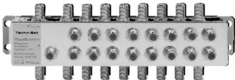
Passive distributor 17P (Art. No. 0000/3268)
This device has a maximum damping of 4dB and distributes the signals of the 16 satellite IF planes and of the terrestrial path to two outputs. One of the outputs provides direct current decoupling in order to prevent any mutual interference by the power supplies feeding in current.
natural_image
Front view of a TechniSec SignalSystem module with multiple ports and connectors (no visible text or symbols on the device body)4 Installation in buildings with one or two accommodation units
Assembly of small installations is simple, and does not require professional assistance.
Please note that the levels of the satellite signals fed into the system should be of approximately equal strength, this helps to ensure that the very good decoupling provided is not restricted. Consult your dealer if needed.
We recommend a star-shaped installation, based either in the attic or in the centre of the building. Without additional amplification, the cable length from LNB to antenna sockets should not exceed 230 feet. At such long distances use the cable CoaxSat2150 to connect to the socket.
If larger distribution installations are involved, cascading with distribution by floors has proven practical.
If possible, set up the installation using empty cable feed tubes. Since cables are very sensitive, you should arrange these as the end of the construction progress. If there are bends in the cable feed tubes or long distances to bypass, install the cable immediately.
Do not bend the cables too sharply. Do not use force, or try to stretch the cables too much.
Install the equipment while it is not connected to the main power supply.
Particularly where installations are fairly large, we recommend you check all cable for short circuits before fitting the contacts, as this will avoid a time-consuming search for faults later on.
Ensure that the cables coming from the LNB's are not crossed. For easy identification, we suggest you use MULTIMEDIA cable, and mark the appropriate ables with suitable coloured markers.
A terminal resistor may not be fitted to any input connections not used.
If you are looking for a particularly linear frequency graph for terrestrial distribution, you can insert a 75-Ohm terminal resistor on any outputs not used.
If you continue to use a switchable LNB, please ensure the voltage provided at the LNB is still adequate (greater than 16,5V for the horizontal planes; greater than 11,5V for the vertical planes)
The energy-saving setting of the 17/8G can only be switched on if you have not installed a cascading matrix ahead of it.
Please try to ensure that terrestrial signals fed in are all of approximately the same signal strength.
Use of a pre-amplifier for the terrestrial signal is not required.
4.1 Selecting the outdoor unit / LNB's
One will generally use four Quatro-LNB's.
If you want to use a remaining LNB or to transfer a special combination of polarization planes, please refer to chapter 5.1.
4.2 Cables and connectors
For connecting the LNB's to the multi-switch and to the components, it is recommended to use of multiple coax- 4 or 5 in a common cable jacket, e.g. MULTIMEDIA-Cable (Art. -No. 0001/3014)
For connecting the multi-switch to the antenna sockets, the use of Mini-Coax-Cable (Art. -No. 0001/3011) is recommended.
Due to the amplification provided by the units, you can use thin, flexible, easily handled cable types even with higher loss.
To install long stretches of cable connections to the antenna sockets, please use the low-loss coaxial cable CoaxSat 2150 (Art. -Nr 0002/3107) or (Art. -Nr 0001/3106).
For professional appliance, TechniSat recommends not to use F-connectors that need to be screwed on to the cable. For the home use you can apply above described connectors, if professional crimping tools are not available.
Buy cables and connectors at your specialist dealer. They are able to provide cut cables in quantity and can assist you with your questions!
Regarding connectors and cutting lengths refer to chapter 5.1
4.3 Antenna sockets
Participants can be connected to the system using TechniPro SV 500
(3-pin antenna sockets, Art. -Nr 0000/3075). This facilitates reception of terrestrial programs with no need for connections to be changed, and the equipment is protected from interference from other bands.
5 Installation of large-scale GigaSystem-distributions
Distribution installations for SMA and CATV (respectively terrestrial) signals) involving more than 40 participants should only be installed by professionals with an appropriate level of knowledge on interdependent parameters, and who have a selective antenna measuring and calibration unit available.
Large-scale installations are set up in a multiple trunk – star-shaped structure.
A large number of sub-distributions can be supplied by a main trunk line. This is necessary to ensure the insulation does not deteriorate to a level where the system becomes unusable (20dB, incl. Frequency response- and neighbouring reserves).
A few brief notes on functions, by way of explanation:
In the switching matrices, the signal is acquired by directional couplers, and then transported to the individual participant by means of MMIC switches via filters and amplifiers. Although this path ensures there is no loss of signal strength (damping) caused by the switching matrices, the level within the switching matrix is significantly lower in some sections. Therefore the input level of the switching matrix should not be less than 58dB V.
As the trunk lines present a high level of decoupling, you can practically eliminate any interference based on lack of insulation, as long as you follow the notes presented in this chapter.
5.1 Additional reference to LNB's, cables and wall-sockets

LNB's:
Switchable LNB's (Quatro Switch LNB's or Twin LNB's) should only be used if they are already available, only for single party installations and also only with SAT1 inputs (Option A / Position A, here the switching matrix provides 22 kHz for the High Band). The degradation in insulation consistent with the use of switchable LNB's does not affect single-party installations (using only a single 17/8G and a 17/8K).
In conjunction with SAT1, two Twin LNB's can only be used for two different orbital positions.
As far as the intention to receive two planes of a Low Band, this can also be achieved by using a Dual Output LNB or a TWIN LNB.
If you require only a single polarisation plane in the Low Band range, you can use a Single LNB for this. A polarisation plane in the High Band range can be received via a Single LNB only via the SAT1 connection.
Cable:
Table 1: Loss (dB/x metre) of suitable cable types
| Type CoaxSat 2 | 150 (100 dB) | Mini-, Multimediacable | ||||||
| dB at frequency/MHz 30 | 300 86 | 0 215 | 0 30 30 | 0 860 2 | 150 | |||
| 10 m | 0,3 | 1 | 1,8 | 3 | 0,5 | 1,5 | 2,5 | 4,2 |
| 20 m | 0,6 | 2 | 3,6 | 6 | 1 | 3 | 5 | 8,4 |
| 30 m | 0,9 | 3 | 5,4 | 9 | 1,5 | 4,5 | 7,5 | 12,6 |
| 40 m | 1,2 | 4 | 7,2 | 12 | 2 | 6 | 10 | 16,8 |
| 50 m | 1,5 | 5 | 9,0 | 15 | 2,5 | 7,5 | 12,5 | 21 |
| 60 m 1,8 6 10,8 18 | ||||||||
| 70 m 2,1 7 12,6 21 | ||||||||
| Loop resistance (core and shield)- For a single cable- For the 7 cables of a feed voltage | 0.35 Ohm/10m60 mOhm/10m | 0.56 Ohm/10m80 mOhm/10m | ||||||
Regarding selection of the cable see also chapter 4.2
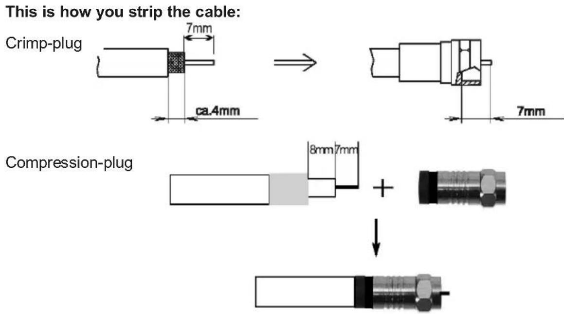
Antenna wall socket:
Table 2: Output levels of a SV-500 antenna socket
| Socket loss Level | minimuml commended maximum | |||
| Satellite range 2 dB 4 | 7 dBμV 58 dBμV 79 dBμV | |||
| FM 5 dB 50 dBμV 63 | dBμV 70 dBμV | |||
| analog terr. TV | VHF 4 dB/ UHF 3 dB | 55 dBμV | 63 dBμV | 70 dBμV |
| DVB-T | 40 dBμV | 50 dBμV | 70 dBμV | |
| DVB-C | 47 dBμV | 55 dBμV | 70 dBμV | |
The TechniPro SV 500 (3 jackets) provides access to the return channel at the TV socket (VHF/UHF). To separate the TV from the outward/return channel, you would have to install a BK 2-way distributor (Art. -Nr. 0000/3068) just behind the SV-500. In this case, please note the total loss of 8dB.
Table 3: Levels at output of an SVR 500 antenna socket
| Socket loss Level | minimum recommended maximum | |||
| Satellite range 2 dB | see to table 2 | |||
| FM 4 dB | ||||
| analog terr. TV 5 dB | ||||
| Return channel and TV 4 | dB 100 dBμV 110 dBμV 11 | 7 dBμV | ||
Built-in distributor cabinet:
For installation in stairways, particularly suited where distribution originates at the centre of the building, you should use a distributor cabinet that can be installed in or on the wall. When necessary, this cabinet also provides space for an additional intermediate amplifier or other devices.
The door should be locked with a built-in padlock
5.2 Planning
For large-scale installations a calculation of "coverage" is necessary. This means you must consider the following points unconditionally:
- Level
- Isolation
- Voltage drops
- Load of power supplies
Satellite range
Set up a construction plan showing all cable lengths involved
The switching matrices work essentially without any loss of signal strength; avoid levels above limits in the trunk lines. In the satellite range 75dBμV are recommended.
Write down the expected and the required levels at the inputs and outputs of the components see also: Technical data list and table 1.Please note: Where large-scale satellite distribution is involved, even minor errors or incorrect calculations can add up to major overall problems.
Avoid overloading the socket, and also avoid having the signal fall below the minimum required level for the socket, see Table 2. A minimum BER (Bit Error Rate) or the required C/N ratio (carrier-noise ratio) must be ensured at every point in the system.
Input signal range on receiver (regulation range): 44dBμV...84dBμV.
Set the gain as well as the use of cables in such a way that the transponder levels at the upper limit of the bandwidth do not fall below the minimum required level, which can be caused by a drop in the frequency response of the LNB's as well as the fact that equalisation in the cable loss does not quite achieve theoretical maximum levels. In reality though, can unfortunately levels here be as much as 10 dB lower than in the middle of the band.
Calculate whether the isolation is adequate. Each additional component added in series will reduce isolation by approx.4dB. Isolation should not be less than 20dB at the participant's end.
Estimate the effect of the voltage drop (reduced voltage) to be expected in the various components. The voltage must still be adequate for the LNB's as well as for any accessory components (horizontal >16.5V, vertical >11.5V).
Check the power load of the individual power supplies. The power consumption values can be found in the technical data list.
Add in some reserve capacity when making your calculations; this improves liability and longevity of your system.
If you are also utilising the return path, the signals of the individual participants (with a reserve of 5 dB) must be within the input range of the head end tuner (generally 40...75dBμV).
Terrestrial reception
The simplest solution is to use a terrestrial broadband antenna. In this case you must pay particular attention that the FM signals are not too strong.
If the signals of the various bands are received from different directions, it is recommend you use several antennae, connected by a terrestrial combiner (filter). To some extent, different signal strengths can be compensated by using different antenna sizes.
The signal path is designed to be fairly resistant against any intermodulation (output levels at 60 dB IMA3: 102 dBμV, in accordance with DIN 45004 B). However, if you are simultaneously distributing FM, VHF or a cable signal as well as UHF, you may encounter cross modulation interference (Moiré). In this case you should consider the following
Use a pre-amplifier (naturally with a low noise level and resistant to overload) only if there are no high-strength signals in the range (even if you otherwise have weak input signals).
Analogue TV signals of < 60 dBμV suffer from significant noise, particularly in larger installations, and are not suitable for this type of distribution. Incoming DVB-T signals with strength of 45 dBμV can still be distributed.
In case some of the participants are only interested in receiving a „basic“ package of terrestrial signals, please branch off the combined terrestrial incoming signal either before it reaches the first switching matrix, or in the middle of the cascaded distribution. If necessary, you can insert a preamplifier at this stage (without, however, exceeding the maximum input level possible).
If you require only a very small number of connections for this „basic package“, you can also implement it by splitting one branch off a switching matrix (benefit: utilisation of the gain provided by the 17/X system).
5.3 Installation
Mark each cable at both ends with the apartment and/or room number, and note the number of the switching matrix in the socket.
As far as possible, install the cables as single unbroken sections. Faulty F to F-connector jacks inserted along the way can cause interference and errors.
If you are installing very long sections of cable to the individual participants (> 60 m), you should install a double wall socket (as open for future use) after about 3/4 of the total length. So that you can, if necessary, open up the cable and install an intermediate amplifier at a later stage.
For screw-type connectors, use socket wrench Art. No. 0000/3407. Do not over-tighten the nuts of the F-connectors.
Do not use quick-fastening (snap-on) F-connectors.
If you are not sure as to where a particular cable leads, fit a 75-Ohm resistor to what you consider to be the other end, and measure the resistance.
If some participants are not to receive the satellite signals, simply insert a DC block (Art. No. 0000/3405) in their supply lines
You can also connect this participant to a another participant by means of a 2-way splitter, that does not provide a direct current path at this point.
5.4 Calibration
Checking the satellite range
Check the output signals provided by the LNB's; they must be linear over the entire frequency (< 5 dB fall-off). Any differences caused by the power flux density of the satellite can be at least partly compensated by using different sizes of satellite dish antennas, and/or using pre-amplifiers.
A short circuit in the LNB connections or trunk lines will be indicated by the both LED's of the 17/8G (visible through the ventilation slits), please refer to chapter 7.
Make a note of the levels and quality. BER (Bit error rate) for digital signals, or S/N (Signal / Noise ratio) for analogue signals of selected transponders at the upper end of the bands.
If possible, when you have completed adjusting the levels for the installation, make printouts of the levels measured at the individual participant sockets. This will greatly facilitate any search for problems that may become necessary at a later stage.
Checking the terrestrial signals
If strong and weak signals are received from different directions, try to make the reception of the strong signals weaker by adjusting the position of the antenna.
If all the signals are received from the same direction, you can use either one or more good trap circuits to equalise the signal strengths (e.g. TSF 2169/2, Art. No 0000/6042) or you use channel filters.
With knowledge of the band allocations, set the trap circuits using a professional antenna calibration tool in such a way that the weaker signals are immersed in the noise to a slightly greater extent.
Where an FM signal is being fed into the terrestrial combiner, it may be necessary to use an adjustable damping joint.
If a very linear frequency response distribution of terrestrial means is needed, terminate unused outputs of the participants with a 75?-termination.
To avoid interference from the satellite reception range, it may be advisable to switch off the satellite receiver while receiving weak terrestrial signals.
Checking on the return path
Feed the test channel of the modem into the system at the point of the participant located furthest from the distribution installation, and measure the signal arriving at the headend. You must also consider the different losses caused by the switching matrices and by any accessory components.
5.5 Options for combinations with other TechniSat multi-switch systems
TechniSwitch 5/8 switching matrices may be used only in sub-distributions (see Point 6.2) and then only where the maximum current feeding the receiver (generally 400mA) will not be exceeded. Benefit: Energy savings.
Please note that in this case the terrestrial signal is not continuously available.
TechniSystem 5/8 units: 5/2A units with sub-distributions fitted behind the unit may be used at any location.
GigaSwitch 9/8 units: 9/2A units with sub-distributions fitted behind the unit may be used at any location.
Additional information can be found at: www.technisat.com. Please contact our customer service for detailed questions.
5.6 Switching options with and without DiSEqC
DiSEqCTM (Digital Satellite Equipment Control) is a bus system developed by Philips in co-operation with Eutelsat, which is used here to select from more than 4 polarisation planes (from more than 4 inputs).
This is how the set-top box selects the individual inputs:
Digital commands or analogue commands
A DiSEqC bus monitor looped in for the test displays this „hex“ command.
If you are using old analogue reception equipment not equipped with DiSEqC, only SAT1 can be received. Only very few old analogue receivers also transmit the Simple DiSEqC tone burst. The 17/8 can also process this signal, the burst switches to SAT2.

6 Examples of installations
6.1 Equipment for 16 participants
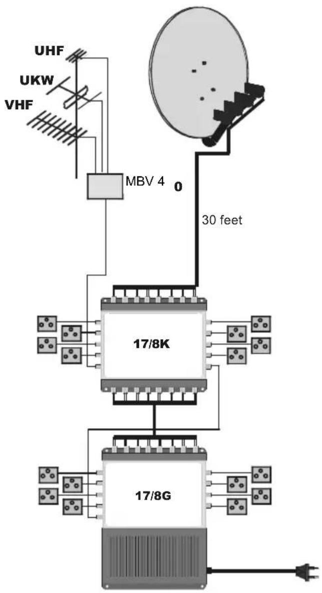
flowchart
graph TD
    A["17/8K Module"] --> B["17/8G Module"]
    B --> C["MBV 4"]
    C --> D["30 feet Satellite Array"]
    D --> E["UHF"]
    D --> F["UKW"]
    D --> G["VHF"]
    B --> H["Grid of Sensors"]
    B --> I["Grid of Sensors"]
    style A fill:#f9f,stroke:#333
    style B fill:#ccf,stroke:#333
    style C fill:#cfc,stroke:#333
    style D fill:#fcc,stroke:#333
    style E fill:#ffc,stroke:#333
    style F fill:#fcc,stroke:#333
    style G fill:#ffc,stroke:#333
    style H fill:#cff,stroke:#333
plan of levels
| LNB 950 MHz 2150MHz | |
| level at LNB output | 75 dBμV 75 dBμV |
| 950 MHz 2150MHz | |
| level at 17/8K input | 73 dBμV 71 dBμV |
| level at SV 500 | 69 dBμV 63 dBμV |
| 950 MHz 2150 MHz | |
| level at 17/8K input | 70 dBμV 66 dBμV |
| level at SV 500 | 66 dBμV 58 dBμV |
6.2 Apartment buildings with 40 participants on 5 floors
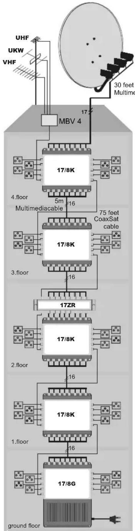
flowchart
graph TD
    A["ground floor"] --> B["17/8G"]
    B --> C["17/8K"]
    C --> D["17ZR"]
    D --> E["3.floor"]
    E --> F["17/8K"]
    F --> G["4.floor Multimediacable"]
    G --> H["5m"]
    H --> I["17/8K"]
    I --> J["3.floor"]
    J --> K["17/8K"]
    K --> L["UHF"]
    K --> M["UKW"]
    K --> N["VHF"]
    K --> O["30 feet Multime"]
    style A fill:#f9f,stroke:#333
    style B fill:#ccf,stroke:#333
    style C fill:#cfc,stroke:#333
    style D fill:#fcc,stroke:#333
    style E fill:#cff,stroke:#333
    style F fill:#ffc,stroke:#333
    style G fill:#cfc,stroke:#333
    style H fill:#fcc,stroke:#333
    style I fill:#cfc,stroke:#333
    style J fill:#fcc,stroke:#333
    style K fill:#cfc,stroke:#333
    style L fill:#fcc,stroke:#333
    style M fill:#cfc,stroke:#333
Calculation of range of coverage:
- cascade with distribution by floors
- example for sub distribution in longer installations (in this case you need to use 17/2A instead of the LNB's)
| level isolation voltage current | |||
| @2,15 GHz (dB) (V) on the spot (mA) | |||
| LNB 70 45 17,2 800 | |||
| 17/8K-input | 62 | 45^1) | 17,3 930 | |
| socket | 54 35 |
| 17/8K-input | 56 42 17,4 | 1060 | |
| socket | 48 35 |
| 17ZR | 54 | 38 | 17,5 | 1240 |
| 17/8K | 67 | 37 17,6 | 1370 | |
| socket | 59 | 33 |
| 17/8K-input | 61 36 17,8 | 1500 | |
| socket | 53 32 |
| 17/8K-input | 55 35 | 18V | 1570 | |
| socket | 47 | 32^2) |
1) Isolation of the 17/8K, for calculation purposes without consideration of the LNB's
2) Together with the 25dB of the LNB's at best there will be arising approx. 24dB isolation. If you add two 17/2AR and one 17ZR in a longer installation (see 6.2), the isolation increase to worst case B => That's just enough to operate.
6.3 Installation utilising a line

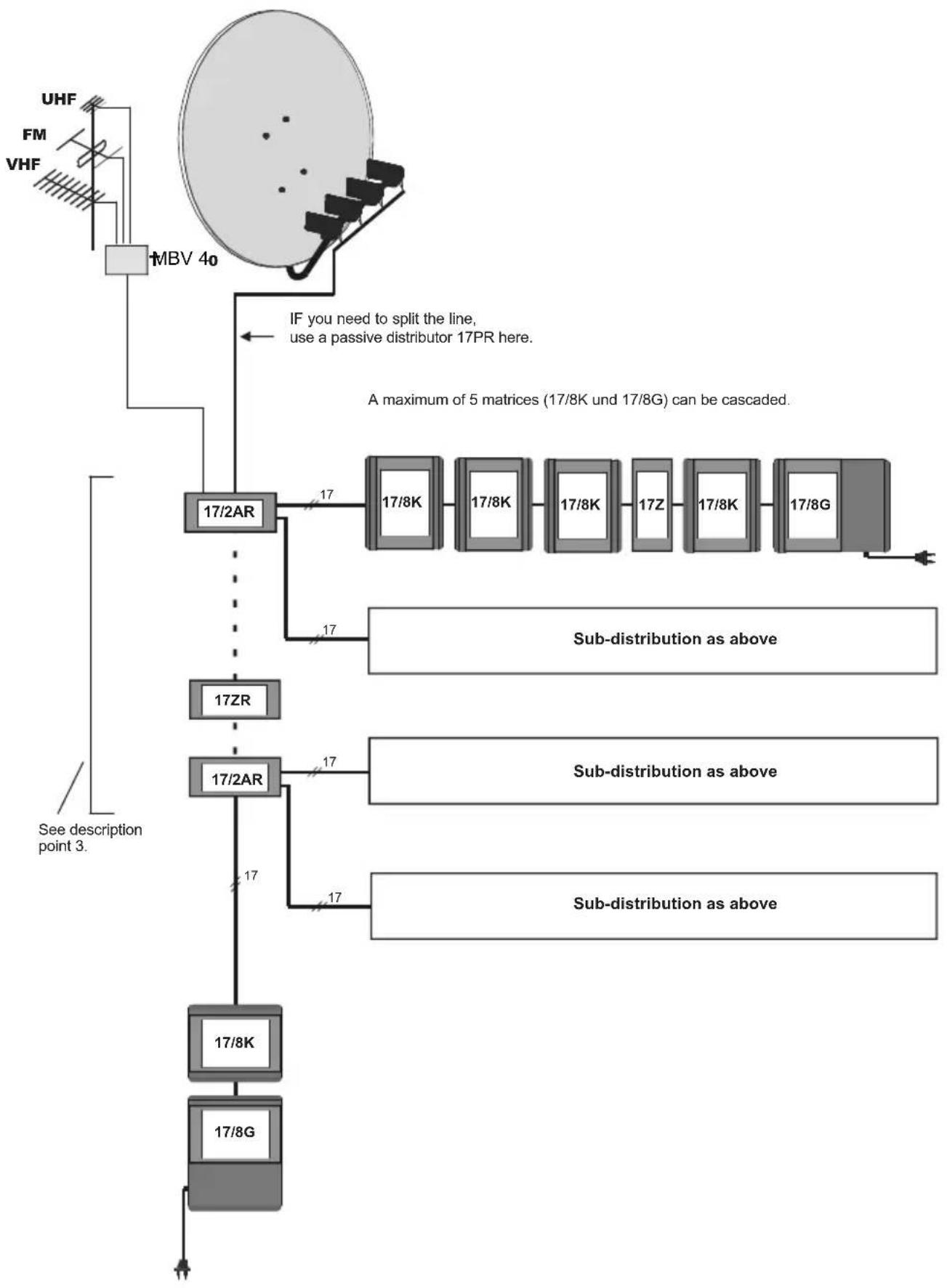
flowchart
graph TD
    A["UHF"] --> B["FB"]
    C["FM"] --> B
    D["VHF"] --> B
    B --> E["MBV 40"]
    E --> F["17/2AR"]
    F --> G["17/8K"]
    F --> H["17/8K"]
    F --> I["17/8K"]
    F --> J["17Z"]
    F --> K["17/8K"]
    F --> L["17/8G"]
    M["A maximum of 5 matrices (17/8K und 17/8G) can be cascaded."] --> N["Sub-distribution as above"]
    O["See description point 3."] --> P["17ZR"]
    Q["17/2AR"] --> R["17/8K"]
    Q --> S["17/8G"]
    T["17/2AR"] --> U["17/8K"]
    T --> V["17/8G"]
    W["17/2AR"] --> X["17/8K"]
    W --> Y["17/8G"]
6.4 Installation in high-rise buildings
(24 participants/floor, 864 participants combined, 138 components)
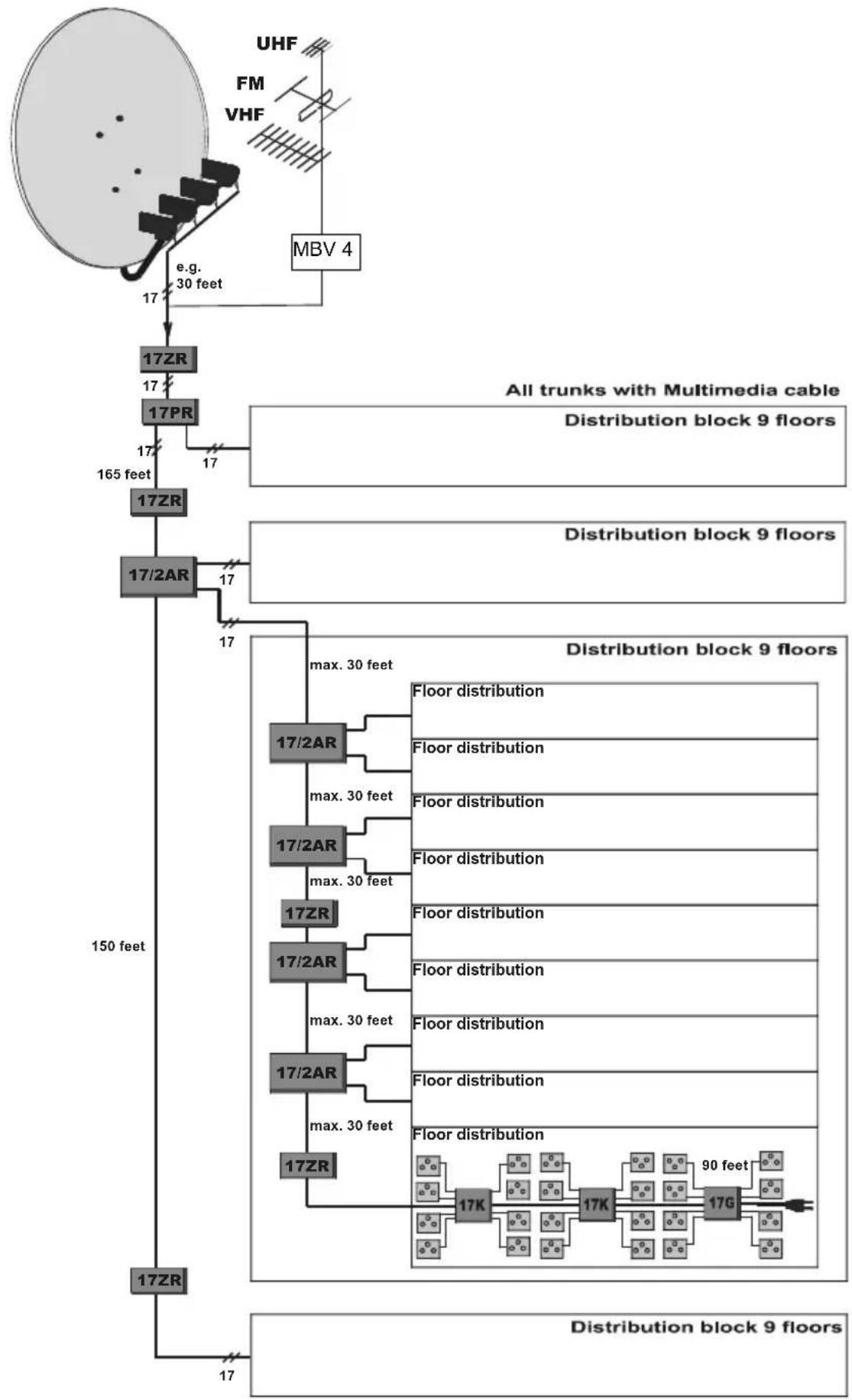
flowchart
graph TD
    A["17ZR"] --> B["17ZR"]
    B --> C["17PR"]
    C --> D["17ZR"]
    D --> E["17/2AR"]
    E --> F["17ZR"]
    F --> G["17ZR"]
    G --> H["17ZR"]
    H --> I["17ZR"]

    J["MBV 4"] --> K["FM VHF"]
    K --> L["UHF"]

    M["All trunks with Multimedia cable"] --> N["Distribution block 9 floors"]
    N --> O["165 feet"]
    P["Distribution block 9 floors"] --> Q["Distribution block 9 floors"]

    R["150 feet"] --> S["Distribution block 9 floors"]
    S --> T["Floor distribution"]
    S --> U["Floor distribution"]
    S --> V["Floor distribution"]
    S --> W["Floor distribution"]
    S --> X["Floor distribution"]
    S --> Y["Floor distribution"]
    S --> Z["Floor distribution"]
    S --> AA["Floor distribution"]
    S --> AB["Floor distribution"]
    S --> AC["Floor distribution"]
    S --> AD["Floor distribution"]
    S --> AE["Floor distribution"]
    S --> AF["Floor distribution"]
    S --> AG["Floor distribution"]
    S --> AH["Floor distribution"]
    S --> AI["Floor distribution"]
    S --> AJ["Floor distribution"]
    S --> AK["Floor distribution"]
    S --> AL["Floor distribution"]
    S --> AM["Floor distribution"]
    S --> AN["Floor distribution"]
    S --> AO["Floor distribution"]
    S --> AP["Floor distribution"]
    S --> AQ["Floor distribution"]
    S --> AR["Floor distribution"]
    S --> AS["Floor distribution"]
    S --> AT["Floor distribution"]
    S --> AU["Floor distribution"]
    S --> AV["Floor distribution"]
    S --> AW["Floor distribution"]
    S --> AX["Floor distribution"]
    S --> AY["Floor distribution"]
    S --> AZ["Floor distribution"]
    S --> BA["Floor distribution"]
    S --> BB["Floor distribution"]
    S --> BC["Floor distribution"]
    S --> BD["Floor distribution"]
    S --> BE["Floor distribution"]
    S --> BF["Floor distribution"]
    S --> BG["Floor distribution"]
    S --> BH["Floor distribution"]
    S --> BI["Floor distribution"]
    S --> BJ["Floor distribution"]
    S --> BK["Floor distribution"]
    S --> BL["Floor distribution"]
    S --> BM["Floor distribution"]
    S --> BN["Floor distribution"]
    S --> BO["Floor distribution"]
    S --> BP["Floor distribution"]
    S --> BQ["Floor distribution"]
    S --> BR["Floor distribution"]
7 Trouble-shouting guide

| Problem Possible causes Solution | ||
| No reception on any polarisation planes | Antenna not positioned correctly | Use a calibration instrument or a receiver to check the signals at a LNB and then at a distributor. |
| Receiver incorrectly set | Check that the settings of the receiving equipment are correct. | |
| No operating current for LNB or auxiliary equipment | Check the voltage fed into the LNB from the 17/8G, by disconnecting the appropriate cable, and measuring it using a needle stuck into the socket. | |
| Still no reception, control LED on main adapter blinking, no operating current | Particularly with large-scale installations, there is an increased likelihood of a short-circuit in the trunk co-axial cables, somewhere between the core lead and the shielding mesh (copper thread), or this may develop (e.g. through heat). | green LED:- flashes, if 18V are at the “horizontal Sat-“ Inputs of the 17/8G- is blinking or switched off, if there is a short on 18V or an overload (on 18V and 13V). yellow LED:- flashes, if 13V are at the “vertical Sat-“ Inputs of the 17/8G- is switched off or of a darker light, if you have a short or overload at 13V. |
| Power supply is overloaded (I, max >2,2A) | Check your calculation regarding the load of the power supplies ? If o.k, disconnect individual units of the installation by disconnecting the trunk line connectors, in order to identify the location of the short circuit. Be careful not to cause other short circuits while you are doing this. The exact location can be pinpointed by measuring the resistance. | |
| Operating voltage (LNB voltage on trunk lines) too low | On long cable stretches, the drop-off in voltage via cable or components may be too great. | In large-scale installations, check your voltage drop calculation.Install an additional power supply unit. |
| No reception or incorrect program on individual polarization planes | LNB connections or trunk lines may have been switched around, or core lead is too short.Take note that direct current feed is not provided at all outputs of all Quattro LNB's | - Check both the connectors and the allocations.- Check the signal directly on the LNB connection.- Note: Check reception of several satellites to determine possible differences required in LNB feed. |
| A switchable LNB is not working | Not receiving 22kHz for the High Band or switching voltage too low. | - Switchable LNB can only be connected to SAT1 (17/8 GR and KR do not have this function).- Connect a DiSEqC-Indicator instead of a LNB. Check lengths of cables. |
| Missing transponders or weak signals at upper end of band | Signal too weak overall and/or significant negative slopes, caused by long cables and many components. | - Check the signal directly at the LNB, and then at another distribution point.- Check your satellite level calculation, if necessary install a 17ZR.- Only in large installations: Have you casca-ded too far? Check isolation calculation. |
| Individual distributors not working | LNB current and/or switching criteria of the receiver. | - Try connecting the receiving equipment to a different distributor.- Attention! Every receiver provides operating current to its distributor.-Use an indicator to check the receiver voltage as well as the switching criteria. |
| Moiré in terrestrial analogue television picture, or no program or „blocks“ on DVB-C or DVB-T | Input level too high, or incorrect setting of the terrestrial amplifier in the distribution chain. | - Measure and check your terrestrial level calculation, adjust levels.- Try bridging the existing 17ZR. |
| Noise in terrestrial analogue television picture, or no program or „blocks“ on DVB-C or DVB-T | Input levels too low, or incorrect setting of terrestrial amplifiers in distribution chain. | - See Paragraph 5.2. |
| „Humming bars“ in terrestrial analogue television picture | Grounding of individual components has been made to different potentials (humming loop). | - Initially on a trial basis, try to remove individual (subordinated) grounding points.- This rare effect can also be caused by auxiliary equipment with protective contacts connected to the receiver, or by other grounded reception antenna. |
8 Technical data GigaSystem 17/X (guaranteed parameters)
| Switching matrices | ||||
| Model | GigaSystem17/8 G GigaSystem17/8 K | |||
| Application for 8 participants for 8 participants | ||||
| Terr:47..862GHz,Sat: 0,95..2,15GHz Terr. Sat. Terr. Sat. | ||||
| Trunk line gain -2 ... -3dB -2 ... -4dB | ||||
| Slope correction none | ||||
| Tap gain: Corresponds to participant's gain in switching matrices | -4 ... -1dB | -2 ... +1dB | 1 ... 4dB -2 ... +1dB | |
| Slope correction fixed correction | ||||
| Return loss Trunks | 10dB | |||
| Taps | 8dB | |||
| Isolation Trunks 2) | 45dB | |||
| Taps | 35dB | |||
| Input level recommended maximum | 72 dBμV 3) | 70 dBμV 4) | 75 dBμV 3) | As for17/8G |
| 80 dBμV | 85 dBμV | 85 dBμV | ||
| Power supply for unit for LNB's | Power supply 18V, 13V total <2,2A, (overload & short-circuit protected) 17/8G: Standby (Terraktiv) <3W | feed from 17/8G bzw. GR | ||
| 18V, 13V, High-Band SAT1 with 22kHz (only for 17/8 G und K) | ||||
| DC resistance of unit for one voltage | <100mOhm (one line has 300mOhm) | |||
| Power consumption from power supply 3) from receiver | 70mA (from 18V) | 130mA (from 18V) | ||
| 40mA, max. 240mA (current pool) | ||||
| Control via receivers | DiSEqC 1.0 or higher, „Mini“-DiSEqC (receives only SAT1 und 2) or 11,5V ... 14V/16V ... 19V a. 0/22kHz, USS >0,25V (only SAT1) | |||
| Screening level | in accordance with EN50083-2/A1 and TechniSelect S | |||
| Ambient conditions | -25 ... +55°C, overvoltage protection inputs, outputs < 5kV | |||
| Dimensions: L x W x H, weight | 275 x 175 x 56; 1kg | 154 x 175 x 48; 0,8kg | ||
| Article number 0000/3271 | 0000/3272 | |||
2) All other trunk lines have a signal.
| Accessories | ||||||
| Model | Intermediate amplifier 17Z | Active branch distributor17/2A | Passive distributor 17P | |||
| Application | Amplification, when the level is dropped down | spared branching of two side trunks | signal splitting | |||
| Terr:47..862GHz,Sat: 0,95..2,15GHz | Terr. Sat. | Terr. Sat. T | Terr. | Sat. | ||
| Trunk line gain | 5 ... 10dB, adjustable | 7 ... 12dB | -1.2dB -1 ... | -1.5dB | ||
| Slope correction fixed correction none | ||||||
| Tap gain Corresponds to participant's gain in switching matrices | 5dB, adjustable | 3 ... 6 dB | -4dB -4dB | |||
| Slope correction | adjustable | fixed correction | none | |||
| Return loss TrunksTaps | 10dB 14dB | 8dB | ||||
| 10dB | ||||||
| Isolation Trunks 2)Taps | 40dB | 50dB, widely cascadable | 45dB | |||
| 45dB | ||||||
| Return path loss Trunk5 ... 30 MHz, only R-types Taps | 1.5dB | 2dB | 4.5dB | |||
| 11dB | ||||||
| Input level recommended maximum | 58 dBμV | 5 dBμV 65 | dBμV 70 | dBμV | passive | |
| 75 dBμV | 70 dBμV | 75 dBμV | 85 dBμV | |||
| Power supply for unitfor LNB's | via the trunk lines | from a 17/8G-opower supply in the side trunks | not needed, passive | |||
| from a unit with power supply in the main trunk | via one direct current path | |||||
| DC resistance of unit for one voltage | < 50mOhm (one line has 130mOhm) | < 50mOhm | ||||
| Power consumption from powersupply 3) from receiver | 180mA (18V),120mA (13V) | 300mA (von 18V) | ||||
| Screening level | in accordance with EN50083-2/A1 and TechniSelect S | |||||
| Ambient conditions | -25 ... +55°C, overvoltage protection inputs, outputs < 5kV | |||||
| Dimensions: L x W x H, weight | 212 x 58 x 45; 0,7kg | 212 x 105 x 45; 1,3kg | 212 x 69 x 45; 0,9kg | |||
| Article number | 0000/3269 | 0000/3270 | 0000/3268 | |||
3) Related to broadband cable signal in BC grid (36 TV signals, 14 FM programmes), CTB (72 dB) / CSQ (69 dB), with terrestrial reception individual channels are usually stronger, this is acceptable as long as they remain <90 dBμV.
4) in accordance with EN 50083-3: IMA3 35 dB
Calculation hints for calculating the “range of coverage”

| Loss (dB) Loop | resistance Fall-off voltage | ||
| 20mMulti-media cable 5 | ... 8,4 | 150 mOhm 1) | 0,15 V (at I = 1A) |
| Trunk 17/8K mit5m Multi-media cable | 4 ... 6 | 250 mOhm 1),2) | 0,5V (at I = 2A) |
| Distributor 17/8XX with25m CoaxSat2150 and Socket | 8,5 ... 9 1 Ohm | 0,25V (at I =25mA | |
1) in the trunk, because of parallel switching via direct current (each of 7 individual co-axial cables) this is less than that of a single co-axial cable
2) Average value, a single line has 530 mOhm (important for installations with no direct current connection of the trunk lines (see Paragraph.3).
Your unit carries the CE logo, and complies with all relevant EU standards. Subject to change without notice, subject to printing errors. Correct as at 11/11 TechniSat and GigSystem are registered trademarks of
D-54541 Daun, Germany
www.technisat.de
- Installation instructions
- TechniSat
- GigaSystem 17/8G, 17/8K
- Inhalt
- Application
- Safety instructions
- GigaSystem 17/X components
- GigaSystem 17/8 G (Art.-No. 0000/3271)
- GigaSystem 17/8 K (Art.-No. 0000/3272)
- Active branch distributor 17/2A (Art. No. 0000/3270)
- Intermediate amplifier 17Z (Art. No. 0000/3269)
- Passive distributor 17P (Art. No. 0000/3268)
- Installation in buildings with one or two accommodation units
- Assembly of small installations is simple, and does not require professional assistance.
- Selecting the outdoor unit / LNB's
- Cables and connectors
- Antenna sockets
- Installation of large-scale GigaSystem-distributions
- Additional reference to LNB's, cables and wall-sockets
- LNB's:
- Cable:
- Antenna wall socket:
- Built-in distributor cabinet:
- Planning
- Satellite range
- Terrestrial reception
- Installation
- Calibration
- Checking the satellite range
- Checking the terrestrial signals
- Checking on the return path
- Options for combinations with other TechniSat multi-switch systems
- Additional information can be found at: www.technisat.com. Please contact our customer service for detailed questions.
- Switching options with and without DiSEqC
- Examples of installations
- Equipment for 16 participants
- Apartment buildings with 40 participants on 5 floors
- Calculation of range of coverage:
- Installation utilising a line
- Installation in high-rise buildings
- Trouble-shouting guide
- Calculation hints for calculating the “range of coverage”
Brand : TECHNISAT
Model : GigaSystem 17/8 K
Category : Uncategorized