
Quasar CP-6302 - Security Camera FLIR - Free user manual and instructions
Find the device manual for free Quasar CP-6302 FLIR in PDF.


| Product Type | IP Security Camera |
| Brand | FLIR |
| Model | Quasar CP-6302 |
| Video Resolution | 1920 x 1080 pixels (Full HD) |
| Night Vision | Yes, up to 30 meters with IR LEDs |
| Viewing Angle | 90° (horizontal) |
| Video Compression | H.264, MJPEG |
| Power Supply | PoE (802.3af) or 12V DC adapter |
| Power Consumption | Max. 7 W |
| Dimensions (L x W x H) | 76 x 76 x 155 mm |
| Weight | 480 g |
| Protection Rating | IP67 (dust and water resistant) |
| Operating Temperature | -40°C to 60°C |
| Main Functions | Motion detection, continuous video streaming, recording on SD card or NAS |
| Connectivity | Ethernet 10/100, Wi-Fi not available |
| Storage | MicroSD card slot (up to 128 GB) |
| Security | SSL/TLS encryption, password authentication |
| Maintenance and Cleaning | Clean the housing and lens with a soft, dry cloth |
| Spare Parts and Repairability | No user-serviceable parts; repair by certified professional |
| Box Contents | Camera, mounting bracket, screw kit, power adapter (depending on version), quick start guide |
Frequently Asked Questions - Quasar CP-6302 FLIR
User questions about Quasar CP-6302 FLIR
0 question about this device. Answer the ones you know or ask your own.
Ask a new question about this device
Download the instructions for your Security Camera in PDF format for free! Find your manual Quasar CP-6302 - FLIR and take your electronic device back in hand. On this page are published all the documents necessary for the use of your device. Quasar CP-6302 by FLIR.
USER MANUAL Quasar CP-6302 FLIR
© 2017 FLIR Systems, Inc. All rights reserved worldwide. No parts of this manual, in whole or in part, may be copied, photocopied, translated, or transmitted to any electronic medium or machine readable form without the prior written permission of FLIR Systems, Inc.
Names and marks appearing on the products herein are either registered trademarks or trademarks of FLIR Systems, Inc. and/or its subsidiaries. All other trademarks, trade names, or company names referenced herein are used for identification only and are the property of their respective owners. This product is protected by patents, design patents, patents pending, or design patents pending. The contents of this document are subject to change.
FLIR Systems, Inc.
6769 Hollister Avenue
Goleta, California 93117
USA
Phone: 888.747.FLIR (888.747.3547)
International: +1.805.964.9797
For technical assistance, please call us at +1.888.388.3577 or visit the Service & Support page at www.flir.com/security.
Important Instructions and Notices to the User:
Modification of this device without the express authorization of FLIR Commercial Systems, Inc. may void the user's authority under FCC rules to operate this device.
Proper Disposal of Electrical and Electronic Equipment (EEE)

The European Union (EU) has enacted Waste Electrical and Electronic Equipment Directive 2012/19/EU (WEEE), which aims to prevent EEE waste from arising; to encourage reuse, recycling, and recovery of EEE waste; and to promote environmental responsibility.
In accordance with these regulations, all EEE products labeled with the “crossed out wheeled bin” either on the product itself or in the product literature must not be
disposed of in regular rubbish bins, mixed with regular household or other commercial waste, or by other regular municipal waste collection means. Instead, and in order to prevent possible harm to the environment or human health, all EEE products (including any cables that came with the product) should be responsibly discarded or recycled.
To identify a responsible disposal method nearby, please contact the local waste collection or recycling service, the original place of purchase or product supplier, or the responsible government authority in the area. Business users should contact their supplier or refer to their purchase contract.
Document History
Version
Ver. 1
Date
September 7, 2017
Comment
Initial FLIR release
FLIR
Table of Contents
- Document Scope and Purpose .... 1
- Installation 7
2.1 Waterproofing the Camera Cables 7
2.2 Mounting the Camera 8
2.2.1 Ceiling Mount 8
2.2.2 Pole Mount 12
2.2.3 Corner Mount 15
2.2.4 Wall Mount 18
2.2.5 Mini-Pendant Mount 22
FLIR
1 Document Scope and Purpose
The purpose of this document is to provide instructions and installation procedures for physically connecting the CP-6302 IR PTZ camera. After completing the physical installation, additional setup and configurations are required before video analysis and detection can commence.

Note:
This document is intended for use by technical users who have a basic understanding of CCTV camera/video equipment and LAN/WAN network connections.
Remarque:
Installation must follow safety, standards, and electrical codes as well as the laws that apply where the units are being installed.
Avertissement:
Users of FLIR products accept full responsibility for ensuring the suitability and considering the role of the product detection capabilities and their limitation as they apply to their unique site requirements.
FLIR Systems, Inc. and its agents make no guarantees or warranties to the suitability for the users' intended use. FLIR Systems, Inc. accepts no responsibility for improper use or incomplete security and safety measures.
Failure in part or in whole of the installer, owner, or user in any way to follow the prescribed procedures or to heed WARNINGS and CAUTIONS shall absolve FLIR and its agents from any resulting liability.
Specifications and information in this guide are subject to change without notice.
A Warning is a precautionary message that indicates a procedure or condition where there are potential hazards of personal injury or death.
A Caution is a precautionary message that indicates a procedure or condition where there are potential hazards of permanent damage to the equipment and or loss of data.
A Note is useful information to prevent problems, help with successful installation, or to provide additional understanding of the products and installation.
A Tip is information and best practices that are useful or provide some benefit for installation and use of FLIR products.
General Cautions and Warnings
This section contains information that indicates a procedure or condition where there are potential hazards.
SAVE ALL SAFETY AND OPERATING INSTRUCTIONS FOR FUTURE USE.
Although the unit is designed and manufactured in compliance with all applicable safety standards, certain hazards are present during the installation of this equipment.
To help ensure safety and to help reduce risk of injury or damage, observe the following:
- The unit's cover is an essential part of the product. Do not open or remove it.
- Never operate the unit without the cover in place. Operating the unit without the cover poses a risk of fire and shock hazards.
- Do not disassemble the unit or remove screws. There are no user serviceable parts inside the unit.
• Only qualified trained personnel should service and repair this equipment. - Observe local codes and laws and ensure that installation and operation are in accordance with fire, security and safety standards.
Avertissement:
- Do not drop the camera or subject it to physical shock.
- Do not touch sensor modules with fingers. If cleaning is necessary, use a clean cloth with a bit of ethanol and wipe it gently. If the camera will not be used for an extended period of time, put on the lens cap to protect the sensor from dirt.
- Do not aim the camera lens at strong light, such as the sun or an incandescent lamp, which can seriously damage the camera.
- Make sure that the surface of the sensor is not exposed to a laser beam, which could burn out the sensor.
- If the camera will be fixed to a ceiling, verify that the ceiling can support more than 23 newtons (23-N) of gravity, or over three times the camera's weight.
• The camera should be packed in its original packing if it is reshipped.

Caution:
To avoid damage from overheating or unit failure, assure that there is sufficient temperature regulation to support the unit's requirements (cooling/heating). Operating temperature should be kept within the range indicated in the Technical Specifications section.
Attention:
There are several requirements that should be properly addressed prior to installation at the site. The following specifications are requirements for proper installation and operation of the unit:
- Ambient Environment Conditions: Avoid positioning the unit near heaters or heating system outputs. Avoid exposure to direct sunlight. Use proper maintenance to ensure that the unit is free from dust, dirt, smoke, particles, chemicals, smoke, water or water condensation, and exposure to EMI.
- Accessibility: The location used should allow easy access to unit connections and cables.
- Safety: Cables and electrical cords should be routed in a manner that prevents safety hazards, such as from tripping, wire fraying, overheating, etc. Ensure that nothing rests on the unit's cables or power cords.
- Ample Air Circulation: Leave enough space around the unit to allow free air circulation.
- Cabling Considerations: Units should be placed in locations that are optimal for the type of video cabling used between the unit and the cameras and external devices. Using a cable longer than the manufacturer's specifications for optimal video signal may result in degradation of color and video parameters.
- Physical Security: The unit provides threat detection for physical security systems. In order to ensure that the unit cannot be disabled or tampered with, the system should be installed with security measures regarding physical access by trusted and un-trusted parties.
- Network Security: The unit transmits over IP to security personnel for video surveillance. Proper network security measures should be in place to assure networks remain operating and free from malicious interference. Install the unit on the backbone of a trusted network.
- Electrostatic Safeguards: The unit and other equipment connected to it (relay outputs, alarm inputs, racks, carpeting, etc.) shall be properly grounded to prevent electrostatic discharge.
The physical installation of the unit is the first phase of making the unit operational in a security plan. The goal is to physically place the unit, connect it to other devices in the system, and to establish network connectivity. When finished with the physical installation, complete the second phase of installation, which is the setup and configuration of the unit.
FLIR
2 Installation
This camera is designed for outdoor installation. Observe the following installation recommendations:
• Always use weatherproof equipment, such as boxes, receptacles, connectors, etc.
- For electrical wiring, use the properly rated sheathed cables for conditions to which the cable will be exposed (for example, moisture, heat, UV, physical requirements, etc.).
- Plan ahead to determine where to install infrastructure weatherproof equipment. Whenever possible, ground components to an outdoor ground.
- Use best security practices to design and maintain secured camera access, communications infrastructure, tamper-proof outdoor boxes, etc.
• All electrical work must be performed in accordance with local regulatory requirements.
Related Links
• CP-6302 User and Installation Guide
• CP-6302 Quick Installation Guide
2.1 Waterproofing the Camera Cables
The camera is IP66-rated to prevent water from entering the camera. Nevertheless, water can enter the camera if it is not installed properly. Please make sure the warnings below are strictly followed when installing the camera.
Place all cables and the adaptor in dry and well-waterproofed environments, e.g. waterproof boxes. This prevents moisture accumulation inside the camera and moisture penetration into cables.
While running cables, slightly bend the cables in a U-shaped curve to create a low point (see figures below). This prevents water from entering the camera along the cables from above.

U-Shaped Cable Installation
Seal the cable entry hole of the outdoor mounting kit (see figure below) with thread seal tape to keep water from entering the camera.
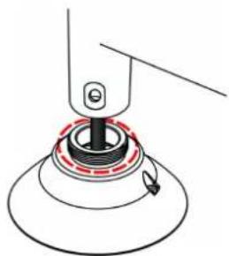
Sealing Cable Entry Hole
2.2 Mounting the Camera
Following are the methods of mounting the Quasar IR PTZ series cameras.
Ceiling Mount
Pole Mount
Corner Mount
Wall Mount
Mini-Pendant Mount

Note:
Each method includes several mounting types available as optional packages.
2.2.1 Ceiling Mount
Ceiling mount methods include:
■ Straight Tube Mounting (requires CD-HD-CAPX for indoor installation)
■ Swan Tube Mounting
2.2.1.1 Straight Tube Mounting Kit
The straight tube is available in two lengths: 25cm (10 inches) and 50cm (20 inches).
Items needed:
■ Outdoor mount kit (standard with outdoor cameras)
■ Straight tube mounting package (FLIR camera mounting option available separately)
- Screws and screw anchors for fixing the straight tube onto the ceiling (not provided)
Straight tube mounting package contents:
M8x12 screw x1
■ Spring washer 8x1
■ Pendant tube washer x1
■ Waterproof rubber gasket x1
Tools required:
Drill
■ Phillips and flat-headed screwdrivers
To install the straight tube mount
- Ensure that the ceiling can support the weight of the camera and straight tube.
- Cut a cable access hole in the ceiling.
- Attach the straight tube to the ceiling with the appropriate screws and screw anchors (not provided). For outdoor cameras, attach the waterproof gasket to the straight tube.
- Thread the cables through the straight tube and the outdoor mount kit.
- After threading the cables, block the entry hole with the supplied sponge to prevent insects from entering.
- Attach the outdoor mount kit to the straight tube with the supplied screws and washers.
- For outdoor cameras, adjust the waterproof gasket to the joint.
- Connect the cables to the camera.
- Secure the camera to the outdoor mount kit.
- Ensure the camera is fixed completely, and that the thread holes on the camera's fixing plate and the mount kit are aligned.
- Screw the supplied M5 standard screw/security screw as shown in the figure below.

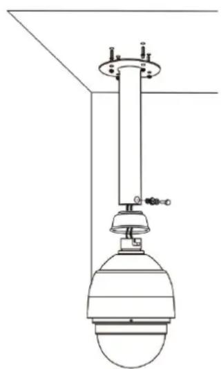
Figure : Ceiling Mounting: Straight Tube + Mount Kit
2.2.1.2 Swan Tube Mounting
Items needed:
- Outdoor mount kit (standard with outdoor cameras)
■ Swan tube mount package (FLIR camera mounting option available separately)
■ Screws and screw anchors for fixing the swan tube onto the floor (not provided)
Swan tube mounting package contents:
M8x12 screw x1
■ Spring washer 8 x1
- Pendant tube washer x1
■ Waterproof rubber gasket x1
Tools required:
Drill
■ Phillips and flat-head screw drivers
To install the swan tube mount
- Attach the swan tube to the mounting surface using the appropriate screws and screw anchors (not provided). For outdoor models, attach the waterproof gasket to the swan tube.
- Thread the cables through the swan tube and the outdoor mount kit.
- Attach the outdoor mount kit or outdoor PTZ camera mount to the swan tube using the supplied screws and washers.
- For outdoor cameras, fit the waterproof gasket to the joint.
- Connect the cables to the camera.
- Secure the camera to the outdoor mount kit.
-
Ensure the camera is fixed completely, and that the thread holes on the camera's fixing plate and the mount kit are aligned.
-
Screw in the supplied M5 standard screw/security screw as shown in the figures below.


Figure : Swan Tube Mounting
2.2.2 Pole Mount
There are two methods for pole-mounting a camera:
- Pole Thin/Wide Direct Mounting
- Pole Thin/Wide Box Mounting
2.2.2.1 Pole Thin/Wide Direct Mounting
The pole thin/wide direct mount must be used in conjunction with the standard or compact wall mount.
Items needed:
- Outdoor mount kit (standard with outdoor cameras)
- Standard/compact wall mount package (FLIR camera mounting option available separately)
- Pole thin/wide direct mount package (FLIR camera mounting option available separately)
Pole thin/wide direct mounting package contents:
- Stainless steel straps x4
- M8x16screw x4
■ Spring washer 8x4 - Washerx4
■ Sponge x2
Tools required:
■ Stainless steel strap cutter
- Phillips and flat-head screwdrivers
To install the standard/compact wall mount with pole thin/wide direct mount
- Fasten the pole thin/wide direct mount to a pole with the supplied stainless straps.
- Thread the cables through the pole thin/wide direct mount.
- Attach the standard/compact wall mount to the pole thin/wide direct mount using the supplied screws and washers.
- Thread the cables through the standard/compact wall mount with the cables coming out of the pendant mount's outlet. For outdoor cameras, attach the waterproof gasket to the pendant mount.
- After threading the cables, block the entry hole with the supplied sponge to prevent insects from entering. See Standard or Compact Wall Mount, Step 3.
- Thread the cables through the outdoor mount kit and attach the mount kit to the standard/compact wall mount using the supplied screws and washers.
-
For outdoor cameras, adjust the waterproof gasket to the joint.
-
Connect the cables to the camera.
-
Secure the camera to the outdoor mount kit.
-
Ensure the camera is fixed completely, and that the thread holes on the camera's fixing plate and the mount kit are aligned.
-
Screw in the supplied screw and washer.

Figure : Pole Direct Mounting: Pole Thin/Wide Direct Mounting + Standard Wall Mount + Mount Kit
2.2.2.2 Pole Thin/Wide Box Mounting
The pole thin/wide box mount must be used in conjunction with the standard or compact wall mount.
Items needed:
- Outdoor mount kit (standard with outdoor cameras)
- Standard/compact wall mount package (FLIR camera mounting option available separately)
- Pole thin/wide box mount package (FLIR camera mounting option available separately)
Pole thin/wide box mounting package contents:
■ Stainless steel straps x4
M8x16 screw x4
■ Spring washer 8 x4
- Washer8x4
- Sponge x2
Tools required:
■ Stainless steel strap cutter
■ Phillips and flat-head screw drivers
To install the standard/compact wall mount with pole thin/wide box mount
-
Fasten the pole thin/wide box mount to a pole with the supplied stainless straps.
-
Thread the cables through the pole thin/wide box mount.
-
Attach the standard/compact wall mount to the pole thin/wide box mount using the supplied screws and washers.
-
Thread the cables through the standard/compact wall mount with the cables coming out of the pendant mount's outlet. For outdoor cameras, attach the waterproof gasket to the pendant mount.
-
After threading the cables, block the entry hole with the supplied sponge to prevent insects from entering. See Standard or Compact Wall Mount, Step 3.
-
Thread the cables through the outdoor mount kit and attach the mount kit to the standard/compact wall mount using the supplied screws and washers.
-
For outdoor cameras, adjust the waterproof gasket to the joint.
-
Connect the cables to the camera.
-
Secure the camera to the outdoor mount kit.
-
Ensure the camera is fixed completely, and that the thread holes on the camera's fixing plate and the mount kit are aligned.
-
Screw in the supplied screw and washer.
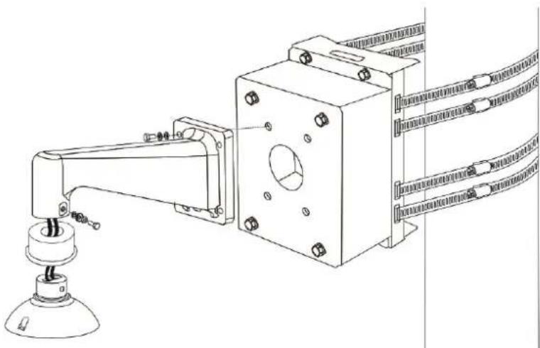
Figure : Pole Box Mounting: Pole Thin/Wide Box + Standard Wall Mount + Hard Ceiling Mount
2.2.3 Corner Mount
There are two methods to corner-mount the camera:
- Corner Standard Mounting Plate/Corner Plate Mini
■ Corner Thin/Wide Box Mounting
2.2.3.1 Corner Standard Mounting Plate/Corner Plate Mini
The corner/corner mini mounting plate must be used in conjunction with the standard or compact wall mount.
Items needed:
■ Outdoor mount kit (standard with outdoor cameras)
- Standard/compact wall mount package (FLIR camera mounting option available separately)
- Corner standard mounting plate/corner plate mini package (FLIR camera mounting option available separately)
■ Screws and screw anchors for fixing the corner mounting plate (not provided)
Corner standard mounting package contents:
- M8x16screw x4
■ Spring washer 8 x4 - Washer 8x4
■ M8 Nutx4 - Spongex2
Tools required:
Drill
- Phillips and flat-head screw drivers
To install the standard/compact wall mount with corner/corner mini mount
- Cut a cable access hole in the wall.
- Attach the corner mounting plate to the wall using the appropriate screws and screw anchors (not provided).
- Thread the cables through the corner mounting plate.
- Attach the standard/compact wall mount to the corner mount using the supplied screws and washers.
- Thread the cables through the standard/compact wall mount with the cables coming out of the pendant mount's outlet. For outdoor cameras, attach the waterproof gasket to the pendant mount.
-
After threading the cables, block the entry hole with the supplied sponge to prevent insects from entering. See Standard or Compact Wall Mount, Step 3.
-
Thread the cables through the outdoor mount kit and attach the mount kit to the standard/compact wall mount using the supplied screws and washers.
- For outdoor cameras, adjust the waterproof gasket to the joint.
- Connect the cables to the camera.
- Secure the camera to the outdoor mount kit.
- Ensure the camera is fixed completely, and that the thread holes on the camera's fixing plate and the mount kit are aligned.
- Screw in the supplied screw and washer.
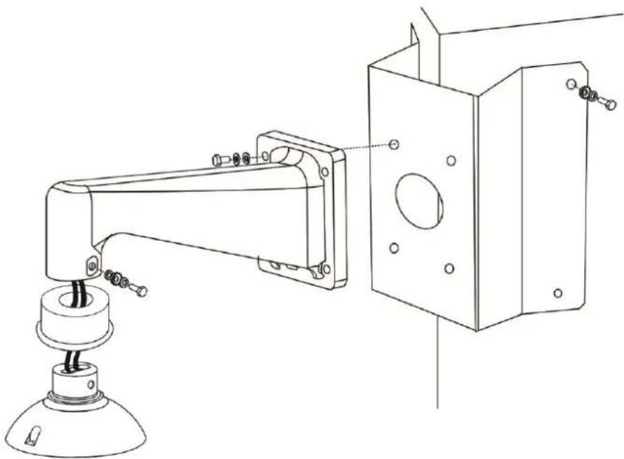
Figure : Corner Wall Mounting: Corner Standard/Mini Mounting Plate + Standard Wall Mount + Mount Kit
2.2.3.2 Corner Thin/Wide Box Mounting
The Corner thin/wide box mount must be used in conjunction with the standard or compact wall mount.
Items needed:
- Outdoor mount kit (standard with outdoor cameras)
- Standard/compact wall mount package (FLIR camera mounting option available separately)
- Corner thin/wide box mount package (FLIR camera mounting option available separately)
■ Waterproof rubber screws and screw anchors for fixing the Corner thin/wide box (not provided)
Wall box mounting package contents:
■ M8x16 screw x4
■ Spring washer 8 x4
- Washer 8x4
- Sponge x2
Tools required:
Drill
■ Phillips and flat-head screw drivers
To install the standard/compact wall mount with corner thin/wide box mount
- Cut a cable access hole in the wall.
- Attach the corner thin/wide box to the wall using the appropriate screws and screw anchors (not provided).
- Thread the cables through the corner thin/wide box.
- Attach the standard/compact wall mount to the corner thin/wide box using the supplied screws and washers.
- Thread the cables through the standard/compact wall mount with the cables coming out of the pendant mount's outlet. For outdoor cameras, attach the waterproof gasket to the pendant mount.
- After threading the cables, block the entry hole with the supplied sponge to prevent insects from entering. See Standard or Compact Wall Mount, Step 3.
- Thread the cables through the outdoor mount kit and attach the mount kit to the standard/compact wall mount using the supplied screws and washers.
- For outdoor cameras, adjust the waterproof gasket to the joint.
- Connect the cables to the camera.
- Secure the camera to the outdoor mount kit.
-
Ensure the camera is fixed completely, and that the thread holes on the camera's fixing plate and the mount kit are aligned.
-
Screw in the supplied screw and washer.

Figure : Corner Box Mounting: Corner Thin/Wide Box + Standard Wall Mount + Mount Kit
2.2.4 Wall Mount
Wall mount methods include:
• Standard or Compact Wall Mounting
• Wall Box Mounting
2.2.4.1 Standard or Compact Wall Mount_2
Items needed:
- Outdoor pendant mount (standard with outdoor cameras)
- Standard or compact wall mounting package (FLIR camera mounting option available separately)
- Screws and screw anchors for fixing the standard or compact wall mount (not provided)
Standard or compact wall mounting package contents:
M8x12 screw x1
Rubber washer 8 x1
■ Spring washer 8 x1
- Pendant tube washer x1
Spongex2
Tools required:
Drill
■ Phillips and flat-head screw drivers
To install the standard or compact wall mount
- Cut a cable access hole in the wall. Cables can also be threaded through the cable entry board on the mounting plate if desired.

- Attach the standard or compact wall mount to the wall using the appropriate screws and screw anchors (not provided). For outdoor models, attach the waterproof gasket to the wall mount.
- Thread the cables through the wall mount.
- After threading the cables, block the entry hole with the supplied sponge to prevent insects from entering. The sponge can be placed in one of two ways.


- Thread the cables through the outdoor mount kit and attach the pendant mount kit to the wall mount using the supplied screws and washers.
- For outdoor cameras, adjust the waterproof gasket to the joint.
- Connect the cables to the camera.
- Secure the camera to the outdoor mount kit.
-
Ensure the camera is fixed completely, and that the thread holes on the camera's fixing plate and the mount kit are aligned.
-
Screw in the supplied screw and washer.

Figure : Wall Mount: Compact Wall Mount + Mount Kit

Figure : Wall Mount: Standard Wall Mount + Mount Kit
2.2.4.2 Wall Box Mounting
The wall box mount must be used in conjunction with the standard or compact wall mount.
Items needed:
- Outdoor mount kit (standard with outdoor cameras)
- Standard/compact wall mount package (FLIR camera mounting option available separately)
■ Wall box mount package (FLIR camera mounting option available separately) - Screws and screw anchors for fixing the wall box mount (not provided)
Wall box mounting package contents:
M8x16 screw x4
Spring washer 8 x4
- Washer 8x4
- Sponge x2
Tools required:
Drill
- Phillips and flat-head screw drivers
To install the standard compact wall mount with wall box mount
- Cut a cable access hole in the wall.
- Attach the wall box mount to the wall using the appropriate screws and screw anchors (not provided).
- Thread the cables through the wall box mount.
- Attach the standard/compact wall mount to the wall box mount using the supplied screws and washers.
- Thread the cables through the standard/compact wall mount with the cables coming out of the pendant mount's outlet. For outdoor cameras, attach the waterproof gasket to the pendant mount.
- After threading the cables, block the entry hole with the supplied sponge to prevent insects from entering. See Standard or Compact Wall Mount, Step 3.
- Thread the cables through the outdoor mount kit and attach the mount kit to the standard/compact wall mount using the supplied screws and washers.
- For outdoor cameras, adjust the waterproof gasket to the joint.
- Connect the cables to the camera.
- Secure the camera to the outdoor mount kit.
-
Ensure the camera is fixed completely, and that the thread holes on the camera's fixing plate and the mount kit are aligned.
-
Screw in the supplied screw and washer.

Figure : Wall Box Mounting: Wall Box Mount + Standard Wall Mount + Mount Kit
2.2.5 Mini-Pendant Mount
A mini-pendant mount is available as an optional accessory for mounting the PTZ camera.
Items needed:
- Power cable
- Ethernet cable
• Mini-pendant mount kit - Mounting kit
- Screws and screw anchors for fixing the mini-pendant mount
Package contents:
- Mini-Pendant
• M3x8 screw with Spring Washer 8x1
• Camera lanyard chain x1 - Nylon Spacer
Tools required:
- Drill
• Phillips and flat-head screw drivers - PTFE thread seal tape
To install the standard or compact wall mount
- Insert the nylon spacer to M3x8 screw with spring washer-8.

- Fix the screw to the camera lanyard chain.

- Open the mounting plate.

- Screw the camera lanyard chain to the mini pendant mount and insert the chain through the pendant. DO NOT fasten the mounting plate back to pendant mount yet.

-
Make a cable entry hole on the wall to recess the cables.
-
Run the Ethernet cable through the pendant mount. If there are other cables, such as power cable, alarm I/O cable or audio I/O cable, also insert them through the pendant mount.
-
Align the screw holes on the pendant mount with the drilled holes and fix the pendant mount to the wall with four screws.
-
Wrap the PTFE thread seal tape (not supplied) five times around the threads of the pendant cap for waterproofing.

- Thread the Ethernet cable and other cables through the pendant cap and fix the pendant cap to the pendant mount.

- Hook the camera lanyard ring of the camera to the camera lanyard chain.

- Connect all cables and wires. See Camera Connectors in the CB-6302 User and Installation Guide.
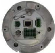
- Slightly pull the camera lanyard chain and other cables into the pendant tube. Then screw the mounting plate back to the mini pendant mount.


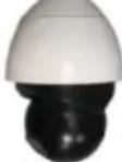
- Fix the camera to the mounting kit with the supplied screw and washers.



FLIR Systems, Inc.
6769 Hollister Ave.
Goleta, CA 93117
USA
PH: +1 805.964.9797
PH: +1 877.773.3547 (Sales)
PH: +1 888.747.3547 (Support)
FX: +1 805.685.2711
www.flir.com/security
Corporate Headquarters
FLIR Systems, Inc.
27700 SW Parkway Ave.
Wilsonville, OR 97070
USA
PH: +1 503.498.3547
FX: +1 503.498.3153
- PROPER DISPOSAL OF ELECTRICAL AND ELECTRONIC EQUIPMENT (EEE)
- DOCUMENT HISTORY
- TABLE OF CONTENTS
- 1 DOCUMENT SCOPE AND PURPOSE
- NOTE
- REMARQUE
- AVERTISSEMENT
- GENERAL CAUTIONS AND WARNINGS
- SAVE ALL SAFETY AND OPERATING INSTRUCTIONS FOR FUTURE USE
- CAUTION
- ATTENTION
- 2 INSTALLATION
- RELATED LINKS
- 2.1 WATERPROOFING THE CAMERA CABLES
- 2.2 MOUNTING THE CAMERA
- 2.2.1 CEILING MOUNT
- 2.2.1.1 STRAIGHT TUBE MOUNTING KIT
- ITEMS NEEDED
- STRAIGHT TUBE MOUNTING PACKAGE CONTENTS
- TOOLS REQUIRED
- TO INSTALL THE STRAIGHT TUBE MOUNT
- 2.2.1.2 SWAN TUBE MOUNTING
- SWAN TUBE MOUNTING PACKAGE CONTENTS
- TO INSTALL THE SWAN TUBE MOUNT
- 2.2.2 POLE MOUNT
- 2.2.2.1 POLE THIN/WIDE DIRECT MOUNTING
- POLE THIN/WIDE DIRECT MOUNTING PACKAGE CONTENTS
- TO INSTALL THE STANDARD/COMPACT WALL MOUNT WITH POLE THIN/WIDE DIRECT MOUNT
- 2.2.2.2 POLE THIN/WIDE BOX MOUNTING
- POLE THIN/WIDE BOX MOUNTING PACKAGE CONTENTS
- TO INSTALL THE STANDARD/COMPACT WALL MOUNT WITH POLE THIN/WIDE BOX MOUNT
- 2.2.3 CORNER MOUNT
- 2.2.3.1 CORNER STANDARD MOUNTING PLATE/CORNER PLATE MINI
- CORNER STANDARD MOUNTING PACKAGE CONTENTS
- TO INSTALL THE STANDARD/COMPACT WALL MOUNT WITH CORNER/CORNER MINI MOUNT
- 2.2.3.2 CORNER THIN/WIDE BOX MOUNTING
- WALL BOX MOUNTING PACKAGE CONTENTS
- TO INSTALL THE STANDARD/COMPACT WALL MOUNT WITH CORNER THIN/WIDE BOX MOUNT
- 2.2.4 WALL MOUNT
- 2.2.4.1 STANDARD OR COMPACT WALL MOUNT_2
- STANDARD OR COMPACT WALL MOUNTING PACKAGE CONTENTS
- TO INSTALL THE STANDARD OR COMPACT WALL MOUNT
- 2.2.4.2 WALL BOX MOUNTING
- TO INSTALL THE STANDARD COMPACT WALL MOUNT WITH WALL BOX MOUNT
- 2.2.5 MINI-PENDANT MOUNT
- PACKAGE CONTENTS
Brand : FLIR
Model : Quasar CP-6302
Category : Security Camera