
KWGE-K90 - Cooker Ravanson - Free user manual and instructions
Find the device manual for free KWGE-K90 Ravanson in PDF.


| Product Type | Electric Cooker |
| Model | KWGE-K90 |
| Brand | Ravanson |
| Dimensions (approx.) | 40 x 30 x 8 cm |
| Weight | 3.2 kg |
| Power Consumption | 2000 W |
| Voltage / Frequency | 220-240 V / 50-60 Hz |
| Number of Cooking Zones | 2 |
| Fuel / Energy Source | Electric |
| Main Material | Stainless Steel |
| Control Type | Rotary Knobs |
| Safety Features | Overheat Protection, Auto Shut-off |
| Cleaning and Maintenance | Wipe with damp cloth; avoid abrasive cleaners |
| Spare Parts Availability | Contact Ravanson support or authorized dealers |
| Repairability | Modular design; service centers available |
| General Information | Portable electric cooker for home use; includes user manual |
Frequently Asked Questions - KWGE-K90 Ravanson
User questions about KWGE-K90 Ravanson
0 question about this device. Answer the ones you know or ask your own.
Ask a new question about this device
Download the instructions for your Cooker in PDF format for free! Find your manual KWGE-K90 - Ravanson and take your electronic device back in hand. On this page are published all the documents necessary for the use of your device. KWGE-K90 by Ravanson.
USER MANUAL KWGE-K90 Ravanson
Original instruction
freestanding Gas-Electric oven
UA
natural_image
Line drawing of a Roanakon oven with control knobs and door, dimensioned 850-890 (no text or symbols on the device itself)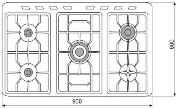
natural_image
Technical diagram of three identical fan-shaped structures with internal circular components, each labeled with a dimension (900 and 600) for scale, no text or symbols present.KOMPLETACJA
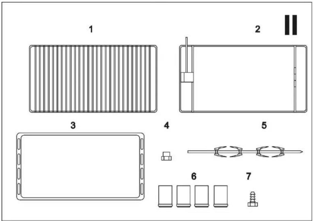
patrz Rys. II
flowchart
graph TD
    A["Step 1: Circle with square markers"] --> B["Step 2: Circle with square markers"]
    B --> C["Step 3: Circle with rectangle and arrow"]
    C --> D["Step 4: Circle with square markers"]
    D --> E["Step 5: Circle with square markers"]
    E --> F["Step 6: Circle with square markers"]
    F --> G["Step 7: Circle with square markers"]
natural_image
Simple circular diagram with concentric rings and small stars, no text or symbols present1
natural_image
Abstract circular diagram with concentric rings and small star symbols at top and bottom (no text or labels)2
natural_image
Abstract circular diagram with concentric rings and small star symbols at top (no text or labels)3
natural_image
Simple circular diagram with concentric rings and small stars, no text or symbols present4
natural_image
Close-up of a metallic mechanical component with threaded end and flange (no visible text or symbols)2.
natural_image
Close-up of a metallic mechanical component with threaded end and shaft (no visible text or symbols)3.
natural_image
Close-up of mechanical components with a white arrow pointing to a component (no visible text or symbols)natural_image
Diagram showing a circular structure with arrows and stars, no text or symbols presentXV
UWAGA!
Before use, read all safety instructions and warnings.

Failure to follow the safety warnings and instructions below and improper installation and use of the device may result in serious injury or death due to burns, fire, electric shock and carbon monoxide poisoning.
Please keep all warnings and safety tips for future reference.
GENERAL SAFETY INSTRUCTIONS
The device should be installed in accordance with applicable law and used only in well-ventilated rooms. PLEASE READ THE OPERATING MANUAL BEFORE INSTALLATION AND USE.
Connecting the equipment to the internal gas installation or to a cylinder with liquefied gas and its adjustment SHOULD ONLY BE PERFORMED BY AN AUTHORIZED installer of gas equipment or a technician from an authorized service facility, in accordance with applicable regulations, which should be confirmed by an entry in the product warranty card. Failure to provide such confirmation invalidates the warranty.
ATTENTION! The manufacturer is not liable for damage resulting from failure to comply with applicable standards and regulations or connection of the cooker by an unauthorized person.
The device and its accessible parts become hot during use.
Particular attention should be paid to the possibility of touching the heating elements. Children under 8 years of age should stay away unless under constant supervision.
-
This device must be installed in accordance with applicable regulations.
-
Installation and maintenance of the device must be carried out by a qualified person.
-
The manufacturer assumes no responsibility for any injury or damage caused by improper installation of the device or its incorrect use.
-
Any changes and modernizations on your own are prohibited, under pain of losing your warranty rights.
-
The device is intended for use by adults only. Do not allow children to play near the device.
-
This equipment is not intended for use by persons (including children) with reduced physical, sensory or mental capabilities, or persons who lack experience or knowledge of the equipment, unless this is done under supervision or in accordance with the instructions for use of the equipment provided by people responsible for their safety.
-
Please pay attention to children so that they do not play with this appliance.
-
The appliance is intended for preparing food in household conditions only. Use it for other purposes is not permitted!
-
The appliance should only be repaired by an authorized service center using original spare parts.
-
Improperly performed repairs may pose a significant threat.
-
In the event of a device failure, especially in the event of gas leakage, the device must be disconnected from the gas supply and contact the service center immediately.
-
In case of gas leakage, immediately close the valve on the gas installation or on the cylinder with gas, ventilate the room thoroughly and call an emergency gas service. During this time, you must not light matches, smoke cigarettes, turn on or turn off electrical appliances (radio, bell, light switch) or mechanical, causing sparks.
ATTENTION!
Liquid gas is heavier than air and therefore has tendencies to accumulate on the lower levels. Rooms, in which liquid gas cylinders
are installed should be equipped with ventilation ducts, led out from the room to the outside, enabling escape gas in the event of a leak. For the same reason, gas cylinders, both empty and partially filled, should neither be installed nor stored in rooms located underground (e.g. in basements). The cylinders cannot be located too close to heat sources (stoves, fireplaces, ovens, etc.) that could increase the temperature inside the cylinder above 50°C.
- Do not be lift this appliance by the oven handle!
- Before use, remove all protective protection applied during transport.
- The materials from which the packaging is made are suitable for use as secondary raw materials.
- A worn out appliance must be restored to a condition that makes it impossible to re-use it. Oven doors should be removed as they may be a source of danger, especially for children. Then hand over the device to specialized units dealing with disposal or purchasing secondary raw materials.
- Before installation, check the pressure at the installation place and the type of gas used in the appliance is adapted.
- The conditions for changing the type of gas used can be found in the user manual and on the rating plate on the device.
- THE RATING PLATE IS LOCATED IN A VISIBLE POSITION ON THE BACK OF DEVICE.
- DO NOT REMOVE THE RATING PLATE FOR ANY REASON.
- Make sure the power source to which the device to be connected corresponds to the parameters given on the rating plate.
- The power cord can't touch with sharp edges and hot surfaces.
- The plug of the device must fit into the socket.
- Do not modify the plug in any way.
- Do not leave the device during the work without any supervision.
- The flame of the burners should be regular and stable.
If the flame is not regular, clean the burner.
In case of a fault, call an authorized service center.
-
Check that the knobs are in the "0" (off) position when the cooker is not in use.
-
Do not leave aluminum foil or other objects on the top of device (on the burners) if the burners are on.
- Heat and moisture are generated when the oven is in operation. In the room, where the device will be located the proper ventilation must be ensured
- Room, where the device will be located should have efficient supply and exhaust ventilation. Improper ventilation may lead to disruption of the gas combustion process and the formation of an increased carbon monoxide content in the room.
- If the appliance is operated for a long time, additional ventilation should be provided by opening a window or increasing the power of mechanical ventilation (if installed).
- When cooking food using oil or other fat, do not leave the appliance unattended, overheated oil may catch fire.
- Do not place deformed or unstable pots on the grate, it may tip over and the contents of the pot will spill onto the burners.
- If other electrical appliances are connected near the appliance, make sure that their power cables do not touch the hot elements (or not jammed by the oven door).
- The appliance becomes hot during use. Be especially careful when inserting and removing food from the oven. The heating elements inside the oven are very hot.
- Do not place heavy pots on the open oven door, do not sit or stand on it.
- When the oven is in operation, its glass and external elements become very hot.
Please pay special attention to children when using this feature of the device. - The grill grate becomes hot while the oven is in operation.
Use protective gloves to remove food and the grate. - Do not cover the bottom of the oven chamber with foil, as heat may accumulate and damage the oven.
-
Do not open the oven door while it is in operation without need or when it is still warm, to protect the knobs from damage. After baking, remove the food from the oven and close the oven door.
-
Only use the accessories provided by the manufacturer.
- In addition to the oven accessories, use heat-resistant cookware intended for use in ovens (see the cookware manufacturer's instructions).
- Cleaning agents and flammable materials should not be stored near the appliance.
- The connection hose should be replaced after the specified time, in accordance with the manufacturer's instructions.
- Periodically check the condition of the hose and the tightness of the connection, in accordance with applicable regulations.
- For safety and hygiene reasons appliance should be kept clean.
- This appliance should be washed after each use.
- Use a soft, damp cloth to clean the device (not wet) cloth and mild detergent.
- Do not use pressure or steam cleaning devices to clean this appliance.
- Do not use solvents, gasoline or other agents that may damage the device.
- Pay special attention for the air vent, it must be clean, unobstructed and free from any obstacles.
- Do not expose the device to rain and humid conditions.
- Transport of the device in original packaging to protect against mechanical damage and dust.
- Despite using the device as intended and following all safety instructions, certain residual risk factors cannot be completely eliminated.
USER TIPS
BEFORE FIRST USE
After receiving your device, please:
- Unpack it and check it for damage. If any damage is detected - DO NOT USE
- Check the completeness of the supplied equipment
- Remove all packaging elements
- Remove all accessories from the oven cavity
- Remove protective elements
- Wash all accessories before use
Before connecting to the power source, check whether the power source to which the device is to be connected meets the parameters given on the rating plate.
Before using the device for the first time, warm up the empty oven to get rid of the smell of thermal insulation and any remaining maintenance greases.
Turn on the oven for min. 45 minutes by turning the temperature setting knob (see: CONTROL PANEL - OPERATION) to the maximum position. Smoke may come out of the oven. This is normal. Preheat the oven until the smoking and unpleasant smell stop. Ventilate the room where the appliance is installed thoroughly.
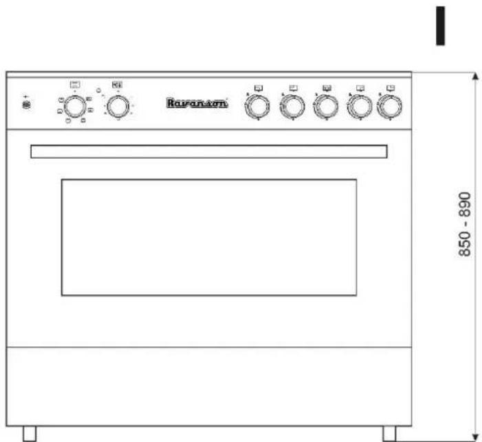
GENERAL VIEW OF THE FRONT AND THE MAIN BOARD
see Figure I
natural_image
Technical diagram of three identical fan-shaped structures with internal circular components, each labeled with a dimension (900 and 600) for scale, no text or symbols present.COMPLETION
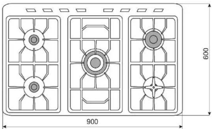
see Figure. II
| 1 | Grid | 2 | Grid for rotisserie |
| 3 | Metal tray | 4 | Dummy plug |
| 5 | Rotisserie rod and forks | 6 | Feets– 4pcs |
| 7 | Hose adapter |
VIEW OF THE MAIN BOARD
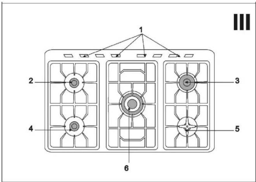
see Fig. III
1 - ventilation holes
4 - medium burner
2 - medium burner
5 – small burner
3 - big burner
6 - "crown" burner
flowchart
graph TD
    A["Step 1: Circle with vertical arrows"] --> B["Step 2: Circle with horizontal arrows"]
    B --> C["Step 3: Circle with vertical arrows"]
    C --> D["Step 4: Circle with horizontal arrows"]
    D --> E["Step 5: Circle with vertical arrows"]
    E --> F["Step 6: Circle with horizontal arrows"]
    F --> G["Step 7: Circle with vertical arrows"]
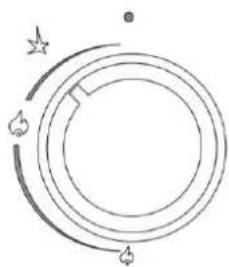
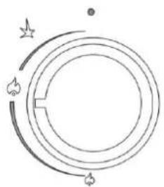
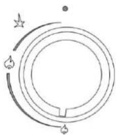
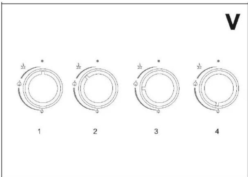
Burners control - see Fig. V
Before lighting the hob burners, check that the flame-spreader crowns are correctly in place with their respective burner caps, making sure that the holes in the flame-spreaders are aligned with the igniters and thermocouples.
Position 1 – Gas supply to the burner closed
Position 2 - Starting
To start the burner, turn the knob to position 2 and press it.
When pressed, the piezo igniter will activate. If the burner does not light within the first 15 seconds, turn the knob to 1 and wait at least 60 seconds before trying to light it again. After the burner lights up, keep pressing the knob, turn it to position 3 and wait about 10 seconds (keep pressing the knob until the flame goes out after releasing the knob).
Position 3 - Maximum flame
Position 4 - Minimum flame - saving
Oven operation - see Fig. VI
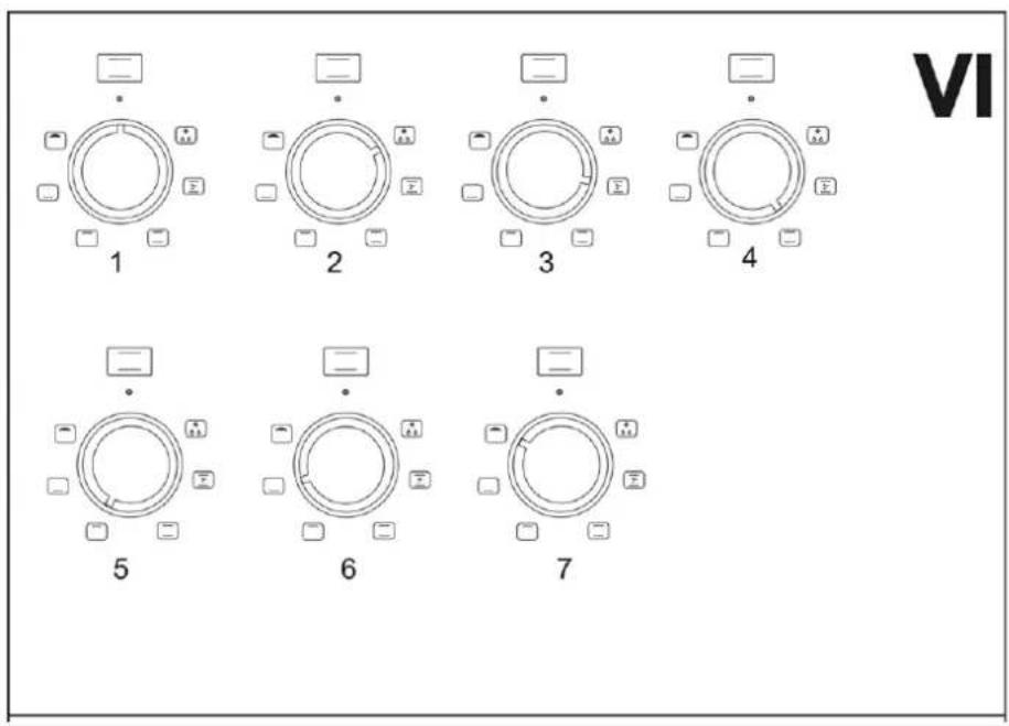
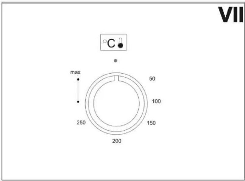
The oven is operated using knobs 3 and 4. Use knob 4 to select the desired oven function (Fig. VI). Use knob 3 to set the desired temperature (Fig. VII).
Position 1 - Oven off
Position 2 - Defrosting
This function is used to defrost food. When the defrosting function is turned on, the convection fans operate. Temperature setting knob 3 should be set to a temperature of approximately 50°C.
Position 3 – Convection Air
When working with this function, the convection fans and the lower and upper heaters are turned on. When baking with the convection function, the set temperature should be lower than when baking traditionally, using only the upper and lower heaters.
Position 4 - Upper and bottom oven heaters on - traditional baking
When working with this function, the food is heated from above and below. It is recommended to place the dish in the center of the oven.
Position 5 – Upper heater on
This function is used to bake food more strongly from the top.
Position 6 – Bottom heater on
This function is used to bake food more strongly from the bottom.
Position 7 - Rotisserie toasting function on
The grill element heats the food rotating on the spit from above.
ATTENTION!
The baking temperature and the selected oven function should be selected in accordance with the recipe for preparing the dish. In practice, there may be differences which should be corrected by the user based on your own experiences.
After the baking process is completed turn off the oven, turn knobs 3 and 4 to the 0 position.
Setting the oven temperature - see Fig. VII
This knob is used to select the desired baking temperature.
After selecting the oven function with knob 2, set the desired temperature. Turning on the oven heaters is signaled by control light 1. Once the set temperature is reached, the thermostat will turn off the heaters - control light 1 will go out. After the temperature in the oven drops, the thermostat will turn on the heaters again to reach the set temperature, and the lamp will also light up.
Using the rotisserie
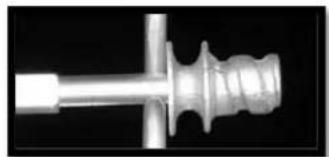
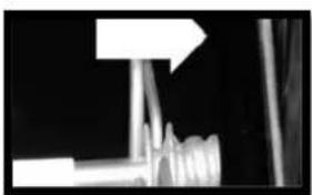
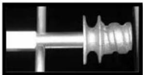
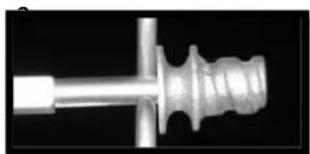
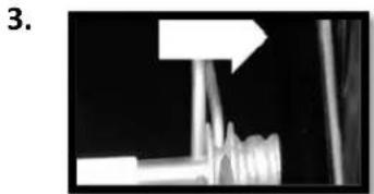
1) Place the food on the spit rod and secure it on both sides with forks 2) When placing the rotisserie, the oven must be turned off and cooled down 3) Thread the support frame onto the second runner from the bottom so that the rod's housing protrudes from the oven. Position frame into the oven until the end of the rod lines up with the rotisserie motor's hole. At this point, raise the rotisserie rod and push it to the left until it is in the position illustrated in figure (2).
4) Once baking is complete, use the included tool to slide the rod out of the hole (3) and remove the frame so that the rod can be removed from the oven.
5) Place the baking tray lower enough to protect the oven from getting dirty with dripping fat.
6) Set the OVEN FUNCTION KNOB (4) to Position 7, set the baking temperature WITH THE TEMPERATURE SETTING KNOB (3).
1.
natural_image
Close-up of a metallic mechanical component with threaded end and cylindrical shaft (no visible text or symbols)2.
natural_image
Close-up of a metallic mechanical component with threaded end and shaft (no visible text or symbols)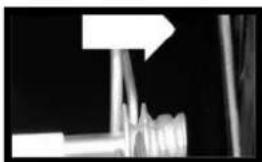
natural_image
Close-up of mechanical components with a white arrow pointing to a blank rectangular object (no text or symbols visible)After the baking process is completed, to turn off the oven, turn knobs 3 and 4 to the 0 position.
OVEN TIMER USER'S MANUAL
General overview
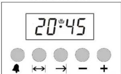
Electronic timer enables you to get the food ready to serve at the desired time. The only thing to be done is to program the cooking time and ready time. It can also be used as an alarm clock, where you just give in the amount of time after which it should remind you by a buzzer tone.
Power up
On power up, clock (0:00) and 'A' is flashing on the screen. The timer cannot be programmed and the clock has to be adjusted. In order to program the timer, you have to enter first the manual mode.
Manual mode
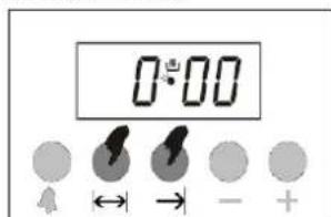
Press and release |←→| and buttons simultaneously.
Time of day adjustment
This adjustment can only made when no cooking program is in progress. First enter manual mode by pressing buttons 2 and 3 as shown in the picture above, then within 5 seconds, start to adjust the clock using + or - buttons. Long presses of those buttons will result in fast changes..
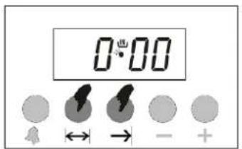
1) Enter manual mode adjust the time of day
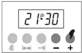
2) Using + or - buttons
Adjusting the buzzer alarm
With this feature, you can program after how much elapsed time you should be warned by a buzzer sound.
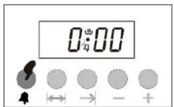
1) Switch to buzzer alarm
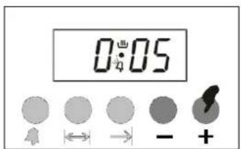
2) Give in the period of time
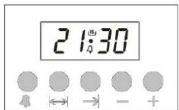
3)
After a few seconds, the
to be counted down the current time of day
screen will return to displaying
Cancelling the buzzer sound
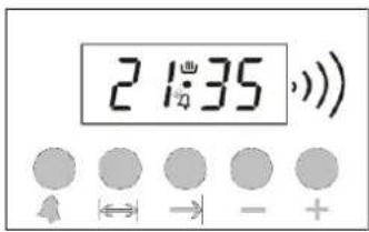
1) Buzzer will sound after the programmed amount of time.
2) Press the button to cancel the sound.
Automatic cooking program
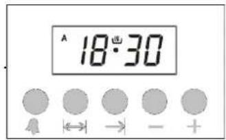
If you want to start cooking immediately, you just have to give in the cooking time.
Example: We placed our food into the oven and want it to be cooked for 2 hours 15 minutes.
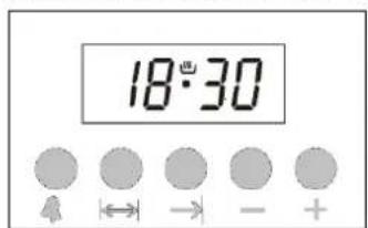
1) Current time is 18:30
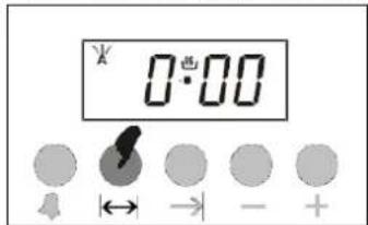
2 )Switch to cooking time adjustment mode
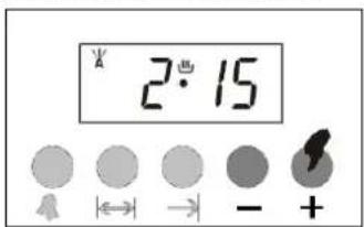
3) Adjust the cooking time using the + and - buttons.
Now, you have programmed your oven to cook the food for 2 hours and 15 minutes. Please do not forget the function and/or the temperature knobs of your oven to appropriate positions.
4) After a few seconds, the screen will indicate that cooking has started and show the current time of day.
Note: You may cancel the automatic cooking mode any time by entering manual mode
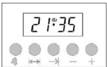
In the example above, cooking immediately started after giving in the cooking period. By pressing the button, you can see the ready time, i.e. the time when the food will be ready to serve, and if you want, you can also change it. In the example below, the ready time will be shifted to 21:30.
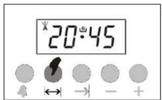
1) Displayed is the ready time 18:30 + 2:15 = 20:45 by using
2) Set it to the desired time g + or - buttons swit
3) In a few seconds, screen hes to clock mode.
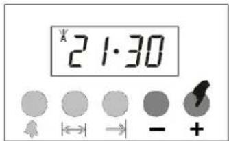
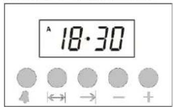
We now have programmed our oven to get the food ready at 21:30. Since the cooking time was preprogrammed as 2 hours and 15 minutes, your oven will start cooking at 19:15, so that the food is ready at 21:30.
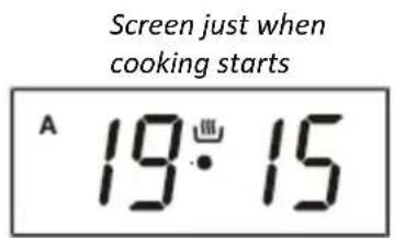
cooking ends
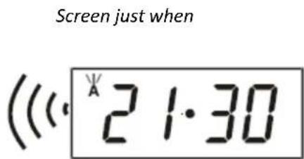
When automatic cooking is completed, a buzzer alarm is heard and will sound, if not stopped, for 7 minutes.
natural_image
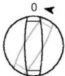
Simple line drawing of a sphere with internal geometric lines and a small arrow at the top (no text or symbols)1) Switch OFF 2) Reset the oven
inoperative until you
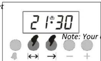
the timer
oven will be reset
In the example shown, cooking time has been programmed first; the ready time
was calculated automatically and was edited by us. It is also possible first to program the ready time. In that case, the cooking time will be calculated automatically and should be edited thereafter.
In case of mains power loss
The clock will appear as a flashing 0:00 together with the 'A' symbol. Any cooking program in progress will also be cancelled. Enter the manual mode and adjust the clock using + or - buttons.
Note: If you will not use your oven right now, be sure that that it is in OFF position.
Adjusting the buzzer tone:
You may adjust the buzzer tone of the timer in the following way:
1) Pressing and holding the ‘-’ button, you can hear the current buzzer tone. Releasing and pressing again will switch to the next tone (3 different tones available)
2) The buzzer tone will be set to the last adjusted tone.
Note: As factory setting, the buzzer volume is set to the high tone. In case of a long power loss, the set buzzer tone will be this one.
APPLIANCE SETTING
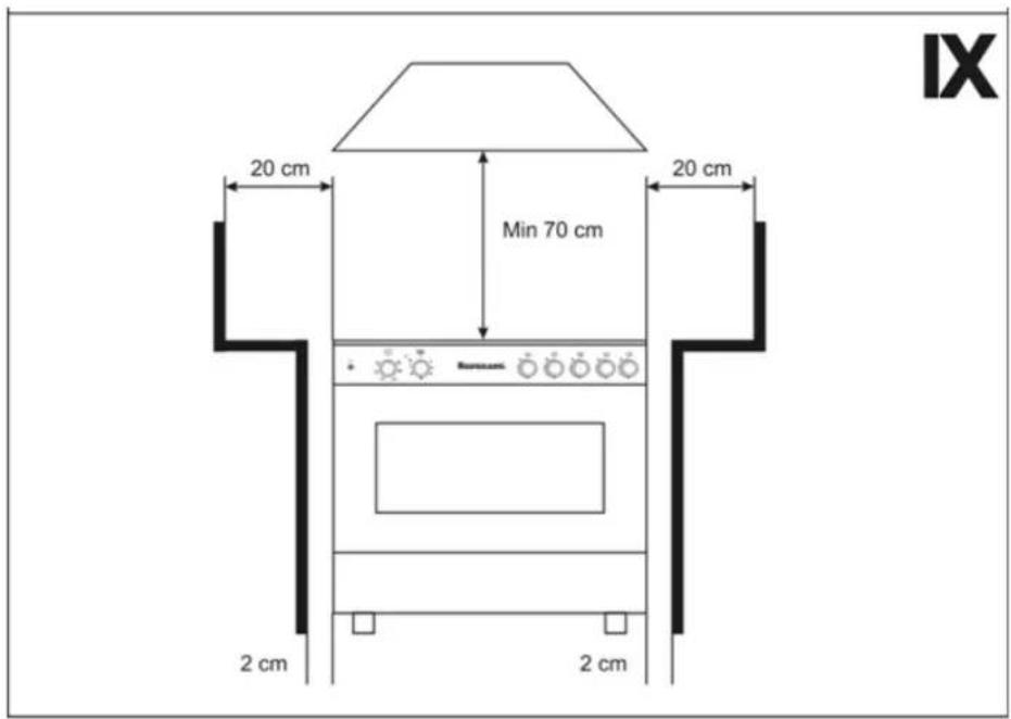
see Fig. IX
Before setting up the appliance, screw the legs into the sockets located at the bottom.
This device should be placed on a stable surface and leveled using legs. To obtain good cooking results, the appliance must be properly leveled. The height of the legs can be adjusted from 90 to 120 mm.
Minimum distances from the side and rear walls should be maintained. Do not place any flammable items (furniture, wooden shelves, etc.) above the kitchen. It is recommended to maintain the minimum distances shown in Fig. IX
Before installing a device in room, make sure that it meets the requirements of applicable regulations.
The room area should:
- Have a minimum height of 2.2 m
- Allow air to flow in, which is necessary for proper combustion of the gas. The air supply should be not less than 2m3/h per 1kW of burner power. Air can be supplied as a result of direct flow from the outside through a channel with a cross-section of min. 100 cm2 or indirectly from adjacent rooms that are equipped with exiting ventilation ducts outside
- Provide supply and exhaust ventilation (at least 1.5 air changes per hour)
- Ensure exhaust gases are discharged, e.g. through an efficient chimney duct
The room should be dry and airy and have efficient ventilation, in accordance with applicable technical regulations. The legal basis on which we assess the suitability of a room for installing a gas cooker is the Regulation of the Minister of Infrastructure of April 12, 2002 on the technical conditions that buildings should meet and their location (Journal of Laws 2002, No. 75, item 690).
COOKING
Selection of burners
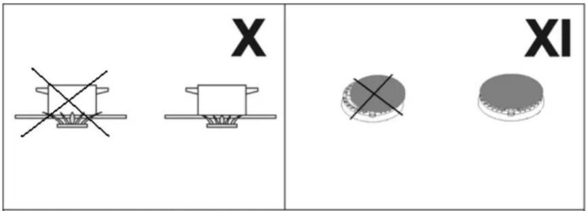
Above each knob there is a symbol for the corresponding burner. Always use a torch about the size of the appropriate diameter of the pot used for cooking. Do not allow the flame to extend beyond the diameter of the pot (see Fig. X).
For economic reasons, we recommend covering pots while cooking.
Do not allow cooking food to boil over onto the burner.
Keep the burner ring and holes clean.
Use cookware of the appropriate diameter on each burner.
Do not place deformed or unstable dishes on the grates, as they may tip over and flood the burners. Do not remove the grates and place dishes directly on the burners.
Do not place empty pots over the switched on burner.
Before removing the cookware from the burners, reduce the flame or turn it off completely.
Keep the burners properly clean, as impurities negatively affect their functioning.
Before turning on the burner, make sure that the knob you intend to turn on corresponds to the burner you want to ignite. The assignment of the knobs to the burners is shown symbol above the knob of each burner.
Pay attention to the correct positioning of the covers on the burners (see Fig. XI).
The device is equipped with gas outflow protection.
If the flame is accidentally extinguished due to flooding or gusts, the gas supply is automatically cut off. It may take 60-90 seconds from the uncontrolled flame extinguishment to the gas being cut off.
CLEANING AND MAINTENANCE
Before cleaning, check that all knobs are set to "off".
Please wait until the device cools down.
For cleaning, use a damp (not wet) cloth with a mild detergent.
Do not use scouring agents, corrosive agents or sharp objects for cleaning and materials.
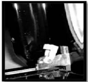
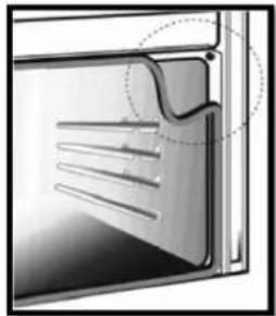
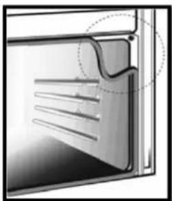
To permit thorough cleaning of the oven, the seal may be removed. Before removing the seal, take off the oven door as described above. Once the door has been taken off, lift the tabs at the corners as shown in the figure.
Lift the levers until they touch the hinges and take hold of the two sides of the doors with both hands close to the hinges. Raise the door to an angle of about 45^ and remove it. To reassemble, fit the hinges into their grooves, then lower the door into place and release the levers.
natural_image
Close-up of mechanical components with no visible text or symbols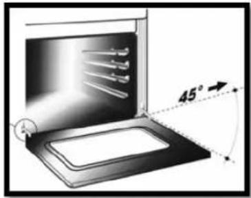
natural_image
Diagram of a door with ventilation duct and handle, showing no text or symbolsCHANGE OF A LIGHT BULB
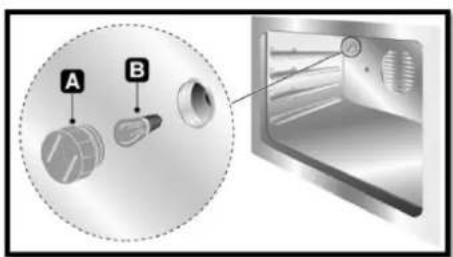
ATTENTION! Before replacing the bulb, disconnect the device from the power source! To replace the bulb, unscrew the cover (A), replace the bulb (B), put the cover back on.
Bulb parameters:
Rated voltage: 220 - 240 V
Rated power consumption: 25W
Rated frequency: 50 Hz
Cap: E 27
TRANSPORT AND STORAGE
Transport and store the device in its original protective packaging it against mechanical damage, moisture and dust.
ATTENTION! Do not move the kitchen by holding the oven handle
INSTRUCTIONS FOR THE INSTALLER
Connecting and adapting the device to the appropriate type of gas can be performed by a gas equipment installer with appropriate qualifications only, in accordance with applicable regulations.
After carrying out the above-mentioned activities, the installer should indicate in the TECHNICAL DATA table in the warranty card the type of gas for which the appliance has been adapted.
The manufacturer is not liable for damage resulting from failure to comply with applicable standards and regulations or connecting the device by an unauthorized person!
Remove the packaging and place the appliance in a dry, well-ventilated room. away from curtains. Do not store paper, alcohol, gasoline, etc. near the appliance.
The connection must be made in accordance with applicable standards and regulations!
The appliance is adapted to be powered by gas with the parameters specified on the rating plate.
Check whether the given gas characteristics correspond to the parameters of the feed gas.
The appliance is equipped with a pipe connector with a G½" thread. Connect the gas to the spigot using appropriate accessories.
The appliance can be connected to the internal home installation or to a liquefied gas cylinder.
Before starting the connection, the gas tap must be closed.
CONNECTION BY FLEXIBLE HOSE
ATTENTION!
Connection using a flexible hose can only be made after checking whether it's compatible with applicable regulations.
ATTENTION!
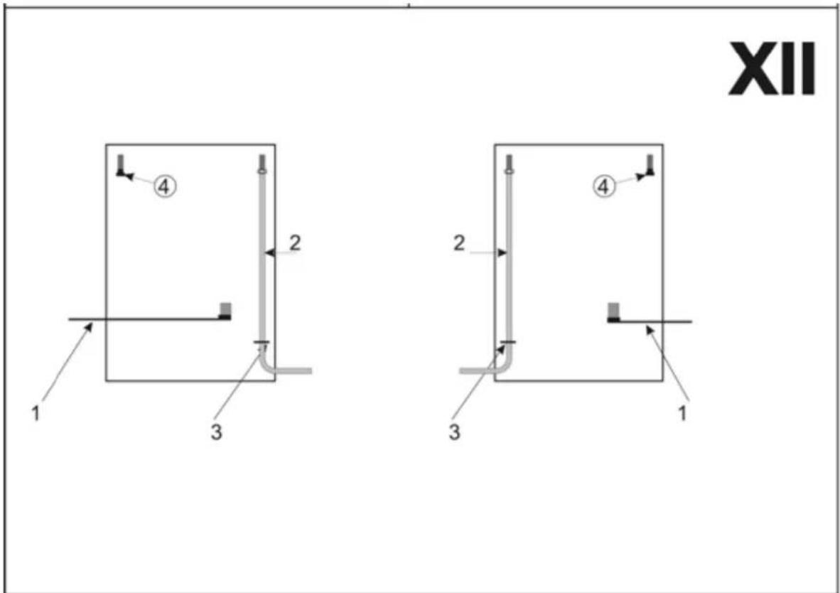
The appliance can be connected to gas on the right or left side. Screw the cap (4) onto the unused supply pipe - see COMPLETION, FIG. II. After connecting the appliance to the gas installation, check whether gas is leaking from under the cap.
1. Natural gas connection
The appliance can be connected to the gas installation "rigidly" or using a certified flexible metal hose.
The maximum length of the flexible hose should not exceed 2.0 m.
The hose should not come into contact with any moving parts and should not pass through a space where there is not enough space.
When connecting to a rigid piping system, take care to not cause stress at any point in the installation or in any part of the device.
At the end of installation, perform a gas leak test using a soapy solution.
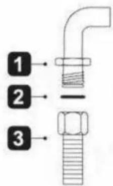
- Nipple G1/2
- Silicone gasket
- G1/2 gas hose (compliant with EN 14800
2. Connection to liquid gas
A certified rubber hose should be used to connect the device to the cylinder.
To connect the gas cylinder, use a reducer with a nominal gas pressure of 37 mbar
Connect the rubber conduit to the appliance spigot using a 0.5 m section of steel installation pipe (seamless).
The length of the hose must not exceed 1.5 meters without any kinks or twists.
The hose must not run close to sharp edges or objects with sharp ends.
The hose should not be routed near sources of high temperature.
The cable must be accessible to allow inspection for abrasion or wear along its entire length.
If the hose is not perfectly tight and gas is leaking, do not try to repair it: replace it with a new one.
Check the hose for expiry date (marked with a series on the hose itself).
ATTENTION! Installation and replacement of gas cylinders should be carried out away from sources of ignition.
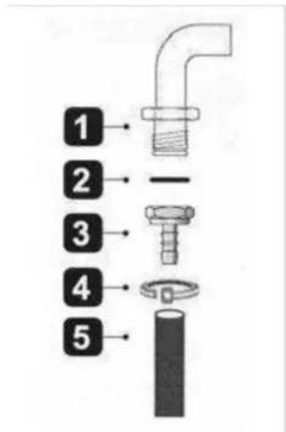
- Nipple G1/2
- Silicone gasket
- G1/2 connector
- Clamp
- Rubber hose (inner diameter 8 mm)
The correct routing of the gas supply hose is shown in Fig. XII
- Power cord
- Gas supply hose
- Clamp
ATTENTION!
Each time you connect the appliance to gas cylinder, check the tightness of the cylinder valve and the connection of the reducer with cylinder and its operation.
ATTENTION!
- It is unacceptable to check tightness using an open flame (e.g. a match or light up). There is a risk of explosion! You can use soapy water to check for leaks
- Periodically check the condition of the hose and the tightness of the connection, in accordance with applicable regulations
- The rubber hose should not touch hot appliance elements.
ATTENTION! CONNECTION BY RUBBER HOSES COMPLIANT WITH CURRENT REGULATIONS IS ONLY ALLOWED IF THE ENTIRE LENGTH OF THE HOSE IS POSSIBLE TO CONTROL
The device is made in the second category and can operate on two types of gas II2E3B/P. By default, the device is set to gas from family 2.
2E - high-methane natural gas GZ20 - 20mbar (factory setting).
The device can be powered by gas from family 3: 3B/P – propane butane.
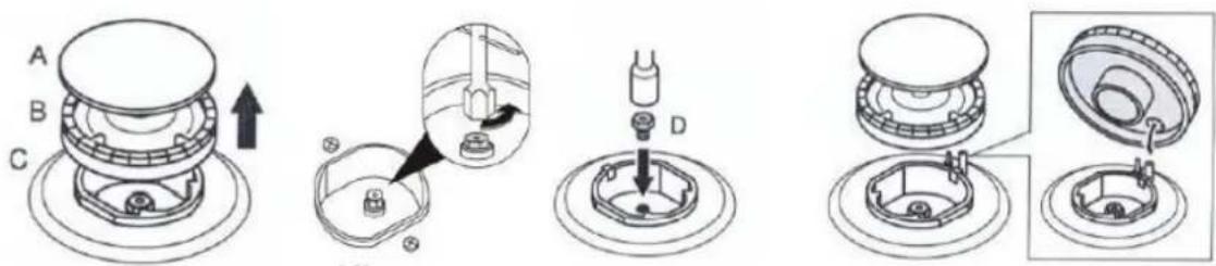
In order to adapt the device to propane-butane (PB/P) gas, the nozzles must be replaced.
REPLACING NOZZLES
To replace the nozzles:
-
Wait until the appliance cools down
-
Remove the grate
-
Remove the burner caps
-
Unscrew the nozzles using a socket wrench "7" and replace them with nozzles adapted to the feed gas
-
Install the burner caps and grate
FLAME ADJUSTMENT
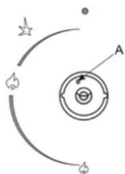
- see Fig. XV
The valves are adjusted by adjusting the economy flame. To do this, you should:
- turn the knob to turn on the adjustable valve
- set the knob to position 4 (Fig. V)
• in position 4, remove the knob from the valve - turn the adjustment screw (A) and observe the flame
The flame should be set at such a height that it does not go out in the event of a slight breeze and when quickly switched from full flame - position 3 (Fig. V) and vice versa. A properly adjusted flame should have the shape of a green-blue cone, approximately 2-4 mm high.
Place the knob on the valve.
natural_image
Diagram showing a circular structure with arrows and star symbols, no readable text or labelsXV
ATTENTION!
If there are visible changes in gas pressure in the gas installation, the safety flame should be adjusted at low pressure so that the burner does not go out during normal use.
POWER TABLE AND NOZZLE DIAMETERS DEPENDING ON THE TYPE OF SUPPLY GAS
| Gas type | Burner | |||
| 2E - G20 – 20 mbar | Small | Middle | Big | WOK |
| Diameter injector [mm] | 0,70 | 0,95 | 1,20 | 1,30 |
| Nominal input [kW] | 0,90 | 1,65 | 2,80 | 3,20 |
| Gas consumption [m3/h] | 0,086 | 0,158 | 0,267 | 0,305 |
| Gas type | Burner | |||
| 3B/P-G30 37mbar | Small | Middle | Big | WOK |
| Diameter injector [mm] | 0,50 | 0,65 | 0,80 | 0,9 |
| Nominal input [kW] | 0,95 | 1,75 | 2,80 | 3,30 |
| Gas consumption [g/h] | 66 | 120 | 204 | 225 |
ELECTRICAL CONNECTION
Make sure that the voltage and cross-section of the power cord match the specifications indicated on the rating plate located on the back of the appliance.
Do not remove this sign under any circumstances.
The connection to the power grid can be permanent or via a plug and socket. In the latter case, the plug and socket must be suitable for the cable used and comply with applicable regulations. Regardless of the type of connection, the device must be grounded. Before connecting, make sure the power line is properly grounded.
COMMON FAULTS
-
Ignition does not ignite the gas or does not always ignite it
-
Check if the appliance is connected to the electricity network
- Clean and dry the burner components and ignition
-
Check that the burner caps and caps are installed correctly
-
The gas does not ignite
-
Check whether the rubber hose has not been crushed when powered by liquid gas from the cylinder
- Check that the main gas valve is open
- Check whether the gas cylinder is not empty
- If a new appliance has been installed or the gas cylinder has been replaced with a new one, the ignition procedure must be repeated until the gas reaches the burner
-
Check whether the nozzle or flame holes in the burner are not dirty or flooded. If so, clean the nozzle hole using a pin or needle. Use a brush to clean the holes in the burner. Then dry all the elements
-
Unstable flame
- Check whether the burner components are clean, dry and correctly installed if the above suggestions do not solve the problem, contact the service.
It is forbidden not to attempt to repair it yourself. The device may only be repaired by a qualified, authorized person.
The appliance should only be repaired by an authorized service center using original spare parts.
The current list of service points can be found at: www.ravanson.pl Service is provided by the Quadra-Net network, please visit: www.quadra-net.pl Service number: 61 853 44 44
TECHNICAL PARAMETERS
Rated voltage: 220 - 240V IP 20
Rated frequency: 50/60 Hz
Gas: G20 - 20 mbar
Maximum power consumption: 2955 W
Category: II2E3B/P
The device is made in Protection Class I
PIN 1312CL5460
Country of destination – PL (Poland)
Rated power consumption of individual elements:
Lower heater 1700 W
Upper heater 1200 W
Grill 1800 W
Lamp 2 X 15 W
Rotisserie motor 2 x 6W
Fan 25 W
The symbol presented below indicates that the used equipment cannot be placed together with other household waste. The user is obliged to bring this item to the waste electrical and electronic equipment collection point where a suitable system is created to allow safe disposal of these items.
Dangerous components present in electrical and electronic equipment have negative
consequences for the environment and human health therefore correct handling of the equipment is very important. Certain substances which may adversely affect the environment over the life of the product and after use have been limited in this device
Information for domestic ovens
| Symbol | Value | Unit | |
| Model identification | KWGE-K90 GLASS INOX KWGE-K90 GLASS BLACK | ||
| Type of oven | Electric | ||
| Mass of the appliance | M | kg | |
| Number of cavities | 1 | ||
| Heat source per cavity (electricity or gas) | Electricity | ||
| Volume per cavity | V | 105 | |
| Energy consumption (electricity) required to heat a standardised load in a cavity of an electric heated oven during a cycle in conventional mode per cavity (electric final energy) | EC_electric cavity | 0,951 | kWh/cycle |
| Energy consumption required to heat a standardised load in a cavity of an electric heated oven during a cycle in fan-forced mode per cavity (electric final energy) | EC_electric cavity | 0,999 | kWh/cycle |
| Energy consumption required to heat a standardised load in a gas-fired cavity of an oven during a cycle in conventional mode per cavity (gas final energy) | EC_gas cavity | N/A | MJ/cyclekWh/cycle(1) |
| Energy consumption required to heat a standardised load in a gas-fired cavity of an oven during a cycle in fan-forced mode per cavity (gas final energy) | EC_gas cavity | N/A | MJ/cyclekWh/cycle |
| Energy Efficiency Index per cavity | EEI_cavity | 95,9 | |
| Energy Efficiency Index per cavity in fan-forced convection mode | EEIcavity | 101,0 | |
| (1)1 kWh/cykl = 3,6 MJ/cykl | |||
Measurement methods according to: EN 60350-1:2016
Energy saving tips
- The oven door must be closed during cooking. The door can be opened to turn the food over. In order to maintain the right temperature and save energy, the oven door should not be opened frequently during cooking.
- If cooking takes longer than 30 minutes, the oven can be switched off about 5-10 minutes before the end of the cooking time to save energy.
- Plan the cooking process for several dishes to avoid switching the oven off between dishes. This helps to save energy and reduces the oven reheating time.
- If possible, cook one dish at a time.
Ravanson®
FICHE FOR DOMESTIC OVENS
| Supplier's name | RAVANSON LTD Sp. z o.o.ul. Mazowiecka 6, 09-100 Płońsk |
| Supplier's model identifie | KWGE-K90 GLASS INOXKWGE-K90 GLASS BLACK |
| The energy efficiency index (EEI _cavity ) | < 95,9 |
| The energy efficiency class | A |
| The energy consumption per cycle (kWh) in conventional mode | 0,951 |
| The energy consumption per cycle (kWh) in fan-forced convection mode | 0,999 |
| The number of cavities; | 1 |
| The heat source | Energia elektryczna |
| Volume | 105 l |
Product fiche in accordance with Delegated Regulation (EU) No. 65/2014
UA

natural_image
Line drawing of a Rovanam oven with control knobs and door, dimensioned 850-890 (no text or symbols on the device itself)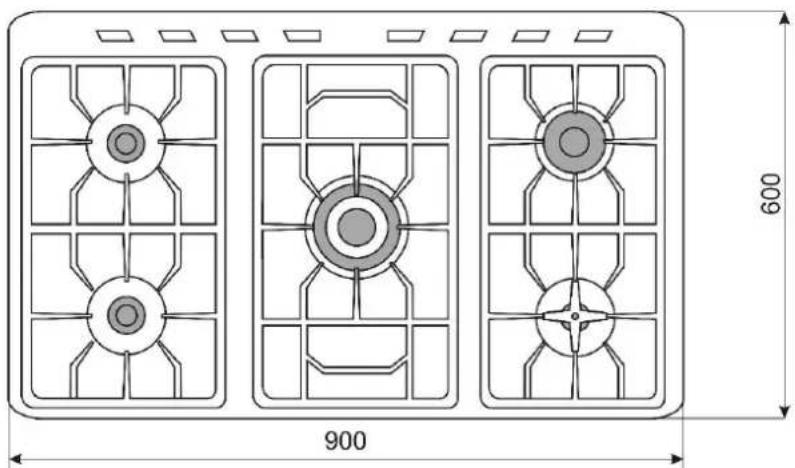
natural_image
Technical diagram of three identical fan-shaped components with internal grid patterns, labeled 900 and 600 (no text or symbols on the components themselves)natural_image
Close-up of a metallic mechanical component with threaded end and shaft (no visible text or symbols)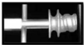
natural_image
Close-up of a metallic mechanical component with threaded end and flange (no visible text or symbols)- 2.
natural_image
Close-up of a mechanical component with a white arrow pointing to a raised shaft (no visible text or symbols)natural_image
Close-up of mechanical components with no visible text or symbols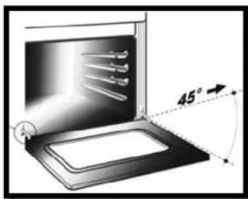
natural_image
Diagram of a door with ventilation slots and a curved line indicating a measurement or inspection (no text or symbols present)ЗМИНА ЛАМПОЧКИ
УВАГА!
РЕГУЛЮВАННЯ ПОЛУМЯ
- див. мал. XV
- KOMPLETACJA
- UWAGA!
- GENERAL SAFETY INSTRUCTIONS
- ATTENTION!
- USER TIPS
- BEFORE FIRST USE
- COMPLETION
- VIEW OF THE MAIN BOARD
- Burners control - see Fig. V
- Position 1 – Gas supply to the burner closed
- Position 2 - Starting
- Position 3 - Maximum flame
- Position 1 - Oven off
- Position 2 - Defrosting
- Position 3 – Convection Air
- Position 4 - Upper and bottom oven heaters on - traditional baking
- Position 5 – Upper heater on
- Position 6 – Bottom heater on
- Position 7 - Rotisserie toasting function on
- Using the rotisserie
- OVEN TIMER USER'S MANUAL
- Power up
- Manual mode
- Time of day adjustment
- Adjusting the buzzer alarm
- Cancelling the buzzer sound
- Automatic cooking program
- In case of mains power loss
- Adjusting the buzzer tone:
- APPLIANCE SETTING
- Selection of burners
- CLEANING AND MAINTENANCE
- CHANGE OF A LIGHT BULB
- TRANSPORT AND STORAGE
- INSTRUCTIONS FOR THE INSTALLER
- CONNECTION BY FLEXIBLE HOSE
- Natural gas connection
- Connection to liquid gas
- ATTENTION! CONNECTION BY RUBBER HOSES COMPLIANT WITH CURRENT REGULATIONS IS ONLY ALLOWED IF THE ENTIRE LENGTH OF THE HOSE IS POSSIBLE TO CONTROL
- REPLACING NOZZLES
- FLAME ADJUSTMENT
- ELECTRICAL CONNECTION
- COMMON FAULTS
- TECHNICAL PARAMETERS
- Energy saving tips
- Ravanson®
- ЗМИНА ЛАМПОЧКИ
- УВАГА!
- РЕГУЛЮВАННЯ ПОЛУМЯ
Brand : Ravanson
Model : KWGE-K90
Category : Cooker