CA-1803BT Athos - Car alarm Jablotron - Free user manual and instructions
Find the device manual for free CA-1803BT Athos Jablotron in PDF.


| Product Type | Car Alarm System |
| Brand | Joblotron |
| Model | CA-1803BT Athos |
| Connectivity | Bluetooth |
| Power Supply | 12V DC (vehicle battery) |
| Dimensions (Control Unit) | Approx. 120 x 80 x 30 mm |
| Weight (Control Unit) | Approx. 200 g |
| Remote Range | Up to 100 meters (line of sight) |
| Bluetooth Range | Up to 10 meters |
| Key Functions | Remote lock/unlock, arm/disarm, panic alarm, trunk release |
| Alarm Types | Shock sensor, door trigger, ignition trigger |
| Two-Way Communication | Yes (remote confirms status) |
| LED Indicator | Red LED on dashboard or control unit |
| Smartphone Control | Via Bluetooth app (compatible with iOS and Android) |
| Installation | Professional installation recommended |
| Battery for Remote | CR2032 (replaceable) |
| Operating Temperature | -20°C to 60°C |
| Warranty | 1 year limited |
Frequently Asked Questions - CA-1803BT Athos Jablotron
User questions about CA-1803BT Athos Jablotron
0 question about this device. Answer the ones you know or ask your own.
Ask a new question about this device
Download the instructions for your Car alarm in PDF format for free! Find your manual CA-1803BT Athos - Jablotron and take your electronic device back in hand. On this page are published all the documents necessary for the use of your device. CA-1803BT Athos by Jablotron.
USER MANUAL CA-1803BT Athos Jablotron
Installation manual: CA-1803BT "Athos"
Before installation
This is the basic version of the installation manual and programming sequences. On the web site www.jablotronalarms.com in the download section you can find a full version of this manual or you can find it included in the installation kit on CD / DVD. If you have no experience with CA-1803 installation, we recommend you to read the extended version of the manual to know all the parameters well.
The immobilizer relay contact of car alarm is connected only in disarmed mode and if the ignition is on. Do not block circuits that are under voltage while the ignition is off. It could cause a serious damage of the vehicle.
The car alarm should only be installed by a professional installer. It is suitable for cars with a dashboard voltage supply of 12V or 24V with a negative ground connection. During the first power-up, the value of supply voltage is read and the inputs are set to default settings. The alarm is designed to be installed inside the car.
For cars with a voltage supply of 24V, the following restrictions apply to car alarm installation:
- It is not possible to connect a hands-free set of type HF-03.
- When used for acoustic signalling, the SIR output is switched to the power supply voltage. Consequently, this output switches to 24V, so it is necessary to use a siren of type SA-606-24V instead of the SA-530 which is supplied in the standard package. In this case it is necessary to set the confirmation beeps to 100 ms.
Configuration table
| SIM entry* SMS instruction Text Description | ||
| RESET EN 1 (After which, the entry is erased from the SIM) | MASTER RESET EN 1 Mode setting. RESET 1 = alarm has its own remote control and provides signals for central locking. RESET 2 = alarm is operated by an original remote controller for central locking. RESET 3 = GSM pager for cars with an installed car alarm. Performing the RESET instruction is indicated by 4 beeps. Consequently, all settings, enrolled remote controllers and wireless detectors will be erased. | |
| Not applicable | MASTER UC uuuu | User code setting – the code allows you to operate the alarm remotely via SMS from unauthorized phones. uuuu is a new user code, 4 to 8 letters (A–Z & 0–9, case insensitive). Factory default user code is USER |
| Not applicable | MASTER MC xxxx | Master code setting –xxxx is a new master code (A–Z & 0–9, case insensitive). The code allows you to change the maintenance settings for the car alarm. Factory default master code is MASTER |
| TELn xx...x | MASTER TELn xx...x Setting of phone numbers to report alarms to n = 1 to 4 | |
| DIALn xx...x | MASTER DIALn xx...x Setting the phone numbers to dial using Hands free. n = A, B, 1, 2 | |
| DIP abcdefghij | MASTER DIP abcdefghij DIP parameter entry – see the DIP table | |
| SET abcdefghij | MASTER SET abcdefghij SET parameter entry – see the SET table | |
DIP parameters
| DIP | Description | |
| 0 1 | ||
| A | 0 = silent arming/disarming without siren chirps1 = 10 ms siren chirps when arming/disarming (non backed-up siren)2, 3, 4 ... 9 = siren chirps when arming/disarming (a siren of another type) lasting 20, 30, 40, 50, 100, 200, 300 or 500 ms | |
| B | Silent alarm | Audible alarm |
| C | SMS alarm report only | SMS alarm report and siren sound phone call |
| D | SMS remote control not confirmed by SMS reply | SMS remote control instructions confirmed by SMS reply |
| E | 0 = arming control by dialling-in disabled1 = arming control by dialling from TEL1 enabled2 = arming control by dialling from TEL1 and TEL2 enabled3 = arming control by dialling from TEL1, TEL2 and TEL3 enabled4 = arming control by dialling from all TEL1 to TEL4 enabled | |
| F | Arming control by dialling in is not confirmed by SMS | Arming control by dialling in (see E) is confirmed by SMS to the phone which called the car alarm |
| G | User can not change SMS Texts | User can change SMS texts by TXT Sequence |
| H | REARM disabled | If the car is not entered within 1 minute after disarming, it will REARM |
| I | 0 = Immobilization by arming and by SMS instruction1 = Immobilization by arming and automatically 5 minutes after ignition is turned off (AUTOIMO) and also by SMS instruction2 = Immobilization only by SMS instruction3 = Immobilization and also by SMS instruction. If disarmed and ignition is turned off for more than 60 minutes the SMS STATUS is sent as an alert to possible forgotten arming. | |
| J | Self-location disabled | The car's location will be sent by SMS after an IMO instruction has been performed.or if the car stops after an immobilizationSMS instruction |
Bold marked values = factory default
Steps to enroll RC-8x controllers:
- The car alarm should be disarmed, with the ignition on.
- Send the SMS instruction MASTER LEARN RC
- The car alarm beeps 3 times and an LED starts to flash.
- The RC-8x controller is enrolled by pressing buttons 🔒 and
simultaneously for approx. 3 sec. A siren chirp confirms the enrollment. By enrolling the first remote control all other remote controls previously enrolled will be erased (so enroll all the controllers intended for use, one by one).
- Exit enrollment by turning the ignition off. The alarm confirms the enrollment by sending an SMS message to authorized phones TEL1 to TEL4.
SET parameters
| SET | Description | |
| 0 | 1 | |
| A | 0 = open door signalling and INP activation while arming are both disabled1 = open door signalling and INP activation while arming are both enabled2 = INP activation while arming enabled, open door signalling enabled with a 10 second delay3 = INP activation while arming enabled, open door signalling disabled | |
| B | Voltage detector disabled | Voltage-drop detector enabled |
| C | lock / unlock signal duration (Reset 1)0 = 0.5 / 0.5 sec (suitable for electromagnetic locks)1 = 4 / 4 sec (suitable for pneumatic locks)2 = 60 / 0.5 sec (suitable for automatic window closing) | |
| D | DOOR input logic:1 = activated by falling edge (grounding)2 = activated by rising edge (disconnecting from GND) | |
| E | INP1 logic:1 = activated by falling edge (grounding)2 = activated by rising edge (disconnecting from GND) | |
| F | INP2 logic:0 = activated by falling edge (grounding), it triggers an alarm also if disarmed (24 hour reaction)1 = activated by falling edge (grounding)2 = activated by rising edge (disconnecting from GND) | |
| G | Central locking input logic: (Reset 2)1 = activated by falling edge (grounding)2 = activated by rising edge (disconnecting from GND) | |
| H | 0 = confirmation by turn lights for disarming is needed (Reset 2)1 = confirmation by turn lights for arming and disarming is needed2= confirmation by turn lights for arming and disarming is not needed so INP1 can be used as an alarm input | |
| I | When armed, no monitoring of GPS location changes | GPS location changes are monitored when armed |
| J | 0 = AUX output is a bus for communication with CR-11A modules1 = AUX output provides power for external sensors | |
Bold marked values = factory default
Steps to enroll I detectors:
- The car alarm should be disarmed, ignition on.
- To enroll the internal detectors, send the SMS command MASTER LEARN INT (To enroll the external detectors, send the SMS command MASTER LEARN EXT)
- The car alarm beeps 3 times and an LED starts to flash.
- You can enroll a new detector to the system by inserting its batteries. If you enroll a first detector, you will erase all detectors from the associated groups (enroll all of them, which will be used in the group in sequence).
- Exit enrollment by turning the ignition off. The alarm confirms enrollment by sending an SMS message to authorized phones TEL1 to TEL4.
Functions related to GPS
Location detection using GPS
An example of an instruction sent from an authorized phone: GPS An example of response: Car alarm reports: Location:
(GMT:3.12.10:35) 50*43.495N;15*11.253E;515;50, Time:3.12.05 11:35
(GMT:3.12.10:35) Greenwich Mean Time (mean meridian)
515 altitude (approximated)
50
current
Time:3.12.05 11:35 current local time
Time zone setting
To adjust the time information to local time, time zone setting is possible. The car alarm adds/subtracts the time shift, expressed in hours, to the GMT time (for middle Europe: +2 hours in summer time, +1 hour in winter time).
Instruction: MASTER TIME ±xy
xy is the time shift in hours -3,-2 ...+1,+2 relative to GMT
MASTER TIME GSM
turns on automatic setting via incoming SMS.
Integrated Bluetooth module (BT)
When disarmed and with the ignition key on, the car alarm sends GPS coordinates via the BT which can be used for navigation. The car alarm authorization code for device-pairing is 0000. The ignition key must be on during the pairing process.
Internet remote access
The web site www.GSMLink.cz enables car alarm remote control (to users) and setting (to installers).
To get internet access to an installed and powered car alarm you will first be asked to register your car alarm on the first page. You will find a unique registration code for your car alarm on the warranty card.
Additional features
Pre-paid SIM card balance
It is recommended not to use prepaid cards in the car alarm. If you have no other choice than prepaid cards, you can enable the CREDIT instruction by the following sequence:
MASTER CREDIT uuu..u xx yyy zz
where: uuu...u is the provider's code to obtain the balance
xx is the time period (in days) for regular checking
yyy is the threshold level below which the balance is reported to the user (TEL1)
zz is the position of the first digit of the balance in the reply SMS from the provider
- After this sequence has been sent once, the car alarm will check the balance automatically every xx days and if the balance is lower than yyy the user will be notified (TEL1)
- If the CREDIT instruction is enabled in the above way, the user can also obtain the current balance by the instruction CREDIT
- To disable the automatic balance checking set the time period "xx" to 00.
Reset GSM
If you need to disconnect and then reconnect the GSM module to the GSM network, then use the command "MASTER RESET GSM".
This does not affect any settings and velocity typically used for GPRS activation or charging up credit. This command always requires the Master code.
Service instruction
The DINFO instruction allows you to obtain current settings, information about the quality of the GSM signal, the registration code for GSMLink devices and some other parameters. This command always requires the Master code.
Example of instruction: MASTER DINFO
Example of response: Car alarm reports: CA-1803A, SN:123456,
SV:01, LV:03, RK:ABCDE-12345-FG67, R:01, GSM:25,GPS:5,
Time:3.2.06 11:35
| CA-1803A | car alarm version |
| SN:123456 | identification number of the product |
| SV:01 | software version |
| LV:03 | language version |
| RK: ABCDE-12345-FG67 | registration code for GSMLink |
| R:01 | current Reset mode of the device |
| GSM:25 | instant quality of GSM signal (ranging from 0 to 32 (best)) |
| GPS:5 | number of visible satellites (0-16) |
Specification
| Power supply | 12/24V DC (8-32V) |
| Stand-by consumption | max. 20 mA |
| Immobilization | 8A permanently, 12A intermittently |
| Complies with | ECE Regulation No. 97.00 |
| Can be operated according to ERC/DEC98(20,21), ERC REC 70-03 | |
| Safety | EN 60950-1 |
| EMC | EN 55022, EN 50130-4 |
| Radio interference | ETSI EN 301 419-1, EN 301 511, ETSI EN 300 220 |
| ETSI EN 300 328 | |

97 RAI-01 4532

JABLOTRON ALARMS a.s. hereby declares that the CA-1803BT is in compliance with the essential requirements and other relevant provisions of Directive 1999/5/EC and 1995/56/EC The original of the conformity assessment can be found at www.jablotron.com, Technical Support section

Note: Although this product does not contain any harmful materials we suggest you return the product to the dealer or directly to the producer after use.
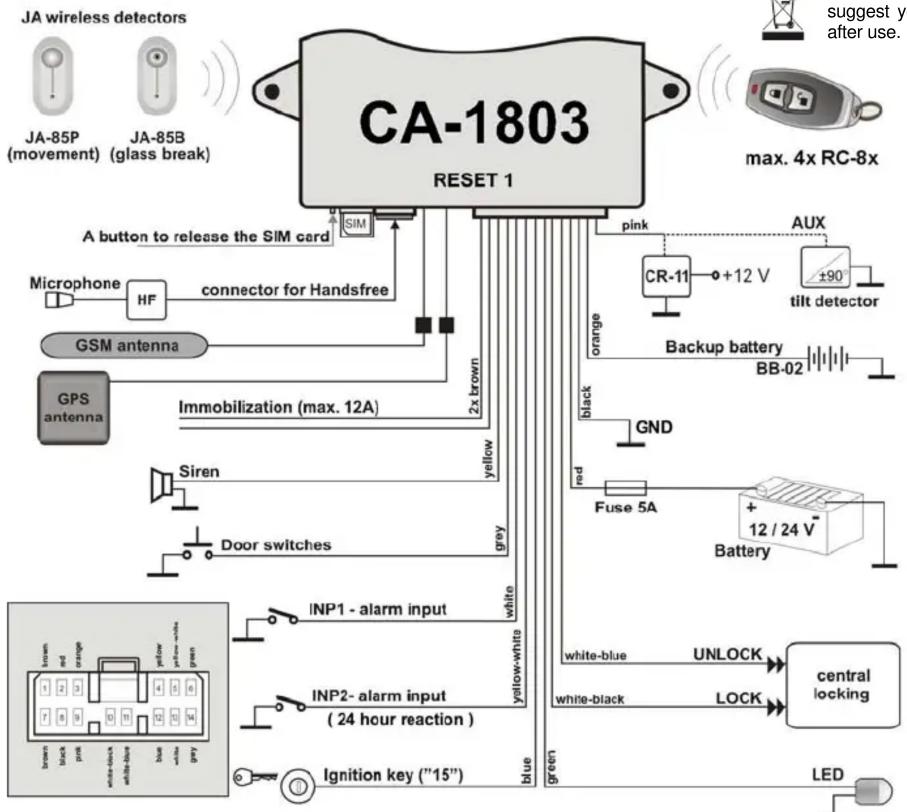
flowchart
graph TD
    A["CA-1803 RESET 1"] --> B["A button to release the SIM card"]
    A --> C["Microphone"]
    A --> D["GSM antenna"]
    A --> E["GPS antenna"]
    A --> F["Immobilization (max. 12A)"]
    A --> G["Siren"]
    A --> H["Door switches"]
    A --> I["INP1 - alarm input"]
    A --> J["INP2 - alarm input (24 hour reaction)"]
    A --> K["Ignition key ("15")"]

    L["CR-11"] --> M["+12 V"]
    N["AUX"] --> O["+90 V"]
    P["Battery"] --> Q["12 / 24 V"]
    R["UP"] --> S["UP"]
    T["USB"] --> U["USB"]
    V["LED"] --> W["LED"]

    X["Black"] --> Y["red"]
    Z["Orange"] --> AA["orange"]
    AB["Blue"] --> AC["green"]

    AD["Pin 2x brown"] --> AE["2x brown"]
    AF["Pin 2x yellow"] --> AG["yellow"]
    AH["Pin 2x gray"] --> AI["yellow-white"]
    AJ["Pin 2x blue"] --> AK["yellow-white"]
    AL["Pin 2x black"] --> AM["yellow-black"]
    AN["Pin 2x white"] --> AO["yellow-white"]
    AP["Pin 2x black"] --> AQ["yellow-black"]
    AR["Pin 2x black"] --> AS["yellow-black"]
    AT["Pin 2x black"] --> AU["yellow-black"]
    AV["Pin 2x black"] --> AW["yellow-black"]
    AX["Pin 2x black"] --> AY["yellow-black"]
    AZ["Pin 2x black"] --> BA["yellow-black"]
    BB["Pin 2x black"] --> BC["yellow-black"]
    BD["Pin 2x black"] --> BE["yellow-black"]
    BF["Pin 2x black"] --> BG["yellow-black"]
    BH["Pin 2x black"] --> BI["yellow-black"]
    BJ["Pin 2x black"] --> BK["yellow-black"]
    BL["Pin 2x black"] --> BM["yellow-black"]
    BN["Pin 2x black"] --> BO["yellow-black"]
    BP["Pin 2x black"] --> BP["yellow-black"]
    BPB["Pin 2x black"] --> BP["Battery"]

    style A fill:#f9f,stroke:#333
    style B fill:#ccf,stroke:#333
    style C fill:#cfc,stroke:#333
    style D fill:#fcc,stroke:#333
    style E fill:#cff,stroke:#333
    style F fill:#ffc,stroke:#333
    style G fill:#fcc,stroke:#333
    style H fill:#fcc,stroke:#333
    style I fill:#fcc,stroke:#333
    style J fill:#fcc,stroke:#333
    style K fill:#fcc,stroke:#333
    style L fill:#fcc,stroke:#333
    style M fill:#fcc,stroke:#333
    style N fill:#fcc,stroke:#333
    style O fill:#fcc,stroke:#333
    style P fill:#fcc,stroke:#333
    style Q fill:#fcc,stroke:#333
    style R fill:#fcc,stroke:#333
    style S fill:#fcc,stroke:#333
    style T fill:#fcc,stroke:#333
    style U fill:#fcc,stroke:#333
    style V fill:#fcc,stroke:#333
    style W fill:#fcc,stroke:#333
    style X fill:#fcc,stroke:#333
    style Y fill:#fcc,stroke:#333
    style Z fill:#fcc,stroke:#333
    style AA fill:#fcc,stroke:#333
    style AB fill:#fcc,stroke:#333
    style AC fill:#fcc,stroke:#333
    style AD fill:#fcc,stroke:#333
    style AE fill:#fcc,stroke:#333
    style AF fill:#fcc,stroke:#333
    style BB fill:#fcc,stroke:#333
    style BC fill:#fcc,stroke:#333
GSM car alarm CA-1803BT „Athos“ 2/2 MHF58202
JABLOTRON
JABLOTRON ALARMS a.s.
Pod Skalkou 4567/33
46601 Jablonec nad Nisou
Czech Republic
Tel.: +420 483 559 911
Fax: +420 483 559 993
Internet: www.jablotron.com
- Installation manual: CA-1803BT "Athos"
- Before installation
- Steps to enroll RC-8x controllers:
- Steps to enroll I detectors:
- Functions related to GPS
- Location detection using GPS
- Time zone setting
- Integrated Bluetooth module (BT)
- Internet remote access
- Additional features
- Pre-paid SIM card balance
- MASTER CREDIT uuu..u xx yyy zz
- Reset GSM
- Service instruction
- Example of instruction: MASTER DINFO
Brand : Jablotron
Model : CA-1803BT Athos
Category : Car alarm