JA-89P - Security Camera Jablotron - Free user manual and instructions
Find the device manual for free JA-89P Jablotron in PDF.


| Product Type | Wireless Outdoor PIR Detector |
| Brand | Joblotron |
| Model | JA-89P |
| Dimensions | 198 x 80 x 108 mm |
| Weight | 0.3 kg (approx.) |
| Power Source | Lithium AA 3.6 V (LS(T)14500) |
| Battery Life | Approx. 3 years (120 sec sleep mode) |
| Communication Band | 868 MHz |
| Communication Range | 300 m (open area) |
| Detection Coverage | 10 m / 90°; 14 segments |
| Installation Height | 0.8 - 1.2 m |
| Ingress Protection | IP54 |
| Operating Temperature | -20°C to +50°C |
| Security Grade | Grade 2 (EN 50131-1) |
| Sensor Type | Dual-zone PIR (AND logic) |
| Tamper Protection | Front and rear tamper switches |
| Sleep Mode | 5 or 120 seconds configurable |
| LED Indicator | On/Off for test mode |
| Included Accessories | Drilling template, pole straps, masking strips |
| Installation | Wall or pole mount (43-48 mm) |
Frequently Asked Questions - JA-89P Jablotron
User questions about JA-89P Jablotron
0 question about this device. Answer the ones you know or ask your own.
Ask a new question about this device
Download the instructions for your Security Camera in PDF format for free! Find your manual JA-89P - Jablotron and take your electronic device back in hand. On this page are published all the documents necessary for the use of your device. JA-89P by Jablotron.
USER MANUAL JA-89P Jablotron
The JA-89P wireless outdoor PIR detector
The JA-89P is an outdoor intruder detector designed to detect human body movement in a protected area. It supplements a double-zone PIR sensor produced by Optex with a Jablotron transmitter enabling the sensor to be used within JA-80 OASiS systems. Both the PIR sensor and the transmitter are powered by a lithium battery. Sharing the power source allows low voltage reports to be transmitted to the control panel in the standard way. The detector is equipped with two tamper sensors (front and back) capable of signalling that the detector's cover has been opened or that the detector has been torn off its position. Self testing is performed automatically on a regular basis including reporting detector status to the control panel. These properties make the JA-89P a standard component of Jablotron's OASiS system.
Installation
Choose a proper place for detector installation according to the following:
- Install the detector perpendicular to the ground to make the upper detection area parallel to the ground.
- The installation height is 0.8 - 1.2 m.
- Mount the detector so that the majority of traffic flow is across the detection pattern.
- Avoid positions where moving or waving objects like cars, plants or trees might appear in the detection area. Avoid positions where the detector can be affected by strong light sources, e.g. reflected sunlight.
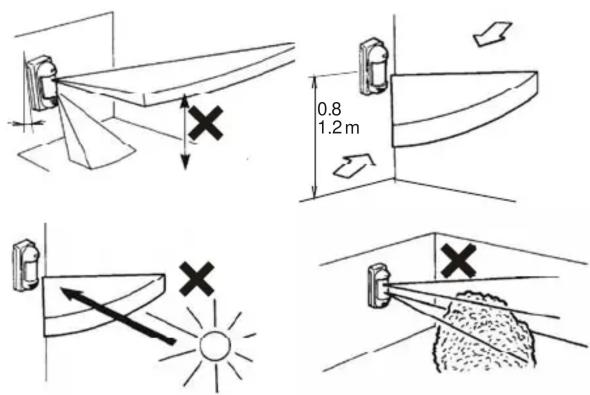
Installation, step by step:
- Unscrew the lock screw located on the bottom side of the upper cover and remove the cover.
- Unscrew the screws fastening the optical part of the detector and remove this part by tipping it up.
- Disconnect the rear tamper sensor cable.
- You can fix the detector to an even plate using either two non-skimmed holes or four skimmed holes located in the corners of the rear cover.
- Use the drilling template supplied in the package for marking all the spots relevant to detector fixing as well as to fixing the rear tamper magnet.
- Alternatively, you can install the detector on a pole ( 43 – 48 mm) using straps supplied with the package. However, this way of installation disables the rear tamper switches (tear-off signalling) – you have to short out the transmitter tamper inputs using a jumper.
- After the bottom plastic cover has been fixed, insert the rear TAMPER connector into the terminal marked TMP IN.
Caution: Never touch the detection surface of the PIR sensor.

Powering up and enrollment
The transmitter of wireless communication signals is located below the detector's optical part. Study the installation manual of the receiver (control
panel) first to learn how to enter enrollment mode. Only use a lithium battery of type AA 3.6 V. The correct battery position is marked on the battery holder. After a battery is inserted the transmitter sends an enrollment signal to the receiver. The control panel – if used as a receiver – must be in enrollment mode. You can use the detector's switch No. 2 to configure control panel reactions (ON = Instant, OFF = Delayed). Switch No. 1 should be OFF.

Optical part adjustment
The detector's optical part contains two PIR sensors each having its own detection plane. The detection area angle of the lower sensor can be configured over a wide range. The sensors operate with AND logic: an alarm signal is generated only if both sensors are triggered (if both detection planes are crossed). You can adjust the detection plane slope of the lower sensor by a shifting lever according to the picture below.
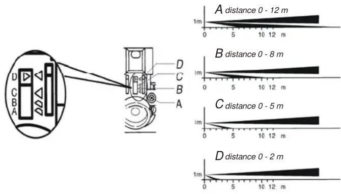
The following table provides a summary of detection length characteristics:
| Position | The lower sensor max. detection length | |
| Standard See note below: | ||
| A 10 m | 8.0 to 12.0 m | |
| B | 8 m | 6.0 to 10.0 m |
| C | 5 m | 4.0 to 5.5 m |
| D | 2 m | 1.5 to 2.5m |
Note: The maximum detection length of the lower detection plane may vary as above due to environmental thermal conditions. This must be taken into consideration during detection range adjustment.

The detection area angle is 90^ . The direction can be adjusted in 15^ steps by rotating the detector's plastic part. The detector lens covers the whole angle of 180^ - therefore it does not require any adjustment.
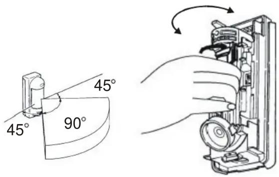
You can restrict the detection angle by adhesive masking strips supplied with the package. This way you can eliminate problematic parts of the detection area. The strips are to be stuck on the relevant lens segment from the inner side.
The PIR detection sensitivity can be configured by a 3-pole switch located under the upper sensor. The letters correspond to sensitivity levels as follows:
L low – applicable to bad conditions
M middle
H high
Other parameters can be configured using a DIP switch:
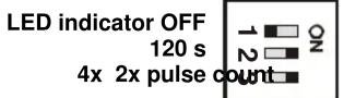
LED indicator ON
5 s battery saving timer
The LED indicator is to be used for PIR detector testing. For normal detector operation the indicator should be turned off in order to save the battery.
The JA-89P is capable of automatically switching to battery-save mode. Triggering a PIR sensor is signalled to the control panel after which the detector switches to sleep mode for a configurable time. During this time the detector ignores any further movement.
A filter for detector signalling can be established by setting a trigger counter. Either 2 or 4 triggering events (which have to be detected by both PIR sensors due to the AND logic) can be configured to cause signals to be sent to the control panel.
Testing operation
Turn the LED indicator on, set the battery-save timer to 5 seconds and close the detector. Every 5 seconds any movement in the detection area will be indicated by the LED indicator and the alarm information will be sent to the control panel. You should test both the sensitivity to movements in the detection area as well as the detector's insensitivity to any movement outside the area of protection. Take into consideration that the detection range may vary according to local conditions.
After finishing the test, it is recommended to turn off the LED indicator and set the battery-save mode duration to 120s.
Operation
The detector uses radio signalling for all types of detected events: movement detection, cover opening, tearing the detector off its position, and communication checking. The communication checking is automatically performed at 9 minute intervals for the system to test that all its devices are present and ready for operation.
Battery replacement
The detector monitors its battery voltage and if too low, a report is sent to the control panel to inform the installer or user. The detector continues to function. Battery replacement should not be delayed by more than one week.
Before battery replacement, you need to ensure that the receiver (control panel) is put into a state which permits opening the detector cover. Only use a lithium battery of type AA 3.6 V. After closing the cover, the detector starts to operate in its normal mode.
Note:
The detector's LED flashes if you accidentally insert a low battery.
The detector will not work after an expired battery has been inserted.
Trouble-shooting
| Problem | Probable cause | Remedy |
| The detector makes false intrusion alarms. | Lower detection area is unnecessarily long. | Set the detection area properly. |
| The detector is exposed to direct/ reflectioned light (sun light, car lights etc.). | Remove the reflector, mask the area exposed to the reflection of light or change the detector position. | |
| There is a moving object in the area (laundry on the clothes-line, plants etc.) | Remove the moving object or change the detector position. |
| Occasionally no | The detection area is too close to the detector. | Set the detection area properly. |
| Sensitivity is set to low (L). | Change sensitivity to medium (M) or high (H). | |
| The detector is in battery-save mode. | While testing operation, set the battery-save timer to 5 seconds. | |
| Detector ignores any movements. | Low battery. Replace the battery. | |
| LED does not light. Turn the LED switch ON. | ||
| LED indicator lights but there is no reaction in the control panel. | The control panel is out of range, check the battery, try to reposition detector or control panel. | |


Dimensions
Technical specifications
| Voltage: | Lithium battery type LS(T)14500 (3,6V AA) |
| Typical battery lifetime | approx. 3 years (120 sec sleep mode) |
| Communication band | 868 MHz |
| Communication range | approx. 300 m (open area) |
| Specification of the Optex VX 402R detector | |
| Coverage | 10 m / 90°; 14 segments |
| Installation height | 0.8 – 1.2 m |
| Detected speeds | 0.3 – 1.5 ms ^-1 |
| Battery saving timer | either 5 or 120 seconds |
| LED indicator | only in test mode |
| Operational environment class | IV, according to EN 50131-1 |
| Security grade | 2, according to EN 50131-1 |
| Operational temperature range | -20°C to +50°C |
| Enclosure | IP54 |
| Maximum relative humidity | 95% |
| Dimensions | 198 x 80 x 108 mm |
Can be operated according to
ERC REC 70-03
Security grade
2, according to EN 50131-1, CLCITS 50131-2-2, EN 50131-5-3

Jablotron Ltd. hereby declares that the JA-89P is in compliance with the essential requirements and other relevant provisions of Directive 1999/5/ES. The original of the conformity assessment can be found on the web site www.jablotron.com, Technical Support section.

Note: Dispose of batteries safely depending on battery type and local regulations. Although this product does not contain any harmful materials we suggest you return the product to the dealer or directly to the manufacturer after use.

Pod Skalkou 33
466 01 Jablonec nad Nisou
Tel.: 483 559 911
fax: 483 559 993
Internet: www.jablotron.com
Brand : Jablotron
Model : JA-89P
Category : Security Camera