
NSX-MT520 - CD Player AIWA - Free user manual and instructions
Find the device manual for free NSX-MT520 AIWA in PDF.


| Product Type | Compact Disc Stereo System |
| Brand | Aiwa |
| Model | NSX-MT520 |
| Main Unit Dimensions (W x H x D) | 260 x 329.1 x 344.5 mm (10 1/4 x 13 x 13 5/8 in) |
| Main Unit Weight | 7.6 kg (16 lb 12 oz) |
| Power Requirements | 120 V AC, 60 Hz |
| Power Consumption | 160 W |
| Speaker System Model | SX-NA502 |
| Speaker Type | 3-way, bass reflex (magnetic shielded) |
| Speaker Impedance | 6 ohms |
| Speaker Dimensions (W x H x D) | 235 x 324 x 250 mm (9 3/8 x 12 7/8 x 9 7/8 in) |
| Speaker Weight | 3.3 kg (7 lb 4 oz) |
| FM Tuning Range | 87.5 MHz to 108 MHz |
| AM Tuning Range | 530 kHz to 1710 kHz (10 kHz step) / 531 kHz to 1602 kHz (9 kHz step) |
| Amplifier Power Output (Front) | 40 W + 40 W (6 ohms, 50 Hz - 20 kHz, THD < 1%) |
| Amplifier Power Output (Surround) | 20 W + 20 W (8 ohms, 50 Hz - 20 kHz, THD < 1%) |
| Amplifier Power Output (Center) | 20 W (8 ohms, 50 Hz - 20 kHz, THD < 1%) |
| CD Player Laser | Semiconductor laser (λ = 780 nm) |
| CD Player D/A Converter | 1-bit dual |
| CD Player Signal-to-Noise Ratio | 85 dB (1 kHz, 0 dB) |
| Cassette Deck Track Format | 4 tracks, 2 channels stereo |
| Cassette Deck Frequency Response | 50 Hz - 15000 Hz |
| Dolby Pro Logic | Yes (Normal, Phantom, 3 Stereo modes) |
| DSP Surround Modes | Disco, Live, Movie, Hall + 4 manual modes |
| Graphic Equalizer | 5 presets (Rock, Pop, Jazz, Classic, Latin) + 4 manual modes |
| BBE System | Yes (3 levels) |
| Super T-BASS System | Yes (3 levels) |
| Karaoke Functions | Vocal Fader, Auto Vocal Fader, Multiplex, Auto Multiplex |
| Timer / Sleep Timer | Yes (programmable timer, sleep timer up to 240 min) |
| Connections | VIDEO/AUX (RCA), MD (RCA), MIC 1/2 (3.5mm), 5.1CH Input, Line Out, Subwoofer Out, CD Digital Out (Optical) |
| Remote Control | Yes (with batteries) |
| Safety Features | Polarized plug, ventilation requirements, condensation warning, outdoor antenna grounding |
| Maintenance | Clean cabinet with soft dry cloth; clean tape heads every 10 hours; demagnetize heads after 20-30 hours; clean CD from center out |
Frequently Asked Questions - NSX-MT520 AIWA
User questions about NSX-MT520 AIWA
0 question about this device. Answer the ones you know or ask your own.
Ask a new question about this device
Download the instructions for your CD Player in PDF format for free! Find your manual NSX-MT520 - AIWA and take your electronic device back in hand. On this page are published all the documents necessary for the use of your device. NSX-MT520 by AIWA.
USER MANUAL NSX-MT520 AIWA
COMPACT DISC STEREO SYSTEM SISTEMA ESTEREO CON REPRODUCTOR DE DISCOS COMPACTOS CHAINE STEREO AVEC LECTEUR DE DISQUES COMPACTS
NSX-MT520
OPERATING INSTRUCTIONS MANUAL DE INSTRUCCIONES MODE D'EMPLOI
En (English)
E (Español)
F (Français)
For assistance and information
call toll free 1-800-BUY-AIWA
(United States and Puerto Rico)
WARNING
TO REDUCE THE RISK OF FIRE OR ELECTRIC SHOCK, DO NOT EXPOSE THIS APPLIANCE TO RAIN OR MOISTURE.
CAUTION
RISK OF ELECTRIC SHOCK DO NOT OPEN

"CAUTION: TO REDUCE THE RISK OF ELECTRIC SHOCK, DO NOT REMOVE COVER (OR BACK). NO USER-SERVICEABLE PARTS INSIDE. REFER SERVICING TO QUALIFIED SERVICE PERSONNEL."
Explanation of Graphical Symbols:
The lightning flash with arrowhead symbol, within an equilateral triangle, is intended to alert the user to the presence of uninsulated "dangerous voltage" within the product's enclosure that may be of sufficient magnitude to constitute a risk of electric shock to persons.

The exclamation point within an equilateral triangle is intended to alert the user to the presence of important operating and maintenance (servicing) instructions in the literature accompanying the appliance.
Owner's record
For your convenience, record the model number and serial number (you will find them on the rear of your set) in the space provided below. Please refer to them when you contact your Aiwa dealer in case of difficulty.
| Model No. | Serial No. (Lot No.) |
| CX-NMT520 | |
| SX-NA502 | |
| SX-R275 | |
| SX-C605 |
PRECAUTIONS
Read the Operating Instructions carefully and completely before operating the unit. Be sure to keep the Operating Instructions for future reference. All warnings and cautions in the Operating Instructions and on the unit should be strictly followed, as well as the safety suggestions below.
Installation
1 Water and moisture — Do not use this unit near water, such as near a bathtub, washbowl, swimming pool, or the like.
2 Heat — Do not use this unit near sources of heat, including heating vents, stoves, or other appliances that generate heat. It also should not be placed in temperatures less than 5°C (41°F) or greater than 35°C (95°F).
3 Mounting surface — Place the unit on a flat, even surface.
4 Ventilation — The unit should be situated with adequate space around it so that proper heat ventilation is assured. Allow 10 cm (4 in.) clearance from the rear and the top of the unit, and 5 cm (2 in.) from each side.
- Do not place the unit on a bed, rug, or similar surface that may block the ventilation openings.
- Do not install the unit in a bookcase, cabinet, or airtight rack where ventilation may be impeded.
5 Objects and liquid entry — Take care that objects or liquids do not get inside the unit through the ventilation openings.
6 Carts and stands — When placed or mounted on a stand or cart, the unit should be moved with care.
Quick stops, excessive force, and uneven surfaces may cause the unit or cart to overturn or fall.

7 Condensation — Moisture may form on the CD pickup lens when:
- The unit is moved from a cold spot to a warm spot
- The heating system has just been turned on
- The unit is used in a very humid room
- The unit is cooled by an air conditioner
When this unit has condensation inside, it may not function normally. Should this occur, leave the unit for a few hours, then try to operate again.
8 Wall or ceiling mounting — The unit should not be mounted on a wall or ceiling, unless specified in the Operating Instructions.
Electric Power
1 Power sources — Connect this unit only to power sources specified in the Operating Instructions, and as marked on the unit.
2 Polarization — As a safety feature, some units are equipped with polarized AC power plugs which can only be inserted one way into a power outlet. If it is difficult or impossible to insert the AC power plug into an outlet, turn the plug over and try again. If it still does not easily insert into the outlet, please call a qualified service technician to service or replace the outlet. To avoid defeating the safety feature of the polarized plug, do not force it into a power outlet.
3 AC power cord
- When disconnecting the AC power cord, pull it out by the AC power plug. Do not pull the cord itself.
- Never handle the AC power plug with wet hands, as this could result in fire or shock.
- Power cords should be firmly secured to avoid being severely bent, pinched, or walked upon. Pay particular attention to the cord from the unit to the power outlet.
- Avoid overloading AC power plugs and extension cords beyond their capacity, as this could result in fire or shock.
4 Extension cord — To help prevent electric shock, do not use a polarized AC power plug with an extension cord, receptacle, or other outlet unless the polarized plug can be completely inserted to prevent exposure of the blades of the plug.
5 When not in use — Unplug the AC power plug from the power outlet if the unit will not be used for several months or more. When the cord is plugged in, a small amount of current continues to flow to the unit, even when the power is turned off.
Outdoor Antenna
1 Power lines — When connecting an outdoor antenna, make sure it is located away from power lines.
2 Outdoor antenna grounding — Be sure the antenna system is properly grounded to provide protection against unexpected voltage surges or static electricity build-up. Article 810 of the National Electrical Code, ANSI/NFPA 70, provides information on proper grounding of the mast, supporting structure, and the lead-in wire to the antenna discharge unit, as well as the size of the grounding unit, connection to grounding terminals, and requirements for grounding terminals themselves.
Antenna Grounding According to the National Electrical Code
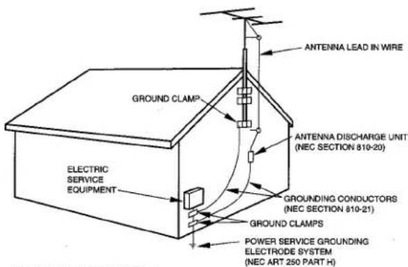
NEC-NATIONAL ELECTRICAL CODE
Maintenance
Clean the unit only as recommended in the Operating Instructions.
Damage Requiring Service
Have the units serviced by a qualified service technician if:
- The AC power cord or plug has been damaged
- Foreign objects or liquid have gotten inside the unit
- The unit has been exposed to rain or water
- The unit does not seem to operate normally
- The unit exhibits a marked change in performance
- The unit has been dropped, or the cabinet has been damaged DO NOT ATTEMPT TO SERVICE THE UNIT YOURSELF.
TABLE OF CONTENTS
PRECAUTIONS....1
PREPARATIONS
SETTING UP 3
REMOTE CONTROL....5
BEFORE OPERATION....6
SOUND
AUDIO ADJUSTMENTS 7
GRAPHIC EQUALIZER 8
DSP SURROUND 10
RADIO RECEPTION
MANUAL TUNING....11
PRESETTING STATIONS 12
TAPE PLAYBACK
BASIC OPERATIONS 13
CONTINUOUS PLAY 14
CD PLAYING
BASIC OPERATIONS ...... 15
PROGRAMMED PLAY 16
RECORDING
BASIC RECORDING.... 17
DUBBING A TAPE MANUALLY 18
DUBBING THE WHOLE TAPE 18
AI EDIT RECORDING 19
PROGRAMMED EDIT RECORDING.... 20
DOLBY PRO LOGIC
PARTS INDEX ...... Back cover
SETTING UP
The DOLBY PRO LOGIC system which is the biggest feature of this stereo system provides you with multi channel sound in your home.
Complete setting and connection of the main unit, supplied speakers, your TV and video equipment according to the following procedure.
Check your system and accessories
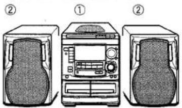
① CX-NMT520 Compact disc stereo cassette receiver
② SX-NA502 Front speakers

SX-R275

Surround speakers

SX-C605
Center speaker

Remote control

AM antenna
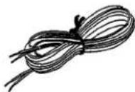
FM antenna
Operating Instructions, etc.
To achieve the optimum effects obtainable with the DOLBY PRO LOGIC system, it is important to position the speakers properly. Refer to the following illustration to find out the best location in your room.

flowchart
graph TD
    L["Device L"] -->|①| CX["NMT520"]
    CX -->|②| TV["TV"]
    TV -->|②| R["Device R"]
    R -->|①| S1["S"]
    S1 -->|③| DeviceS["Sensor S"]
    DeviceS -->|③| S2["S"]
    S2 -->|③| DeviceS2["S"]
    DeviceS2 -->|③| CXN["Device CX-NMT520"]
    CXN -->|①| L
    CXN -->|②| TV
    CXN -->|③| R
① Front speakers
② Center speaker
Position in the center of the two front speakers. In addition, position on or below the TV set, if connecting a TV set to the unit.
③ Surround speakers
Place the surround speakers directly to the side of or slightly behind the listening area. Align them horizontally, about 1 meter (3.2 feet) above ear height.
NOTE
- No sound is heard from the center and surround speakers when the DOLBY PRO LOGIC, the SURROUND system and the 5.1 CH (page 28) are set to off.
- The center speaker sounds when the DOLBY PRO LOGIC or the 5.1 CH (page 28) is set to on.
CONNECTIONS
Before connecting the AC cord
The rated voltage of your unit shown on the rear panel is 120 V AC. Check that the rated voltage matches your local voltage.
IMPORTANT
Connect the speakers, antennas, and all optional equipment first. Then connect the AC cord.

flowchart
graph TD
    A["Front speaker"] --> B["2"]
    B --> C["3 Surround speaker"]
    C --> D["4 Center speaker"]
    D --> E["5 Video equipment"]
    E --> F["6 Television"]
    F --> G["Main unit"]
    G --> H["AC cord"]
    H --> I["7 Front speaker"]
    J["FM antenna"] --> G
    K["AM antenna"] --> G
    L["Surround speaker"] --> M["3 Surround speaker"]
    style A fill:#f9f,stroke:#333
    style B fill:#ccf,stroke:#333
    style C fill:#cfc,stroke:#333
    style D fill:#fcc,stroke:#333
    style E fill:#cff,stroke:#333
    style F fill:#ffc,stroke:#333
    style G fill:#cfc,stroke:#333
    style H fill:#fcc,stroke:#333
    style I fill:#ffc,stroke:#333

1 Connect the supplied antennas.
Connect the FM antenna to FM 75 Ω terminals and the AM antenna to AM LOOP terminal.

2 Connect the front speakers.
The speaker placed on the right side of the unit facing you is "the right speaker" and another one is "the left speaker".

The cords with white stripes should be connected to + terminals and the other cords to - terminals.
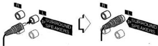
3 Connect the surround speakers.
Connect the surround speaker cords to SURROUND SPEAKERS terminals.
There is no difference between the surround speakers. Both speakers can be connected as R (right) or L (left).
4 Connect the center speaker.
Connect the center speaker cord to CENTER SPEAKER terminal.

5 Connect the video equipment.
Connect VIDEO/AUX jack of this unit to the audio output jack of the video equipment with an optional audio connecting cord.
6 Connect the Television to the video equipment.
Refer to the Operating Instructions of the connected equipment for details.
7 Connect the AC cord to an AC outlet.
To position the antennas
FM feeder antenna:
Extend this antenna horizontally in a T-shape and fix its ends to the wall.
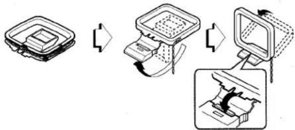
AM antenna:
Position to find the best possible reception.
To stand the AM antenna on a surface
Fix the claw to the slot.
flowchart
graph TD
    A["Top Box"] --> B["Down Arrow"]
    B --> C["Up Arrow"]
    C --> D["Down Arrow"]
    D --> E["Bottom Box"]
To mount the surround speakers on the wall
Mount each speaker on a spot that can hold its weight.

natural_image
Diagram showing a screw being inserted into a circular mechanical component with a downward arrow indicating force (no text or symbols present)NOTE
- Be sure to connect the speaker cords correctly. Improper connections can cause short circuits in SPEAKERS terminals.

- Do not leave objects generating magnetism, such as credit cards, near the speakers, as these objects may be damaged.
- Do not bring the FM antenna near metal objects or curtain rails.
- Do not bring the AM antenna near other optional equipment, the stereo system itself, the AC cord or speaker cords, since noise will be picked up.
- Do not unwind the AM antenna wire.
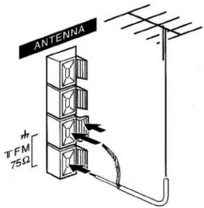
CONNECTING AN OUTDOOR ANTENNA
For better FM reception, use of an outdoor antenna is recommended.
Connect the outdoor antenna to FM 75 Ω terminals.
To connect other optional equipment → page 27 and 28.
REMOTE CONTROL
Inserting batteries
Detach the battery cover on the rear of the remote control and insert two R6 (size AA) batteries.
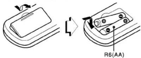
When to replace the batteries
The maximum operational distance between the remote control and the sensor on the main unit should be approximately 5 meters (16 feet). When this distance decreases, replace the batteries with new ones.
Using the remote control
The instructions in this manual refer mainly to the buttons on the main unit. Buttons on the remote control with the same names as those on the main unit can be used as well.
NOTE
- If the remote control is not going to be used for an extended period of time, remove the batteries to prevent possible electrolyte leakage.
• The remote control may not operate correctly when: - The line of sight between the remote control and the remote sensor inside the display window is exposed to intense light, such as direct sunlight
- Other remote controls are used nearby (those of a television, etc.)
BEFORE OPERATION
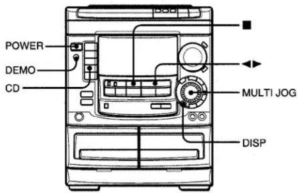
To turn the power on
Press one of the function buttons (TAPE, TUNER, VIDEO/AUX, CD, MD). Playback of the inserted disc or tape begins, or the previously tuned station is received (Direct Play Function).
POWER is also available.
When the unit is turned on, the disc compartment may open and close to reset the unit.
To turn the power off
Press POWER.
Flash windows
The windows on the top of the unit and the cassette decks light up or flash while the unit is being powered on.
To turn off the light of the top window, press ■ while pressing CD. To turn back on, repeat the above.
The light of the cassette decks cannot be turned off.
To dim the illumination of the display
1 Press DISP twice so that "DIMMER" is displayed.
2 Within 4 seconds, turn MULTI JOG to select the dimmer mode as follows.

DIMMER 0: The normal display.
DIMMER 1: The illumination of the display is dimmer than usual.
DIMMER 2: The illumination of the display is dimmer than DIMMER 1.
DIMMER 3: The illumination of the display is dimmer than DIMMER 2. The spectrum analyzer, the illumination on the buttons, and the windows on the top of the unit and the cassette decks light off.
To change the spectrum analyzer display
3 patterns of spectrum analyzer display can be shown.
Press DISP once, and turn MULTI JOG within 4 seconds to select the desired spectrum analyzer display.
Game Demo
When the AC cord is connected, the display window demonstrates the game Demo. When the power is turned on, the game Demo is overridden by the operation display. When the power is turned off, the game Demo is restored.
To cancel the game Demo
Press DEMO. To re-activate the game Demo, press DEMO again.
To play the game Demo
1 Press DEMO so that the game Demo displays.
2 Press ◀▶.
Three numbers on the display start to run.
3 Press ■ once.
The number on the left side stops.
4 Press ■ twice to stop the remaining two numbers.
Scoring:
20 points are given to start the game.
If all the numbers are equal, 50 points are added to the score.
If not equal, one point is subtracted.
If the gained points reach 9999, you win.
If the gained points fall to 0, you lose.
To reset the game Demo
Press DEMO twice, then press ◀►. The game starts again.
NOTE
- During playing the game Demo, ■ and ◀▶ are available only for the game Demo. Cancel the game Demo to use these buttons for the functions such as CD playing, etc.
- During the game Demo, some indicators unrelated with the actual operation light up on the display.
AUDIO ADJUSTMENTS

VOLUME
Turn VOLUME on the main unit, or press VOLUME on the remote control.
The volume level is displayed as a number from 0 to MAX (50). The volume level is automatically set to 20 when the power is turned off with the volume level set to 21 or more.
To change the left/right balance
Press MANUAL SELECT on the remote control. L/R is displayed for 2 seconds. Press ◀◀◀ DOWN or ▶▶▶ UP on the remote control within these 2 seconds.
- The DOLBY PRO LOGIC and the DOLBY DIGITAL SURROUND front speakers level is also changed. (See page 21 and 28)
BBE SYSTEM
The BBE system enhances the clarity of high-frequency sound. It also enriches the Karaoke function to make your voice sound clear and pleasant.
Press BBE.
Each time it is pressed, the level changes. Select one of the three levels, or the off position to suit your preference.

- The BBE system dose not perform while the 5.1 CH (page 28) is selected.
SUPER T-BASS SYSTEM
The T-BASS system enhances the realism of low-frequency sound.
Press T-BASS.
Each time it is pressed, the level changes. Select one of the three levels, or the off position to suit your preference.

NOTE
- Low frequency sound may be distorted when the T-BASS system is used for a disc or tape in which low frequency sound is originally emphasized. In this case, cancel the T-BASS system.
- When playing back a tape recorded with BBE, it is recommended that BBE be set to off to avoid distorted high frequency sound.
GRAPHIC EQUALIZER
SELECTING THE PROGRAMMED EQUALIZATION CURVE
This unit provides the following 5 different programmed equalization curves.
ROCK: Powerful sound emphasizing treble and bass
POP: More presence in the vocals and midrange
JAZZ: Accented lower frequencies for jazz-type music
CLASSIC: Enriched sound with heavy bass and fine treble.
LATIN: Accented higher frequencies for latin music.

Press GEQ, and turn MULTI JOG to select one of the programmed equalization curve within 4 seconds.
"GRAPHIC EQUALIZER" lights up.
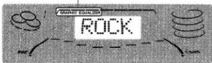
"GRAPHIC EQUALIZER" appears (except "GEQ OFF") and the GEQ mode is displayed cyclically as follows.

flowchart
graph LR
    A["ROCK"] --> B["POP"]
    B --> C["JAZZ"]
    C --> D["CLASSIC"]
    D --> E["LATIN"]
    E --> F["GEQ OFF (cancel)"]
    F --> G["M4"]
    G --> H["M3"]
    H --> I["M2"]
    I --> J["M1"]
    J --> K["Manual mode"]
    K -.-> L["Programmed mode"]
Using the headphones
Connect headphones to the PHONES jack with a standard stereo plug (ø6.3 mm, 1/4 inch).
No sound is output from the speakers while the headphones are plugged in.
- When the headphones are plugged in, the SURROUND system, the DOLBY PRO LOGIC and the 5.1 CH (page 28) do not function.
Sound adjustment during recording
The output volume and tone (except BBE) of the speakers or headphones may be freely varied without affecting the recording.
To display the current GEQ mode
Press GEQ. The current mode is displayed for 4 seconds.
To cancel the selected mode
Press GEQ, and turn MULTI JOG to select" GEQ OFF" within 4 seconds. "GRAPHIC EQUALIZER" disappears.
SETTING A NEW EQUALIZATION CURVE MANUALLY

The equalization curve can be customized to suit your preference.
1 Press GEQ LOW.
The lowest level frequency indicator flashes for 4 seconds.
2 Within 4 seconds, turn MULTI JOG to adjust the level of the lowest frequency.

3 Press GEQ HIGH.
The highest level frequency indicator flashes for 4 seconds.
4 Within 4 seconds, turn MULTI JOG to adjust the level of the highest frequency.

The frequency level indicators between the lowest and the highest are adjusted accordingly.
MEMORIZING THE NEW EQUALIZATION CURVES

Up to 4 customized equalization curves can be stored as the manual modes M1 - M4.
1 Set a new equalization curve with HIGH, LOW, and MULTI JOG.
See "SETTING A NEW EQUALIZATION CURVE MANUALLY". The created curve is displayed for 4 seconds.

2 Within 4 seconds, press ENTER.
"M 1" flashes on the display for 4 seconds.

natural_image
Black textured background with a white circular emblem in the center (no text or symbols)- If this step is not completed within 4 seconds, press GEQ first to display "GEQ ON". Then press ENTER within 4 seconds.
3 Within 4 seconds, turn MULTI JOG to select one of the manual modes M1 - M4 to store the curve.
4 Within 4 seconds, press ENTER.
The new equalization curve is stored.
To select the stored equalization curve
Press GEQ, and turn MULTI JOG to select one of the manual modes M1 - M4 within 4 seconds.
DSP SURROUND
The DSP (Digital Signal Processor) SURROUND adjusts the delay time, the input mode and the feedback level to give a resonant surround sound, allowing you to enjoy the real sound presence of different environments.
This unit has been programmed with 4 different SURROUND modes. You can also create and memorize up to 4 of your own surround settings.
SELECTING A PROGRAMMED DSP SURROUND MODE

When you select the programmed DSP SURROUND mode, the sound presence of a disco (DISCO), live music performance (LIVE), movie theater (MOVIE) or concert hall (HALL) can be obtained.
Press SURROUND, and turn MULTI JOG to select the desired Programmed mode within 4 seconds.
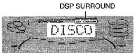
"DSP SURROUND" appears and the DSP SURROUND mode is displayed cyclically as follows.

flowchart
graph LR
    A["DISCO"] <--> B["LIVE"]
    B <--> C["MOVIE"]
    C <--> D["HALL"]
    E["DSP OFF (cancel)"] <--> F["M4"]
    F <--> G["M3"]
    G <--> H["M2"]
    H <--> I["M1"]
    I <--> J["Manual mode"]
    style A fill:#f9f,stroke:#333
    style B fill:#f9f,stroke:#333
    style C fill:#f9f,stroke:#333
    style D fill:#f9f,stroke:#333
    style E fill:#f9f,stroke:#333
    style F fill:#f9f,stroke:#333
    style G fill:#f9f,stroke:#333
    style H fill:#f9f,stroke:#333
    style I fill:#f9f,stroke:#333
    style J fill:#f9f,stroke:#333
Equalization curves are selected automatically to match the DSP SURROUND modes and can also be selected or turned off to suit your preference.
To display the current DSP SURROUND mode
Press SURROUND. The current mode is displayed for 4 seconds.
To cancel the selected mode
Press SURROUND, and turn MULTI JOG to select "DSP OFF" within 4 seconds. "DSP SURROUND" disappears.
When the music source is monaural
Select "LIVE" or "MOVIE" to obtain a simulated stereo effect. When "DISCO" or "HALL" is selected, no sound will be heard from the surround speakers.
The elements of the DSP SURROUND sound can be customized.

DELAY (delay time)
Increasing the number in the display increases the delay time and surround effect. "15", "20", "30" or "50" mSec can be selected.
To adjust the delay time
Press DELAY, and turn MULTI JOG to select one of the levels within 4 seconds.

L-R, L+R (input mode)
When "L+R" is displayed, the surround effect increases, especially in the center.
When "L-R" is displayed, it increases on the outside.
To select a input mode
Press EFFECT once, and turn MULTI JOG to select "L-R" or "L+R" within 4 seconds.

FB (feedback level)
Increasing the number in the display increases the echo.
A level from "OFF" (0) to "7" can be selected.
To adjust the level of feedback
Press EFFECT twice, and turn MULTI JOG to select one of the levels within 4 seconds.

Up to 4 DSP SURROUND sound can be memorized as the manual modes M1 - M4.

1 Set a new DSP SURROUND sound with DELAY, EFFECT, and MULTI JOG.
See "SETTING A NEW DSP SURROUND SOUND MANUALLY".
2 Within 4 seconds, press ENTER.
"M1" flashes on the display.

- If this step is not completed within 4 seconds, press SURROUND first to display "DSP ON". Then press ENTER within 4 seconds.
3 Within 4 seconds, turn MULTI JOG to select one of the manual modes M1 - M4.
4 Within 4 seconds, press ENTER.
The new DSP SURROUND sound is memorized.
To select the stored DSP SURROUND sound
Press SURROUND, and turn MULTI JOG to select one of the manual modes M1 - M4 within 4 seconds.
To adjust the volume of the surround speakers
Press MANUAL SELECT twice or three times on the remote control.
"S-L" or "S-R" is displayed for 2 seconds. Press I◄◄ DOWN or ►►I UP on the remote control within these 2 seconds.
- The DOLBY PRO LOGIC (page 21) and the DOLBY DIGITAL SURROUND (page 28) surround speakers level is also changed.
NOTE
The SURROUND mode is canceled when:
- the ECHO level is changed.
- the DOLBY PRO LOGIC is turned on.
- the headphones are plugged in.
- the 5.1 CH (page 28) is selected.
MANUAL TUNING
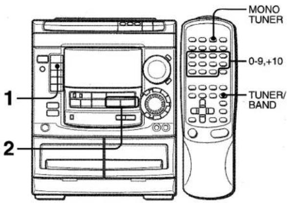
1 Press TUNER BAND repeatedly to select the desired band.
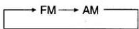
When TUNER BAND is pressed while the power is off, the power is turned on directly.
2 Press ◀◀ DOWN or ▶▶ UP to select a station.
Each time the button is pressed, the frequency changes. When a station is received, "TUNE" is displayed for 2 seconds. During FM stereo reception, (100) is displayed.

To search for a station quickly (Auto Search)
Keep ◀◀ DOWN or ▶▶ UP pressed until the frequency starts to change rapidly. After tuning in to a station, the search stops. To stop the Auto Search manually, press ◀◀ DOWN or ▶▶ UP.
• The Auto Search may not stop at stations with very weak signals.
When an FM TUNER stereo broadcast contains noise
Press MONO TUNER on the remote control so that "MONO" appears on the display.
Noise is reduced, although reception is monaural.

To restore stereo reception, press MONO TUNER so that "MONO" disappears.
PRESETTING STATIONS

The unit can store a total of 32 preset stations. When a station is stored, a preset number is assigned to the station. Use the preset number to tune in to a preset station directly.
1 Press TUNER BAND to select a band, and press ◀◀ DOWN or ▶▶ UP to select a station.
2 Press II SET to store the station.
A preset number beginning from 1 in consecutive order for each band is assigned to the station.
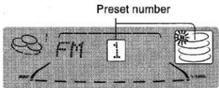
3 Repeat steps 1 and 2.
The next station will not be stored if a total of 32 preset stations for all the bands have already been stored.
PRESET NUMBER TUNING
Use the remote control to select the preset number directly.
1 Press BAND to select a band.
2 Press numbered buttons 0-9 and +10 to select a preset number.
Example:
To select preset number 20, press +10, +10 and 0.
To select preset number 15, press +10 and 5.
Selecting a preset number on the main unit
Press TUNER BAND to select a band. Then, press ◀▶ PRESET repeatedly or turn MULTI JOG.
Each time ◀▶ PRESET is pressed, the next ascending number is selected.
To clear a preset station
Select the preset number of the station to be cleared. Then, press ■ CLEAR, and press II SET within 4 seconds.
The preset numbers of all other stations in the band with higher numbers are also decreased by one.
To change the AM tuning interval
The default setting of the AM tuning interval is 10 kHz/step. If you use this unit in an area where the frequency allocation system is 9 kHz/step, change the tuning interval.
Press POWER while pressing TUNER BAND.
To reset the interval, repeat this procedure.
NOTE
When the AM tuning interval is changed, all preset stations are cleared. The preset stations have to be set again.
BASIC OPERATIONS

Use Type I (normal) tapes only.
1 Press TAPE and press ▲ EJECT to open the cassette holder.

Insert a tape with the exposed side down. Push the cassette holder to close.
2 Press ◀▶ to start play.
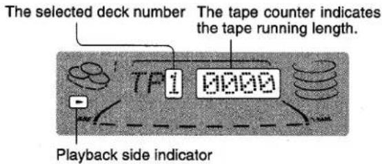
▶: The front side is being played (forward).
◀: The back side is being played (reverse).
To select a playing deck
When tapes are loaded in both decks, press TAPE first to select a deck.
The selected deck number is displayed.
To stop play, press ■.
To pause play (deck 2 only), press III. To resume play, press again.
To change the playback side (deck 1 only), press ◀▶ in play or pause mode.
To fast forward or rewind, press ◀◀ or ▶▶. Then press ■ to stop the tape.
To start play when the power is off (Direct Play Function)
Press TAPE. The power is turned on and play of the inserted tape begins.
To set the tape counter to 0000
Press ■ CLEAR in stop mode.
The counter is also set to 0000 when the cassette holder is opened.
When tapes are loaded in both decks
After playback of both sides (front and back) on deck 1 finishes, the tape in deck 2 will start to play without interruption and will stop at the end of the front side of the tape. (Continuous play)
MUSIC SENSOR (deck 1 only)
If there is a 4-second or longer blank between each track, a search for the beginning of the current or next track during playback can be done easily.
Press ◀◀ or ▶▶ during playback referring to the playback side indicator (◀ or ▶) on the display.
For example, when ▶▶ is pressed while ▶ is displayed, playback of the next track starts after searching.
Music sensor function may not be able to detect tracks under the following conditions:
- Blanks of less than 4 seconds between tracks
- Noisy blanks
- Long passages of low-end sound
- Low overall recording levels
About cassette tapes
- To prevent accidental erasure, break off the plastic tabs on the cassette tape after recording with a screwdriver or other pointed tool.

To record on the tape again, cover the tab openings with adhesive tape, etc.
- 120-minute or longer tapes are extremely thin and easily deformed or damaged. They are not recommended.
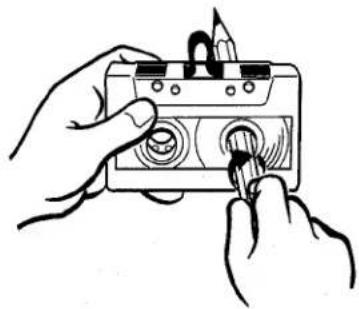
• Take up any slack in the tape with a pencil or similar tool before use. Slack tape may break or jam in the mechanism.
natural_image
Illustration of hands using a handheld device to adjust a component (no text or symbols visible)BASIC OPERATIONS

LOADING DISCS
Press CD, then press ▲ OPEN/CLOSE to open the disc compartment. Load disc(s) with the label side up.
To play one or two discs, place the discs on tray 1 and 2. To play three discs, press DISC CHANGE to rotate the trays after placing two discs. Place the third disc on tray 3. Close the disc compartment by pressing ▲ OPEN/CLOSE.


PLAYING DISCS
Load discs.
To play all discs in the disc compartment, press ◀▶. Play begins with the disc on tray 1.
Number of track being played Elapsed playing time

To play one disc only, press DISC DIRECT PLAY 1-3. The selected disc is played once.
To play with the remote control
Press DISC DIRECT PLAY, then press numbered buttons 1-3 within 3 seconds to select a disc.
To stop play, press ■.
To pause play, press III. To resume play, press again. To search for a particular point during playback, keep ◀◀◀ or ▶▶ pressed and release it at the desired point.
To skip to the beginning of a track during playback, press ◀◀ or ▶▶ repeatedly or turn MULTI JOG.
To remove discs, press ▲ OPEN/CLOSE.
To start play when the power is off (Direct Play Function) Press CD. The power is turned on and play of the loaded disc(s) begins.
When ▲ OPEN/CLOSE is pressed, the power is also turned on and the disc compartment is opened.
To check the remaining time
During play, press CD EDIT/CHECK. The amount of time remaining until all tracks finish playing is displayed. To restore the playing time display, repeat the above.
Selecting a track with the remote control
1 Press DISC DIRECT PLAY, then press numbered buttons 1-3 within 3 seconds to select a disc.
2 Press numbered buttons 0-9 and +10 to select a track. Example:
To select the 25th track, press +10, +10 and 5.
To select the 10th track, press +10 and 0.
The selected track starts to play and continues to the end of that disc.
Replacing discs during play
While one disc is playing, the other discs can be replaced without interrupting play.
1 Press DISC CHANGE.
2 Remove the discs and replace with other discs.
3 Press ▲ OPEN/CLOSE to close the disc compartment.
NOTE
- When loading an 8-cm (3-inch) disc, put it onto the inner circle of the tray.
- Do not place more than one compact disc on one disc tray.
- Do not tilt the unit with discs loaded. Doing so may cause malfunctions.
- Do not use irregular shape CDs (example: heart-shaped, octagonal ones). It may result in malfunctions.
RANDOM /REPEAT PLAY
Use the remote control.
RANDOM play
All the tracks on the selected disc or all the discs can be played randomly.
REPEAT play
A single disc or all the discs can be played repeatedly.
Press RANDOM/REPEAT.
Each time it is pressed, the function can be selected cyclically.
RANDOM play — RANDOM lights up on the display.
REPEAT play — lights up on the display.
RANDOM/REPEAT play — RANDOM and ➕ light up on the display.
Cancel — RANDOM and ↩ disappear from the display.
To play all discs, press ◀▶ to start play.
To play a single disc, press one of DISC DIRECT PLAY 1-3 to start play.
NOTE
During random play it is not possible to skip to the previously played track with ◀◀.
PROGRAMMED PLAY
Up to 30 tracks can be programmed from any of the inserted discs.

Use the remote control.
1 Press PRGM twice in stop mode.
"PRGM" is displayed.

- When the PRGM is pressed once in step 1, the unit enters the KARAOKE PROGRAM (page 24).
2 Press DISC DIRECT PLAY, then press numbered buttons 1-3 within 3 seconds to select a disc.
Go to the next step when the tray stops rotating.
3 Press numbered buttons 0-9 and +10 to program a track.
Example:
To select the 25th track, press +10, +10 and 5.
To select the 10th track, press +10 and 0.

4 Repeat steps 2 and 3 to program other tracks.
5 Press ◀▶ to start play.
To check the program
Each time ◀◀ or ▶▶ is pressed in stop mode, a disc number, track number, and program number will be displayed.
To clear the program
Press ■ CLEAR in stop mode.
To add tracks to the program
Repeat steps 2 and 3 in stop mode. The track will be programmed after the last track.
To change the programmed tracks
Clear the program and repeat all the steps again.
To play the programmed tracks repeatedly
After programming the tracks, press RANDOM/REPEAT repeatedly until appears on the display.
NOTE
During programmed play, you cannot perform random play, checking the remaining time, or selecting a disc or track.
BASIC RECORDING
This section explains how to record from the tuner, CD player, or external equipment.

Preparation
• Use Type I (normal) tapes only.
- Set the tape to the point where recording will start.
- Note that recording is done on only one side of the tape.
1 Insert the tape to be recorded on into deck 2.
Insert the tape with the side to be recorded on first facing out from the unit.

2 Press function (CD, TUNER, VIDEO/AUX or MD) and prepare the source to be recorded.
To record from a CD, press CD and load the disc(s). To record from a radio broadcast, press TUNER and tune in to a station. To record from a connected source, press VIDEO/AUX or MD.
3 Press ● REC/REC MUTE to start recording.
When the selected function is CD, playback and recording start simultaneously.

When recording from a connected source, start playback of the source.
To stop recording, press ■.
To pause recording, press III. (Applicable when the source is TUNER, VIDEO/AUX or MD) To resume recording, press it again.
To start recording with the remote control
First press ●/○ REC/REC MUTE, and then press ◀▶ within 2 seconds.
Sound adjustment during recording
The output volume and tone (except BBE) of the speakers or headphones may be freely varied without affecting the recording.
INSERTING BLANK SPACES
Insertion of 4-second blank spaces enables you to activate the Music Sensor function. (Applicable when the source is TUNER, VIDEO/AUX or MD.)
1 Press ● REC/REC MUTE during recording or while in recording pause mode.
REC on the display flashes for 4 seconds and the tape runs without recording. After 4 seconds, the deck enters the recording pause mode.
2 Press II to resume recording.
To insert a blank space of less than 4 seconds, press REC/REC MUTE again while REC is flashing.
To insert blank spaces of more than 4 seconds, after the deck enters recording pause mode, press ● REC/REC MUTE again. Each time the button is pressed, a 4-second blank space is added.
To erase a recording
Make sure the microphone is not connected to this unit.
Set the microphone volume and the echo level to OFF (See page 23).
1 Insert the tape to be erased into deck 2 and press TAPE DECK 1/2 to display "TP 2".
2 Set the tape to the point where the erasure is to be started.
3 Press ● REC/REC MUTE to start the erasure.
DUBBING A TAPE MANUALLY

NOTE
- Set the tape to the point where recording will start.
- Note that recording will be done on one side of the tape only.
1 Press TAPE.
2 Insert the original tape into deck 1 and the tape to be recorded on into deck 2.
Insert the tapes with the sides to be played back or recorded on facing out from the unit.
3 Press TAPE DECK 1/2 to select deck 1.
"TP 1" is displayed.
4 Press ● REC/REC MUTE to start recording.
Playing and recording start simultaneously.
To stop dubbing
Press ■.
DUBBING THE WHOLE TAPE

This function allows you to make exact copies of the original tape.
NOTE
- Dubbing does not start from a point halfway in the tape.
- Note that recording will be done on one side of the tape only.
1 Press TAPE.
2 Insert the original tape into deck 1 and the tape to be recorded on into deck 2.
Insert each tape with the side to be played back or recorded on facing out from the unit.
3 Press SYNCHRO DUBBING to start recording.

The tapes are rewound to the beginning of the front sides, and recording starts.
To stop dubbing
Press ■.
AI EDIT RECORDING
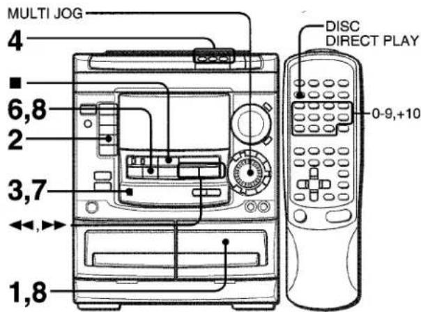
The AI edit recording function enables CD recording without worrying about tape length and track length. When a CD is inserted, the unit automatically calculates the total track length. If necessary, the order of tracks is rearranged so that no track is cut short.
(AI: Artificial Intelligence)
NOTE
AI edit recording will not start from a point halfway into the tape.
The tape must be recorded from the beginning of either side.
1 Insert the tape into deck 2.
Insert the tape with the side to be recorded on first facing out from the unit.
2 Press CD and load the disc(s).
3 Press CD EDIT/CHECK once.
"EDIT" is displayed.

- When "PRGM" is displayed, press CD EDIT/CHECK again.
4 Press DISC DIRECT PLAY 1-3 to select a disc.
5 Press numbered buttons 0-9 on the remote control to designate the tape length.
10 to 99 minutes can be specified.
Example: When using a 60-minute tape, press 6 and 0. In a few seconds, the tracks to be recorded on each side of the tape are determined.
- ◀◀, ▶▶ or MULTI JOG are also available to designate the tape length.
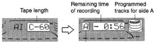
Tape side
A: First recording side
B: Second recording side
6 Press ● REC/REC MUTE to start recording on the first side.
The tape is rewound to the beginning of the first side, the lead segment is played through for 10 seconds, and recording starts. When the last track programmed for side A is finished, deck 2 enters the recording stop mode. After entering the recording stop mode, go to step 7.
7 Press CD EDIT/CHECK to display the program for the second recording.
"B" is displayed.
8 Turn over the tape in deck 2 and press ● REC/REC MUTE to start recording on the second side.
To stop recording
Press ■ CLEAR. Recording and CD play stop simultaneously.
To clear the edit program
Press ■ CLEAR twice so that "EDIT" disappears on the display.
To check the order of the programmed track numbers
Before recording, press CD EDIT/CHECK to select side A or B, and press ◀◀ or ▶▶ repeatedly.

Program number
To add tracks from other discs to the edit program
If there is any time remaining on the tape after step 5, you can add tracks from other discs in the CD compartment.
1 Press CD EDIT/CHECK to select side A or B.
2 Press DISC DIRECT PLAY 1-3 to select a disc.
3 Press numbered buttons on the remote control to select tracks. A track whose playing time is longer than the remaining time cannot be programmed.
4 Repeat steps 2 and 3 to add more tracks.
Time on cassette tapes and editing time
The actual cassette recording time is usually a little longer than the specified recording time printed on the label. This unit can program tracks to use the extra time. When the total recording time is a little longer than the tape's specified recording time after editing, the display shows the extra time (without a minus mark), instead of the time remaining on the tape (with the minus mark).
NOTE
- The AI edit recording function cannot be used with discs containing 31 tracks or more.
PROGRAMMED EDIT RECORDING

In the programmed edit recording function the tracks can be programmed while checking the remaining time on each side of the tape as the tracks are programmed.
NOTE
The programmed edit recording will not start from a point halfway in the tape. The tape must be recorded on from the beginning of either side.
1 Insert the tape into deck 2.
Insert the tape with the side to be recorded on first facing out from the unit.
2 Press CD and load the disc(s).
3 Press CD EDIT/CHECK twice.
"EDIT" and "PRGM" are displayed.
- When "AI" is displayed, press CD EDIT/CHECK again.
4 Press numbered buttons on the remote control to designate the tape length.
10 to 99 minutes can be specified.
- The ◀◀, ▶▶ or MULTI JOG are also available to designate the tape length.

5 Press DISC DIRECT PLAY 1-3 to select a disc.
Then, press numbered buttons 0-9 and +10 on the remote control to program a track.
Example: To select the 10th track of disc 2, press DISC DIRECT PLAY 2, then press +10 and 0.

6 Repeat step 5 for the rest of the tracks for side A.
A track whose playing time is longer than the remaining time cannot be programmed.
7 Press CD EDIT/CHECK to select side B and program the tracks for side B.
After confirming "B" on the display, repeat step 5.
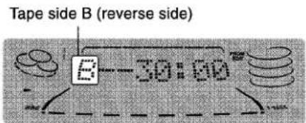
8 Press CD EDIT/CHECK to select side A and press ● REC/REC MUTE to start recording.
CD play and recording of edited tracks for the first side start simultaneously. When the last track programmed for side A is finished, deck 2 enters the recording stop mode. After entering the recording stop mode, go to step 9.
9 Press CD EDIT/CHECK for recording of the second side.
"B" is displayed.
10 Turn over the tape in deck 2 and press ● REC/REC MUTE to start recording.
Recording starts.
To stop recording
Press ■. Recording and CD play stop simultaneously.
To check the order of the programmed track numbers
Before recording, press CD EDIT/CHECK to select side A or B, and press ◀◀ or ▶▶ repeatedly.

To change the program of each side
Press CD EDIT/CHECK to select side A or B, and press ■ CLEAR to clear the program on the selected side. Then program tracks again.
To clear the edit program
Press ■ CLEAR twice so that "EDIT" disappears on the display.
NOTE
- Up to 30 tracks can be programmed from any of the inserted discs.
DOLBY PRO LOGIC
The DOLBY PRO LOGIC feature and the center and rear speakers (standard) assure full-scale home theater sound. When playing back laser discs or video software that have been recorded in Dolby Surround, astonishingly realistic sound surrounds the listener to create a new level of audio/visual entertainment.
Independent control of the four sound channels allows the listener to enjoy the same type of sound reproduction experienced in movie theaters. Voices are reproduced in the front and center sound field, while ambient sounds like cars and crowds are reproduced on all sides of the listener for an incredibly lifelike audio/video experience. Please read the following carefully to "tune" the system's output to match the characteristics of your listening space.
Check the following:
- Before using the DOLBY PRO LOGIC, adjust the proper balance of speaker sound levels.
- Make sure the supplied speakers are properly connected and positioned. (See page 3 and 4)
- Make sure the TV set and video unit are properly connected. (See page 4)
• Make sure the laser disc, video tape, etc., support DOBY SURROUND.
The unit is equipped with a built-in test signal generator called a noise sequencer for easy balance adjustment of all 5 channels. The sequencer outputs a noise signal that "travels" from channel to channel, enabling the simple adjustment of sound level to achieve, at the listening position, the same apparent loudness from each channel.
Use the remote control.
1 Press DOLBY PRO LOGIC to select "NORMAL".
"NORMAL" lights up in red.
If "PHANTOM" or "3 STEREO" lights up in red, press DOLBY PRO LOGIC repeatedly until "NORMAL" is selected.
2 Press MANUAL SELECT (TEST) and hold it down for about 4 seconds until "L" flashes.

A noise signal is sent to each channel in turn in the following sequence.
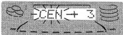
→L: Left speaker → CEN: Center speaker → R: Right speaker S-L: Left surround speaker ← S-R: Right surround speaker
3 Adjust the sound level of the center and the surround speakers.
While "CEN" "S-R" or "S-L" is displayed, press ◀◀ DOWN or ▶▶ UP to adjust the volume of the center or each surround speaker to match the level of the front speakers.
To adjust the balance between the left and right front speakers, see page 7. At this time, the DOLBY PRO LOGIC mode should be canceled by pressing DOLBY PRO LOGIC until the "P-OFF" is displayed.
4 Press MANUAL SELECT (TEST) again to stop the noise signal.
NOTE
- If the surround speakers or the center speaker level of the DOLBY PRO LOGIC is changed, that of the SURROUND system (page 11) and the DOLBY DIGITAL SURROUND (page 28) is also changed.
- While "S-L" or "S-R" is displayed, both surround speakers output the noise signal together. However, only the sound level of one surround speaker displayed as "S-L" or "S-R" can be adjusted.
- When the sequencer outputs a noise signal, a clicking sound might be heard from the speakers due to the characteristics of the circuit. This is not malfunction.
About the channels
The left and right front speakers create the stereo effect.
The center speaker helps achieve precise sound positioning over a broad sound field.
The rear-mounted surround speakers enhance the "depth" of the sound field.
To change the delay time
The surround speakers reproduce sounds a split second after the front speakers. The delay is initially set to 20 ms (milliseconds).
To change this standard delay time, press MANUAL SELECT (TEST) on the remote control repeatedly until "TIME" is displayed. Then, press ◀◀ DOWN or ▶▶ UP. Each time one of the buttons is pressed, the delay time changes as shown below.

PLAY WITH DOLBY PRO LOGIC

1 Press VIDEO/AUX/5.1 CH and start playback of the video source.
"VIDEO" is displayed.
If "5.1 ch IN" is displayed, press VIDEO/AUX/5.1 CH again.
“NORMAL” is selected, and the playback sound has the DOLBY PRO LOGIC effect.
To cancel Dolby Pro Logic mode
Press DOLBY PRO LOGIC repeatedly until "P-OFF" is displayed.
To change the sound levels during playback
After adjusting the balance with the noise sequencer, the sound levels of the center or each surround speaker can be adjusted during playback of laser discs or video software.
1 Press MANUAL SELECT (TEST) on the remote control repeatedly to select "CEN" (center speaker) "S-L" (Left surround speaker) or "S-R" (Right surround speaker).
2 While the "CEN" "S-L" or "S-R" is displayed, press ◀ DOWN or ▶ UP on the remote control to adjust the volume.
ADDITIONAL DOLBY PRO LOGIC MODES
In addition to the NORMAL mode, this unit is also equipped with the PHANTOM and the 3 STEREO modes.
PHANTOM mode: Use this mode when no center speaker is connected. The center channel signals are output through the left and right speakers.
3 STEREO mode: Use this mode when no surround speakers are connected. This mode reproduces rear sounds through the front speakers.
To select PHANTOM or 3 STEREO
Press DOLBY PRO LOGIC repeatedly until the desired DOLBY PRO LOGIC mode is displayed. The DOLBY PRO LOGIC mode is displayed cyclically as follows.

To adjust the balance of connected speaker sound levels Carry out steps 2 to 4 of "ADJUSTING SPEAKER LEVEL BALANCE".
NOTE
- Depending on the sound source and/or listening conditions, a surround effect may not be obtained even when the DOLBY PRO LOGIC is on.
- The full DOLBY PRO LOGIC effect cannot be obtained when using software without ☐DOLBY SURROUND mark. In this case, use the SURROUND system instead. (See page 10.)
• The DOLBY PRO LOGIC is automatically canceled when:
- the ECHO level is changed.
- the SURROUND system or the BBE is turned on.
- the headphones are plugged in.
- the Karaoke function is turned on.
- the 5.1 CH (page 28) is selected.
- Set the microphone volume to OFF while the DOLBY PRO LOGIC is on. Otherwise, the DOLBY PRO LOGIC sound cannot be reproduced correctly.
MICROPHONE MIXING

Two microphones (not supplied) can be connected to this unit, allowing you to sing along to music sources. Use microphones with mini plugs (ø3.5 mm, 18 inch).
1 Connect your microphones to MIC 1 and MIC 2 jacks.

2 Press one of the function buttons to select the source to be mixed, and play the source.
3 Adjust the volume and tone of the source.
4 Press MIC and turn VOLUME within 4 seconds to adjust the microphone volume.
The microphone volume can be selected from 1 to MAX (7) or OFF (cancel).
The volume of both microphones is adjusted simultaneously.
5 Press ECHO and turn VOLUME within 4 seconds to adjust the echo level.
The echo level can be selected from 1 to MAX (7) or OFF (cancel).
To change the delay time of echo
Hold down ECHO while the echo is on.
"L" (Long) and "M" (Middle) are displayed alternately. At the desired position, release the button.
To record microphone sound mixed with source sound Follow the procedure for recording from the sound source (See page 17).
SYNCHRO DUBBING cannot be used for mixing recording.
When not using the microphones
Set the microphone volume and echo level to OFF and remove the microphones from MIC jacks.
NOTE
- When the ECHO level is changed, the SURROUND system and the DOLBY PRO LOGIC are automatically canceled.
- When the MIC or ECHO is turned on while the 5.1 CH (page 28) is selected, the 5.1 CH is chaged to VIDEO.
-
If a microphone is held too near the speakers, a howling sound may be produced. In this case, hold the microphone away from the speakers, or decrease the microphone volume.
-
If sound through the microphone is extremely loud, it may be distorted. In this case, decrease the microphone volume.
- When the function is changed, the microphone volume and the echo volume are set to off.
Recommended microphones
The use of unidirectional type microphones is recommended to prevent howling. Contact your local Aiwa dealer for details.
VOCAL FADER/MULTIPLEX FUNCTIONS
This unit can use discs or tapes as Karaoke sources. Use the vocal fader function for ordinary discs or tapes. Use the multiplex function for multi audio discs or tapes.
Press KARAOKE repeatedly to select the vocal fader or multiplex function.
Each time KARAOKE is pressed, one of these functions is selected cyclically.

flowchart
graph TD
    A["① UF"] --> B["② A-UF"]
    B --> C["③ MPX-L"]
    C --> D["④ A-MPX"]
    D --> E["⑤ VF OFF"]
    E --> A
① Vocal Fader
The singer's voice becomes softer than the accompaniment.
② Auto Vocal Fader
The singer's voice becomes softer only while there is audio input through a microphone.
③ Multiplex
Only the sound on the left channel is heard from both speakers, and the sound on the right channel is muted.
④ Auto Multiplex
The sound on the left channel is heard from both speakers, and the sound on the right channel is muted only while there is audio input through a microphone.
⑤ Cancel
To change the time lag setting in Auto Vocal Fader or Auto Multiplex function
The muted original singer's voice can be turned faster than the normal level.
When Auto Vocal Fader or Auto Multiplex is selected, "A-VF" or "A-MPX" is displayed for 3 seconds and changes to the selected function name. After the selected function name is displayed, keep pressing KARAOKE until "FAST" is displayed.
To return to the initial setting, select SLOW.
When the power is turned off, SLOW is restored.
To change the audible channel in Multiplex function
When Multiplex is selected, "MPX -L" is displayed for 3 seconds and changes to the selected function name. After the selected function name is displayed, keep pressing KARAOKE until "MPX-R" is displayed.
To return to the initial setting, select MPX-L.
When the power is turned off, MPX-L is restored.
NOTE
- The Karaoke functions may not operate correctly with the following kinds of CDs or tapes.
- Those with monaural sound
- Those recorded with strong echoes
- Those with the vocal part recorded on the right or left side of the sound width
- While the Karaoke function is on, the sound is output as monaural.
- When the function is changed, the Karaoke function is canceled.
KARAOKE PROGRAM
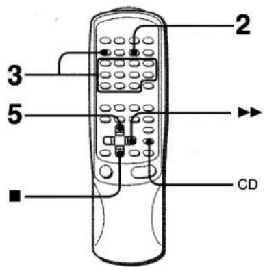
Before or during CD play, you can reserve up to 15 tracks to be played after the current track. Each reservation is cleared when it finishes playing.
Use the remote control.
1 Press CD and load the discs.
2 Press PRGM once.
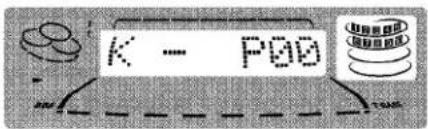
3 Press DISC DIRECT PLAY, then press numbered buttons 1-3 within 3 seconds to select a disc. Then, press numbered buttons 0-9 and +10 to program a track.
Reserved disc number Reserved track number

4 Repeat step 3 to reserve other tracks.
5 Press ◀▶ to start play.
After a track is played, it is cleared from the program.

To add a reservation during play
Repeat step 3.
To check the reserved tracks
Press CD EDIT/CHECK repeatedly. Each time it is pressed, the disc number and track number are displayed in the reserved order.
To stop play
Press ■
When ◀▶ is pressed, the play starts from the last track again.
To skip a current track
Press ▶▶. The skipped track is cleared from the program.
To clear all the reservations
Press ▶▶ repeatedly until "K - P00" is displayed.

Press it once more to cancel the Karaoke programs. The display returns to that of CD play.
NOTE
- If the reserved track number does not exist on the selected disc, the unit stops playing and the display flashes. In this case, press ▶▶ to skip the error track. Then press ◀▶ to start play with the next reserved track.
- When PRGM is pressed repeatedly in step 1, PRGM is displayed and the unit enters CD program play mode (page 16).
To cancel program play, press ■ CLEAR.
En
SETTING THE CLOCK

1 Press CLOCK, then press II SET within 4 seconds.
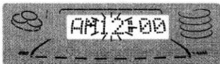
2 Press ◀◀ DOWN or ▶▶ UP to designate the hour, then press || SET.
The hour stops flashing and the minute starts flashing.
3 Press ◀◀ DOWN or ▶▶ UP to designate the minute, then press II SET.
The minute stops flashing on the display and the clock starts from 00 seconds.
To display the current time
Press CLOCK. The time is displayed for 4 seconds.
However, the time cannot be displayed during recording.
To switch to the 24-hour standard
Press the CLOCK and then press ■ within 4 seconds.
Repeat the same procedure to restore the 12-hour standard.
If the clock display flashes
This is caused by a power interruption. The current time needs to be reset.
If power is interrupted for more than approximately 24 hours, all settings stored in memory after purchase need to be reset.
* MULTI JOG is also available instead of ◀◀ and ▶▶.
* ENTER is also available instead of II SET.
SETTING THE SLEEP TIMER

The unit can be turned off automatically at a specified time.
Use the remote control.
1 Press SLEEP.
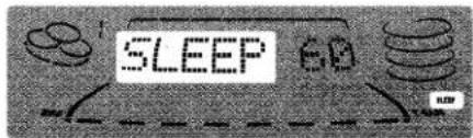
2 Within 4 seconds, press ◀◀ or ▶▶ to specify the time until the power is turned off.
Each time the button is pressed, the time changes between 5 and 240 minutes in 5-minute steps.

To check the time remaining until the power is turned off Press SLEEP once. The remaining time is displayed for 4 seconds.
To cancel the sleep timer
Press SLEEP twice so that "SLEEP OFF" appears on the display.
* MULTI JOG is also available instead of ◀◀ and ▶▶.
SETTING THE TIMER

The unit can be turned on at a specified time every day with the built-in timer.
Preparation
Make sure the clock is set correctly.
1 Press TIMER repeatedly to display Ⓕ, then press || SET within 6 seconds.
② is displayed and the hour flashes.

NOTE
If you press II SET after 6 seconds, another operation may start.
2 Designate the hour of the timer-on time by pressing ◀◀ DOWN or ▶▶ UP, then press II SET.
Repeat to designate the minute of the timer-on time.

After you designate the timer-on time, one of the source names flashes on the display.
3 Press ◀◀ DOWN or ▶▶ UP to select a source, then press || SET.
- If TUNER is selected, the band cannot be selected in this step.

4 Select the duration for the timer-activated period with ◀◀ DOWN or ▶▶ UP, then press || SET.
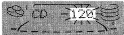
The duration for the timer-activated period can be set between 5 and 240 minutes in 5-minute steps.
5 Prepare the source.
To listen to a CD, load the CD to be played first on tray 1. To listen to a tape, insert the tape into deck 1 or 2. To listen to the radio, tune in to a station.
6 Press POWER to turn the unit off after adjusting the volume and tone.
② remains on the display after the power is turned off (timer standby mode).

When the timer-on time is reached, the unit turns on and begins play with the selected source.
The volume level is automatically set to 20 when the power is turned off with the volume level set to 21 or more.
To check the specified time and source
Press TIMER twice. The timer-on time, the selected source name and the duration for the timer-activated period are displayed for 4 seconds.
To cancel timer standby mode temporarily
Press TIMER repeatedly until Ⓑ or ⒹREC disappears on the display.
To restore the timer standby mode, press TIMER repeatedly to display ⊕ or ⊕REC.
Using the unit while the timer is set
You can use the unit normally after setting the timer. Before turning off the power, carry out step 5 to prepare the source, and adjust the volume and tone.
NOTE
- Timer playback and timer recording will not begin unless the power is turned off.
- Connected equipment cannot be turned on and off by the built-in timer of this unit. Use an external timer.
* MULTI JOG is also available instead of ◀◀ and ▶▶.
* ENTER is also available instead of II SET.
TIMER RECORDING
Timer recording is applicable for TUNER and VIDEO/AUX (with an external timer) sources only.
Press TIMER repeatedly until Ⓐ REC appears on the display, then press || SET within 6 seconds. Carry out the steps of "SETTING THE TIMER" from step 2 and insert the tape to be recorded on into deck 2 after step 5.
CONNECTING OPTIONAL EQUIPMENT

Refer to the operating instructions of the connected equipment for details.
- The connecting cords are not supplied. Obtain the necessary connecting cords.
- Consult your local Aiwa dealer for optional equipment.
VIDEO/AUX JACKS
This unit can input analog sound signals through these jacks. Use a cable with RCA phono plugs to connect audio equipment (DVD player, turntables, LD players, MD players, VCRs, TV, etc.). Connect the red plug to VIDEO/AUX R jack, and the white plug to VIDEO/AUX L jack.
When connecting a turntable
Use an Aiwa turntable equipped with a built-in equalizer amplifier.
MD JACKS
This jack is recommended to connect with an MD player.
Use a cable with RCA phono plugs.
Connect the red plug to MD R jack, and the white plug to MD L jack.
LINE OUT JACKS
This unit can output analog sound signal through these jacks.
Use a cable with RCA phono plugs to connect audio equipment with LINE IN (analog input) jacks.
Connect the red plug of a cable to LINE OUT R jack, and the white plug to LINE OUT L jack.
NOTE
Do not connect an equipment to LINE OUT jacks and VIDEO/AUX jacks simultaneously. Otherwise, noise is generated and malfunction occurs.
CD DIGITAL OUT (OPTICAL) JACK
This unit can output CD digital sound signals through this jack. Use an optical cable to connect digital audio equipment (DAT deck, MD recorder, etc.).
Remove the dust cap ⓐ from CD DIGITAL OUT (OPTICAL) jack. Then, connect an optical cable plug to CD DIGITAL OUT (OPTICAL) jack.

flowchart
graph LR
    A["(OPTICAL) CD DIGITAL OUT"] --> B["Input"]
    B --> C["(OPTICAL) CD DIGITAL OUT"]
    C --> D["Output"]
When CD DIGITAL OUT (OPTICAL) jack is not being used Attach the supplied dust cap.
SUB WOOFER JACK 📁 JACK
Connect an optional powered sub woofer with built-in-amplifier to the jack.
5.1 CH INPUT JACKS
This unit can input sound signals from the audio equipment (DVD player, LD player, etc.) that contains a Dolby Digital decoder with the 5.1 ch output terminals. Refer to "CONNECTING A DVD PLAYER" on page 28.
LISTENING TO EXTERNAL SOURCES

To play a equipment connected to VIDEO/AUX jacks or MD jacks proceed as follows.
1 Press VIDEO/AUX/5.1 CH or MD.
To play the equipment connected to VIDEO/AUX, press VIDEO/AUX/5.1 CH. "VIDEO" appears on the display.
To play the equipment connected to MD, press MD. "MD" appears on the display.
2 Play the connected equipment.
To change a source name in the display
When VIDEO/AUX/5.1 CH is pressed, "VIDEO" is displayed initially. It can be changed to "AUX" or "TV".
With the power on, press POWER while pressing VIDEO/AUX/5.1 CH.
Repeat the procedure to select one of the names.
To adjust the sound level of the external source
When the sound level of the external source is much higher or much lower than that of other function sources, adjust it as follows.
1 Press VIDEO/AUX/5.1 CH or MD and play the equipment.
2 Press ◀◀ or ▶▶ so that the sound level becomes the same as that of other function sources.
NOTE
During recording, the sound level can not be adjusted.
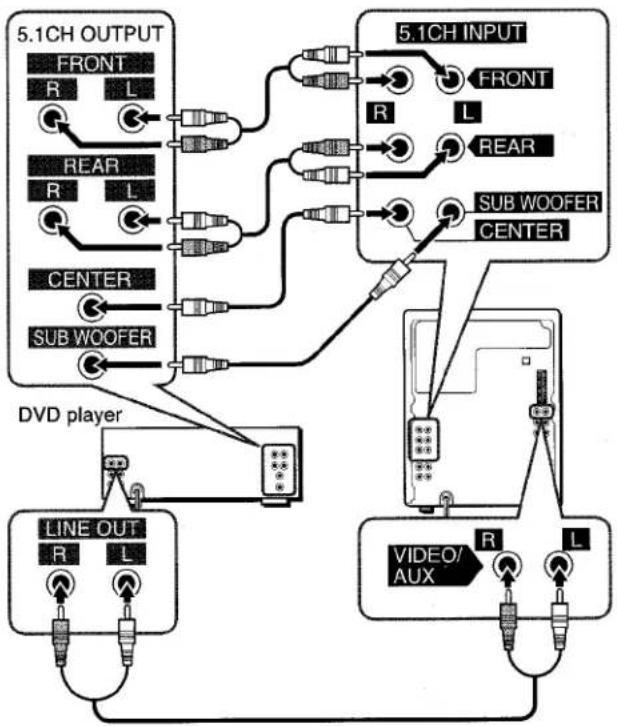
CONNECTING A DVD PLAYER
5.1CH INPUT jacks of this unit support the DOLBY DIGITAL SURROUND system.
Connect a DVD player with 5.1CH output jacks to this unit using cables with RCA phono plugs as follows;
| DVD player's jack | This unit's jack |
| 5.1CH OUTPUT FRONT (L,R), etc. | 5.1CH FRONT (L,R) |
| 5.1CH OUTPUT REAR (L,R), etc. | 5.1CH REAR (L,R) |
| 5.1CH OUTPUT CENTER, etc. | 5.1CH CENTER |
| 5.1CH OUTPUT SUB WOOFER, etc. | 5.1CH SUB WOOFER |
| LINE OUT (L, R), etc. | VIDEO/AUX(SeeNOTE.) |
flowchart
graph TD
    A["5.1CH OUTPUT"] --> B["FRONT R L"]
    A --> C["REAR R L"]
    A --> D["CENTER"]
    A --> E["SUB WOOFER"]
    F["5.1CH INPUT"] --> G["R FRONT L"]
    F --> H["REAR"]
    F --> I["SUB WOOFER CENTER"]
    J["DVD player"] --> K["LINE OUT R L"]
    J --> L["VIDEO/AUX R L"]
    M["Line 1"] --> N["Line 2"]
    O["Line 3"] --> P["Line 4"]
    Q["Line 5"] --> R["Line 6"]
    S["Line 7"] --> T["Line 8"]
    U["Line 9"] --> V["Line 10"]
NOTE
- If the DVD is not connected to VIDEO/AUX jack of this unit;
- the spectrum analyzer dose not show the sound level of the DVD player.
- the sound from the connected DVD player cannot be recorded. To remove these limitations, connect LINE OUT jacks of the DVD player to VIDEO/AUX jacks of this unit besides connecting to 5.1CH INPUT jacks. The signals through VIDEO/AUX jacks enable the spectrum analyzer to work and the recording to be done.
Refer also to the operating Instructions of the DVD player.
• DOLBY DIGITAL SURROUND sound cannot be recorded in any way.
When a DVD player is connected to 5.1CH INPUT jacks of this unit, you can listen to DOLBY DIGITAL SURROUND sound, which enables you to enjoy theater-quality sound in your home.
1 Press VIDEO/AUX/5.1CH repeatedly until "5.1 ch IN" is displayed.
2 Start playing DOLBY DIGITAL SURROUND sound on the DVD player.
NOTE
• The DOLBY PRO LOGIC, BBE and the SURROUND are automatically canceled when the 5.1 CH is selected.
- Make sure the software played back with the connected DVD player support the DOLBY DIGITAL SURROUND.
- The function is changed from the 5.1 CH to the VIDEO when; - the headphones are plugged in.
- the MIC or ECHO level is changed.
- the SURROUND system, the DOLBY PRO LOGIC or the Karaoke function is turned on.
To adjust the sound levels of the center and surround speakers in DOLBY DIGITAL SURROUND
1 Press VIDEO/AUX/5.1CH repeatedly until "5.1 ch IN" is displayed.
2 Press MANUAL SELECT (TEST) repeatedly. Speaker names appear in turn as follows;

3 Press ◀◀ DOWN or ▶▶ UP to adjust the sound level while "CEN", "S-L" or "S-R" is displayed. Each level can be adjusted between -8dB and +7dB.
4 Repeat steps 2 and 3 to adjust each speaker's sound level.
NOTE
If the surround speakers or the center speaker level of the DOLBY DIGITAL SURROUND is changed, that of the SURROUND system (page 11) and the DOLBY PRO LOGIC (page 21) is also changed.
CARE AND MAINTENANCE
Occasional care and maintenance of the unit and the software are needed to optimize the performance of your unit.
To clean the cabinet
Use a soft and dry cloth.
If the surfaces are extremely dirty, use a soft cloth lightly moistened with mild detergent solution. Do not use strong solvents, such as alcohol, benzine or thinner as these could damage the finish of the unit.
To clean the heads and tape paths
After every 10 hours of use, clean the heads and tape paths with a head cleaning cassette or cotton swab moistened with cleaning fluid or denatured alcohol. (These cleaning kits are commercially available.)
When cleaning with a cotton swab, wipe the recording/playback head (deck 2 only), erasure head (deck 2 only), capstans, and pinchrollers.

After cleaning the heads and tape paths with a liquid head cleaning cassette or a moistened swab, wait until the cleaned parts are completely dry before inserting the tapes.
To demagnetize the heads
The heads may become magnetized after long-term use. This may narrow the output range of recorded tapes and increase noise. After 20 to 30 hours use, demagnetize the heads with any commercially available demagnetizer.
Care of discs
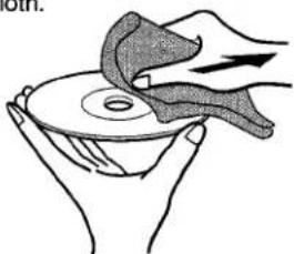
- When a disc becomes dirty, wipe the disc from the center out with a cleaning cloth.
natural_image
Illustration of hands holding a disc with a curved object above, no text or symbols present• After playing a disc, store the disc in its case. Do not leave the disc in places that are hot or humid.
Care of tapes
- Store tapes in their cases after use.
- Do not leave tapes near magnets, motors, television sets, or any source of magnetism. This will downgrade the sound quality and cause noise.
- Do not expose tapes to direct sunlight, or leave them in a car parked in direct sunlight.
TROUBLESHOOTING GUIDE
If the unit fails to perform as described in these Operating Instructions, check the following guide.
GENERAL
There is no sound.
• Is the AC cord connected properly?
• Is there a bad connection? (→ page 4)
- There may be a short circuit in the speaker terminals.
→ Disconnect the AC cord, then correct the speaker connections.
- Was an incorrect function button pressed?
Sound is emitted from one speaker only.
• Is the other speaker disconnected?
The output sound is not stereo.
• Is the Karaoke function turned on? (→ page 23)
An erroneous display or a malfunction occurs.
→ Reset the unit as stated below.
TUNER SECTION
There is constant, wave-like static.
• Is the antenna connected properly? (→ page 4)
- Is the signal weak?
→ Connect an outdoor antenna.
The reception contains noise interferences or the sound is distorted.
- Is the system picking up external noise or multipath distortion?
→ Change the orientation of the antenna.
→ Move the unit away from other electrical appliances.
CASSETTE DECK SECTION
The tape does not run.
• Is deck 2 in pause mode? (→ page 13)
The sound is off-balance or not adequately high.
• Is the playback head dirty? (→ page 29)
Recording is not possible.
- Is the erasure prevention tab on the tape broken off? (→ page 14)
• Is the recording head dirty? (→ page 29)
Erasure is not possible.
• Is the erasure head dirty? (→ page 29)
• Is a metal tape being used?
High frequency sound is not emitted.
- Is the recording/playback head dirty? (→ page 29)
CD PLAYER SECTION
The CD player does not play.
- Is the disc correctly placed? (→ page 15)
• Is the disc dirty? (→ page 29)
To reset
If an unusual condition occurs in the display window or the cassette decks, reset the unit as follows.
1 Press POWER to turn off the power.
2 Press POWER to turn the power back on while pressing ■ CLEAR. Everything stored in memory after purchase is canceled.
If the power cannot be turned off in step 1 because of a malfunction, reset by disconnecting the AC cord, and connect it again. Then carry out step 2.
SPECIFICATIONS
Main unit CX-NMT520
| FM tuner section | |
| Tuning range | 87.5 MHz to 108 MHz |
| Usable sensitivity (IHF) | 13.2 dBf |
| Antenna terminals | 75 ohms (unbalanced) |
| AM tuner section | |
| Tuning range | 530 kHz to 1710 kHz (10 kHz step) |
| 531 kHz to 1602 kHz (9 kHz step) | |
| Usable sensitivity | 350 μV/m |
| Antenna | Loop antenna |
| Amplifier section | |
| Power output | Front |
| 40 W + 40 W (50 Hz - 20 kHz, THD less than 1%, 6 ohms) | |
| Rear (Surround) | |
| 20 W + 20W (50 Hz - 20 kHz, THD less than 1%, 8 ohms) | |
| Center | |
| 20 W (50 Hz - 20 kHz, THD less than 1%, 8 ohms) | |
| Total harmonic distortion | 0.1 % (30 W, 1 kHz, 6 ohms, DIN AUDIO/Front) |
| Inputs | VIDEO/AUX: 150 mV (adjustable) |
| MD: 150 mV (adjustable) | |
| MIC 1, MIC 2: 1.0 mV (10 kohms) | |
| 5.1CH INPUT | |
| FRONT (L,R): 400 mV | |
| REAR (L,R): 270 mV | |
| CENTER: 270 mV | |
| SUB WOOFER: 400 mV | |
| Outputs | LINE OUT: 200 mV |
| SUB WOOFER: 1.0 V | |
| SPEAKERS: accept speakers of 6 ohms or more | |
| SURROUND SPEAKERS: accept speakers of 8 ohms to 16 ohms | |
| CENTER SPEAKER: accept speakers of 8 ohms or more | |
| PHONES (stereo jack): accepts headphones of 32 ohms or more | |
| Cassette deck section | |
| Track format | 4 tracks, 2 channels stereo |
| Frequency response | 50 Hz - 15000 Hz |
| Recording system | AC bias |
| Heads | Deck 1:Playback head × 1 |
| Deck 2: Recording/playback head × 1, erase head × 1 | |
Compact disc player section
| Laser | Semiconductor laser ( λ = 780 nm) |
| D-A converter | 1 bit dual |
| Signal-to-noise ratio | 85 dB (1 kHz, 0 dB) |
| Harmonic distortion | 0.05 % (1 kHz, 0 dB) |
| Wow and flutter | Unmeasurable |
General
| Power requirements | 120 V AC, 60 Hz |
| Power consumption | 160 W |
| Dimensions of main unit (W × H × D) | 260 × 329.1 × 344.5 mm(10 1/4 × 13 × 13 5/s in.) |
| Weight of main unit | 7.6 kg (16 lbs 12 oz.) |
Speaker system SX-NA502
| Cabinet type | 3 way, bass reflex (magnetic shielded type) |
| Speakers | Woofer:140 mm ( 63/8 in.) cone typeTweeter:60 mm ( 23/8 in.) cone typeSuper tweeter:10 mm ( 13/16 in.) ceramic type |
| Impedance | 6 ohms |
| Output sound pressure level | 87 dB/W/m |
| Dimensions (W × H × D) | 235 × 324 × 250 mm( 93/8 × 127/8 × 97/8 in.) |
| Weight | 3.3 kg (7 lbs 4 oz.) |
Specifications and external appearance are subject to change without notice.
BBE SYSTEM
The word "BBE" and the "BBE symbol" are trademarks of BBE Sound, Inc.
Under license from BBE Sound, Inc.
DOLBY PRO LOGIC
Manufactured under license from Dolby Laboratories Licensing Corporation.
"DOLBY", the double-D symbol □□ and "PRO LOGIC" are trademarks of Dolby Laboratories Licensing Corporation.
COPYRIGHT
Please check the laws on copyright relating to recordings from discs, radio or external tape for the country in which the machine is being used.
NOTE
This equipment has been tested and found to comply with the limits for a Class B digital device, pursuant to Part 15 of the FCC Rules. These limits are designed to provide reasonable protection against harmful interference in a residential installation.
This equipment generates, uses, and can radiate radio frequency energy and, if not installed and used in accordance with the instructions, may cause harmful interference to radio communications. However, there is no guarantee that interference will not occur in a particular installation. If this equipment does cause harmful interference to radio or television reception, which can be determined by turning the equipment off and on, the user is encouraged to try to correct the interference by one or more of the following measures:
- Reorient or relocate the receiving antenna.
- Increase the separation between the equipment and receiver.
- Connect the equipment into an outlet on circuit different from that to which the receiver is connected.
- Consult the dealer or an experienced radio/TV technician for help.
CAUTION
Modifications or adjustments to this product, which are not expressly approved by the manufacturer, may void the user's right or authority to operate this product.
PARTS INDEX
INDICE DE LAS PARTES
NOMENCLATURE


Name/Nombre/Nom
Page/Página/Page
①SYNCHRO DUBBING 18
●REC/REC MUTE 17,19,20
②DOLBY PRO LOGIC 21,22
③ TAPE DECK 1/2 .... 13,14,18 TUNER BAND .... 11,12 VIDEO/AUX/5.1 CH .... 22,27,28 CD .... 15,19,20 MD .... 27
④POWER 6,26,27 DEMO 6
⑤KARAOKE 23
⑥BBE 7 T-BASS 7
⑦PHONES 8
⑧ CD EDIT/CHECK 15,19,20,24
9 CLEAR....6,12-20,24,25 ◀▶PRESET....6,12-16,24 ■SET....12,13,15,17,25,26 ◀◀/◀◀DOWN....11-16,19-22,25-28 ▶◀/▶▶UP....11-16,19-22,24-28
⑩DISC DIRECT PLAY 1-3 .... 15,19,20 DISC CHANGE.... 15 ▲OPEN/CLOSE.... 15
⑪ ENTER 9,11
⑫ ECHO 23
⑬VOLUME 7,23
⑭MIC 23
15 GEQ 8,9 LOW 9 HIGH 9
16 SURROUND .... 10,11 DELAY .... 10,11 EFFECT .... 10,11
Name/Nombre/Nom
Page/Página/Page
⑰ MIC 1, 2....23
⑱ DISP 6
19 MULTI JOG 6-12,15,19,20,25,26
20 TIMER 26
CLOCK 25
For assistance and information
call toll free 1-800-BUY-AIWA (United States and Puerto Rico)
- COMPACT DISC STEREO SYSTEM SISTEMA ESTEREO CON REPRODUCTOR DE DISCOS COMPACTOS CHAINE STEREO AVEC LECTEUR DE DISQUES COMPACTS
- NSX-MT520
- OPERATING INSTRUCTIONS MANUAL DE INSTRUCCIONES MODE D'EMPLOI
- WARNING
- Explanation of Graphical Symbols:
- Owner's record
- PRECAUTIONS
- Installation
- Electric Power
- Outdoor Antenna
- Maintenance
- Damage Requiring Service
- TABLE OF CONTENTS
- PREPARATIONS
- SOUND
- RADIO RECEPTION
- TAPE PLAYBACK
- CD PLAYING
- RECORDING
- DOLBY PRO LOGIC
- SETTING UP
- NOTE
- CONNECTIONS
- Connect the supplied antennas.
- Connect the front speakers.
- Connect the surround speakers.
- Connect the center speaker.
- Connect the video equipment.
- Connect the Television to the video equipment.
- Connect the AC cord to an AC outlet.
- To position the antennas
- FM feeder antenna:
- AM antenna:
- To stand the AM antenna on a surface
- To mount the surround speakers on the wall
- CONNECTING AN OUTDOOR ANTENNA
- REMOTE CONTROL
- Inserting batteries
- When to replace the batteries
- Using the remote control
- BEFORE OPERATION
- To turn the power on
- To turn the power off
- Flash windows
- To dim the illumination of the display
- To change the spectrum analyzer display
- Game Demo
- To cancel the game Demo
- To play the game Demo
- To reset the game Demo
- AUDIO ADJUSTMENTS
- VOLUME
- Turn VOLUME on the main unit, or press VOLUME on the remote control.
- To change the left/right balance
- BBE SYSTEM
- Press BBE.
- SUPER T-BASS SYSTEM
- Press T-BASS.
- GRAPHIC EQUALIZER
- SELECTING THE PROGRAMMED EQUALIZATION CURVE
- Using the headphones
- Sound adjustment during recording
- To cancel the selected mode
- SETTING A NEW EQUALIZATION CURVE MANUALLY
- MEMORIZING THE NEW EQUALIZATION CURVES
- DSP SURROUND
- SELECTING A PROGRAMMED DSP SURROUND MODE
- Press SURROUND, and turn MULTI JOG to select the desired Programmed mode within 4 seconds.
- To display the current DSP SURROUND mode
- When the music source is monaural
- DELAY (delay time)
- To adjust the delay time
- L-R, L+R (input mode)
- To select a input mode
- FB (feedback level)
- To adjust the level of feedback
- To adjust the volume of the surround speakers
- MANUAL TUNING
- PRESETTING STATIONS
- PRESET NUMBER TUNING
- BASIC OPERATIONS
- To select a playing deck
- MUSIC SENSOR (deck 1 only)
- About cassette tapes
- LOADING DISCS
- PLAYING DISCS
- To play with the remote control
- To check the remaining time
- Selecting a track with the remote control
- Replacing discs during play
- RANDOM /REPEAT PLAY
- RANDOM play
- REPEAT play
- Press RANDOM/REPEAT.
- PROGRAMMED PLAY
- Press PRGM twice in stop mode.
- Press DISC DIRECT PLAY, then press numbered buttons 1-3 within 3 seconds to select a disc.
- Press numbered buttons 0-9 and +10 to program a track.
- Repeat steps 2 and 3 to program other tracks.
- Press ◀▶ to start play.
- To check the program
- To clear the program
- To add tracks to the program
- To change the programmed tracks
- To play the programmed tracks repeatedly
- BASIC RECORDING
- Preparation
- Insert the tape to be recorded on into deck 2.
- Press function (CD, TUNER, VIDEO/AUX or MD) and prepare the source to be recorded.
- Press ● REC/REC MUTE to start recording.
- To start recording with the remote control
- INSERTING BLANK SPACES
- To insert a blank space of less than 4 seconds, press REC/REC MUTE again while REC is flashing.
- To erase a recording
- DUBBING A TAPE MANUALLY
- Press TAPE.
- Insert the original tape into deck 1 and the tape to be recorded on into deck 2.
- Press TAPE DECK 1/2 to select deck 1.
- Press ● REC/REC MUTE to start recording.
- To stop dubbing
- DUBBING THE WHOLE TAPE
- Press SYNCHRO DUBBING to start recording.
- AI EDIT RECORDING
- Insert the tape into deck 2.
- Press CD and load the disc(s).
- Press CD EDIT/CHECK once.
- Press DISC DIRECT PLAY 1-3 to select a disc.
- Press numbered buttons 0-9 on the remote control to designate the tape length.
- Press ● REC/REC MUTE to start recording on the first side.
- Press CD EDIT/CHECK to display the program for the second recording.
- Turn over the tape in deck 2 and press ● REC/REC MUTE to start recording on the second side.
- To stop recording
- To clear the edit program
- To check the order of the programmed track numbers
- To add tracks from other discs to the edit program
- Time on cassette tapes and editing time
- PROGRAMMED EDIT RECORDING
- Check the following:
- Press DOLBY PRO LOGIC to select "NORMAL".
- Press MANUAL SELECT (TEST) and hold it down for about 4 seconds until "L" flashes.
- Adjust the sound level of the center and the surround speakers.
- Press MANUAL SELECT (TEST) again to stop the noise signal.
- About the channels
- To change the delay time
- PLAY WITH DOLBY PRO LOGIC
- Press VIDEO/AUX/5.1 CH and start playback of the video source.
- To cancel Dolby Pro Logic mode
- To change the sound levels during playback
- ADDITIONAL DOLBY PRO LOGIC MODES
- To select PHANTOM or 3 STEREO
- MICROPHONE MIXING
- VOCAL FADER/MULTIPLEX FUNCTIONS
- KARAOKE PROGRAM
- To check the reserved tracks
- To stop play
- To skip a current track
- To clear all the reservations
- SETTING THE CLOCK
- SETTING THE SLEEP TIMER
- SETTING THE TIMER
- TIMER RECORDING
- CONNECTING OPTIONAL EQUIPMENT
- VIDEO/AUX JACKS
- When connecting a turntable
- MD JACKS
- LINE OUT JACKS
- CD DIGITAL OUT (OPTICAL) JACK
- SUB WOOFER JACK 📁 JACK
- CH INPUT JACKS
- LISTENING TO EXTERNAL SOURCES
- Press VIDEO/AUX/5.1 CH or MD.
- Play the connected equipment.
- To change a source name in the display
- To adjust the sound level of the external source
- CONNECTING A DVD PLAYER
- To adjust the sound levels of the center and surround speakers in DOLBY DIGITAL SURROUND
- CARE AND MAINTENANCE
- To clean the cabinet
- To clean the heads and tape paths
- To demagnetize the heads
- Care of discs
- Care of tapes
- TROUBLESHOOTING GUIDE
- GENERAL
- TUNER SECTION
- CASSETTE DECK SECTION
- CD PLAYER SECTION
- To reset
- SPECIFICATIONS
- COPYRIGHT
- CAUTION
- PARTS INDEX
- INDICE DE LAS PARTES
- NOMENCLATURE
- Name/Nombre/Nom
- Page/Página/Page
Brand : AIWA
Model : NSX-MT520
Category : CD Player