
131 Marine - Pregnant BOSE - Free user manual and instructions
Find the device manual for free 131 Marine BOSE in PDF.

| Product Type | Marine Speaker System |
| Brand | Bose |
| Model | 131 Marine |
| Speaker Driver | One 4.5" (11.4 cm) full-range environmental driver per enclosure |
| Impedance | 4 - 8 ohms |
| Power Handling (Continuous) | 40W per IEC |
| Compatible Amplifier Power | 10 - 80 watts per channel |
| Weight (unpacked) | 9 lb (4 kg) |
| Dimensions (L x D) | 12" x 3.5" (30 cm x 8.9 cm) |
| Cut-out Diameter (Rear Mount) | 5-3/8" (13.7 cm) |
| Cut-out Diameter (Front Mount) | 7-1/8" (18 cm) |
| Grille Diameter | 8" (21 cm) |
| Mounting Depth | 3.5" (8.9 cm) |
| Mounting Wall Thickness (Rear) | 0.75" (1.9 cm) maximum |
| Mounting Wall Thickness (Front) | 0.5" (1.2 cm) maximum |
| Grille Finish | Arctic White |
| Enclosure Material | Polypropylene (dual-port) |
| Driver Cone Material | Polymer fiber |
| Quality Control | Syncom II computer testing |
| Warranty | 3-year limited transferable |
| Compliance | CE, EMC Directive 89/336/EEC |
| Included Accessories | 2 speaker cables (18-gauge, 20 ft each), mounting flanges, grilles, template, wire nuts, screws |
| Maintenance | Clean grilles with soft cloth dampened with mild detergent; avoid forcing water into ports |
| Safety Notes | Mount on bulkhead only; keep 3 ft (0.9 m) away from compass; not for automotive use |
| Repairability | Contact Bose dealer or customer service for service; no user-serviceable parts |
Frequently Asked Questions - 131 Marine BOSE
User questions about 131 Marine BOSE
0 question about this device. Answer the ones you know or ask your own.
Ask a new question about this device
Download the instructions for your Pregnant in PDF format for free! Find your manual 131 Marine - BOSE and take your electronic device back in hand. On this page are published all the documents necessary for the use of your device. 131 Marine by BOSE.
USER MANUAL 131 Marine BOSE
The Bose ^® 131 ^™ Marine Speaker System
Owner's Guide
Please read this owner's guide
The Bose ^® 131 ^™ marine speaker system is engineered to provide sound quality far beyond other marine speaker systems. This guide helps you install and use your speaker system properly. Please read the installation section completely before cutting any holes. It is important to understand the reasons for choosing one mounting hole size over the other.
Warranty period
Bose 131 marine speakers are covered by a limited 3-year transferable warranty. Details of the coverage are provided on the warranty card that came with your speakers. Please fill out the information section on your card. Then detach the card, and mail it to Bose Corporation.
Technical information
Features
• Polymer fiber driver cone
- Dual-port polypropylene enclosure
- Syncom II ^40 computer quality control
Speaker driver complement
- One 4 12 " (11.4 cm) full range environmental driver per enclosure
Compatibility/Impedance
• Maximum continuous power per I.E.C.: 40W
- Compatible with receivers or amplifiers 10 - 80 watts per channel
- Impedance 4 - 8 ohms
Finish
- Grille: Arctic White
Size/Dimensions
• W eight, unpacked: 9 lb (4 kg)
- 12"L x 3^1/2 "D (30 cm x 8.9 cm)
- Cut out Diameter:
- 5^3/8 (13.7 cm) with access to rear of mounting surface
- 7^1/8 (18 cm) without access to rear of mounting surface
- Grille Diameter: 8" (21 cm)
- Mounting Depth: 3^1/2 (8.9 cm)
- Mounting Wall Thickness: .75" (1.9 cm maximum) rear mounting .50"(1.2 cm maximum) front mounting
For your records...
Serial numbers are located on the label of each 131 marine speaker.
Serial numbers: ____ and ____
Dealer name: ____
Dealer phone: ____ Purchase date: ____
We suggest you keep your sales slip and warranty card together with this owner's guide.
Where to find...
Setting up
Unpack the carton 4
Tools required 4
Select the locations for your speakers 5
Installing Your Speakers
Test the speakers 6
Mounting the speakers 6
Installation from the rear of the bulkhead 7
Installation from the front of the bulkhead 11
Maintaining Your Speakers
Cleaning the speakers 16
Troubleshooting 16
Bose ^® Corporation ....inside back cover
CE
DECLARATION OF CONFORMITY
We, the offerer:
Bose® Corporation, The Mountain, Framingham, MA 01701-9168 USA
acknowledge our sole responsibility, that the product:
Kind of equipment: Loudspeaker Type designation: 131™ marine speaker system
in accordance with EMC Directive 89/336/EEC and Article 10(1) of the Directive, is in compliance with the following norm(s) or document(s):
Technical regulations: EN50081-1, EN50082-1 Accredited by Bose Corporation
23 January 1997
Bose B.V.
General Manager, Bose Europe Manufacturer's authorized EU representative
Unpack the carton
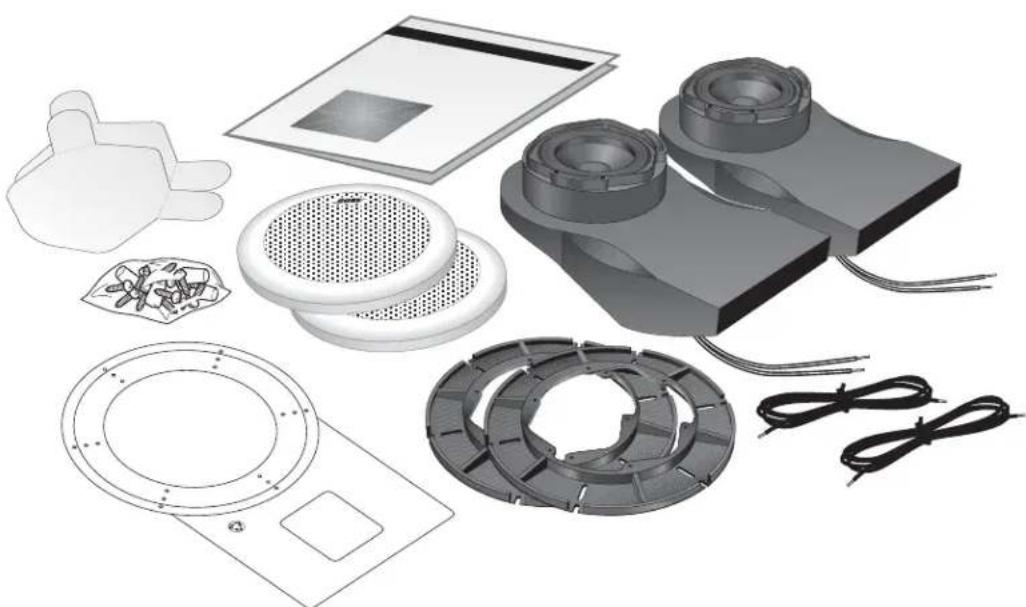
Carefully unpack your speakers and save all packing materials for possible future use. Do not attempt to use your speaker system if any part of it appears damaged. Notify Bose® Corporation or your authorized Bose dealer immediately. Check that your system contains the parts identified in Figure 1. For shipping, the mounting flange is packed inside its speaker grille. Separate these components before installation.
Notes: Please remove the perforated drilling and cutting template from the inner carton containing the grille and mounting flange. Also remove the perforated speaker cone shields from the inner cartons containing the enclosures. You will need the template and shields during installation.
Now is a good time to record each speaker serial number on page 2 of this guide and on your warranty card.
CAUTION: The 131 ^™ marine speakers are not intended to be installed in automobiles.
Figure 1
Packaging Contents:
• T wo 131 marine speaker enclosures
• T wo mounting flanges
• T wo speaker grilles
• One Owner's Guide
• One template for positioning, cutting, and drilling holes
• T wo speaker cone shields
- Mounting hardware:
• 30 screws (6 extra)
• 10 wire nut connectors (2 extra)
- Two 20 foot speaker cables, 18-gauge
Tools required
natural_image
Exploded view of industrial fan components including fans, vented fans, and electrical connectors (no text or symbols visible)You will need the following tools to complete this installation:
• Phillips-head screwdriver.
- An appropriate cutting tool for the surface to be cut. For installation in fiberglass or wood, we recommend a sabre saw. Use a short blade, and have some extra blades available. A hole saw may also be used. Large diameter hole saws are available and they allow you to make circular cuts on a flat surface.
- Drill with the following bits:
- For drilling the screw holes a 332 inch (.24 cm) bit is preferred, but you could also use a 18 (.32 cm) inch bit.
- For drilling the starter hole, use a 516 inch (.8 cm) bit.
- Center punch or awl.
- Half-round file or rasp.
- Eye and ear protection; dust mask.
CAUTION: Failure to follow these instructions voids all warranties on your speakers. If you are unsure of your ability to complete this process, consult a professional installer. Please read this owner's guide completely before beginning installation.
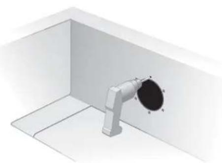
Select the locations for your speakers
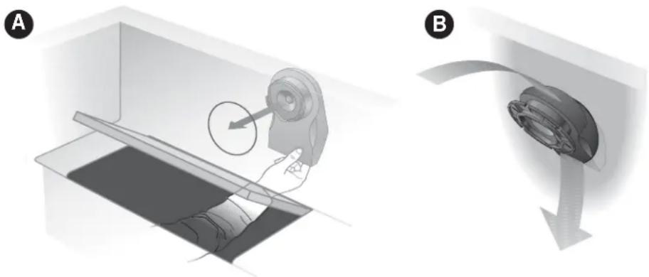
In selecting locations for your speakers, understand that there are two possible mounting options. It is easiest to mount the speakers from behind the mounting surface. However, if you cannot reach behind the mounting surface, you may cut a larger hole that allows you to insert the speaker enclosure from the front of the mounting surface. See Figure 2. With this in mind, find a location that:
- Allows sufficient room to snap on the grille. Use the template to be sure there is enough area around the holes you will cut in the bulkhead.
- Allows sufficient room for the speaker enclosure behind the bulkhead. During installation, the enclosure requires 4^1/2 inches (11 cm) of mounting depth. However, once installed the enclosure requires only 3^1/2 inches (9 cm) of mounting depth and 12 inches (31 cm) of extension. The enclosure may be rotated in a complete circle, but attaches to the mounting flange in only one position.
- Accommodates the speaker wire provided. Lay out lengths of wire that comfortably reach from the receiver to each speaker. Be sure the wires are secure and protected from being pinched, pulled, or damaged in any way.
- Is not close enough to adversely affect any compass.
Note: The magnets in the speakers will affect a boat compass. Avoid mounting the speakers closer than three feet from the compass. If necessary, a marine installer can help correct any deviation.
Figure 2
Selecting the right locations
A. Mount from the rear if you can insert the speaker enclosure behind the bulkhead mounting surface.
B. Mount from the front if you cannot reach behind the mounting surface. If you are uncertain about the depth and clearance behind your mounting surface, consult your boat manufacturer or dealer.
natural_image
Two-step diagram showing a hand operating a device in a container, with no visible text or symbols.
Note: Before going any further with your assembly, choose one of the methods described in Figure 2 above. The instructions for A begin on page 7; B on page 11.
Test the speakers
It is a good idea to test your system before installation. With the power turned off, connect the receiver to the speakers.
The provided speaker cord consists of two insulated wires; one is marked or ribbed, and is always positive (+). The plain wire is always negative (−). The wires correspond to the red (+) and black (−) terminals on the back of the speaker, receiver, or amplifier. Place the stripped end of the positive (+) right channel receiver wire together with the stripped end of the positive (+) right speaker wire. Then place the stripped end of the negative right channel receiver wire together with the stripped end of the negative right speaker wire. Repeat this procedure for the left speaker.
Be sure to connect each wire to the proper terminal (positive to positive, negative to negative). For this test, just twist the wire ends together. You will use the supplied wire nuts for the permanent connections.
When you are satisfied that everything works, disconnect the speakers and continue with the installation.
Mounting the speakers

CAUTION: Be sure to mount your 131 ^™ marine speakers on a bulkhead only. Do not cut holes in the hull. We recommend you consult a marine installer before drilling or cutting any holes. Choose a safe spot for drilling. Do not mount the speakers on surfaces with concealed hazards, such as electrical conduits or plumbing.
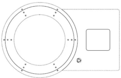
The cutting and drilling template
Locate the cutting and drilling template. It is perforated into the inner carton that contained your grilles and mounting flanges. The template has four functions.
- It helps you position the speaker enclosure by showing how much room to provide for the extension of the enclosure behind the bulkhead.
- It shows you how much room to allow for the snap on grille.
- It assists you in cutting the appropriate hole size in the bulkhead wall.
- It helps you drill the mounting screw holes in the bulkhead.
The template has two punch-out hole diameters. Use the smaller size for installation from behind the bulkhead. Use the larger for installation from the front. See Figures 2 & 3.
Figure 3
The template
natural_image
Pure diagram of concentric circles and a rectangle with dots, no text or symbols present
Installation from the rear of the bulkhead
Choose the 538 inch (13.6 cm) diameter hole size if you can comfortably hold the speaker enclosure from behind the wall while installing screws from the front. This is the preferred mounting method. If the hole you cut is not perfect, any slight overcut will be hidden by the grille.
A 1 Determine that there is enough room by reaching into the mounting area and sweeping with your hand. Determine where you will drill the hole for the speaker. You should also experiment by placing the speaker enclosure behind the bulkhead before making your final selection. Any orientation of the speaker enclosure is acceptable.
CAUTION: Determine whether any obstacles exist behind the mounting surface. To be certain, contact your boat manufacturer or dealer. Also, be certain that the enclosure will fit within the mounting area before drilling any holes.
A2 The round outer edge of the template shows how much room to allow for the grille. The long end is used to plan for room for the enclosure behind the bulkhead. There are two perforated circles in the template. Snap out the smaller one.
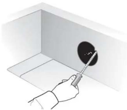
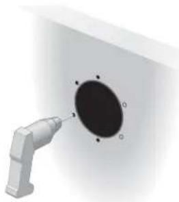
A 3 Place the template over the area where the speaker is to be located and mark the 5^3/6 inch (13.6 cm) hole with a metal scribing tool or pencil.
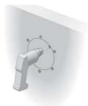
A 4 Drill a starter hole that is large enough for your sabre saw blade. Be sure to drill inside and close to the line you have marked.
natural_image
Illustration of a hand pressing down on a tray with directional arrows indicating motion (no text or symbols)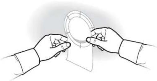
natural_image
Line drawing of two hands exchanging a circular object with a ring (no text or symbols)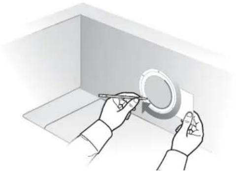
natural_image
Illustration of hands using a tool to mark a circular component inside a 3D box (no text or symbols)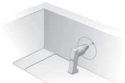
natural_image
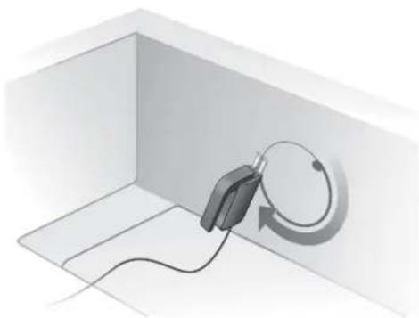
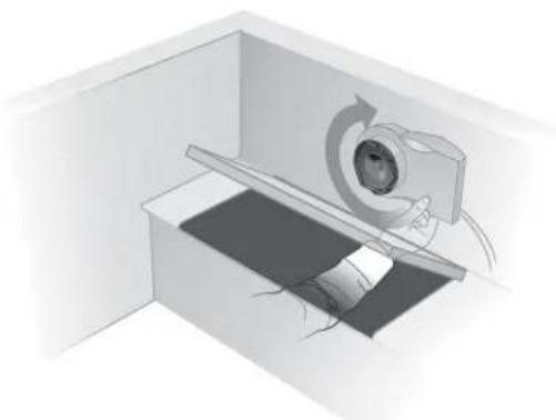
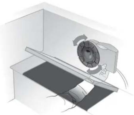
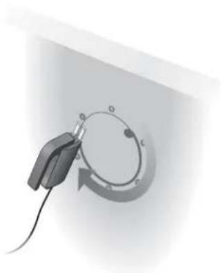
3D diagram of a mechanical component inside a rectangular chamber, showing a curved arm and a circular motion arrow (no text or symbols)A 5 Using the sabre saw, cut the hole for the speaker, carefully following the line. Take your time; you want a smooth-edged circular hole.
natural_image
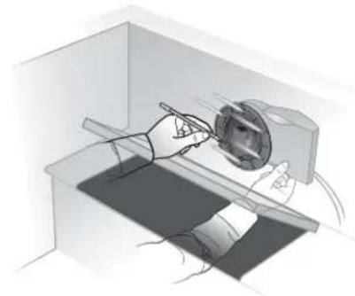
3D illustration of a device connected to a circular component in a rectangular room (no text or symbols)A 6 Use a half-round file or wood rasp to smooth out any roughness in the hole you have cut.
natural_image
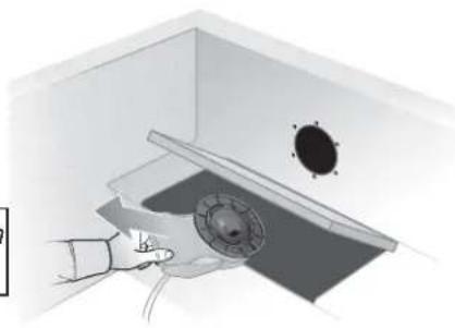
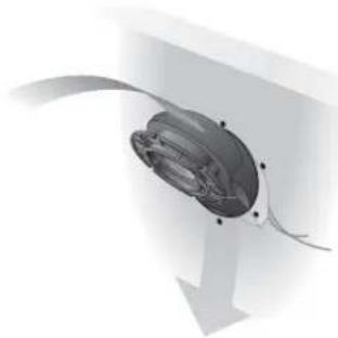
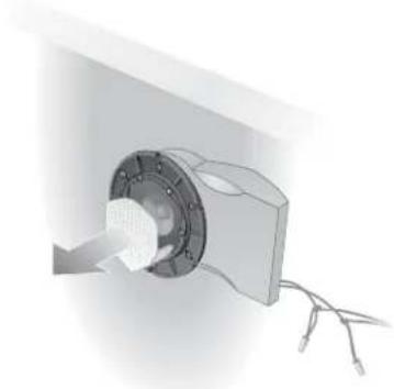
Hand using a tool to clean or store floor tiles in a low room (no text or symbols visible)A7 Hold the speaker enclosure up to the hole from behind the bulkhead and find the best position for the extended portion of the enclosure. Be sure the enclosure is hidden behind the bulkhead. If the enclosure does not fit, use the file or rasp to enlarge the hole.
natural_image
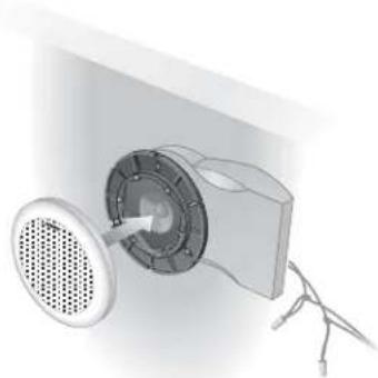
Diagram of a medical imaging device interacting with a patient's ear and surgical instrument (no text or labels)A8 Place the mounting flange so that it interlocks with the enclosure and is flush with the mounting surface.
natural_image
Diagram of a mechanical device with rotating components and a central circular component (no text or symbols)A9 Mark six screw holes. Use the smallest hole pattern that fits.
natural_image
Illustration of a person using a handheld device to interact with a device in a lab setting (no text or symbols visible)A 10 Remove the enclosure from behind the bulkhead.
natural_image
Illustration of a hand using a tool to clean or inspect a ceiling-mounted device (no text or symbols visible)CAUTION: Be sure the enclosure is not in place behind the bulkhead while drilling.
A 11 Drill the marked holes using a 18 inch (.32 cm) bit. Use a center punch to make a slight indentation for your drill bit. This will keep the drill bit from "walking" away from the mark you have made.
natural_image
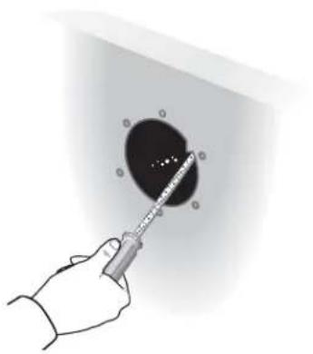
3D rendering of a pipe assembly with labeled components (A, B, C, N) inside a white room (no text or symbols beyond labels)A 12 You need to open one of the five marked drain holes because water can enter your 131^th marine speaker through the ports on the front of the enclosure.
Holding the enclosure in the mounting position you chose in Step 7, find the drain hole that will be at the lowest point when the speaker is mounted and break through the surface using a center punch, awl, or 1/8 inch (.32 cm) drill bit.
natural_image
Illustration of a hand using a tool to press or inspect a mechanical component (no text or symbols visible)CAUTION: Acoustic performance is reduced if the hole is larger than 18 inch (.32 cm) in diameter.
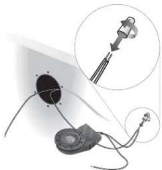
A 13 Connect the speakers. Be sure the receiver or amplifier is turned OFF. If possible, disconnect the power source. Use the supplied silicone-filled wire nuts to secure the ends of each wire pair. Place the stripped end of the positive (+) right channel receiver wire together with the stripped end of the positive (+) right speaker wire. Place the wire nut over the ends of the wires and turn it in a clockwise direction. Turn it with firm pressure until it stops; there should be no uninsulated wire visible. Repeat this procedure for the remaining wire end.
Repeat the above procedure for the left speaker.
Check that all connections are made positive to positive (+ to +) and negative to negative (- to -). Tighten any loose connections before you plug in the receiver or amplifier and turn it on.
natural_image
Diagram of a medical or laboratory setup with a device and a magnified inset showing a component (no text or symbols present)Note: Twisting the ends of the wires together is not necessary.
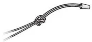
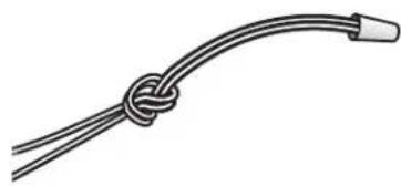
A 14 Tie a knot in each joined wire pair to protect the connection from being pulled apart.
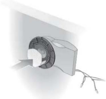
A 15 Remove the perforated speaker cone shields from the enclosure cartons. Insert the tabs of the shields into the speaker ports. This helps protect the speaker cone from potential damage during the installation process.
Note: For added protection against water entering the bulkhead, you can apply a generic silicone sealant between the flange and the mounting surface.
natural_image
Simple line drawing of a knotted cable or wire with two leads (no text or symbols)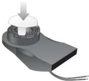
natural_image
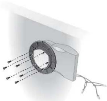
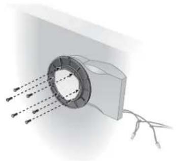
3D rendering of a mechanical component with a downward arrow and threaded base (no text or symbols)A 16 Replace the enclosure behind the bulkhead and place the mounting flange so that it interlocks with the enclosure and lines up with the drilled holes. Attach the flange to the mounting surface using six screws. Next, install six screws through the flange into the matching holes in the enclosure.
Note: If you plan to use a screw gun to install the screws, you should first set the gun to its lowest torque setting (do not exceed 12 inch-pounds or 135.84 N-cm of torque). If the screw does not seat properly, finish installing the screw at the next highest torque setting, or by hand.
natural_image
Diagram of a mechanical component with arrows indicating direction, no text or symbols presentA 17 Remove the speaker cone shield from the enclosure.
natural_image
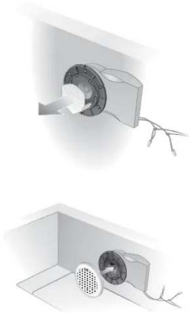
Two technical illustrations of a ceiling-mounted electrical component, one showing a rotary knob and wire, the other showing a fan installation with a perforated grille (no text or symbols)A 18 Snap the grille in place on the mounting flange. No hardware is needed to secure this part. You are now finished with the assembly. Enjoy your music system!
B Installation from the front of the bulkhead
If you cannot reach the mounting area from behind the bulkhead, you will have to mount the speaker enclosure by inserting it through the front. To do this you will need a 7 ^1/8 inch (18 cm) hole, the larger of the two perforated sections on your template.
CAUTION: Determine whether any obstacles exist behind the mounting surface. To be certain, contact your boat manufacturer or dealer. Also, be certain that the enclosure will fit within the mounting area before drilling any holes.
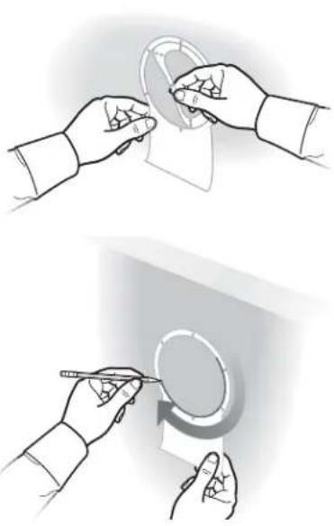
B 1 Place the template over the area where the speaker is to be located. The round outer edge shows how much room to allow for the grille. The long end is used to judge the room needed behind the bulkhead. There are two perforated circles in the template.
Snap out the larger one and mark the 7/8 inch (18 cm) hole with a metal scribing tool or pencil.
natural_image
Illustration of two hands performing a circular tool manipulation technique (no text or symbols present)B 2 Mark six screw holes from the largest hole pattern on the template, but do not drill yet. You may need to mark and drill a different set of holes along the same circle before finally attaching the flange.
Note: These markings are important to help keep the saw blade inside the line you have just drawn.
natural_image
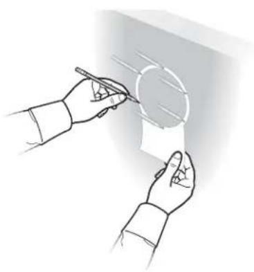
Illustration of two hands holding a paper with a pen, no text or symbols presentB 3 Drill a starter hole that is large enough for your sabre saw blade. Be sure to drill inside and close to the line you have marked.
natural_image
3D mechanical component with a curved arrow and circular features, no visible text or symbolsB 4 Using the sabre saw, cut the hole for the speaker, carefully staying just inside the line. Take your time; you want a smooth edged circular hole.
natural_image
Close-up of a handheld device with a circular button and cable, no visible text or symbolsCAUTION: Be sure to stay inside the line you have marked, and in particular, be sure to stay well inside the hole pattern you have marked. The marked holes, or others along the same circle, will be used to secure the speaker and must not be too close to the speaker hole. It is also important to stay inside the line because any error you make could be visible after the speaker grille is installed.
natural_image
Hand holding a syringe touching a circular object with holes, against a plain wall (no text or symbols visible)B 5 Use a half-round file or wood rasp to smooth out any roughness in the speaker hole you have cut.
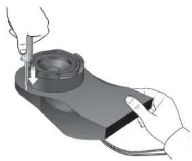
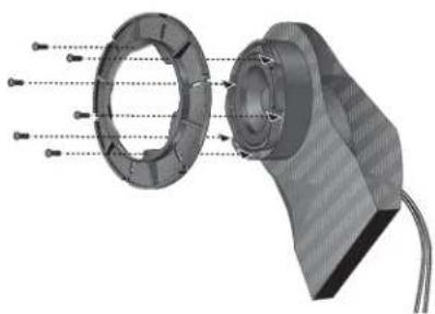
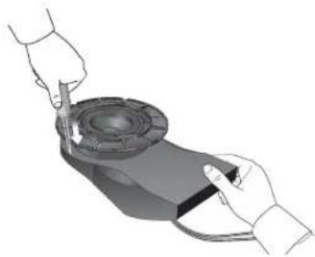
B 6 Attach the mounting flange to the enclosure using six screws.
natural_image
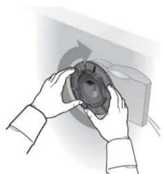
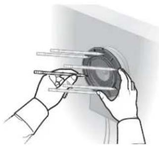
3D mechanical assembly diagram showing internal components with no visible text or symbolsB 7 Slide this assembly into the 7^1/8 inch (18 cm) hole and rotate the enclosure a full 360^ to determine the best mounting position for the extended portion of the speaker enclosure.
When you have determined the best position, take a moment to make careful note of it. Then, remove the speaker enclosure.
natural_image
Illustration of hands holding a speaker cone, no text or symbols presentB 8 You will need to open one of the five marked drain holes because water can enter your 131^TM marine speaker through the ports on the front of the enclosure.
Holding the enclosure in the mounting position you chose in Step 7, find the drain hole that will be at the lowest point when the speaker is mounted and break through the surface using a center punch, awl, or 18 inch (.32 cm) drill bit. Completing this task may require you to temporarily remove the flange from the enclosure.
natural_image
Illustration of a person using a handheld device to interact with a mechanical component (no text or symbols visible)CAUTION: Acoustic performance is reduced if the hole is larger than 18 inch (.32 cm).
B9 Connect the speakers. Be sure the receiver or amplifier is turned OFF. If possible, disconnect the power source.
Use the supplied silicone-filled wire nuts to secure the ends of each wire pair. Place the stripped end of the positive (+) right channel receiver wire together with the stripped end of the positive (+) right speaker wire. Place the wire nut over the ends of the wires and turn it in a clockwise direction. Turn it with firm pressure until it stops; there should be no uninsulated wire visible. Repeat this procedure for the remaining wire end.
Repeat the above procedure for the left speaker.
Check that all connections are made positive to positive (+ to +) and negative to negative (- to -). Tighten any loose connections before you plug in the receiver or amplifier and turn it on.
natural_image
Diagram of a medical or laboratory setup with a device connected to a circular component, showing a magnified inset (no text or symbols present)Note: Twisting the ends of the wires together is not necessary.
B 10 Tie a knot in each joined wire pair to protect the connection from being pulled apart.
natural_image
Simple line drawing of a rope tied with a curved cable (no text or symbols)B 11 Reinsert the enclosure into the wall in the position you determined in Step 7. If the outside circle of holes in the mounting flange line up with the ones you originally marked, remove the enclosure and drill at these marks. If they do not, make new markings that you can differentiate from your original set of markings.
natural_image
Illustration of hands holding a mechanical component with rods, no text or symbols presentB 12 Remove the speaker enclosure.
natural_image
Diagram of a mechanical component with a curved arrow indicating direction (no text or symbols)CAUTION: Do not drill while the speaker enclosure is in place.
B 13 Drill six 18 inch (.32 cm) holes.
natural_image
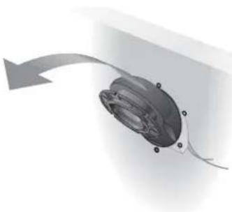
3D rendering of a mechanical component with a circular hole and a protruding rod (no text or symbols visible)B 14 Reinsert the speaker enclosure.
natural_image
3D rendering of a mechanical component with curved and linear features (no text or symbols visible)Note: For added protection against water entering the bulkhead, you can apply a generic silicone sealant between the flange and the mounting surface.
B 15 Remove the perforated speaker cone shields from the enclosure cartons. Insert the tabs of the shields into the speaker ports. This helps protect the speaker cone from potential damage during the installation process.
natural_image
3D rendering of a mechanical component with a central hub and wiring, no visible text or symbolsB 16 Install six screws, if possible. You need at least three screws installed and equally spaced.
Note: If you plan to use a screw gun to install the screws, you should first set the gun to its lowest torque setting (do not exceed 12 inch-pounds or 135.84 N-cm of torque). If the screw does not seat properly, finish installing the screw at the next highest torque setting, or by hand.
natural_image
Diagram of a mechanical component with arrows indicating direction and connection points (no text or symbols)B 17 Remove the speaker cone shield from the enclosure.
natural_image
3D rendering of a mechanical component with a central hub and wires, no visible text or symbolsB 18 Finally, snap on the grille to the mounting flange. No hardware is needed to secure this part. You are now finished with the assembly. Enjoy your music system!
natural_image
Diagram of a mechanical device with a circular component and a speaker emitting a fan (no text or symbols visible)Cleaning the speakers
Wipe the grilles using a soft cloth dampened with a mild detergent, such as dish soap. When cleaning near the speakers with a hose, be careful to avoid forcing water behind the grille, onto the driver, or into the acoustic ports.
No other regular maintenance is required.
Troubleshooting
If you have a problem with your 131 ^™ marine speakers, turn off your sound source and try the solutions below. If one of these solutions does not solve your problem, contact your Bose ^® dealer to arrange for service. Or, to contact Bose directly, refer to the inside back cover of this guide. Bose Corporation will make every effort to remedy any problem within the terms of your warranty.
| Problem What to do | |
| No sound | Make sure the boat's receiver is turned ON.Make sure the power supply of the boat is connected and adequately charged.Make sure the receiver is not set to MUTE.Refer to the owner's guide that came with your receiver.Check connections to both the speakers and the receiver.Refer to “Test the speakers” on page 6. Correct any connection errors. |
| No sound from one speaker | Disconnect the working speaker from the receiver.Switch the cord of the “faulty” speaker from its original receiver connections to the other set of connections (the working speaker was originally attached to those connections).- If the speaker now works, the problem is in your receiver.- If the speaker does not work, continue below.Remove the cord from the working speaker and connect it to the “faulty” speaker and either set of receiver connections.- If the speaker now works, the problem is in the original speaker cord.- If the speaker does not work, the problem is in the speaker. |
| One speaker sounds distorted | Follow the same procedure for the problem of no sound from one speaker, as outlined above. |
| Not enough bass or treble | Adjust the bass and treble controls on the receiver.Check the connections to make sure they are correctly in phase (+ to + and - to -). Refer to “Test the speakers” on page 6. |
USA
Bose Corporation, The Mountain
Framingham, MA 01701-9168
1-800-367-4008
Phone hours - ET (eastern time):
Weekdays 8:30 a.m. to 8 p.m.
Saturdays 9 a.m. to 3 p.m.
Canada
Bose Ltd., 1-35 East Beaver Creek Road
Richmond Hill, Ontario L4B 1B3
1-800-465-2673
Phone hours - ET (eastern time):
Weekdays 9 a.m. to 5 p.m.
European Office
Bose Australia, Inc., 1 Sorrell Street
Parramatta, N.S.W. 2150
TEL 02 204-6111 FAX 02 204-6122
Belgique/België
Bose N.V., Limesweg 2, B-3700 Tongeren
TEL 012-390800 FAX 012-390840
Danmark
Bose A/S, Industrivej 7, 2605 Brøndby
TEL 4343-7777 FAX 4343-7818
Deutschland
Bose Corporation India Private Limited
W-16, Greater Kailash-II
New Delhi 110 048
TEL (011) 648 4462 FAX (011) 648 4463
Ireland
Bose Corporation
Carrickmacross, Co Monaghan
TEL (042) 9661988 FAX (042) 9661998
Italia
Gillingham Business Park
Gillingham, Kent ME8 ONJ
TEL 0870-741-4500 FAX 0870-741-4545
From other locations
Bose Customer Service, 1 New York Ave.
Framingham, MA 01701-9168 USA
- The Bose ® 131 ™ Marine Speaker System
- Please read this owner's guide
- Warranty period
- Technical information
- Features
- Speaker driver complement
- Compatibility/Impedance
- Finish
- Size/Dimensions
- For your records...
- Where to find...
- Setting up
- Installing Your Speakers
- Maintaining Your Speakers
- CE
- DECLARATION OF CONFORMITY
- January 1997
- Unpack the carton
- Figure 1
- Packaging Contents:
- Tools required
- Select the locations for your speakers
- Figure 2
- Test the speakers
- Mounting the speakers
- The cutting and drilling template
- Installation from the rear of the bulkhead
- B Installation from the front of the bulkhead
- Cleaning the speakers
- Troubleshooting
- USA
- Canada
- European Office
- Belgique/België
- Danmark
- Deutschland
- Ireland
- Italia
- From other locations
Brand : BOSE
Model : 131 Marine
Category : Pregnant