
CD 111 USB - Car radio ECG - Free user manual and instructions
Find the device manual for free CD 111 USB ECG in PDF.


| Product Type | Car Stereo with CD and USB |
| Brand | ECG |
| Model | CD 111 USB |
| Dimensions (Approx.) | 180 x 50 x 100 mm (1 DIN standard) |
| Weight (Approx.) | 0.5 kg |
| Power Supply | 12V DC (negative ground) |
| Max Power Output | 4 x 20W RMS (typical) |
| Supported Media | CD, CD-R, CD-RW, USB flash drive |
| Radio Bands | FM, AM (MW/LW) |
| USB Playback | MP3 and WMA files |
| Equalizer | Preset EQ modes (Rock, Pop, Classic, etc.) |
| Display | LCD with backlight |
| Clock Function | Yes, with 12/24 hour mode |
| Remote Control | Included (infrared) |
| AUX Input | 3.5 mm jack on front panel |
| Cleaning Instructions | Wipe with a soft, dry cloth; avoid solvents |
| Safety Precautions | Use correct fuse rating; avoid moisture and extreme temperatures |
| Spare Parts / Repairability | Replaceable fuse; refer to authorized service for internal repairs |
| General Information | Includes ISO connector for easy installation |
Frequently Asked Questions - CD 111 USB ECG
User questions about CD 111 USB ECG
0 question about this device. Answer the ones you know or ask your own.
Ask a new question about this device
Download the instructions for your Car radio in PDF format for free! Find your manual CD 111 USB - ECG and take your electronic device back in hand. On this page are published all the documents necessary for the use of your device. CD 111 USB by ECG.
USER MANUAL CD 111 USB ECG
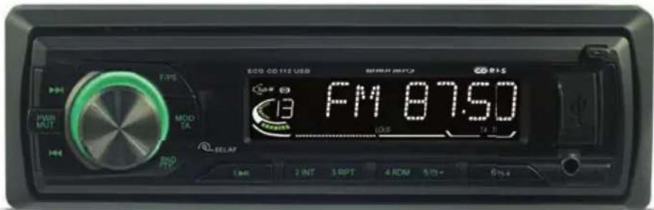
39 LED 602 PVR
AUTORÁDIO S USB/SD
NÁVOD K OBSLUZE
CZ
AUTORÁDIO S USB/SD
NÁVOD NA OBSLUHU
SK
CAR STEREO WITH USB/SD
INSTRUCTION MANUAL
EN
VSTUP AUX IN, VÝSTUP RCA OUT....10
ŘEŠENÍ POTÍŽÍ......11
TECHNICKÉ ÚDAJE 11
BEZPEČNOSTNÍ POKYNY
natural_image
Diagram showing two rectangular blocks with an arrow indicating direction (no text or symbols)natural_image
Diagram of a mechanical device with a spring and lever mechanism, showing hands operating the component (no text or symbols present)natural_image
Diagram showing a connector with pins and wires, no text or symbols presentnatural_image
Isometric diagram of a mechanical or architectural component with two rectangular blocks and directional arrows indicating movement (no text or symbols)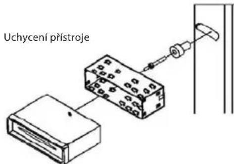
natural_image
Pure mechanical assembly diagram showing bolt holes and fasteners without any text or symbols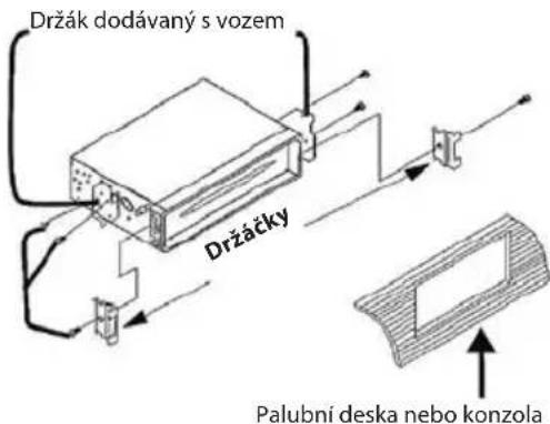
VSTUP AUX IN, VÝSTUP RCA OUT
1. Externí vstup
POUŽÍVANIE RDS....19
POUŽÍVANIE USB/SD....19
VSTUP AUX IN, VÝSTUP RCA OUT ....20
RIEŠENIE ŤAŽKOSTÍ 21
TECHNICKÉ ÚDAJE....21
BEZPEČNOSTNÉ POKYNY
natural_image
Diagram showing two rectangular blocks with an arrow indicating direction (no text or symbols)natural_image
Diagram of a mechanical device with a spring and lever mechanism, showing hands operating the component (no text or symbols present)natural_image
Isometric line drawing of a mechanical component with two rectangular parts and directional arrows indicating movement (no text or symbols)natural_image
Diagram showing a mechanical assembly with a bracket and a magnified view of a tool interacting with a component (no text or symbols present)- Jazýčky na montážnom držiaku vyhnite tak, aby držali montážny držiak pevne na mieste.
natural_image
Pure mechanical assembly diagram showing bolt holes and fasteners without any text or symbols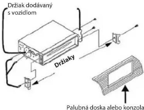
VSTUP AUX IN, VÝSTUP RCA OUT
1. Externý vstup
AUX IN, RCA OUT ....30
TROUBLESHOOTING....31
TECHNICAL SPECIFICATIONS....31
SAFETY INSTRUCTIONS
EN
Read carefully and keep for future use!
Warning: The safety measures and instructions, contained in this manual, do not include all conditions and situations possible. The user must understand that common sense, caution and care are factors that cannot be integrated into any product. Therefore, these factors shall be ensured by the user/s using and operating this appliance. We are not liable for damages caused during shipping, by incorrect use, voltage fluctuation or the modification or adjustment of any part of the appliance.
To protect against a risk of fire or electric shock, basic precautions shall be taken while using electrical appliances, including the following:
- Do not use an appliance with damaged power cables. All repairs including cord replacements shall be performed by a professional service centre! Do not remove protective covers of the appliance, risk of electric shock!
- Protect the appliance against direct contact with water and other liquids, to prevent potential electric shock.
- Pay close attention when using the car stereo while driving, do not increase the volume too much – it may result in the impaired hearing of outside noises and therefore driving safety as well. It is better to stop the vehicle for more complicated operations.
- After parking in very high or very low temperatures for a longer period of time, wait until the temperature to settle before turning the system on.
- Only use supplements/accessories specified by the manufacturer and in accordance with the instructions given in this manual. The manufacturer is not liable for damages caused by the improper use of this appliance.
- Use a soft and clean towel to clean the outer surface. Do not use chemicals or cleaning detergents for cleaning the system.
- This system shall not be used by persons (including children), whose physical, sense or mental inability or insufficient experience and skills prevent him from safely using the equipment, if they are not supervised or if they have not been instructed regarding the use of the equipment by a person responsible for their safety. Child supervision is essential to prevent them from playing with the system.
INSTALLATION
Installing car audio equipment can sometimes be difficult even for the most experienced installation technicians. If you are not sure how to handle electrical wires, remove and reassemble cover panels, upholstering, dashboard components and other parts of your car, have your equipment installed by a professional shop which will take care of the device installation.
IMPORTANT: Prior to the installation, remove the two transport screws from the top of the device.
Pre-installation warning
- Before installing, do not forget to disconnect the cable leading to the negative battery terminal to prevent a short-circuit.
- This device is designed for vehicles with 12 V batteries and negative ground. Before installing, make sure the vehicle uses a 12 V battery.
- Remove the top side of the device via the two transport screws before installing.
- The black wire is the ground wire. Quality grounding requires a solid connection to the car bracket. The connection area should be clean and rid of rust, paint or any other impurities. Ground this wire separately from devices with a large current consumption, such as power amplifiers. If you ground them together, the device will disconnect from the car bracket, potentially leading to damage or fire.
- Make sure the coloured wires are connected according to the diagram. Incorrect wiring can cause a defect on the device or damage the car electronics system. The wires of this device may have different colours than those of other appliances, despite having the same function. When connecting this device to another product, follow the installation manuals of both devices.
- Make sure the negative speaker wire is connected to the negative speaker terminal. Do not connect the negative speaker wire to the car bracket.
- The device is designed to operate with only 4 speakers. Do not combine outputs to accommodate for 2 speakers. Do not ground negative speaker wires to the car bracket.
- Speakers connected to this device must be high-performance units with a minimum nominal power output of 45 W and impedance of 4 to 8 Ohms. Connecting speakers with parameters other than those stated here can damage the device and speakers. Check the condition of the speakers – connecting this device to old or damaged speakers can lead to a defect that damages the circuitry of the system, resulting in the consumer losing his/her warranty for the device.
- If the device is installed inside a car without an ACC (accessories) position in the switch box, the red wire should be connected to the terminal interconnected with the ON/OFF function of the ignition key. Failing to do so could lead to depleting the battery once you have left the vehicle.
- Use clamps or tape to fixate the wires in place. Use tape to provide better protection in areas where wires touch metal objects. To prevent short-circuits, tape the ends of loose cables with insulation tape.
- All cables shall be guided and secured to avoid having them touch any moving parts, such as the stick shift or hand brake. Do not guide cables through areas exposed to extreme heat, such as heating vents. If the insulation melts or is damaged, the cable on the car bracket can short-circuit.
- Do not guide the yellow cable to the battery through the engine area. The cable insulation could become damaged and result in a very serious short-circuit.
- Do not short-circuit any wires. Doing so could render the proper function of the protection circuit impossible.
- Do not apply voltage to other appliances by cutting the insulation of the stereo power cord and connecting a wire intended for another appliance. This would result in exceeding the current capacity of the wire and overheating.
- Because the audio section of the appliance contains unique integrated circuits, do not install the system to have the speaker wires grounded directly or have one common wire for the left and right speaker.
-
When the system's power supply is activated, the control signal is transmitted over the orange wire. You can connect this signal to the input of an external amplifier remote control or automatic antenna control relay (up to 300 mA 12 Vdc). If the car is equipped with an antenna integrated within the glass, connect the terminal to the antenna amplifier power supply.
-
If an external power amplifier is used together with this device, do not connect the orange wire to the amplifier power terminal. Do not connect the orange wire to the automatic antenna power terminal either. This type of connection could result in excessive current consumption and serious damage. Detailed information for connecting a power amplifier and other systems can be found in the manual for the respective system. These instructions shall be followed for the wiring installation.
- Do not cover any air vents or the radiator panel. Risk of overheating and fire.
- Make sure the system is properly grounded to the car bracket. Good grounding eliminates most electrical interference. Quality grounding requires a solid connection to the car bracket. The ground connection point (car bracket) should be metal, cleaned of rust, paint, plastic or impurities, to ensure a good electrical connection.
- A choke may need installing into the power supply if there is apparent interference when you accelerate. Leave this installation to a professional service shop.
- When replacing a fuse, make sure to use a fuse with the same nominal value, as stated on the fuse socket. Do not replace blown fuses with fuses of different values. Seek professional help if you blow the fuse again.
- Before connecting the battery and activating the system, carefully check all connections are correct.
- After completing the installation and prior to using the device, connect the battery, then use a sharp object to press the reset button (RES) to reset the device to default settings. After pressing the button, wait a few seconds until the red light begins to flash.
Installation instructions:
- Choose a location to install the system that will not interfere while driving.
- Prior to final installation, try connecting the cables to check that all is duly connected and the car stereo and other systems work without any issues.
- Only use components supplied with the system to ensure proper installation. Using unapproved components can lead to defects.
- Refer to your nearest dealer should the installation require drilling holes or other adjustments inside the vehicle.
• Install the system so that it does not interfere with the driver and that it cannot injure passengers should the car come to a sudden stop, for example, in a critical situation. - Refrain from installing the system in places where it could be exposed to high temperatures, for example, direct sunlight or hot air from the heating system, or in places exposed to dust, impurities or excessive vibrations.
Remove the old device from the dashboard
Remove the exterior panel.
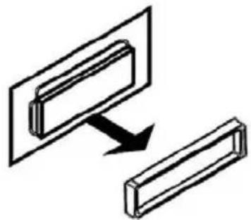
natural_image
Diagram showing two rectangular blocks with an arrow indicating direction (no text or symbols)Front assembly according to the DIN standard
Insert the installation keys, supplied with the old system, into the car stereo shaft along the side of the device (see illustration) until you hear a click. Pull on the keys and pull-out your old system from the dashboard.
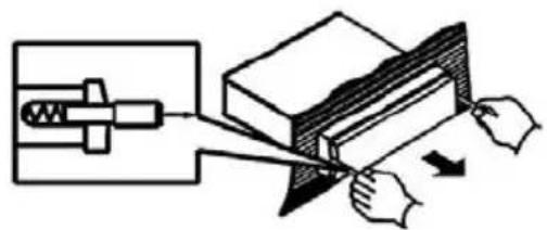
natural_image
Diagram of a mechanical device with hands operating it, showing motion and force direction (no text or symbols)DO NOT DISCONNECT THE WIRING AT THIS TIME!
Mark the polarity of the speaker wires
Marking the polarity of the speaker wires will make connecting the existing speakers to your cr stereo easier. Look over the wiring diagram before disconnecting the connectors of the old stereo. If you are not sure about the polarity of the existing speaker wires, install new wires or refer to a professional service shop for help.
Warning!
Before you start with the system installation, disconnect the terminal on the negative battery pole. See the your car manual for detailed instructions.
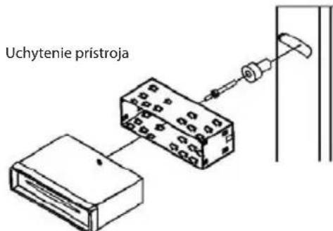
Front assembly according to the DIN standard (Method A)
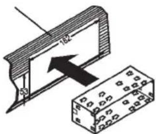
- After removing the old car stereo and its mounting frame, slide in the mounting frame supplied with this system.
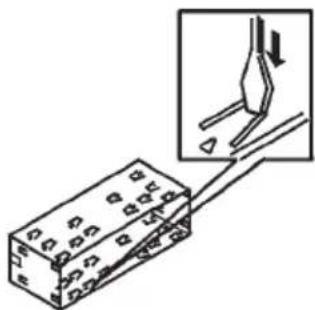
natural_image
Diagram showing a connector with pins and wires, no text or symbols present- Pull out the latches on the mounting frame to secure the mounting frame firmly in place.
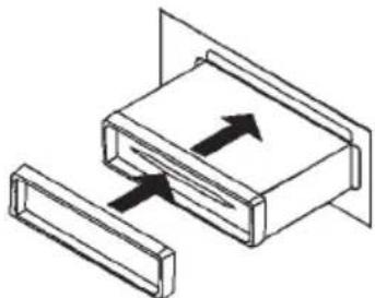
natural_image
Isometric diagram of a mechanical or architectural component with two rectangular blocks and directional arrows indicating movement (no text or symbols)- Connect the stereo connector with the car wires. See the wiring diagram. Slide in the car stereo into the dashboard. Then mount the exterior panel.
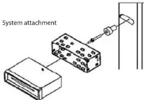
- Fix the stereo using the supplied back mounting screw and steel strip. See list of components.
Back assembly according to the DIN standard (Method B)
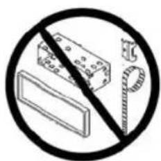
Note: The exterior panel, frame and metal strip are not used for the method B installation.
- Remove the frames on both sides.
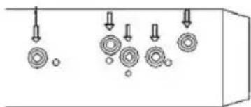
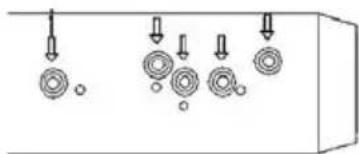
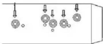
- Align the screw holes in the frame supplied with the car and the holes for the stereo screws. Tighten two screws on both sides of the system. Then fix the frame to the car.
- Connect the car wires to the stereo connector, see wiring diagram.
natural_image
Pure mechanical assembly diagram showing bolt holes and fasteners without any text or symbols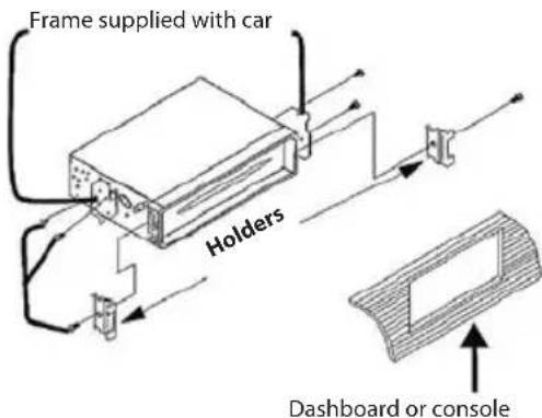
WIRING DIAGRAM
Make sure the car bracket is properly grounded. Good grounding eliminates most problems with electrical interference. Quality grounding requires a solid connection to the car bracket.
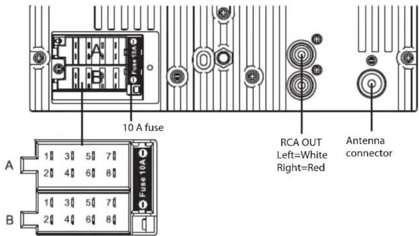
Connector A
- Speaker, back, right + (purple)
- Speaker, back, right - (purple/black)
- Speaker, front, right + (grey)
- Speaker, front, right - (grey/black)
- Speaker, front, left + (white)
- Speaker, front, left - (white/black)
- Speaker, back, left + (green)
- Speaker, back, left - (green/black)
Connector B
- Empty
- Empty
- Empty
- Continuous power +12V (yellow)
- Automatic antenna control (blue/white)
- Empty
- Boost converter (red)
- Ground (black)
EN
Speaker wiring notes
- Follow the diagram above when installing the car stereo with new or existing speakers.
• The car stereo is designed to be used with four (4) speakers with an impedance between 4 to 8 Ohms.
• A speaker impedance lower than 4 Ohms could damage the stereo. - Do not bridge or combine speaker wire outputs. If you are not using four speakers, use insulation take to insulate the ends of unused speaker wires, to prevent short-circuits.
- Do not connect the negative speaker terminal to the car bracket (ground).
BASIC CONTROLS
1. Power On/Off
Press POWER to start the system. Press the button again to power off the system.
2. Mode option
Press MODE to toggle between system modes.
3. Loudness
Press SEL repeatedly until "LOAD ON" or "LOAD OFF" is shown on the display. Turn the VOL dial to enable or disable the feature. The feature is enabled with "LOAD ON" is displayed.
4. Mute
Press MUTE to deactivate the sound. Press the button again to reactivate sound.
5. Volume
Turn the VOL dial to adjust the volume. Turn the volume control dial clockwise to increase the volume, counterclockwise to lower the volume. A higher number indicates a higher volume.
6. Bass
Press SEL repeatedly until "BAS" appears on the display. Turn the VOL volume dial to adjust the bass.
7. Treble
Press SEL repeatedly until "TRE" appears on the display. Turn the VOL volume dial to adjust the treble.
8. Balance left-right
Press SEL repeatedly until "BAL" appears on the display. Turn the VOL volume dial to adjust the balance between left and right channels. "L=R" on the display indicates the balance is in the middle.
9. Fade front-rear
Press SEL repeatedly until "FAD" appears on the display. Turn the VOL volume dial to adjust the balance between front and rear channels. "F=R" on the display indicates the balance is in the middle.
10. Equalizer
Press SEL repeatedly until "EQ" appears on the display. Then choose from the selection of equalizer effects. The following options are available: FLAT-ROCK-POP-CLASS.
11. Beep
Press SEL repeatedly until "BEEP" appears on the display. Turn the VOL volume dial and select "BEEP OFF" or "BEEP ON". When the feature is enabled (BEEP ON), a beep sound will emit each time a button is pressed.
12. Volume pre-set
Press and hold SEL for 2 seconds until "TA ALARM" is shown on the display. Press SEL repeatedly until "P-VOL" appears on the display. Turn the VOL volume dial to adjust the volume that will be the default volume each time the device starts.
13. Clock
Press and hold CLK, the time will appear on the display.
Press and hold the button until the time begins to flash. Turn the VOL volume dial to adjust the hour and press SEL to get the minutes flashing. Turn the VOL dial to adjust the minutes. Confirm the settings by pressing CLK.
CONTROLLING THE STEREO
1. Radio bandwidth selection
Press BND to enter the radio receiver features at any time.
The system offers 5 bands: three FM bands (FM1, FM2 and FM3) and two AM bands (AM1 and AM2). You can store up to six pre-set stations in each of the five bands. Up to 30 stations can therefore be stored in the system memory.
2. Tune / Scan
In Radio mode, press ">>|" or "|<<" once, the radio frequency will move further or back by one step.
Press and hold ">>|" or "|<<" and the receiver will scan for the next/previous radio station with a strong signal. Repeat to find additional stations with a strong signal.
3. Switching between stereo and mono reception
In FM mode, press SEL repeatedly until "MONO" or "STEREO" appears on the display. Turn the VOL dial and select the desired reception mode.
4. Storing pre-set stations
The system contains six buttons, which allow the user to directly tune stations stored in the memory. Up to 6 stations can be stored for each band. While listening to a radio station, to store the respective station as a pre-set on your device, press and hold one of the buttons labelled 1 through 6, until the pre-set number appears on the display. The station is now stored under this button.
5. Auto-store / scanning through pre-sets
A: Auto-scan and store
While listening to FM radio, press and hold F/PS for three seconds. The receiver will automatically scan through the frequency band and store stations with the strongest signal into the system.
While listening to AM radio, press and hold F/PS for three seconds. The receiver will automatically scan through the frequency band and store stations with the strongest signal into the system.
B: Scanning through stored stations
Press F/PS shortly to scan through stored stations. Stations in the FM band will be scanned under FM mode, stations in the AM band will be scanned under AM mode.
6. Local stations
Press SEL, repeatedly until "LOC" appears on the display. Turn the VOL dial and select "LOC ON" or "LOC OFF".
a: LOC ON indicates the local reception mode is enabled.
b: LOC OFF indicates remote stations will also be received. Depending on the region in which the system is being used, local or remote reception can make receiving radio broadcasting easier.
7. Receiver Reset
When the system is off, press and hold MOD+BND for 3 seconds. The receiver will be reset and all previously stored stations will be erased.
RDS
1. AF - Alternative Frequency
Press and hold SEL, the system will select the strongest FM signal of the tuned station, therefore you do not have to tune to another station when travelling through different coverage regions. The system is receiving RDS information when the AF light is on. When AF is flashing, the RDS information has not yet been loaded.
2. TA - Traffic Announcement
Press and hold TA to activate receiving traffic announcements from local radio stations.
To select a TA mode, press and hold SEL for 2 seconds, TA SEEK will appear on the display. Turn the volume dial to toggle between TA SEEK and TA ALARM and once you have made a selection, allow the system to activate the selected mode. Under TA SEEK mode, the system will search for traffic announcements once TA is pressed, under TA ALARM mode, TA/TP will appear and only alarm announcements will be active.
3. PTY - Program Type
The system allows you to select a specific type of program and searches for a station broadcasting this type of program. Press PTY once to display music genres. Then press either button 1-6 to select from the available genres.
Press PTY twice to display programs with spoken work content. Then press either button 1-6 to select from the available types. Each numerical button allows you to choose from three types of programs.
RDS-EON controls
This system is equipped with the newest EON feature (Enhanced Other Networks). When listening to the radio or CD, and a traffic report is available from a nearby local station, the radio already knows the frequency of this station and tunes into this station and increases the volume. CD playback is interrupted and the radio tunes to the traffic announcement station for the duration of the traffic announcement. Once the traffic report has ended, the system will return to its previous mode and is ready to receive the next traffic announcement.
USB/SD
Attention:
- Before playing content on this system, backup any important data stored on the memory card or USB memory device. Any unauthorized operations can result in data loss. The system manufacturer is not liable for any loss of data.
1. MP3/WMA playback from USB/SD
Insert the USB memory device / SD card into the USB / SD card slot. If there are no MP3 or WMA files on the USB device or SD card, "USB PLAY" or "SD MMC" will appear on the display.
2. Playback mode
You can select USB or SD/MMC mode by pressing MODE. "USB PLAY" means the system is in USB playback mode, whereas "SD/MMC" means the system is on SD card playback mode.
3. Track/folder search
a: Press >>| to move one track further, press |<< to move one track back.
b: Press F/PS once, the track number will begin to flash on the display. Turn the VOL dial to select the track number in this folder, press SEL to confirm your selection.
4. ID3
The track name will automatically appear on the display.
5. Play/pause
Once the USB device / SD card is loaded, the first track starts to play automatically. Press 1 PAU, "PAUSE" will begin to flash on the display.
6. INTRO
Press 2 INT to begin playing the first several seconds of each track from the USB / SD card. The display will show "INT+track number" and the first 10 seconds of the track will play before going to the next track, where the system will again play the first 10 seconds of the track, and so on. Press 2 INT again to stop the intro feature.
7. REPEAT
Press 3 RPT to repeat the track that is currently playing. The display will show "RPT+track number", indicating the track that will be repeated. Press 3 INT again to disable the repeat feature.
8. RANDOM
Press 4 RDM to play all files on the SD card / USB device in random sequence. The display will show "RDM+track number", indicating playback in random order. Press 4 INT again to stop the random playback feature.
9. Move forward one directory
Press 5 ☐- to move one folder forward.
10. Move back one directory
Press 6 + to move one folder back.
AUX IN, RCA OUT
1. Auxiliary input
The AUX IN connector can be found on the front panel. You can use this input to connect an external music source, such as an MP3 player or smartphone, to your car stereo using a stereo cable with a 3.5 mm jack. Press the MODE button to select AUX mode. Adjust the volume with the volume dial. Music playback is controlled on the external player.
2. RCA output
CINCH connectors are found on the back panel of the system (see wiring diagram). These allow connecting an external terminal amplifier, equalizer, or other audio equipment, requiring a pre-amplified input signal. Follow the installation instructions in the manual of the connected external audio system.
TROUBLESHOOTING
Before bringing the device to the repair centre, please check the cable wiring. Should problems continue even after applying the recommendations shown in this table, refer to the nearest authorized service centre.
| Symptom Cause/Solution | |
| No power Check the wiring installation | |
| The LCD shows errors or the device does not react to pushed buttons | Press the RESET button. |
| Cannot tune a radio station Make sure the antenna connection is correct. | |
| Bad radio reception Check the proper connection, or that the telescopic antenna is extended. Check the integrity of the antenna, replace a damaged antenna. The antenna is not properly grounded. Make sure the antenna grounding is correct. | |
| File information is shown on the LCD, but the fi les cannot be played. | Refer to the music vendor for issues regarding fi les with copy protection (DRM – Digital Rights Management). |
TECHNICAL SPECIFICATIONS

General
| Power requirements 12 V DC, negative ground | |
| Output wiring Designed for use with four speaker setup only | |
| RCA line out Low-level out 1000 mV | |
| Input impedance 4 to 8 Ω | |
| Lid latch 10 A | |
| Dimensions W × D × H 178 × 78 × 51 mm | |
| Weight 0.65 kg |
Radio
| FM | |
| Frequency range 87.5 to 108 MHz | |
| Sensitivity | 12 dBu |
| Stereo separation at 1 kHz | 35 dB |
| AM | |
| Frequency range | 522 to 1620 MHz |
| Sensitivity | 30 dBu |
USB/SD card playback
| Signal/noise ratio: 60 dB |
| Channel separation: 50 dB |
| Frequency characteristic: 30 Hz – 18 kHz |
| USB/SD fi le format: FAT16 / FAT32 |
| MP3 format: MPEG 1/2/2.5 Layer2/3 |
| WMA format: WMA V4, V7, V8, V9 (L1, L2) |
| MP3 sampling frequency: 8~48 kHz |
| WMA sampling frequency: 22.05 / 32 / 44.1 / 48 kHz |
| Bit rate CBR: 32~320 kbps |
| Variable bit rate (VBR): 80~95 kbps / 150~240 kbps |
| Maximum number of fi les >2000 |
| Maximum number of folders: >2000 |
| Maximum embedded levels: 7 levels |
| Maximum capacity of SD/MMC cards: 32 GB |
| Maximum USB memory device capacity: 32 GB |
Note: Rights to update specifications without prior notice reserved.
USE AND DISPOSAL OF WASTE
Wrapping paper and corrugated paperboard – deliver to scrapyard. Packing foil, PE bags, plastic elements – throw into plastic recycling containers.
DISPOSAL OF PRODUCTS AT THE END OF LIFETIME
Disposal of electric and electronic equipment (valid in EU member countries and other European countries with an implemented recycling system)
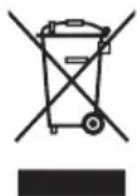
The represented symbol on the product or package means the product shall not be treated as domestic waste. Hand over the product to the specified location for recycling electric and electronic equipment. Prevent negative impacts on human health and the environment by properly recycling your product.
Recycling contributes to preserving natural resources. For more information on the recycling of this product, refer to your local authority, domestic waste processing organization or store, where you purchased the product.
This product complies with EU directive requirements on electromagnetic compatibility and electrical safety.
08/05

The instruction manual is available at website www.ecg.cz.
Changes in text and technical parameters reserved.
www.ecg.cz

- LED 602 PVR
- AUTORÁDIO S USB/SD
- CAR STEREO WITH USB/SD
- BEZPEČNOSTNÍ POKYNY
- VSTUP AUX IN, VÝSTUP RCA OUT
- Externí vstup
- BEZPEČNOSTNÉ POKYNY
- Externý vstup
- SAFETY INSTRUCTIONS
- Read carefully and keep for future use!
- INSTALLATION
- Pre-installation warning
- Installation instructions:
- Remove the old device from the dashboard
- Mark the polarity of the speaker wires
- Warning!
- Front assembly according to the DIN standard (Method A)
- Back assembly according to the DIN standard (Method B)
- WIRING DIAGRAM
- Connector A
- Connector B
- Speaker wiring notes
- BASIC CONTROLS
- Power On/Off
- Mode option
- Loudness
- Mute
- Volume
- Bass
- Treble
- Balance left-right
- Fade front-rear
- Equalizer
- Beep
- Volume pre-set
- Clock
- CONTROLLING THE STEREO
- Radio bandwidth selection
- Tune / Scan
- Switching between stereo and mono reception
- Storing pre-set stations
- Auto-store / scanning through pre-sets
- A: Auto-scan and store
- Local stations
- Receiver Reset
- RDS
- AF - Alternative Frequency
- TA - Traffic Announcement
- PTY - Program Type
- RDS-EON controls
- USB/SD
- Attention:
- MP3/WMA playback from USB/SD
- Playback mode
- Track/folder search
- ID3
- Play/pause
- INTRO
- REPEAT
- RANDOM
- Move forward one directory
- Move back one directory
- AUX IN, RCA OUT
- Auxiliary input
- RCA output
- TROUBLESHOOTING
- TECHNICAL SPECIFICATIONS
- USE AND DISPOSAL OF WASTE
- DISPOSAL OF PRODUCTS AT THE END OF LIFETIME
- www.ecg.cz
Brand : ECG
Model : CD 111 USB
Category : Car radio