
5130 3000VA 2U - Uninterruptible power supply EATON - Free user manual and instructions
Find the device manual for free 5130 3000VA 2U EATON in PDF.


| Product Type | Uninterruptible Power Supply (UPS) |
| Model | Eaton 5130 3000VA 2U |
| Power Rating | 3000 VA / 2700 W |
| Input Voltage | 120 V (adjustable to 100/127 V) or 230 V (adjustable to 200/208/220/240 V) depending on model |
| Output Voltage (on battery) | 120 V (+6/-10%) for low-voltage; 230 V (+6/-10%) for high-voltage; adjustable via configuration tool |
| Frequency | 50/60 Hz ±0.1% (auto-sensing) |
| Dimensions (W x H x D) | 440 mm x 86 mm x 634 mm (17.3" x 3.4" x 25.0") |
| Weight | 35.3 kg (77.9 lb) |
| Form Factor | 2U rackmount or tower (convertible) |
| Battery Type | Sealed, maintenance-free, valve-regulated, lead-acid |
| Internal Battery Configuration | 6 x 12V, 9 Ah |
| Extended Battery Modules (EBM) | Up to 4 EBMs supported (optional) |
| Hot-Swappable Batteries | Yes, batteries can be replaced without powering down the load |
| Start-on-Battery | Yes, UPS can be powered on without utility power |
| Load Segments (PowerShare) | Yes, programmable outlets for prioritized shutdown |
| Communication Ports | USB, RS-232, and optional communication card slot |
| Remote Power-Off (RPO) / Remote On/Off (ROO) | Yes, via two-position terminal |
| Audible Noise | Less than 40 dBA (normal mode), less than 45 dBA (battery mode, 50 dBA for 3000 VA) |
| Operating Temperature | 0°C to 40°C (32°F to 104°F) |
| Safety Compliance | UL 1778, CSA C22.2 No. 107.1, EN 62040-1-1, IEC 60950-1 |
| EMC Compliance | FCC Part 15 Class A (low-voltage) or Class B (high-voltage), EN 62040-2 |
| Warranty | 2-year limited (extendable to 3 years with online registration) |
| Load Protection Guarantee | Up to $150,000 for connected equipment (US and Canada) |
Frequently Asked Questions - 5130 3000VA 2U EATON
User questions about 5130 3000VA 2U EATON
0 question about this device. Answer the ones you know or ask your own.
Ask a new question about this device
Download the instructions for your Uninterruptible power supply in PDF format for free! Find your manual 5130 3000VA 2U - EATON and take your electronic device back in hand. On this page are published all the documents necessary for the use of your device. 5130 3000VA 2U by EATON.
USER MANUAL 5130 3000VA 2U EATON
Requesting a Declaration of Conformity
Units that are labeled with a CE mark comply with the following harmonized standards and EU directives:
•Harmonized Standards: EN 62040-1-1 and EN 62040-2; IEC 60950-1
• EU Directives: 73/23/EEC, Council Directive on equipment designed for use within certain voltage limits 93/68/EEC, Amending Directive 73/23/EEC 2004/108/EEC, Council Directive relating to electromagnetic compatibility
The EC Declaration of Conformity is available upon request for products with a CE mark. For copies of the EC Declaration of Conformity, contact:
Eaton Power Quality Oy
Koskelontie 13
FIN-02920 Espoo
Finland
Phone: +358-9-452 661
Fax: +358-9-452 665 68
Eaton, Powerware, FERRUPS, and LanSafe are registered trademarks of Eaton Corporation or its subsidiaries and affiliates. Microsoft and Windows are registered trademarks of Microsoft Corporation in the United States and other countries. Phillips is a registered trademark of Phillips Screw Company. National Electrical Code and NEC are registered trademarks of National Fire Protection Association, Inc. Phillips is a registered trademark of Phillips Screw Company. All other trademarks are property of their respective companies.
©Copyright 2008–2010 Eaton Corporation, Raleigh, NC, USA. All rights reserved. No part of this document may be reproduced in any way without the express written approval of Eaton Corporation.
Class A EMC Statements (Low-Voltage Models)
FCC Part 15
NOTE This equipment has been tested and found to comply with the limits for a Class A digital device, pursuant to part 15 of the FCC Rules. These limits are designed to provide reasonable protection against harmful interference when the equipment is operated in a commercial environment. This equipment generates, uses, and can radiate radio frequency energy and, if not installed and used in accordance with the instruction manual, may cause harmful interference to radio communications. Operation of this equipment in a residential area is likely to cause harmful interference in which case the user will be required to correct the interference at his own expense.
EN 62040-2
Some configurations are classified under EN 62040-2 as "Category C2 UPS." For these configurations, the following applies:
WARNING This is a category C2 UPS product. In a residential environment, this product may cause radio interference, in which case the user may be required to take additional measures.
Class B EMC Statements (High-Voltage Models)
FCC Part 15
NOTE This equipment has been tested and found to comply with the limits for a Class B digital device, pursuant to part 15 of the FCC Rules. These limits are designed to provide reasonable protection against harmful interference in a residential installation. This equipment generates, uses and can radiate radio frequency energy and, if not installed and used in accordance with the instructions, may cause harmful interference to radio communications. However, there is no guarantee that interference will not occur in a particular installation. If this equipment does cause harmful interference to radio or television reception, which can be determined by turning the equipment off and on, the user is encouraged to try to correct the interference by one or more of the following measures:
- Reorient or relocate the receiving antenna.
- Increase the separation between the equipment and the receiver.
- Connect the equipment into an outlet on a circuit different from that to which the receiver is connected.
- Consult the dealer or an experienced radio/TV technician for help.
Special Symbols
The following are examples of symbols used on the UPS or accessories to alert you to important information:
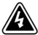
RISK OF ELECTRIC SHOCK - Observe the warning associated with the risk of electric shock symbol.

CAUTION: REFER TO OPERATOR'S MANUAL - Refer to your operator's manual for additional information, such as important operating and maintenance instructions.
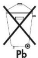
This symbol indicates that you should not discard the UPS or the UPS batteries in the trash. This product contains sealed, lead-acid batteries and must be disposed of properly. For more information, contact your local recycling/reuse or hazardous waste center.
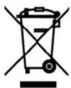
This symbol indicates that you should not discard waste electrical or electronic equipment (WEEE) in the trash. For proper disposal, contact your local recycling/reuse or hazardous waste center.
Table of Contents
1 Introduction ...... 1
2 Safety Warnings 3
3 Installation.... 19
Inspecting the Equipment 19
Checking the Accessory Kit 20
Connecting the UPS Internal Battery 22
UPS Setup 23
Rackmount Setup 23
Required Tools 23
Installing the Rail Kit 24
Tower Setup 25
Installing the UPS 28
RPO and ROO Installation 31
UPS Rear Panels 33
4 Operation 35
Turning the UPS On 35
Starting the UPS on Battery 36
Turning the UPS Off 36
Operating Modes 37
Normal Mode 37
Battery Mode 38
Standby Mode 38
5 Additional UPS Features 39
USB Port 39
Contact Communication Port (optional) 41
Load Segments (PowerShare) 42
Customizing the UPS with the UPS Configuration Tool 43
6 UPS Maintenance 47
UPS and Battery Care 47
Transporting the UPS 47
Storing the UPS and Batteries 48
When to Replace Batteries 48
TABLE OF CONTENTS
Replacing Batteries 48
How to Replace Internal Batteries 49
How to Replace Extended Battery Modules 51
Recycling the Used Battery or UPS 52
7 Specifications 53
8 Troubleshooting 61
Audible Alarms and UPS Conditions 61
Service and Support 63
9 Warranty 65
Two-Year Limited Warranty with Extension to Three-Year Limited Warranty (US and Canada) 65
Load Protection Guarantee (US and Canada) 67
Chapter 1 Introduction
The Eaton® 5130 uninterruptible power system (UPS) protects your sensitive electronic equipment from basic power problems such as power failures, power sags, power surges, brownouts, and line noise.
Power outages can occur when you least expect it and power quality can be erratic. These power problems have the potential to corrupt critical data, destroy unsaved work sessions, and damage hardware — causing hours of lost productivity and expensive repairs.
With the Eaton 5130, you can safely eliminate the effects of power disturbances and guard the integrity of your equipment. The Eaton 5130 was designed for critical applications such as PCs, servers, workstations, and telecommunications equipment.
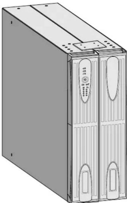
Figure 1 shows the Eaton 5130 UPS with an optional Extended Battery Module (EBM).
natural_image
Illustration of a server rack unit with two front panels and ventilation slots (no text or symbols visible)Figure 1. Eaton 5130 UPS with Optional EBM
Providing outstanding performance and reliability, the Eaton 5130's unique benefits include:
- Hours of extended runtime with up to four EBMs.
- Start-on-battery capability for powering up the UPS even if utility power is not available.
- Hot-swappable batteries that simplify maintenance by allowing you to replace batteries safely without powering down the critical load.
- Shutdown control through the remote power-off (RPO) and remote on/off (ROO) port.
- Two standard communication options with a USB port and an RS-232 serial port.
- Advanced power management for graceful shutdowns and power monitoring.
- Sequential shutdown and load management through separate receptacle groups, called load segments (PowerShare).
- Optional communication cards with enhanced communication capabilities for increased power protection and control.
- Backed by worldwide agency approvals.
Chapter 2 Safety Warnings
IMPORTANT SAFETY INSTRUCTIONS SAVE THESE INSTRUCTIONS
This manual contains important instructions that you should follow during installation and maintenance of the UPS and batteries. Please read all instructions before operating the equipment and save this manual for future reference.
DANGER

This UPS contains LETHAL VOLTAGES. All repairs and service should be performed by AUTHORIZED SERVICE PERSONNEL ONLY. There are NO USER SERVICEABLE PARTS inside the UPS.

WARNING
- This UPS contains its own energy source (batteries). The output receptacles may carry live voltage even when the UPS is not connected to an AC supply.
- For 230V models, the output receptacles may remain electrically live. If the input power source in your application is wired line-to-neutral (as in most European applications), the voltage to the output receptacles is 0V. With line-to-line input wiring, the voltage to the output receptacles is 115V (measured from line-to-ground or line-to-neutral, depending on the UPS wiring).
- Do not remove or unplug the input cord when the UPS is turned on. This removes the safety ground from the UPS and the equipment connected to the UPS.
- To reduce the risk of fire or electric shock, install this UPS in a temperature and humidity controlled, indoor environment, free of conductive contaminants. Ambient temperature must not exceed 40^ C ( 104^ F). Do not operate near water or excessive humidity (95% maximum).
- To comply with international standards and wiring regulations, the total equipment connected to the output of this UPS must not have an earth leakage current greater than 3.5 milliamperes.

CAUTION
- Batteries can present a risk of electrical shock or burn from high short-circuit current. Observe proper precautions. Servicing should be performed by qualified service personnel knowledgeable of batteries and required precautions. Keep unauthorized personnel away from batteries.
- Proper disposal of batteries is required. Refer to your local codes for disposal requirements.
- Never dispose of batteries in a fire. Batteries may explode when exposed to flame.
Chapter 3 Installation
This section explains:
• Equipment inspection
•UPS internal battery connection
- UPS setup and installation, including Extended Battery Modules (EBMs)
- Remote power-off (RPO) or remote on/off (ROO) installation
- UPS rear panels
Inspecting the Equipment
If any equipment has been damaged during shipment, keep the shipping cartons and packing materials for the carrier or place of purchase and file a claim for shipping damage. If you discover damage after acceptance, file a claim for concealed damage.
To file a claim for shipping damage or concealed damage: 1) File with the carrier within 15 days of receipt of the equipment; 2) Send a copy of the damage claim within 15 days to your service representative.

NOTE Check the battery recharge date on the shipping carton label. If the date has passed and the batteries were never recharged, do not use the UPS. Contact your service representative.
Checking the Accessory Kit
Verify that the following additional items are included with the UPS:
Table 1. UPS Accessory Kit
| Item Description | |
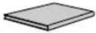 | UPS user's guide or CD |
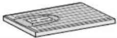 | UPS front cover |
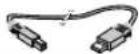 | USB cable |
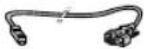 | RS-232 serial cable |
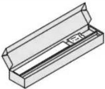 | Rackmounting kit for 19-inch (48 cm) bays |
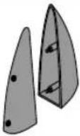 | 2U models only.Two pedestals with screws for tower position |
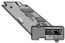 | Optional.Network Management Card |
The high-voltage models include the following additional items:
Table 2. Additional High-Voltage Model Accessory Items
| Item Description | |
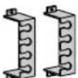 | Two cord-retention brackets |
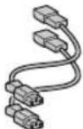 | Two equipment power cords |
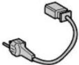 | 2500–3000 VA models only.Power cord |
If you ordered an optional EBM, verify that the following items are included with the EBM:
Table 3. EBM Accessory Items
| Item Description | |
 | EBM user's guide |
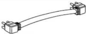 | EBM cable |
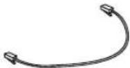 | EBM communication cable |
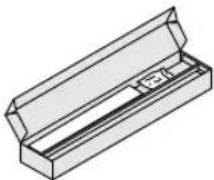 | Rackmounting kit for 19-inch (48 cm) bays |
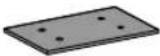 | Joining bracket and screws for tower position |
Connecting the UPS Internal Battery
To ensure proper battery operation:
- Verify that the UPS is off and unplugged.
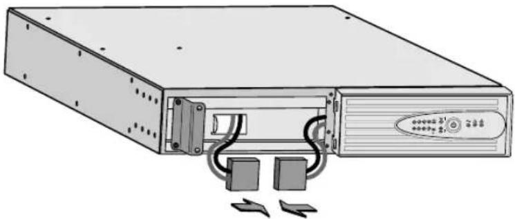
- Connect the internal battery connectors by firmly pressing the connectors together (see Figure 2).
natural_image
Illustration of a server rack with two connectors and a control panel (no text or symbols)Figure 2. Connecting the Internal Battery Connectors

NOTE A small amount of arcing may occur when connecting the batteries. This is normal and does not damage the unit or present any safety concern.
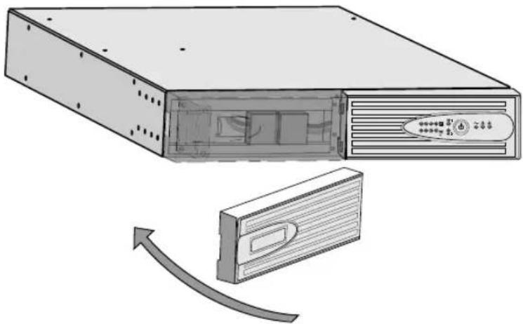
- Install the UPS front cover and snap into place (see Figure 3).
natural_image
Illustration of a computer drive chassis with an arrow indicating a loading or transmission process (no text or symbols present)Figure 3. Installing the UPS Front Cover
- Continue to the following section, "UPS Setup."
UPS Setup
The Eaton 5130 UPS is designed for flexible configurations and can be installed in a rack or as a standalone cabinet.
If you are installing the UPS in a rack, continue to the following section, "Rackmount Setup;" otherwise, continue to "Tower Setup" on page 25.
Rackmount Setup
The rail kit can be mounted in 19-inch panel (48 cm) racks from 24 to 30 inches (61 to 76 cm) deep and includes:
- Left and right sliding rail assemblies
•(12) M5 washers
•(12) M512 mm Phillips -head screws
• (8) M45 mm Phillips-head screws
•(2) mounting brackets with handles
Required Tools
To assemble the components, a #2 Phillips screwdriver may be needed.
Installing the Rail Kit
CAUTION

The UPS and EBM are heavy (see page 54). A minimum of two people are required to lift the cabinets into the rack.

NOTE Mounting rails are required for each UPS and EBM cabinet. If mounting rails are not already installed in your rack, contact your local distributor to order rail kits.
To install the rail kit:
- Adjust the rail size for the depth of your rack.
- Select the proper holes in the rail for positioning the UPS in the desired location in the rack.
- Using two M5 washers and two M5 screws, attach the rail to the rear of the rack (see Figure 4).
- Secure the rail to the front of the rack with two M5 washers and two M5 screws.
- Repeat Steps 3 and 4 for the other rail.
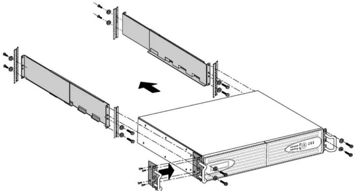
Figure 4. Installing the Rail Kit
-
Place the UPS on a flat, stable surface with the front of the UPS facing you.
-
Attach the supplied mounting brackets to the cabinet and secure with four M4 screws on each side (see Figure 4).
-
If installing optional EBMs, repeat Steps 1 and 7 for each cabinet.

NOTE The UPS and EBMs MUST be installed at the bottom of the rack. If placed in a rack with existing equipment, the rack must be reconfigured to allow the UPS installation at the bottom of the rack.
NOTE The EBMs must be installed below the UPS.
-
Slide the UPS and any optional EBMs into the rack.
-
Secure the front of the cabinet to the rack using two M5 washers and two M5 screws on each side (see Figure 4).
-
Continue to "Installing the UPS" on page 28.
Tower Setup
The setup varies depending on the size of the cabinet you are installing:
- Carefully position the cabinet upright with the air vents at the top (see Figure 5).
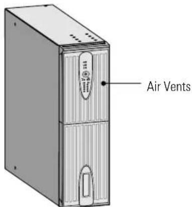
Figure 5. 3U Cabinet
- For one 2U cabinet, the pedestals must be installed. Continue to Step 3.
For one 3U cabinet, continue to "Installing the UPS" on page 28.
For two or more cabinets, the joining brackets must be installed. Skip to Step 5.
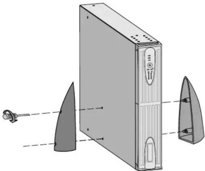
- Align the pedestals with the screw holes on the sides of the UPS cabinet. Secure the pedestals with the captive screws.
natural_image
Diagram of a desktop computer tower with visible drive and lens components (no text or labels)Figure 6. Installing UPS Pedestals (for One 2U Cabinet)
-
Continue to the following section, "Installing the UPS."
-
Align each joining bracket with the adjacent cabinet screw holes and secure with the supplied screws (see Figure 7).

NOTE Joining brackets are required for installations with two or more cabinets.
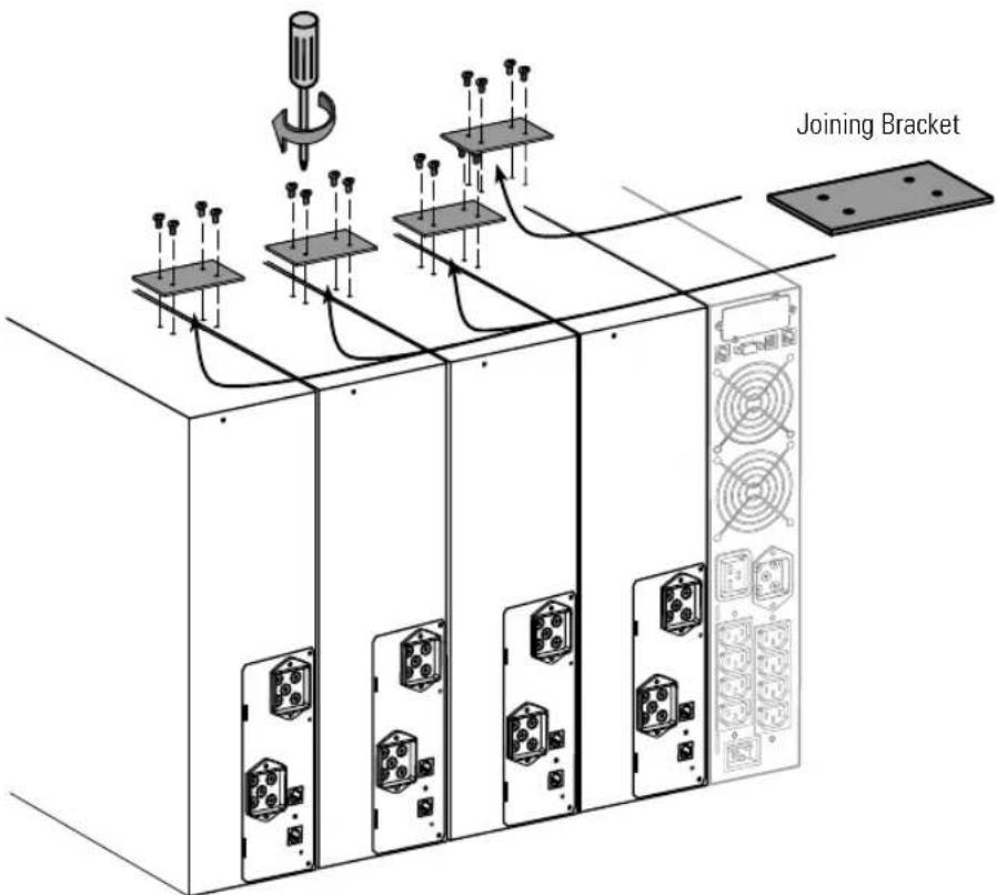
Figure 7. Installing the Joining Brackets
-
If installing additional EBMs, repeat Step 5 for each cabinet.
-
Continue to the following section, "Installing the UPS."
Installing the UPS

NOTE Do not make unauthorized changes to the UPS or accessories; otherwise, damage may occur to your equipment and void your warranty.
See "UPS Rear Panels" on page 33 for the rear panel of each model.
To install the UPS and optional EBMs:
-
If installing an optional EBM, continue to Step 2; otherwise, continue to Step 3.
-
Plug the EBM cable into the battery connector. Plug the EBM communication cable into the RJ-11 port. See Figure 8.
Up to four EBMs may be connected to the UPS.
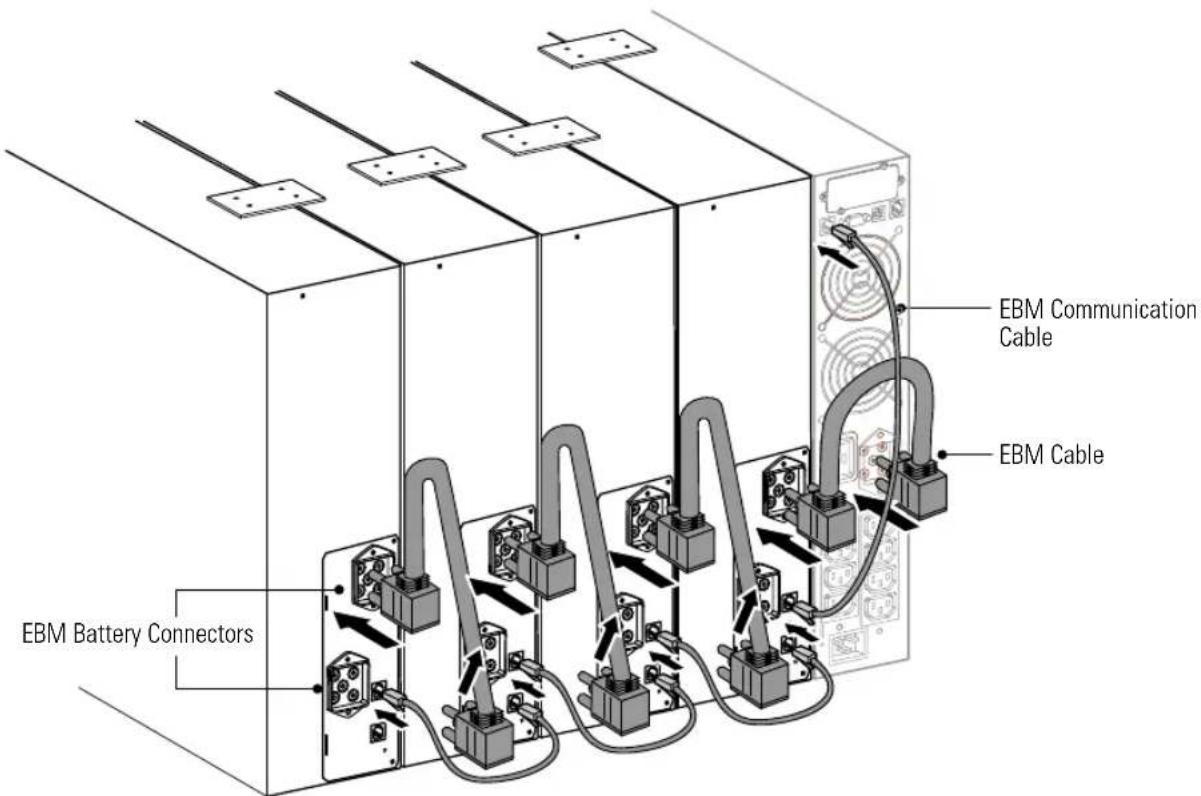
Figure 8. UPS Installation with Four EBMs
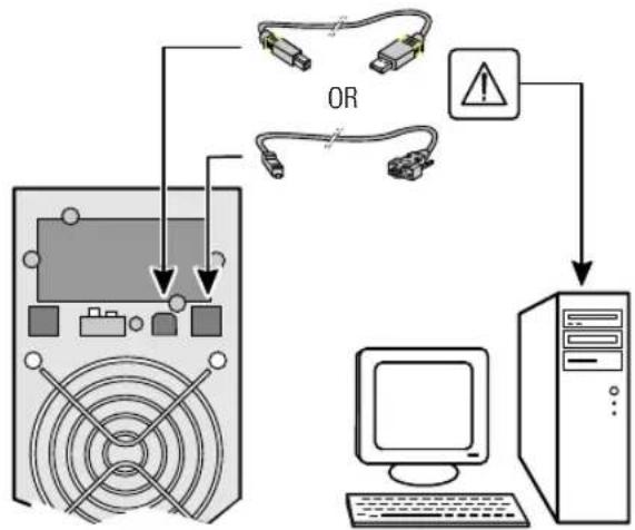
- If you plan to install power management software, connect your computer to the USB port or RS-232 communication port using the supplied communication cable.
flowchart
graph TD
    A["Monitor"] -->|OR| B["Computer"]
    B --> C["Server"]
    C --> D["Hardware"]
    D --> E["Warning Indicator"]
    E --> A
    style A fill:#f9f,stroke:#333
    style B fill:#ccf,stroke:#333
    style C fill:#cfc,stroke:#333
    style D fill:#fcc,stroke:#333
    style E fill:#ffc,stroke:#333
Figure 9. Installing a Communication Cable
- For rackmount installations only. If your rack has conductors for grounding or bonding of ungrounded metal parts, connect the ground cable (not included) to the ground bonding screw. See "UPS Rear Panels" on page 33.

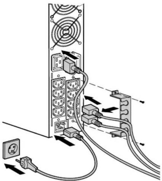
- Plug the equipment to be protected into the appropriate UPS output receptacles (see page 42 for more information on load segments). See Figure 10.
NOTE DO NOT protect laser printers with the UPS because of the exceptionally high power requirements of the heating elements.
- High-voltage models only. Install the cord-retention bracket to secure the cords and provide strain relief (see Figure 10).
Plug a 10A power cord into the input connector on the UPS rear panel (16A power cord supplied for 2500–3000 VA models).
natural_image
Diagram of a server rack connected to multiple switches and cables, showing power connections (no text or labels)Figure 10. Installing the Power and Equipment Cords (High-voltage only)
-
If you are installing a remote power-off or a remote on/off switch, see the following section, "RPO and ROO Installation," to install the switch before powering on the UPS.
-
Continue to "Turning the UPS On" on page 35.
RPO and ROO Installation
The Eaton 5130 includes a two-position terminal (see Figure 11) that can be either left closed or configured one of two ways:
- RPO: Allows a remote contact to be used to disconnect all equipment connected to the UPS. Restarting the UPS requires manual intervention.
- ROO: Allows remote action of the (1) button to shut down the UPS.
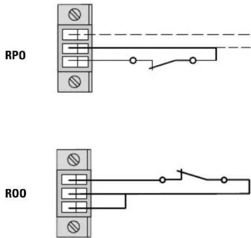
Figure 11. RPO/ROO Connection

WARNING
The RPO/ROO circuit is an IEC 60950 safety extra low voltage (SELV) circuit. This circuit must be separated from any hazardous voltage circuits by reinforced insulation.
To install the RPO or ROO switch:
- Verify that the UPS is off and unplugged.
- Unscrew and remove the RPO/ROO connector from the RPO/ROO port on the UPS rear panel.
- Refer to the following table to plan the RPO or ROO behavior:
| Contact RPO ROO* | ||
| Open | UPS shuts down, the indicator illuminates | UPS shuts down |
| Closed Normal operationTo return to normal operation, deactivate the remote external contact and restart the UPS by pressing the button | UPS starts up (UPS connected to AC power and AC power is available) | |
NOTE The local ⏻ button overrides the R00 function.
- Connect isolated, normally-closed, dry contacts (rated to handle 60 Vdc maximum, 30 Vac RMS maximum, and 20 mA maximum). Use stranded, non-shielded wiring, size 0.75 mm ^2 –0.5 mm ^2 (18–20 AWG).
- Reinstall the RPO/ROO connector to the RPO/ROO port.
- Verify that the externally-connected RPO switch is not activated to enable power to the UPS output receptacles.
- Plug the UPS power cord into a power outlet.
- Press and hold the ⏻ button until you hear the UPS beep (approximately one second).
- Activate the external RPO or ROO switch to test the function. Verify the status change on the UPS front panel.
- RPO only. De-activate the external RPO switch and restart the UPS.
UPS Rear Panels
This section shows the rear panels of the Eaton 5130 models.
![USB Port RS-232 Port EBM Battery Connector Receptacles [(6) 5-15R - 1000–1500 VA (8) 5-15/5-20R - 2200 VA] Communication Bay EBM RJ-11 Connector Site Fault Indicator RPO/ROO Connector Ground Bonding Screw Power Cord (15A, 5-15 plug - 1000–1500 VA 20A, 5-20 plug - 2200 VA)](/content/2026/05/845010/images/f3f680024ca719df4182ad39f3dc913bdb43562307b6e0ce21d8a6cabb965ec8.jpg)
Figure 12. 1000–2200 VA, Low-Voltage Rear Panel (1000–1500 VA Rear Panel Shown)
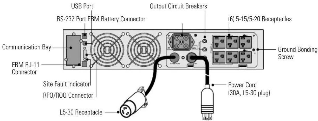
Figure 13. 3000 VA, Low-Voltage Rear Panel
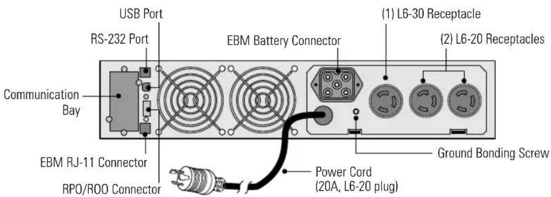
Figure 14. 208V Rear Panel
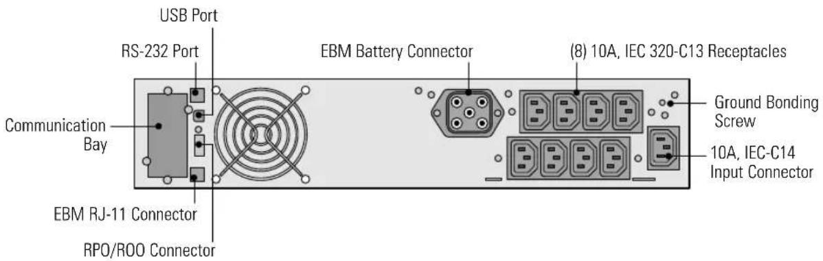
Figure 15. 1000–1750 VA, High-Voltage Rear Panel
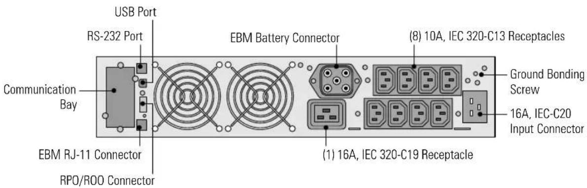
Figure 16. 2500–3000 VA, High-Voltage Rear Panel
Chapter 4 Operation
This section describes:
- Turning the UPS on and off
- Starting the UPS on battery
- Initiating the self-test
- Operating modes
Turning the UPS On
To turn the UPS on:
- Plug the UPS power cord into a power outlet.
The □ bar graph indicators illuminate, indicating the UPS is in Standby mode.
- Press and hold the ⏻ button until you hear the UPS beep (approximately two seconds).
The alarm beeps once and all front panel indicators flash briefly. The ⏻ button and the ∼ illuminate. Conditions permitting, the UPS runs a battery test and the ⚡ bar graph indicators cycle through. The load segment indicators (W1 and W2) show that power is available to the output receptacles.
The % bar graph indicators display the percentage of load being applied to the UPS. The UPS is now in Normal mode and supplying power to your equipment.
To change the factory-set defaults, see "Customizing the UPS with the UPS Configuration Tool" on page 43.
- If the △ indicator illuminates, see Table 17 on page 62.

NOTE The batteries charge to 90% capacity in approximately 3 hours. However, it is recommended that the batteries charge for 24 hours after installation or long-term storage.
NOTE If more than two EBMs are installed, an external battery charger is recommended for faster recharge times.
Starting the UPS on Battery

NOTE Before using this feature, the UPS must have been powered by utility power at least once.
To turn on the UPS without using utility power, press and hold the ⏻ button for two seconds. The UPS starts up in Battery mode and supplies battery power to your equipment.
Turning the UPS Off

NOTE Pressing the ⏻ button while the UPS is in Battery mode causes the UPS to shut down immediately.
To turn off the UPS:
- Prepare your equipment for shutdown.
- Press and hold the ⏻ button for two seconds. The UPS transfers to Standby mode (if utility power is available) and removes power from your equipment.
- Unplug the UPS.
If you do not unplug the UPS, it remains in Standby mode.
Operating Modes
The Eaton 5130 front panel indicates the UPS status through the UPS indicators. Figure 17 shows the UPS front panel indicators and controls.
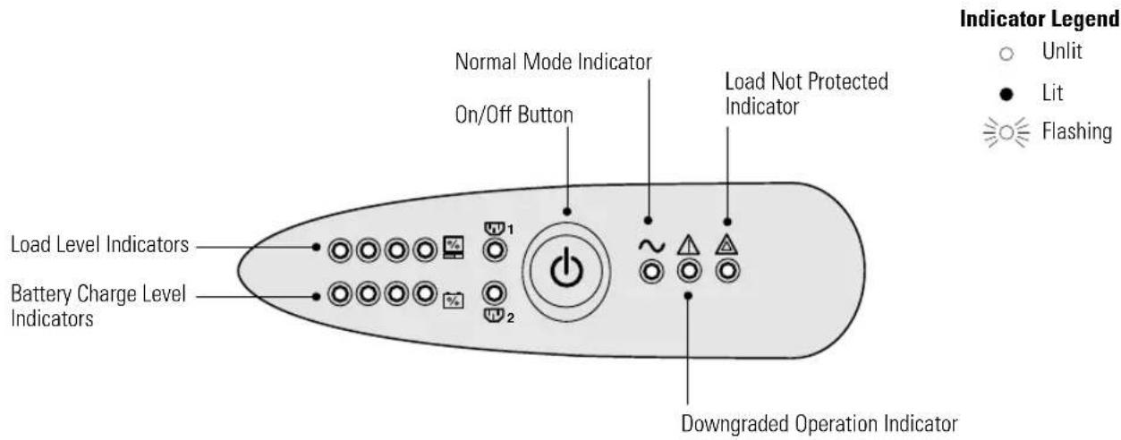
Figure 17. UPS Front Panel
Normal Mode
During Normal mode, the button and the \~ indicator illuminate and the front panel displays the percentage of UPS load capacity being used by the protected equipment (see Figure 18). The UPS monitors and charges the batteries as needed and provides power protection to your equipment.
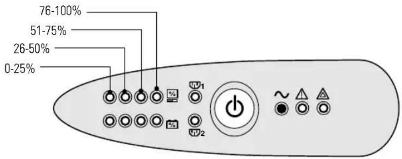
Figure 18. Load Level Indicators
When all of the bar graph indicators and the indicator are illuminated, power requirements exceed UPS capacity; see page 62 for more information.
Battery Mode
When the UPS is operating during a power outage, the alarm beeps once every 10 seconds and the ⏻ button, the ∼, and △ indicators are on. The □ bar graph indicators show the level of remaining battery power.
When utility power returns, the UPS transfers to Normal mode operation while the battery recharges.
If battery capacity becomes low while in Battery mode, the alarm beeps every three seconds. Immediately complete and save your work to prevent data loss and similar difficulties.
When utility power is restored after the UPS shuts down, the UPS automatically restarts.
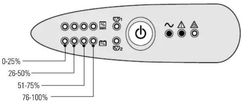
Figure 19. Battery Charge Level Indicators
Standby Mode
When the UPS is turned off and remains plugged into a power outlet, the UPS is in Standby mode. The % bar graph indicators are on and all other indicators are off, indicating that power is not available from the UPS output receptacles. The battery recharges when necessary.

NOTE For 230V models, the output receptacles may remain electrically live (up to 115V). Unplug the UPS to ensure power is not available to the output receptacles.
Chapter 5 Additional UPS Features
This section describes:
- USB port
•RS-232 communication port - Communication card
- Load segments (PowerShare)
The Eaton 5130 UPS includes a USB port, a RS-232 communication port, and a bay for an optional communication card. The USB and RS-232 ports cannot operate simultaneously.
USB Port
The UPS can communicate with a USB-compliant computer using LanSafe® Power Management Software or other HID-compliant power management software compatible with Microsoft® Windows® 2000 and XP operating systems that support HID devices.

NOTE The latest versions of the LanSafe Power Management Software and the USB firmware are available at www.eaton.com/powerquality.
To establish communication between the UPS and a computer:
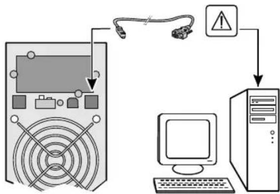
- The USB port is hot-pluggable. Connect the USB cable to the USB port on the UPS rear panel (see Figure 20).
Connect the other end of the USB cable to the USB port on your computer.
flowchart
graph TD
    A["Server"] -->|Signal| B["Computer"]
    B --> C["Hardware"]
    C --> D["Warning symbol"]
    D --> A
Figure 20. The USB Port
- Install the LanSafe Power Management Software and USB drivers according to the instructions provided at www.eaton.com/powerquality.
Contact Communication Port (optional)
When a signal is activated, the contact is closed between the common (Pin 4) and the pin for the corresponding signal.
Contact characteristics (optocoupler):
•Voltage: 48 V DC max
•Current: 25 mA max
•Power: 1.2W
Figure 21 identifies the cable pins and Table 4 describes the pin functions.
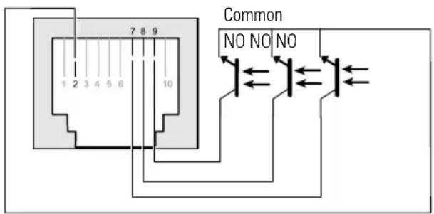
NOTE Normally-open (NO)
Figure 21. Communication Port
Table 4. Communication Port Pin Assignment
| Pin Number Function |
| 1, 3, 4, 5, 6, 10 Not used |
| 2 Common |
| 7 Low Battery |
| 8 Operation on battery power |
| 9 UPS ON, equipment supplied |
Load Segments (PowerShare)
Each UPS has programmable outlets as shown in Figure 22 through Figure 24. During a power outage, you can keep key pieces of equipment running while you turn off other equipment. It is preferable to connect the non-priority loads to the programmable receptacles, ☐1 and ☐2. This feature allows you to save battery power. See your power management software manual for details (refer to www.eaton.com/powerquality for the latest information).

NOTE If power management software is not used, the individual load segments cannot be controlled.
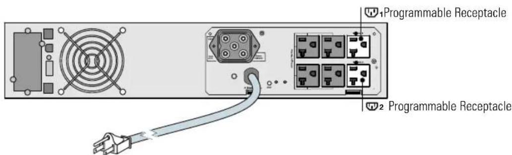
Figure 22. Low-Voltage Load Segments
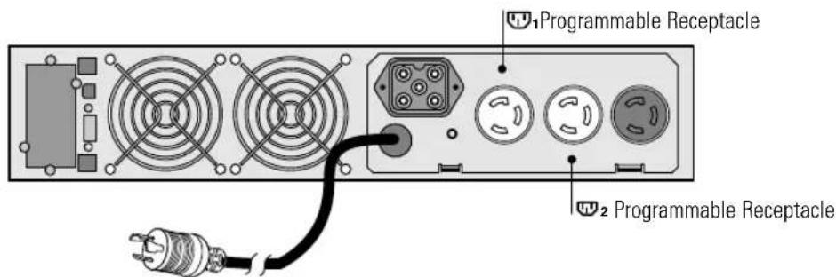
Figure 23. 208V Load Segments
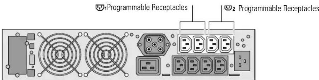
Figure 24. High-Voltage Load Segments
Customizing the UPS with the UPS Configuration Tool
To customize the UPS settings:
-
Download the UPS Configuration tool from www.eaton.com/powerquality.
-
Follow the on-screen instructions for the Eaton 5130.
It is possible to modify the settings listed below (detailed comments are available in the UPS Configuration tool).
Table 5. Main Output Options
| Function Factory Setting Other Available Settings | |
| Low-Voltage Models. Output voltage on battery power | 120 Vac 100/120/127 Vac |
| High-Voltage Models. Output voltage on battery power | 230 Vac 200/208/220/240 Vac |
| PW5130G3000-XL2U Models. Output voltage on battery power | 208V — |
| All Models. Overload alarm threshold | 105% 30/50/70% |
Table 6. Voltage Threshold Options
| Low-Voltage Model Function | Factory Setting | Other Available Settings |
| High threshold for transfer to battery | 151 Vac ±3% 141–153 Vac | |
| Low threshold for transfer to battery | 89 Vac ±3% 89–94 Vac | |
| Fader activation threshold | 132 Vac ±3% 127–138 Vac | |
| Booster activation threshold | 102 Vac ±3% 92–108 Vac | |
| Maximum input-voltage range | Disabled Enabled | 1 |
| High-Voltage Model Function Factory Setting Other Available Settings | ||
| High threshold for transfer to battery | 294 Vac 271–294 Vac | |
| Low threshold for transfer to battery | 160 Vac 160–180 Vac | |
| Fader activation threshold | 265 Vac 244–265 Vac | |
| Booster activation threshold | 184 Vac 184–207 Vac | |
| Maximum input-voltage range | Disabled Enabled | 2 |
| ^1 Low threshold for transfer to battery is 70V. ^2 Low threshold for transfer to battery is 150V. | ||
| PW5130G3000-XL2U Function Factory Setting Other Available Settings | ||
| High threshold for transfer to battery | 263 Vac — | |
| Low threshold for transfer to battery | 160 Vac — | |
| Fader activation threshold | 229 Vac — | |
| Booster activation threshold | 177 Vac — | |
| Maximum input-voltage range | Disabled Enabled | 2 |
^2 Low threshold for transfer to battery is 150V.
Table 7. UPS Sensitivity Options
| Function | Factory Setting Other Available Settings |
| UPS-sensitivity level | Normal High or low |
Table 8. UPS On/Off Options
| Function | Factory Setting Other Available Settings |
| Automatic start | Enabled Disabled |
| Cold start | Enabled Disabled |
| Forced shutdown | Enabled Disabled |
| Energy-savings mode | Disabled Enabled |
| UPS ON/OFF controlled by software | Enabled Disabled |
| Battery level before restart | 0% 0–100% |
Table 9. Battery Options
| Function | Factory Setting Other Available Settings | |
| Battery-test intervals | Weekly No test / daily test / monthly test | |
| Low-battery warning | 20% 0–100% | |
| Battery protection against deep discharge | Enabled Disabled | |
| Audio alarm | Enabled Disabled | |
| Additional battery module | Automatic detection of number of battery modules | For specific batteries, 25–81 Ah |
ADDITIONAL UPS FEATURES
Chapter 6 UPS Maintenance
This section explains how to:
•Care for the UPS and batteries
- Transport the UPS
- Store the UPS and batteries
-Replace the batteries
- Test new batteries
•Recycle used batteries or UPS
UPS and Battery Care
For the best preventive maintenance, keep the area around the UPS clean and dust-free. If the atmosphere is very dusty, clean the outside of the system with a vacuum cleaner.
For full battery life, keep the UPS at an ambient temperature of 25^ C ( 77^ F).

NOTE The batteries in the UPS are rated for a 3–5 year service life. The length of service life varies, depending on the frequency of usage and ambient temperature. Batteries used beyond expected service life will often have severely reduced runtimes. Replace batteries at least every 5 years to keep units running at peak efficiency.
Transporting the UPS

NOTE The internal UPS batteries MUST be disconnected.
If the UPS requires any type of transportation:
- Verify that the UPS is unplugged and turned off.
- Disconnect the UPS internal battery connector using the steps in "Connecting the UPS Internal Battery" on page 22 in reverse order.
Storing the UPS and Batteries
If you store the UPS for a long period, recharge the battery every 6 months by plugging the UPS into a power outlet. The batteries charge to 90% capacity in approximately 3 hours. However, it is recommended that the batteries charge for 24 hours after long-term storage.
Check the battery recharge date on the shipping carton label. If the date has expired and the batteries were never recharged, do not use the UPS. Contact your service representative.
When to Replace Batteries
If all four bar graph indicators flash and either the or △ ▲ indicators are on, the batteries may need replacing. Contact your service representative to order new batteries.
Replacing Batteries

NOTE DO NOT DISCONNECT the batteries while the UPS is in Battery mode.
With the hot-swappable battery feature, UPS batteries can be replaced easily without turning the UPS off or disconnecting the load.
If you prefer to remove input power to change the batteries, see "Turning the UPS Off" on page 36.
Consider all warnings, cautions, and notes before replacing batteries.

WARNING
- Batteries can present a risk of electrical shock or burn from high short-circuit current. The following precautions should be observed: 1) Remove watches, rings, or other metal objects; 2) Use tools with insulated handles; 3) Do not lay tools or metal parts on top of batteries.
- ELECTRIC ENERGY HAZARD. Do not attempt to alter any battery wiring or connectors. Attempting to alter wiring can cause injury.
How to Replace Internal Batteries
CAUTION

- Pull the battery out onto a flat, stable surface. The battery is unsupported when you pull it out of the UPS.
• To ensure safety and high performance, use only batteries supplied by Eaton.
To replace the UPS internal batteries:
- Remove the UPS front cover. Press the button on the left side of the cover and then pull the left side (see Figure 25).
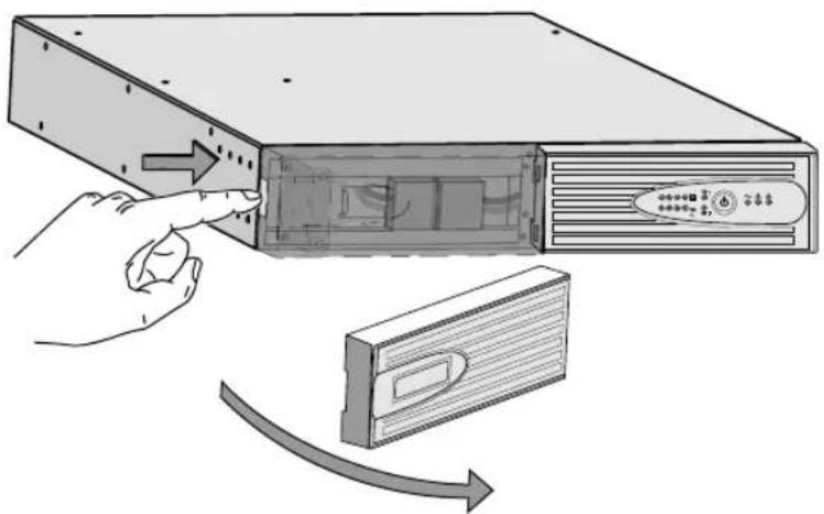
Figure 25. Removing the UPS Front Cover
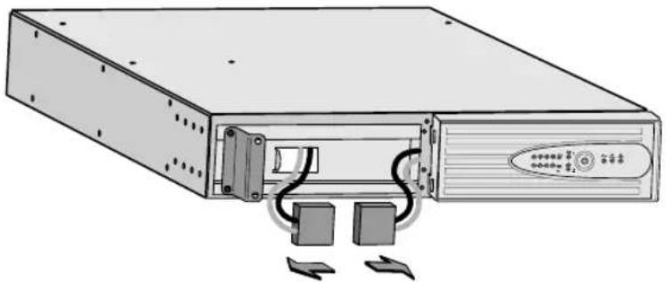
- Disconnect the internal battery connectors (see Figure 26).
natural_image
Illustration of a server rack with two ports and cables, no text or symbols presentFigure 26. Disconnecting the Internal Battery Connectors
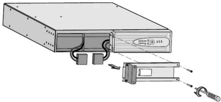
- Unscrew and remove the metal battery cover (see Figure 27).
natural_image
Diagram of an electronic device showing a front panel, internal components, and external wiring (no text or symbols present)Figure 27. Removing the Battery Cover
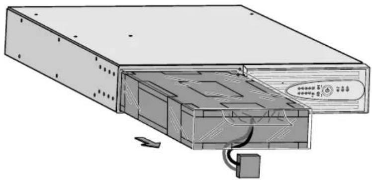
- Pull the battery block out onto a flat, stable surface (see Figure 28).
See "Recycling the Used Battery or UPS" on page 52 for proper disposal.
natural_image
Technical line drawing of an internal electronic device showing casing, drive, and cable (no text or symbols)Figure 28. Removing the Battery Block
- Install the new batteries in the reverse order of removal.
- Replace the metal battery cover.
- Replace the UPS front cover.
How to Replace Extended Battery Modules
To replace the Extended Battery Modules (EBMs):
- Unplug the EBM cable from the UPS.
If additional EBMs are installed, unplug the EBM cable from the battery connector on each EBM.
-
Unplug the EBM communication cable from the RJ-11 port. Repeat for each EBM.
-
For tower models only. Remove the joining bracket between cabinets.
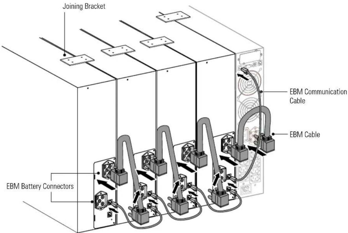
Figure 29. EBM Connections (230V Tower Model Shown)
- Replace the EBM. See "Recycling the Used Battery or UPS" on page 52 for proper disposal.
- For tower models only. Install the joining bracket between cabinets.
- Plug the new EBM into the UPS as shown in Figure 29.
For additional EBMs, plug the EBM cable into the battery connector on the adjacent EBM.
- Plug the EBM communication cable into the RJ-11 port. Repeat for each EBM.
Recycling the Used Battery or UPS
Contact your local recycling or hazardous waste center for information on proper disposal of the used battery or UPS.

WARNING
- Do not dispose of the battery or batteries in a fire. Batteries may explode. Proper disposal of batteries is required. Refer to your local codes for disposal requirements.
- Do not open or mutilate the battery or batteries. Released electrolyte is harmful to the skin and eyes. It may be toxic.
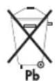
CAUTION
Do not discard the UPS or the UPS batteries in the trash. This product contains sealed, lead-acid batteries and must be disposed of properly. For more information, contact your local recycling/reuse or hazardous waste center.
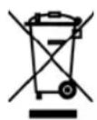
CAUTION
Do not discard waste electrical or electronic equipment (WEEE) in the trash. For proper disposal, contact your local recycling/reuse or hazardous waste center.
Chapter 7 Specifications
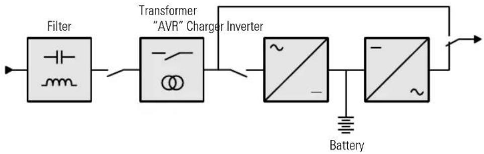
flowchart
graph LR
    A["Filter"] --> B["Transformer "AVR" Charger Inverter"]
    B --> C["Battery"]
    B --> D["~"]
    B --> E["~"]
Figure 30. Block Diagram
Table 10. Low-Voltage Model Specifications
| Model Number | Power Levels (Rated at Nominal Inputs) | AC Input Output on Battery Power | ||||
| Nominal Voltage | Voltage Range1 | Frequency Range2 | Voltage3 | Frequency | ||
| PW5130L1000-XL2U 1000 VA, 1000W | 120V 89–151V | 47–70 Hz (50 Hz system), 56.5–70 Hz (60 Hz system) | 120V (+6/-10%) | 50/60 Hz ±0.1% | ||
| PW5130L1500-XL2U 1500 VA, 1400W | ||||||
| PW5130L2200-XL2U 2200 VA, 1920W | ||||||
| PW5130L3000-XL2U | 2880 VA, 2700W | |||||
| PW5130L3000-XL3U | ||||||
^1 The high and low thresholds can be adjusted using the UPS Configuration tool (see page 43).
^2 Up to 40 Hz in low-sensitivity mode (programmable using the UPS Configuration tool).
^3 Adjustable to 100V (10% derating of output power) 120/127V.
Table 11. High-Voltage Model Specifications
| Model Number | Power Levels (Rated at Nominal Inputs) | AC Input Output on Battery Power | ||||
| Nominal Voltage | Voltage Range1 | Frequency Range2 | Voltage3 | Frequency | ||
| PW5130i1250-XL2U 1250 VA, 1150W | 220–240V 160–294V | 47–70 Hz (50 Hz system), 56.5–70 Hz (60 Hz system) | 230V (+6/-10%) | 50/60 Hz ±0.1% | ||
| PW5130i1750-XL2U 1750 VA, 1600W | ||||||
| PW5130i2500-XL2U 2500 VA, 2250W | ||||||
| PW5130i3000-XL2U | 3000 VA, 2700W | |||||
| PW5130i3000-XL3U | ||||||
| PW5130G3000-XL2U 3000 VA, 2700W 208V 160–263V | 208V (+6/-10%) | |||||
^1 The high and low thresholds can be adjusted using the UPS Configuration tool (see page 43).
^2 Up to 40 Hz in low-sensitivity mode (programmable using the UPS Configuration tool).
^3 Adjustable to 100V (10% derating of output power) 120/127V.
Table 12. Weights and Dimensions
| Low-Voltage Model Number Dimensions (WxHxD) Weight | ||
| PW5130L1000-XL2U | 44086509 mm | 24.6 kg (54.3 lb) |
| PW5130L1500-XL2U 26.3 kg (58.0 lb) | 17.3"3.4"20.0" | |
| PW5130L2200-XL2U | 44086634 mm | 34.7 kg (76.4 lb) |
| PW5130L3000-XL2U 35.3 kg (77.9 lb) | 17.3"3.4"25.0" | |
| PW5130L3000-XL3U | 440131484 mm17.3"5.2"19.0" | 33.8 kg (75.5 lb) |
| High-Voltage Model Number Dimensions (WxHxD) Weight | ||
| PW5130i1250-XL2U | 44086509 mm | 24.3 kg (53.6 lb) |
| PW5130i1750-XL2U | 17.3"3.4"20.0" | |
| PW5130i2500-XL2U | 44086634 mm | 33.8 kg (74.5 lb) |
| PW5130i3000-XL2U | 17.3"3.4"25.0" | |
| PW5130G3000-XL2U | 44086634 mm17.3"3.4"25.0" | 35.3 kg (77.9 lb) |
| PW5130i3000-XL3U | 440131484 mm17.3"5.2"19.0" | 34.3 kg (75.6 lb) |
| EBM Model Number Dimensions (WxHxD) Weight | ||
| PW5130N1750-EBM2U | 44086509 mm17.3"3.4"20.0" | 29.1 kg (64.2 lb) |
| PW5130N3000-EBM2U | 44086634 mm17.3"3.4"25.0" | 42.0 kg (92.7 lb) |
| PW5130N3000-EBM3U | 440131484 mm17.3"5.2"19.0" | 39.9 kg (88.0 lb) |
Table 13. Power Connections
| Model Input Connection Output Receptacles | |
| PW5130L1000-XL2U | 8 ft, 15A, 5-15P power cord (6) 5-15R |
| PW5130L1500-XL2U | |
| PW5130L2200-XL2U 8 ft, 20A, L5-20P power cord (8) 5-15/5-20R | |
| PW5130L3000-XL2U | 6 ft, 30A, L5-30P power cord (6) 5-15/5-20R; (1) L5-30R |
| PW5130L3000-XL3U | |
| PW5130i1250-XL2U | 10A, IEC-C14 input connector (8) 10A, IEC 320-C13 |
| PW5130i1750-XL2U | |
| PW5130i2500-XL2U | 16A, IEC-C20 input connector (8) 10A, IEC 320-C13; (1) 16A, IEC 320-C19 |
| PW5130i3000-XL2U | |
| PW5130i3000-XL3U | |
| PW5130G3000-XL2U 6 ft, 20A, L6-20P power cord (1) L6-30R; (2) L6-20R | |
Table 14. Environmental and Safety
| Low Voltage Models High Voltage Models | ||
| Operating Temperature 0°C to 40°C (32°F to 104°F) | ||
| Storage Temperature -25°C to 40°C (-13°F to 104°F) | ||
| Relative Humidity Storage: 10–95% noncondensing | ||
| Operating: 20–95% noncondensing | ||
| Audible Noise Less than 40 dBA Normal mode, typical loadLess than 45 dBA (50 dBA for 3000 VA) Battery mode | ||
| Surge Suppression ANSI C62.41 Category B, IEC 61000-4-5 | ||
| Safety Conformance UL 1778, UL 497A;CSA C22.2, No. 107.1;NOM-019-SCFI | UL 1778, UL 497A (data line only);CSA C22.2, No. 107.1;EN 62040-1-1, IEC 60950-1, IEC 50091-1-1 | |
| Agency Markings cULus, cUL cTUVus, CE | ||
| EMC FCC Part 15 Class A EN 62040-2 C1, AS 62040-2 C1,FCC Part 15 Class B | ||
Table 15. Battery
| UPS Configuration 1000/1250 VA: (4) 12V, 7.2 Ah internal batteries | |
| 1500/1750 VA: (4) 12V, 9 Ah internal batteries | |
| 2200/2500 VA: (6) 12V, 7.2 Ah internal batteries | |
| 3000 VA: (6) 12V, 9 Ah internal batteries | |
| EBM Configuration PW5130N1750-EBM2U: 48 Vdc, (2 stings of 4) 12V, 9 Ah batteries | |
| PW5130N3000-EBM2U and PW5130N3000-EBM3U: 72 Vdc, (2 strings of 6) 12V, 9 Ah batteries | |
| Type Sealed, maintenance-free, valve-regulated, lead-acid | |
Table 16. Battery Runtimes (in minutes)
| Load | UPS Internal Batteries | +1 EBM | +2 EBMs | +3 EBMs | +4 EBMs |
| PW5130L1000-XL2U (with PW5130N1750-EBM2U) | |||||
| 100 VA/70W 112 440 841 1196 1530 | |||||
| 250 VA/175W 59 255 570 725 975 | |||||
| 500 VA/350W 25 125 225 305 422 | |||||
| 750 VA/525W 16 78 140 210 155 | |||||
| 1000 VA/700W 10 56 100 150 192 | |||||
| 1000 VA/1000W 7 36 66 97 128 | |||||
| PW5130L1500-XL2U (with PW5130N1750-EBM2U) | |||||
| 150 VA/105W 90 302 495 710 920 | |||||
| 375 VA/262W 45 150 270 410 530 | |||||
| 750 VA/525W 19 61 121 185 250 | |||||
| 1125 VA/787W 10 45 70 110 150 | |||||
| 1500 VA/1050W 7 32 58 84 111 | |||||
| 1500 VA/1400W 4 22 40 55 77 | |||||
| PW5130L2200-XL2U (with PW5130N3000-EBM2U) | |||||
| 195 VA/136W 119 426 608 1082 1450 | |||||
| 488 VA/341W 55 185 370 639 810 | |||||
| 975 VA/682W 23 105 190 285 370 | |||||
| 1463 VA/1045W 12 56 105 150 220 | |||||
| 1950 VA/1365W 8 38 65 114 152 | |||||
| 1950 VA/1920W 5 27 48 70 97 | |||||
NOTE Battery times are approximate and vary depending on the load configuration and battery charge.
Table 16. Battery Runtimes (in minutes)
| Load | UPS Internal Batteries | +1 EBM | +2 EBMs | +3 EBMs | +4 EBMs |
| PW5130L3000-XL2U / PW5130L3000-XL3U / PW5130G3000-XL2U (with PW5130N3000-EBM2U or PW5130N3000-EBM3U depending on UPS height) | |||||
| 300 VA/210W 80 270 500 705 901 | |||||
| 750 VA/525W 39 143 308 370 482 | |||||
| 1500 VA/1050W 16 62 117 160 210 | |||||
| 2250 VA/1575W 8 35 59 85 105 | |||||
| 3000 VA/2100W 5 24 40 59 82 | |||||
| 3000 VA/2700W 3 17 32 47 62 | |||||
| PW5130i1250-XL2U (with PW5130N1750-EBM2U) | |||||
| 125 VA/115W 119 430 741 1052 1363 | |||||
| 313 VA/288W 32 150 267 384 502 | |||||
| 625 VA/575W 15 58 100 143 185 | |||||
| 938 VA/863W 6 42 77 113 148 | |||||
| 1250 VA/1150W 5 29 54 79 104 | |||||
| PW5130i1750-XL2U (with PW5130N1750-EBM2U) | |||||
| 175 VA/160W 80 245 410 575 740 | |||||
| 438 VA/400W 24 96 168 240 312 | |||||
| 875 VA/800W 9 36 62 89 115 | |||||
| 1313 VA/1200W 6 24 42 60 79 | |||||
| 1750 VA/1600W 3 16 28 41 53 | |||||
NOTE Battery times are approximate and vary depending on the load configuration and battery charge.
Table 16. Battery Runtimes (in minutes)
| Load | UPS Internal Batteries | +1 EBM | +2 EBMs | +3 EBMs | +4 EBMs |
| PW5130i2500-XL2U (with PW5130N3000-EBM2U) | |||||
| 250 VA/225W 77 300 410 780 1064 | |||||
| 625 VA/563W 28 122 207 309 412 | |||||
| 1250 VA/1125W 11 55 100 150 206 | |||||
| 2153 VA/1938W 6 31 59 90 120 | |||||
| 2500 VA/2250W 3 23 42 63 85 | |||||
| PW5130i3000-XL2U / PW5130i3000-XL3U (with PW5130N3000-EBM2U or PW5130N3000-EBM3U depending on UPS height) | |||||
| 300 VA/210W 80 270 500 705 901 | |||||
| 750 VA/525W 39 143 308 370 482 | |||||
| 1500 VA/1050W 16 62 117 160 210 | |||||
| 2250 VA/1575W 8 35 59 85 105 | |||||
| 3000 VA/2100W 5 24 40 59 89 | |||||
| 3000 VA/2700W 3 17 32 47 62 | |||||
NOTE Battery times are approximate and vary depending on the load configuration and battery charge.
SPECIFICATIONS
Chapter 8 Troubleshooting
This section explains:
•UPS alarms and conditions
•Service and support
Audible Alarms and UPS Conditions
The UPS has an audible alarm feature to alert you of potential power problems. Use Table 17 to determine and resolve the UPS alarms and conditions.
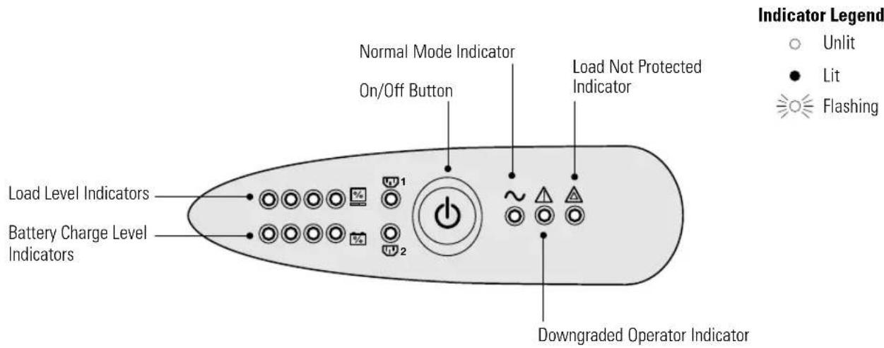
Figure 31. Alarm Indicators
Table 17. Troubleshooting Guide
| Alarm or Condition Possible Cause Action | ||
| When starting the UPS with the button, all the indicators turn on once, the alarm beeps once, and then indicator remains on. | The remote power-off (RPO) contact has been activated to shut down the UPS and now prevents restart. | Set the contact back to its normal position and press the button to restart. |
| The button, ~ and indicators are on and all the bar graph indicators flash. | The percent load is greater than the set overload level or UPS capacity. | Check the power drawn by the connected devices and disconnect any non-priority devices. Check the overload setting. |
| The button and indicator are on and all the bar graph indicators flash. | A critical overload has occurred. If utility power fails, the load will not be protected in Battery mode. | Check the power drawn by the connected devices and disconnect any non-priority devices. |
| The indicator is on and all the bar graph indicators flash. | A battery fault has been detected during the automatic test. | Replace the battery (see “Replacing Batteries” on page 48). |
| The indicator alone is on and the alarm sounds continuously. | UPS fault condition. The load is not supplied. | Contact your service representative. |
Service and Support
If you have any questions or problems with the UPS, call your Local Distributor or the Help Desk at one of the following telephone numbers and ask for a UPS technical representative.
United States: 1-800-356-5737
Canada: 1-800-461-9166 ext 260
All other countries: Call your local service representative
Please have the following information ready when you call the Help Desk:
- Model number
- Serial number
- Version number (if available)
- Date of failure or problem
•Symptoms of failure or problem - Customer return address and contact information
If repair is required, you will be given a Returned Material Authorization (RMA) Number. This number must appear on the outside of the package and on the Bill Of Lading (if applicable). Use the original packaging or request packaging from the Help Desk or distributor. Units damaged in shipment as a result of improper packaging are not covered under warranty. A replacement or repair unit will be shipped, freight prepaid for all warranted units.

NOTE For critical applications, immediate replacement may be available. Call the Help Desk for the dealer or distributor nearest you.
TROUBLESHOOTING
Chapter 9 Warranty
Two-Year Limited Warranty with Extension to Three-Year Limited Warranty (US and Canada)
Eaton UPS Models: 3105, 5110, 5115, 5125, and 5130
WARRANTOR: The warrantor for the limited warranties set forth herein is Eaton Corporation, an Ohio Corporation company ("Company").
LIMITED WARRANTY: This limited warranty (this "Warranty") applies only to the original End-User (the "End-User") of any Eaton 3105, 5110, 5115, 5125, and 5130 Products (individually and collectively, the "Product") purchased on or after August 19, 2009 and cannot be transferred. This Warranty applies even in the event that the Product is initially sold by Company for resale to an End-User.
LIMITED WARRANTY PERIOD: The period covered by this Warranty for Product installed [and currently located] in the fifty (50) United States, the District of Columbia, and Canada is twenty-four (24) months from the date of purchase, or thirty (30) months from the date of shipment. For units which are registered online at www.eaton.com/PQ/Register, the warranty is extended to thirty-six (36) months from the date of purchase, or forty-two (42) months from the date of shipment.
WHAT THIS LIMITED WARRANTY COVERS: The warrantor warrants that the Product and battery (individually and collectively, the "Warranted Items") are free from defects in material and workmanship. If, in the opinion of Company, a Warranted Item is defective and the defect is within the terms of this Warranty, Company's sole obligation will be to repair or replace such defective Warranted Item (including by providing service, parts and labor, as applicable), at the option of Company.
PROCEDURES FOR REPAIR OR REPLACEMENT OF WARRANTED ITEMS: The Warranted Item will be repaired or replaced at a Company site or such other location as determined by Company.
If the Warranted Item is to be replaced by Company, and the End-User supplies a credit card number or purchase order for the value of the replacement Product, Company will use commercially reasonable business efforts to ship (via standard ground shipment and at no cost to the End-User) the replacement Warranted Item to the End-User within one (1) business day after Company receives notice of the warranty claim. In such case, the End-User must return (at Company's expense) the defective Warranted Item to Company in the same packaging as the replacement Warranted Item received by the End-User or as otherwise instructed by Company. If Company does not receive the defective Warranted Item, Company will either charge the End-User's credit card, or send the End-User an invoice (which the End-User agrees to pay), for the value of the replacement Product.
If the Warranted Item is to be replaced by Company, but the End-User is unwilling or unable to supply a credit card number or purchase order for the value of the replacement Product, Company will use commercially reasonable business efforts to ship (via standard ground shipment and at no cost to the End-User) the replacement Warranted Item to the End-User within one (1) business day after Company receives the defective Product from the End-User.
In any case, Company will provide shipping instructions and will pay its designated carrier for all shipping charges for return of defective equipment and replacement of Warranted Items. Any returned Warranted Item or parts that are replaced may be new or reconditioned. All Warranted Items returned to Company and all parts replaced by Company shall become the property of Company.
WHAT THIS LIMITED WARRANTY DOES NOT COVER: This Warranty does not cover any defects or damages caused by: (a) failure to properly store the Product before installation, including the charge of batteries no later than the date indicated on the packaging; (b) shipping and delivery of the Product if shipping is FOB Factory; (c) neglect, accident, abuse, misuse, misapplication, or incorrect installation; (d) repair or alteration not authorized in writing by Company personnel or performed by an authorized Company Customer Service Engineer or Agent; (e) improper testing, operation, maintenance, adjustment, or modification of any kind not authorized in writing by Company personnel or performed by an authorized Company Customer Service Engineer or Agent; or (f) use of the Product under other than normal operating conditions or in a manner inconsistent with the Product's labels or instructions.
This Warranty is not valid if the Product's serial numbers have been removed or are illegible. Any Warranted Items repaired or replaced pursuant to this Warranty will be warranted for the remaining portion of the original Warranty subject to all the terms thereof.
Company shall not be responsible for any charges for testing, checking, removal, or installation of Warranted Items.
COMPANY DOES NOT WARRANT EQUIPMENT NOT MANUFACTURED BY COMPANY. IF PERMITTED BY THE APPLICABLE MANUFACTURER, COMPANY SHALL PASS THROUGH SUCH MANUFACTURER'S WARRANTIES TO END-USER.
COMPANY DOES NOT WARRANT SOFTWARE, INCLUDING SOFTWARE EMBEDDED IN PRODUCTS, THAT IS NOT CREATED BY COMPANY. WITHOUT LIMITING THE FOREGOING, COMPANY SPECIFICALLY DOES NOT WARRANT SOFTWARE (SUCH AS LINUX) THAT WAS CREATED USING AN "OPEN SOURCE" MODEL OR IS DISTRIBUTED PURSUANT TO AN OPEN SOURCE LICENSE.
THIS WARRANTY IS THE SOLE AND EXCLUSIVE WARRANTY OFFERED BY COMPANY WITH RESPECT TO THE PRODUCTS AND SERVICES AND, EXCEPT FOR SUCH FOREGOING WARRANTY COMPANY DISCLAIMS ALL OTHER WARRANTIES INCLUDING BUT NOT LIMITED TO ANY IMPLIED WARRANTIES OF MERCHANTABILITY, TITLE, NON-INFRINGEMENT, AND FITNESS FOR A PARTICULAR PURPOSE. CORRECTION OF NON-CONFORMITIES IN THE MANNER AND FOR THE PERIOD OF TIME PROVIDED ABOVE SHALL CONSTITUTE COMPANY'S SOLE LIABILITY AND END-USER'S EXCLUSIVE REMEDY FOR FAILURE OF COMPANY TO MEET ITS WARRANTY OBLIGATIONS, WHETHER CLAIMS OF THE END-USER ARE BASED IN CONTRACT, IN TORT (INCLUDING NEGLIGENCE OR STRICT LIABILITY), OR OTHERWISE.
LIMITATION OF LIABILITY: The remedies of the End-User set forth herein are exclusive and are the sole remedies for any failure of Company to comply with its obligations hereunder. In no event shall Company be liable in contract, in tort (including negligence or strict liability) or otherwise for damage to property or equipment other than the Products, including loss of profits or revenue, loss of use of Products, loss of data, cost of capital, claims of customers of the End-User, or any special, indirect, incidental, or consequential damages whatsoever. The total cumulative liability of Company hereunder whether the claims are based in contract (including indemnity), in tort (including negligence or strict liability), or otherwise, shall not exceed the price of the Product on which such liability is based.
Company shall not be responsible for failure to provide service or parts due to causes beyond Company's reasonable control.
END-USER'S OBLIGATIONS: In order to receive the benefits of this Warranty, the End-User must use the Product in a normal way; follow the Product's user's guide; and protect against further damage to the Product if there is a covered defect.
OTHER LIMITATIONS: Company's obligations under this Warranty are expressly conditioned upon receipt by Company of all payments due to it (including interest charges, if any). During such time as Company has not received payment of any amount due to it for the Product, in accordance with the contract terms under which the Product is sold, Company shall have no obligation under this Warranty. Also during such time, the period of this Warranty shall continue to run and the expiration of this Warranty shall not be extended upon payment of any overdue or unpaid amounts.
COSTS NOT RELATED TO WARRANTY: The End-User shall be invoiced for, and shall pay for, all services not expressly provided for by the terms of this Warranty, including without limitation, site calls involving an inspection that determines no corrective maintenance is required. Any costs for replacement equipment, installation, materials, freight charges, travel expenses, or labor of Company representatives outside the terms of this Warranty will be borne by the End-User.
OBTAINING WARRANTY SERVICE: In the USA, call the Customer Reliability Center 7x24 at 800-356-5737. Outside of the USA, call your local Eaton product sales or service representative. For comments or questions about this Warranty, write to the Customer Quality Representative, 3301 Spring Forest Road, Raleigh, North Carolina 27616 USA.
Load Protection Guarantee (US and Canada)
Eaton UPS Models 3105, 5110, 5115, 5125, and 5130
GUARANTOR: The Guarantor for the load protection guaranty set forth herein is Eaton Corporation, an Ohio Corporation company ("Company").
LIMITED GUARANTY: This load protection guaranty (this "Guaranty") applies only to the original End-User (the "End-User") of any Eaton 3105, 5110, 5115, 5125, and 5130 Products (individually and collectively, the "Product") and cannot be transferred. This Guaranty applies even in the event that the Product is initially sold by Company for resale to an End-User.
WHAT THIS GUARANTY COVERS: For the lifetime of the Product, Guarantor promises to repair or replace, at Guarantor's option, the equipment (valued up to the limits shown below*) that is damaged by an AC power line surge, spike, or other transient when properly connected to Guarantor's uninterruptible power system ("UPS"). Reimbursement for or restoration of data loss excluded. This Guaranty applies only if all of the following circumstances arise:
- The UPS is plugged into properly grounded and wired outlets, using no extension cords, adapters, other ground wires, or other electrical connectors;
- The installation of the UPS complies with all applicable electrical and safety codes described by the National Electrical Code ^® (NEC ^® );
- The UPS was used under normal operating conditions and in accordance with all labels and instructions; and
- The UPS was not damaged by accident (other than AC power line transient), misuse, or abuse.
*Cumulative Limits to be paid by Guarantor under this Load Protection Guaranty:
•\$25,000 for Eaton UPS Model 3105
- \$150,000 for Eaton UPS Models 5110, 5115, 5125, and 5130
WHAT THIS GUARANTY DOES NOT COVER: Any reimbursement or repair to End-User's equipment does not include reimbursement for or restoration of any data loss. This Guaranty does not cover any defects or damages caused by: (a) failure to properly store the Product before installation, including the charge of batteries no later than the date indicated on the packaging; (b) shipping and delivery of the Product if shipping is FOB Factory; (c) neglect, accident, abuse, misuse, misapplication, or incorrect installation of Product; (d) repair or alteration of Product not authorized in writing by Company personnel or performed by an authorized Company Customer Service Engineer or Agent; (e) improper testing, operation, maintenance, adjustment, or modification of any kind to the Product not authorized in writing by Company personnel or performed by an authorized Company Customer Service Engineer or Agent; or (f) use of the Product under other than normal operating conditions or in a manner inconsistent with the Product's labels or instructions.
This Guaranty is not valid: (a) unless the End-User returns to Company the Warranty Registration Card or completes the registration form on www.eaton.com/PQ/Register within thirty (30) days of purchase; or (b) if the Product's serial numbers have been removed or are illegible.
Company shall not be responsible for any charges for testing, checking, removal, or installation of any items.
LIMITATION OF LIABILITY: THE REMEDIES OF THE END-USER SET FORTH HEREIN ARE EXCLUSIVE AND ARE THE SOLE REMEDIES FOR ANY FAILURE OF COMPANY TO COMPLY WITH ITS OBLIGATIONS HEREUNDER. EXCEPT AS OTHERWISE PROVIDED FOR IN THIS GUARANTY, IN NO EVENT SHALL COMPANY BE LIABLE IN CONTRACT, IN TORT (INCLUDING NEGLIGENCE OR STRICT LIABILITY), OR OTHERWISE FOR DAMAGE TO PROPERTY OR EQUIPMENT OTHER THAN THE PRODUCTS, INCLUDING LOSS OF PROFITS OR REVENUE, LOSS OF USE OF PRODUCTS, LOSS OF DATA, COST OF CAPITAL, CLAIMS OF CUSTOMERS OF THE END-USER OR ANY SPECIAL, INDIRECT, INCIDENTAL, OR CONSEQUENTIAL DAMAGES WHATSOEVER. THE TOTAL CUMULATIVE LIABILITY OF COMPANY HEREUNDER WHETHER THE CLAIMS ARE BASED IN CONTRACT (INCLUDING INDEMNITY), IN TORT (INCLUDING NEGLIGENCE OR STRICT LIABILITY), OR OTHERWISE, SHALL NOT EXCEED THOSE SET FORTH ABOVE.
Company shall not be responsible for failure to provide repair or replacement under this Guaranty due to causes beyond Company's reasonable control.
END-USER'S OBLIGATIONS: In order to receive the benefits of this Guaranty, the End-User must use the Product in a normal way; follow the Product's user's guide; and protect against further damage to the Product if there is a covered defect.
OTHER LIMITATIONS: Company's obligations under this Guaranty are expressly conditioned upon receipt by Company of all payments due to it (including interest charges, if any). During such time as Company has not received payment of any amount due to it for the Product, in accordance with the contract terms under which the Product is sold, Company shall have no obligation under this Guaranty.
COSTS NOT RELATED TO GUARANTY: The End-User shall be invoiced for, and shall pay for, all services not expressly provided for by the terms of this Guaranty, including without limitation, site calls involving an inspection that determines no corrective maintenance is required. Any costs for replacement equipment, installation, materials, freight charges, travel expenses, or labor of Company representatives outside the terms of this Guaranty will be borne by the End-User.
TO MAKE A CLAIM: In the USA, call the Customer Reliability Center 7x24 at 800-356-5737. Outside of the USA, contact your local Eaton product sales or service representative. For comments or questions about this Load Protection Guaranty, write to the Customer Quality Representative, 3301 Spring Forest Road, Raleigh, North Carolina 27616 USA.

- Requesting a Declaration of Conformity
- Class A EMC Statements (Low-Voltage Models)
- FCC Part 15
- EN 62040-2
- Class B EMC Statements (High-Voltage Models)
- Special Symbols
- Table of Contents
- Specifications 53
- Troubleshooting 61
- Warranty 65
- Chapter 1 Introduction
- Chapter 2 Safety Warnings
- IMPORTANT SAFETY INSTRUCTIONS SAVE THESE INSTRUCTIONS
- DANGER
- WARNING
- CAUTION
- Chapter 3 Installation
- Inspecting the Equipment
- Checking the Accessory Kit
- Connecting the UPS Internal Battery
- UPS Setup
- Rackmount Setup
- Required Tools
- Installing the Rail Kit
- Tower Setup
- Installing the UPS
- RPO and ROO Installation
- UPS Rear Panels
- Chapter 4 Operation
- Turning the UPS On
- Starting the UPS on Battery
- Turning the UPS Off
- Operating Modes
- Normal Mode
- Battery Mode
- Standby Mode
- Chapter 5 Additional UPS Features
- USB Port
- Contact Communication Port (optional)
- Load Segments (PowerShare)
- Customizing the UPS with the UPS Configuration Tool
- Chapter 6 UPS Maintenance
- UPS and Battery Care
- Transporting the UPS
- Storing the UPS and Batteries
- When to Replace Batteries
- Replacing Batteries
- How to Replace Internal Batteries
- How to Replace Extended Battery Modules
- Recycling the Used Battery or UPS
- Chapter 7 Specifications
- Chapter 8 Troubleshooting
- Audible Alarms and UPS Conditions
- Service and Support
- Chapter 9 Warranty
- Two-Year Limited Warranty with Extension to Three-Year Limited Warranty (US and Canada)
- Load Protection Guarantee (US and Canada)
- Eaton UPS Models 3105, 5110, 5115, 5125, and 5130
Brand : EATON
Model : 5130 3000VA 2U
Category : Uninterruptible power supply