
MKT 290 - Air conditioner REMKO - Free user manual and instructions
Find the device manual for free MKT 290 REMKO in PDF.


| Type | Mobile Air Conditioner (Cooling only) |
| Model | MKT 290 / MKT 290 S-Line |
| Cooling Capacity (Nominal) | 2.94 kW |
| Energy Efficiency Class | A |
| EER | 2.69 |
| Temperature Setting Range | +16°C to +32°C |
| Operating Temperature Limits | +16°C to +35°C |
| Refrigerant Type | R410A |
| Refrigerant Quantity | 0.65 kg |
| Air Volume Flow | 240 / 270 / 320 m³/h |
| Sound Pressure Level | 45 / 50 / 53 dB(A) at 1 m |
| Power Supply | 230 V / 1~ / 50 Hz |
| Power Consumption | 1.09 kW |
| Current Consumption | 4.93 A |
| Starting Current | 21 A |
| Dimensions (H x W x D) | 700 x 435 x 430 mm |
| Weight | 32.0 kg |
| Protection Type | IP20 |
| Exhaust Hose (Length x Diameter) | 1200 mm x 125 mm |
| Operating Modes | Cool, Dehumidify, Fan (Circulation) |
| Control | Control panel + Infrared remote control |
| Timer | Automatic on/off (1-24 hours) |
| Filter Cleaning Interval | Every 100 hours of operation |
| Condensate Drain | Internal tank with plug; condensate pump for evaporation |
| Warranty | Per registration card and general terms |
Frequently Asked Questions - MKT 290 REMKO
User questions about MKT 290 REMKO
0 question about this device. Answer the ones you know or ask your own.
Ask a new question about this device
Download the instructions for your Air conditioner in PDF format for free! Find your manual MKT 290 - REMKO and take your electronic device back in hand. On this page are published all the documents necessary for the use of your device. MKT 290 by REMKO.
USER MANUAL MKT 290 REMKO
MKT 290, MKT 290 S-Line
Mobile Air Conditioner
Operation · Technology · Spare Parts
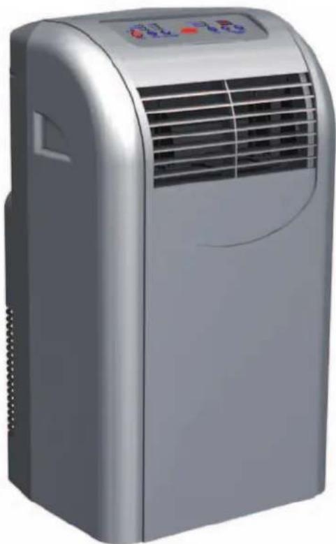
natural_image
Exterior view of a silver portable air conditioner unit (no visible text or symbols)Contents
| Safety notes | 4 |
| Environmental protection and recycling | 4 |
| Warranty | 4 |
| Intended use | 4 |
| Transport and packaging | 5 |
| Equipment description | 5 |
| Operation | 6-7 |
| Bevore Commissioning | 8-9 |
| Commissioning | 9 |
| Shut-down | 9-10 |
| Care and maintenance | 10 |
| Installation scheme of the wall through (optional) | 11 |
| Troubleshooting and customer service | 12 |
| Electrical connection diagram | 13 |
| Exploded view | 14 |
| Spare parts lists | 15 |
| Technical data | 16 |
| EC-Declaration of conformity | 17 |

Read these operating instructions carefully before commissioning / using the device!
These instructions are an integral part of the system and must always be kept near or on the device.
This operating manual is a translation of the German original.
Subject to modifications; no liability accepted for errors or misprints!
Safety notes
Carefully read the operating instructions before commissioning the equipment for service. It provides useful tips and information as well as hazard warnings to prevent injury or material damage ▲ Failure to follow the directions in this manual can result in endangerment to persons, the environment and the equipment itself and will void any claims for liability.
- Keep this manual and the refrigerant data sheet near the unit.
The unit should be set up and installed only by qualified personnel.
The set-up, connection, and operation of the unit and its components must be in accordance with the operating conditions stipulated in this manual and comply with all applicable local regulations.
■ Mobile units must be set up securely on suitable surfaces and in an upright position. Stationary units must be permanently installed for operation.
■ Modification of equipment and components supplied by REM-KO is not permitted and can cause malfunctions.
■ Equipment and components may not be operated in areas where there is an increased risk of damage. Observe the minimum clearances.
The electrical supply is to be adapted to the requirements of the equipment.
The operational safety of equipment and components is only assured if they are fully assembled and used as intended. Safety devices may not be modified or bypassed.
Do not operate equipment or components with obvious defects or signs of damage.
All housing parts and openings in the device, e.g. air inlets and outlets, must be free of foreign objects, fluids, or gases.
The equipment and components must be kept an adequate distance from flammable, explosive, combustible, abrasive and dirty areas or atmospheres.
■ Touching some parts of the equipment can result in burns or other injury.
Installation, repair and maintenance work may be carried out only by authorised specialists. Visual inspections and cleaning can be performed by the operator as long as power is disconnected from the equipment.
To preclude any danger from the equipment, take appropriate hazard-prevention measures when performing installation, repair or maintenance work or cleaning the equipment.
The equipment or components are not to be exposed to any mechanical stresses, extreme levels of humidity or direct sunlight.
Disposal of equipment and components
Only recyclable materials are used in the manufacture of the devices and components.
Help protect the environment by ensuring that the devices or components (for example batteries) are not disposed in household waste, but only in accordance with local regulations and in an environmentally safe manner, e.g. using certi-

fied firms and recycling specialists or at collection points.
Warranty
Prerequisites for possible warranty claims are customer or his accepting representative has completely filled out the "warranty registration card" supplied with the unit and was completely filled out and returned to REMKO GmbH & Co. KG and placing the unit in service. The warranty conditions are listed in the "General terms and conditions". Furthermore, only the parties to a contract can strike special agreements beyond these conditions. For this reason please contact your contractual partner in the first instance.

Environmental protection and recycling
Disposal of packaging
All products are packed for transport in environmentally friendly materials. Make a valuable contribution to reducing waste and sustaining raw materials. Only dispose of packaging at approved collection points.
Intended use
Depending on the model, the equipment and the additional fittings with which it is equipped is only intended to be used as an air-conditioner for the purpose of cooling or heating the air in an enclosed room.
Different or additional use shall not be classed as intended use. The manufacturer/supplier assumes no liability for damages arising from an unintended use of the equipment. The user bears the sole risk in such cases.
Using the equipment as intended also includes working in accordance with the operating manual and installation instructions and complying with the maintenance requirements.
Transport and Packaging
The equipment is shipped in sturdy transport packaging. Immediately check the equipment on delivery and make note of any damage or missing parts on the delivery note and inform the forwarding agent and your contractual partner. No warranty can be assumed for later claims.
Equipment description
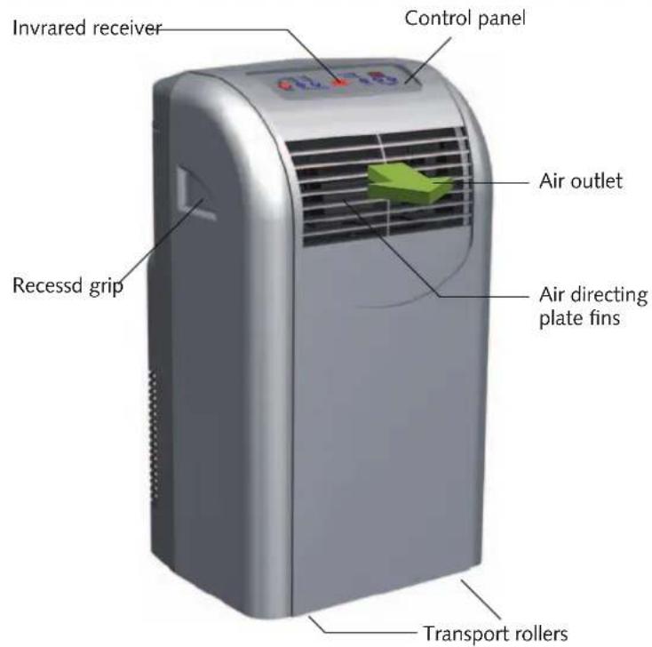
The device is particularly suited for flexible operation.
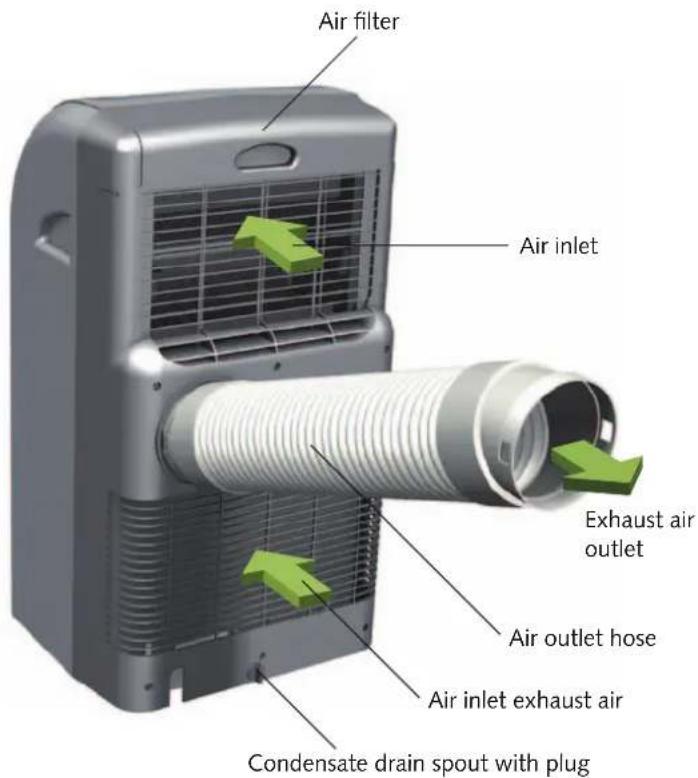
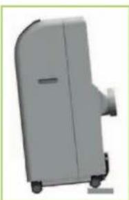
The mobile air conditioning unit is comprised for setting up on the floor indoors. and has an exhaust tube to dissipate the heat..
The indoor unit will located in the room to be cooled heat in the evaporator (heat exchanger) and transfers it to the internal cooling circuit. This is the heat of a further heat exchanger (condenser) via the flexible exhaust hose into the open again.
The condensate collected during cooling operation is transported to the outdoor unit by means of a condensate pump integrated into the indoor unit and evaporates via the heat exchanger.
The device filters and dehumidifies the air and thereby creates a comfortable room climate. It works fully automatically and offers numerous additional options thanks to its microprocessor control system. The device can be conveniently operated by means of the infrared remote control unit included.
Front view
Rear view
REMKO MKT
Operation
The system can be operated by means of the control panel on the device or via the standard infrared remote control unit. The functional operation of the buttons among themselves is identical, however, the designation can vary. The batteries must be correctly inserted before the infrared remote control is used.
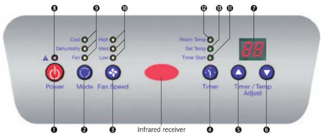
Control panel
Infrared remote control
Infrared transmitter
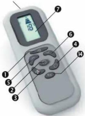
Legend
① ON / OFF „Power“ button
② „Mode“ button
③ „Fan Speed“ button
④ "Timer" button
⑤+⑥ Temperature/time setting buttons
„Timer/Temp Adjust“:
⑤ higher, ⑥ lower
⑦ Display
8 Red fault LED: Reservoir full
An acoustic and an optical signal indicate that the float switch of the internal reservoir has shut down the operation of the device.
The acoustic signal dies down after a short period of time, but the LED remains active.
⑨ Mode LED display
Green: "Cool" Orange: "Dehumidify" Yellow: "Fan"
10 Orange LED display for the fan speed, with high/medium/low speed "High"/"Med"/"Low"
⑪ Green LED display for the time delay, "Timer"
⑫ Green "Room Temp" LED (If this LED lights up the current room temperature is shown in the display ?)
⑬ Green "Set Temp" LED
⑭ "°C/°F" toggle button (only on the remote control)
„Mode“ selection
"Cool"
The device is used to cool the room. It filters and dehumidifies the air and thus creates a pleasant room climate.
„Dehumidify“
In the "Dehumidify" mode, humidity is removed from the air.
„Fan“
The device circulates the air, filters it, and creates an even air flow..
"Cool" mode
-
Attach the air outlet hose to the wall bushing or the window.
-
Activate the device using the "Power" button ①
-
Press the "Mode" button ② until the "Cool" LED lights up.
-
Select the fan setting using the "Fan Speed" button ③
"High" highest speed "Med" medium speed "Low" lowest speed
-
If the "Room Temp." LED ^12 lights up, the current room temperature is shown in the display ^7
-
As soon as the 4,5 button is pressed, the display switches from the room temperature to the set temperature (LED lights up) and shows the desired temperature for 15 seconds.
-
Set the desired room tem-Set the desired room time-setting "Timer/perature using the "Timer/Temp. Adjust" button 5 6 The up arrow 5 increases the set value shown in the display 7 while the down arrow 6 decreases it.
„Dehumidify“ mode
-
Attach the air outlet hose to the wall bushing or the window.
-
Activate the device using the "Power" button ①
-
Press the "Mode" button ② until the "Dehumidify" LED ⑨ lights up; the fan is automatically switched to the "Med" or medium fan speed stage.
„Fan“ mode
-
Activate the device using the "Power" button ①
-
Press the "Mode" button ② until the "Fan" LED ⑨ights up.
-
Select the fan setting using the "Fan Speed" button ③
"High" highest speed "Med" medium speed "Low" lowest speed
- The room temperature is not in-The rocailytemperade is not influenced and remains constant. For this reason, the tempera-
"Timer" time delay
You can turn the device on and off automatically using the timer. To do so, an activation/deactivation delay is programmed.
Automatic activation
-
Activate the device using the "Power" button ①
-
Select the mode and make all settings for the desired mode.
-
Deactivate the device using the "Power" button ①
-
Press the "Timer" button ④
-
Set the time using the "Timer/Temp. Adjust" button ⑤ ⑥ Only whole hours can be entered.
-
The LED ⑪flashes.
-
The device activates automati-The devi
Automatic deactivation
-
The device is running in the previously set mode.
-
Press the "Timer" button ④
-
Set the remaining run time us-Set the running the "Timer/Temp. Adjust" button ⑨.⑥ Only whole hours can be entered.
-
The LED Ⓞfleshes.
-
The device deactivates auto-The device matically at the set time.

TIP
You can achieve a pleasant room climate by selecting a set temperature that is a maximum of 4 to 7°C below the outdoor temperature.
REMKO MKT
Bevore Commissioning
The device is placed at the desired location, with the outlet side to the room. Note the list the following information.
Allow the device to the box at least 5 minutes stand on its transport wheels before operating it.
Place the unit stable on a flat, stable surface. Uneven floors
can cause vibration and unwanted noise.
natural_image
3D rendered image of a gray industrial machine or device component (no visible text or symbols)All extensions of the power line must have a correct cross section and may be used only fully rolled out.
Never operate the unit without the intake filter. Without an air intake filter, the plate fins of the evaporators become dirty and the unit's perfosely affected.
Make sure that people and objects, such as plants in the room, are not directly in the path of the expelled air.
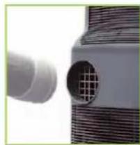
Make sure that the deflector piece from the top slides down into the notches on the side until it clicks into places. To ensure that the unit operates effectively, do not place the flexible exhaust hose supplied at sharp angles and make sure there are no kinks.
The air expelled from the unit contains a certain amount therefore reco the air to the outside.
natural_image
Close-up of a white cylindrical device with a grid-patterned circular opening, no visible text or symbolsCAUTION
From the back of the device to the back of the wall must be a minimum distance of about 20 cm.
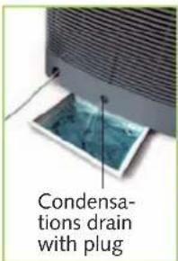
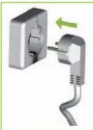
Check that the plug-in of condensation drain placed available and that is correct.
There is a risk of un-controlled condensate outlet is after commissioning.
natural_image
Close-up of a white electrical plug with a black outlet and a green arrow indicating direction (no text or symbols)TIP
In case of direct sunlight, make sure to close all curtains and blinds. Keep doors and windows closed during operation.
Expelling the warm air
CAUTION
The exhaust hose is always embarrassed with a pitch in air direction and should not be extended!
During cooling mode, the unit generates warm air. This air must be expelled from the room to retain the cooling effect.
It is therefore necessary to insert the supplied exhaust hose into the air outlet opening at the back of the unit.
Different ways of expelling air
You can expel air from the building as follows:
With a flat nozzle.
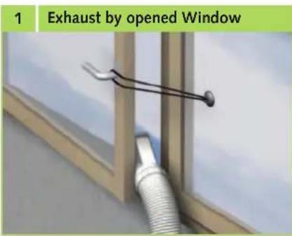
The flat nozzle supplied can be used in different ways. It is possible to guide the flat nozzle through the open window and se cure it firmly using straps and suction devices. (Fig. 1, page 9).
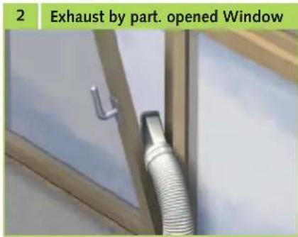
The flat nozzle can also be hung through the partially opened window (Fig. 2, page 9).
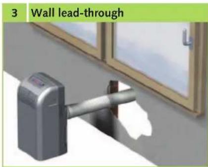
Wall lead-through
The hose supplied is firmly connected to a wall lead-through. Lead-through kits can be purchased as accessories. (Fig. 3).
natural_image
3D rendering of a wall-mounted device with a handle, placed near a window (no text or symbols visible)
NOTE
In some circumstances, low pressure can occur in the setup room when air is being expelled via a permanently attached exhaust hose, e.g. as a result of closed windows or doors. If the performance of the unit is adversely affected as a result, make sure that the pressure is corrected
Commissioning
Prior to initial operation, the air intake and outlet openings must be inspected for foreign bodies and the air in take filter for dirt. Blocked or dirty grilles and filters must be cleaned immediately. See the chapter "Maintenance and Service".
Cooling mode
- Switch the unit on with the "I/O" button..
- Select cooling mode with the "Mode" button. The "AUTO" LED must be lit up.
- Set the target temperature you want with the „TIMER/TEMP/ADJUST“ buttons. The selected target temperature appears on the display. If the set fan speed is too high or too low, the desired fan speed can be set by pressing the “FAN SPEED” button.
Fan mode (circulation)
- Switch the unit on with the "I/O" button
- Select fan mode with the "FAN SPEED" button. The LED „HIGH/MED/LOW" must be lit up.
Shut-down
Temporary Shut-down
If the unit is to be taken out of operation for a longer period of time, for example, over the winter, proceed as follows:
- Let the device run for approximately 2 hours in circulation mode (FAN) to dry the surface of the evaporator plate fins. This removes the remaining moisture from the unit and prevents unpleasant odours when the device is put back into operation.
-
Switch off the unit by pressing the "I/O" button, unplug the unit from the power supply and roll up the power cord. Make sure that the cable is not bent and there are no kinks.
-
Place a suitable container under the condensation drain of the internal tank. The condensation drain is located at the bottom at the back of the unit.
-
Pull the plug from the condensation drain and collect the water that drains out.
-
Then replace the plug. Keep in mind that if there is no plug or it is inserted incorrectly, water may leak out after the unit has resumed operation.
-
Store the unit in an upright position in a dry location. that is protected from direct sunlight and dust. To prevent dust from getting inside the unit, protect it with, for example, a plastic cover.
Permanent shut-down
The entire system should only be dismantled by a specialist firm familiar with all environmental aspects involved.
REMKO GmbH & Co. KG or your sales partner will be pleased to provide details of refrigerant specialists in your area.
Care and maintenance
Regular care and observation of some basic points will ensure trouble-free operation and a long service life of the unit.

CAUTION
Prior to performing any work, ensure the equipment is disconnected from the voltage supply and secured to prevent accidental switch-on!
- Clean the equipment using a damp cloth.
Do not use a jet of water.
Do not use any caustic, abrasive or solvent-based cleaning products.
Only use suitable cleaning agents, even in the event of severe soiling.
Make sure that no moisture gets into the device. Clean regularly and thoroughly, the exhaust air inlet and outlet openings. There is usually collected first on dirt.
It is recommended that you take out a maintenance contract with an appropriate specialist firm.
Cleaning the filter
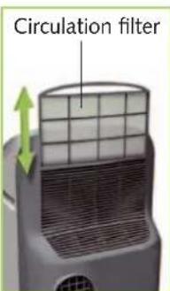
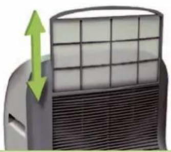
The unit is equipped with two air intake filters. These can be removed from the back of the unit. The filters must be cleaned at regular intervals. Clean the air filters after no more than 100 hours of operation. If the air is heavily contaminated, reduce this time period accordingly.
- Switch the unit off with the On/Off button on the control panel.
- Remove the filter from the unit. (Fig. 4).
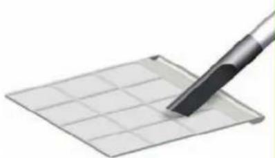
- Clean the dust that has accumulated from the filter. You can use a vacuum cleaner. (Fig. 5).
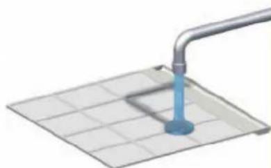
- If the dust filter is very dirty, wash it with a lukewarm soap solution (Fig. 6).
- Let the filter air dry.
- Replace the filter in the unit. (Fig. 4).
- Make sure that the filter is dry and undamaged.

CAUTION
Never operate the unit without the air filter.
4
Filter change
natural_image
Close-up of a car air conditioner unit with grid panel and upward arrow indicator (no text or symbols)5
Cleaning with a vacuum cleaner
natural_image
Close-up of a pen tip touching a grid-patterned surface (no text or symbols visible)6
Cleaning with lukewarm water
natural_image
3D illustration of a pipe inserted into a grid-patterned surface with a blue anchor (no text or symbols)Installation scheme of the wall through (optional)
Installation example
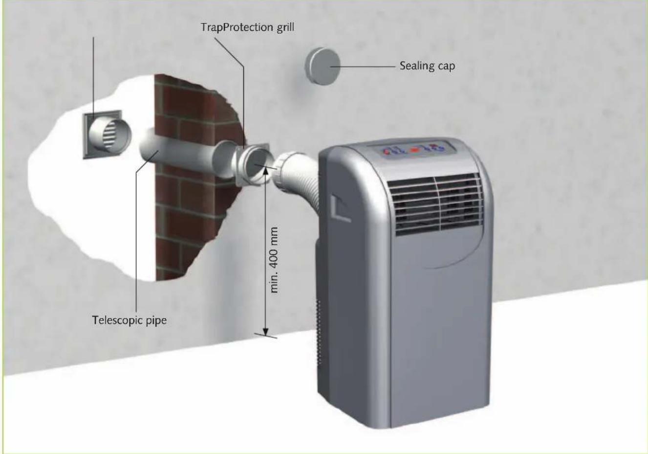
Installation Instructions
- Create a core hole in the outside wall (max.- wall thickness of 480 mm) with a diameter of at least 135 mm.
Note possible supply lines in this area!
- Insert the telescopic pipe in the created wall opening so that is the outer pipe (large diameter) on the inside wall.
To prevent cold bridges, insulate the telescopic pipe with suitable insulating material.
-
Wall the telescopic pipe into the core hole in such a way that it is flush to both sides of the wall.
-
Mount the protection grill on the outside of the wall with 4 screws (make sure it is protected from rain).
-
Fix the trap to the inside and mount it with 4 screws..
The "top" label on the trap must be legible from the inside!
- When taking the device out of service, for example, at the beginning of winter, close the opening of the trap using the sealing cap to prevent air circulation.
Troubleshooting and customer service
The unit has been manufactured using state-of-the-art production methods and tested several times to ensure its correct function. If malfunctions should occur, please check the unit as detailed in the list below. If all functional checks have been carried out and the device still fails to operate properly, then please notify your nearest specialist dealer.

CAUTION
Never open the device housing.
The device is not functioning and the control panel remains dark.
Make sure that
- the mains plug is properly inserted;
- there is no power failure;
- the mains voltage is present (fuse)
- Check the mains supply line for damage.

NOTE
Contact your dealer or contractual partner if the device cannot be commissioned.
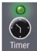
The device is not functioning and the "Timer" time delay LED is flashing.
- "Timer" time delay is programmed. Delete the timer setting.
The device is not functioning and "E1" is being shown in the display
The room temperature lies outside the operating range of
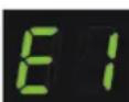
16 to 35°C. Wait until the room temperature lies in the working range (reduce the incident of sunlight and close windows and doors, if necessary).
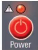
The device deactivates automatically.
The fault LED flashes and a signal sounds (reservoir full).
To drain the reservoir, proceed as follows:
- Switch off the device and pull the mains plug.
- Place a flat tray under the condensate drain spout and remove the plug.
- After the condensate has drained, reinsert the plug firmly.
The device is not cooling properly.
- Check the mode: the "Cool" LED must be lit.
For an optimum cooling capacity, close the curtains and blinds. In addition, make sure the windows and doors are closed.
Make sure that
- the air outlet hose has been properly attached. It may not be bent, declining, or laid in a tight curve;
- no foreign bodies impair the exhaust or intake air supply (observe the minimum clearances);
- the air directing plate fins are free of soiling or foreign objects
- the set temperature is not too high (operating limits of the device: 16 to 35^ ).
The device does not react to the remote control.
Make sure that
- the batteries are functioning; change them if necessary;
- the batteries are inserted with the correct polarity (cf. the marking);
- there are no objects between the remote control and the device (reach of approx. 5 m).
Condensate is emerging.
Make sure that
- the device is on a horizontal foundation;
- the air outlet hose is properly attached;
- the plug is firmly inserted in the condensate drain spout.

CAUTION
Never perform work on the cooling circuit or the electrical equipment..
Electrical connection diagram
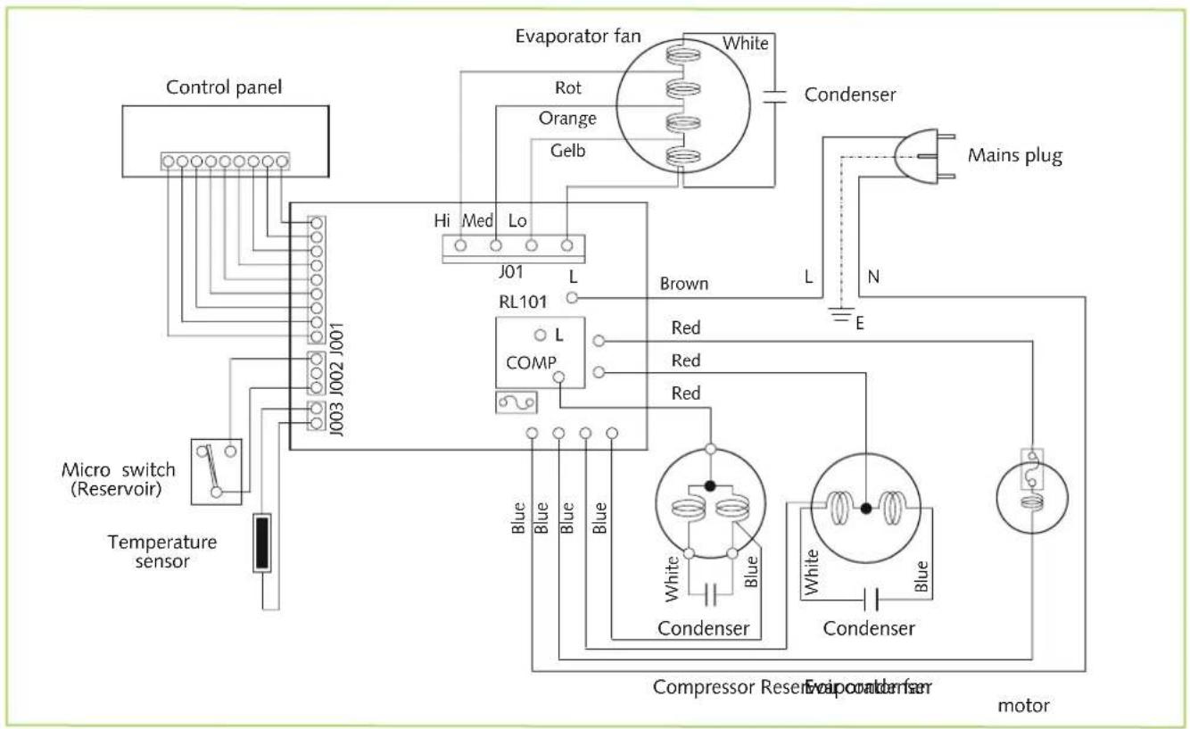
flowchart
graph TD
    A["Control panel"] --> B["J003 J002 J001"]
    B --> C["Micro switch (Reservoir)"]
    C --> D["Temperature sensor"]
    D --> E["Motor"]
    F["Evaporator fan"] --> G["White"]
    F --> H["Condenser"]
    I["RL101"] --> J["L"]
    K["COMP"] --> L["L"]
    M["Condenser"] --> N["White"]
    M --> O["Condenser"]
    P["Motor"] --> Q["Avaporator fan"]
    R["Mains plug"] --> S["N"]
    T["Blue Blue Blue Blue Blue"] --> U["Red Red Red"]
    V["Blue Blue Blue Blue Blue"] --> W["Red Blue Blue Blue"]
    X["Blue Blue Blue Blue Blue"] --> Y["Red Blue Blue Blue Blue"]
    Z["Blue Blue Blue Blue Blue"] --> AA["Red Blue Blue Blue Blue"]
    AB["Green Cable"] --> AC["Orange"]
    AD["Power Supply"] --> AE["Inductor"]
    AF["Ground"] --> AG["Power Supply"]
REMKO MKT
Exploded view
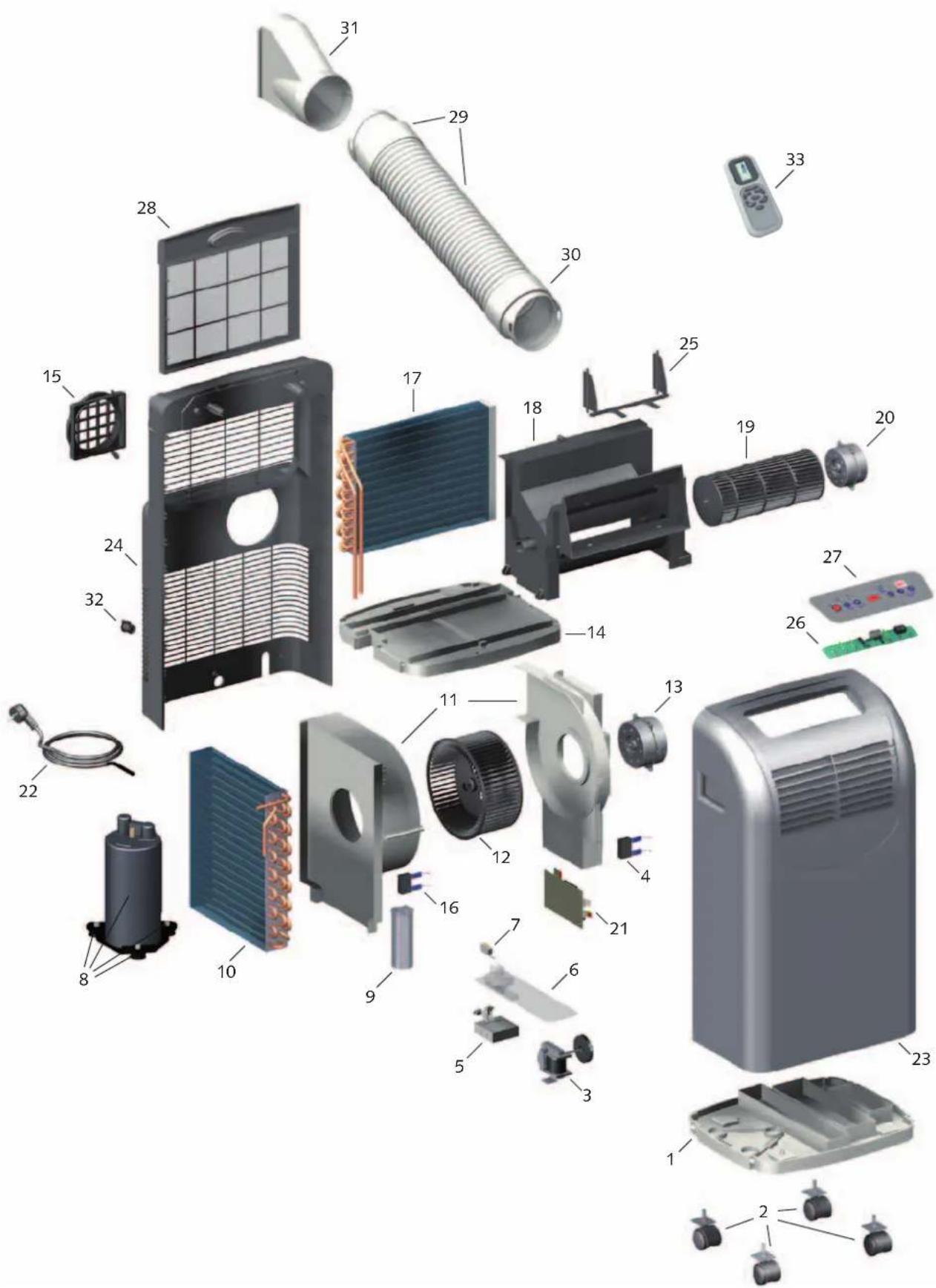
We reserve the right to modify the dimensions and constructional design as part of the ongoing technical development process.
Spare parts list
| No. | Designation | MKT 290 | MKT 290 S-LINE |
| From series number 77285001 77285001 | |||
| 1 | Unit bottom 1106850 1106850 | ||
| 2 | Transport roller 1106851 1106851 | ||
| 3 | Condensate pump 1106852 1106852 | ||
| 4 | Condenser 2.5 μF (evaporator fan) | 1106853 1106853 | |
| 5 | Float regulator (reservoir) 1106854 1106854 | ||
| 6 | Cover (reservoir) 1106855 1106855 | ||
| 7 | Microswitch (reservoir) | 1106856 1106856 | |
| 8 | Compressor, cpl 1106898 1106898 | ||
| 9 | Condenser 40 μF (compressor) 1106892 1106892 | ||
| 10 | Evaporator 1106895 1106893 | ||
| 11 | Fan housing (exhaust air) 1106860 1106860 | ||
| 12 | Fan wheel (exhaust air) 1106861 1106861 | ||
| 13 | Fan motor (exhaust air) 1106863 1106863 | ||
| 14 | Condensate tray | 1106824 1106824 | |
| 15 | Exhaust air pipe adapter | 1106865 1106865 | |
| 16 | Condenser 1,5 μF | 1106866 1106866 | |
| 17 | Evaporator 1106896 1106896 | ||
| 18 | Fan housing (circulation air) | 1106822 1106822 | |
| 19 | Fan wheel (circulation air) | 1106823 1106823 | |
| 20 | Fan motor (circulation air) | 1106843 1106843 | |
| 21 | Circuit board | 1106873 1106873 | |
| 22 | Mains supply line with plug | 1106874 1106874 | |
| 23 | Front wall | 1106820 1106827 | |
| 24 | Back wall | 1106829 1106829 | |
| 25 | Air outlet segment | 1106844 1106844 | |
| 26 | PCB with control | 1106825 1106825 | |
| 27 | Control panel | 1106826 1106831 | |
| 28 | Air filter | 1106830 1106830 | |
| 29 | Entry circuit | 1106886 1106833 | |
| 30 | Connection pipe adapter | 1106887 1106834 | |
| 31 | Window jet | 1106888 1106835 | |
| 32 | Condensate drain spout with plug | 1106882 1106882 | |
| 33 | Remote control | 1106884 1106884 | |
| Air outlet hose, cpl. (nr. 29; 30; 31) | 1106885 1106832 | ||
| Spare parts without Abbildung | |||
| Sensor (circulation air) | 1106889 1106889 | ||
Accessories
| No. | Designation | MKT 290 | MKT 290 S-LINE |
| Wall bushing | 1613115 1613115 |
When ordering spare parts, please state the computerised part no., unit number and type (see identification plate)!
Technical Data
| Device type | MKT 290 | MKT 290 S-LINE | |
| Operating mode Mobile Air Conditioning Unit for cooling | |||
| Nominal cooling capacity1) | kW 2,94 | ||
| Energy efficiency class, cooling A | |||
| Energy efficiency factor EER1) | 2,69 | ||
| Application range (room air volume), approx. m380 | |||
| Temperature setting range °C +16 up to +32 | |||
| Temperature operating limits °C /%r.F. +16 bis +35 / +35 bis +85 | |||
| Refrigerant R 410A | |||
| Operating pressure max., cooling circle kPa 1800 / 3600 | |||
| Refrigerant quantity kg | 0,65 | ||
| Circulation air volume flow rate | m3/h | 240 / 270 / 320 | |
| Sound pressure level2) | dB(A) | 45 / 50 / 53 | |
| Voltage supply | V/Hz | 230 / 1~ / 50 | |
| Type of protection | IP | 20 | |
| Power consumption1) | kW 1,09 | ||
| Current consumption1) | A | 4,93 | |
| Electrical starting current | A | 21 | |
| Air outlet hose, diameter | mm/mm | 1200 / 125 | |
| Diemsions Height | mm | 700 | |
| Width | mm | 435 | |
| Depth | mm | 430 | |
| Weight | kg | 32,0 | |
| Color | white | silver | |
| Serial no. | 772... | 773... | |
| Ref.no. | 1612290 | 1612291 | |
1) Room temperature TK 35°C / FK 24°C
2) Distance 1 m
EC – Declaration of Conformity
(in accordance with Machinery Directive appendix II 1A - Original declaration of conformity)
CE
We do hereby declare that the devices named below, produced and sold by us, satisfy the relevant basic requirements of the EC guidelines, the EC safety standards and other product-specific EC standards.
Name of Manufacturer: REMKO GmbH & Co. KG
Air conditioning and heating technology
Im Seelenkamp 12
D - 32791 Lage
Name of CE representative: REMKO GmbH & Co. KG
Air conditioning and heating technology
Im Seelenkamp 12
D - 32791 Lage
Equipment (machinery) - Implementation: Mobile Air Conditioning Unit for cooling
Series / Model: REMKO MKT 290, MKT 290 S-Line
Series / Class Number: 772...... and 773......
Applicable regulations : MA - RL 2006/42/EC Machinery Directive
(EC-Directive) NS - RL 2006/95/EC Low-Voltage Directive
EMC - RL 2004/108 EEC EMC Directive
EnVKV - RL 92/75/EEC Energy consumption labelling directive
EC 97/23/EC Pressure Equipment Directive
Applicable Standards: DIN EN ISO 12100-1-2 : 2004-04; DIN EN ISO 13857,
EN 14511 T1-4;
DIN 45635 - 1;
EN 378-1-4;
EN 55014 - 1; EN 55014 - 2; EN 55104
EN 60204 - 1; EN 60335 - 1; EN 60335 - 2 - 40;
EN 61000 - 3 - 2; EN 61000 - 3 - 3;
REMKO GmbH & Co. KG Air conditioning and heating technology
Air conditioning and heating technology
+49 5232 606-0
Export
+49 5232 606-130
Die Beratung
natural_image
Three flags waving in front of a pole, featuring the European Union flag and national flags (no text or symbols visible on flags beyond the emblem design)- Contents
- Safety notes
- Disposal of equipment and components
- Warranty
- Environmental protection and recycling
- Disposal of packaging
- Intended use
- Transport and Packaging
- Equipment description
- REMKO MKT
- Operation
- Legend
- „Mode“ selection
- "Cool" mode
- „Dehumidify“ mode
- „Fan“ mode
- "Timer" time delay
- Automatic activation
- Automatic deactivation
- TIP
- Bevore Commissioning
- CAUTION
- Expelling the warm air
- Different ways of expelling air
- With a flat nozzle.
- Wall lead-through
- NOTE
- Commissioning
- Cooling mode
- Fan mode (circulation)
- Shut-down
- Temporary Shut-down
- Permanent shut-down
- Care and maintenance
- Cleaning the filter
- Installation scheme of the wall through (optional)
- Installation example
- Installation Instructions
- Troubleshooting and customer service
- The device is not functioning and the control panel remains dark.
- The device is not functioning and the "Timer" time delay LED is flashing.
- The device is not functioning and "E1" is being shown in the display
- The device deactivates automatically.
- The fault LED flashes and a signal sounds (reservoir full).
- The device is not cooling properly.
- The device does not react to the remote control.
- Condensate is emerging.
- EC – Declaration of Conformity
- CE
- Die Beratung
Brand : REMKO
Model : MKT 290
Category : Air conditioner