
X95i - Projector 3M - Free user manual and instructions
Find the device manual for free X95i 3M in PDF.


| Product Type | Video Projector |
| Brand | 3M |
| Model | X95i |
| Display Technology | LCD (3-chip) |
| Native Resolution | XGA (1024 x 768) |
| Brightness (ANSI Lumens) | 3000 |
| Contrast Ratio | 500:1 |
| Lamp Life (Normal Mode) | 2000 hours |
| Lamp Life (Eco Mode) | 3000 hours |
| Projection Lens | Manual zoom and focus |
| Keystone Correction | Vertical +/- 30 degrees |
| Inputs | VGA, S-Video, Composite, Audio In |
| Outputs | Monitor Out, Audio Out |
| Built-in Speaker | 1 x 8W |
| Dimensions (W x D x H) | 327 x 263 x 115 mm (12.9 x 10.4 x 4.5 in) |
| Weight | 3.6 kg (7.9 lbs) |
| Power Consumption (Max) | 310 W |
| Power Supply | 100-240V AC, 50/60 Hz |
| Noise Level (Normal) | 35 dB |
| Main Functions | Data/video projection, presentations, home theater |
| Maintenance and Cleaning | Clean air filter every 100 hours; replace lamp when needed |
| Safety Precautions | Do not look into lens; ensure ventilation; use grounded outlet |
| Spare Parts and Repairability | Replacement lamps, filters, and service by authorized technicians |
| General Information | Designed for business and education use; manual available for download |
Frequently Asked Questions - X95i 3M
User questions about X95i 3M
0 question about this device. Answer the ones you know or ask your own.
Ask a new question about this device
Download the instructions for your Projector in PDF format for free! Find your manual X95i - 3M and take your electronic device back in hand. On this page are published all the documents necessary for the use of your device. X95i by 3M.
USER MANUAL X95i 3M
natural_image
Line drawing of a projector with visible lens and control panel (no text or symbols)Thank you for purchasing this projector.
This projector has the network function that brings you the following main features.
√ Live Mode
This projector can project your PC images on screen through wireless or wired network, which can erase a signal cable from your desk.
√ Quick connection to your network
No expert knowledge is required any more. Various options for network setting give you a quick and simple connection to the network.
√ Web control
The projector can be controlled and monitored by a web browser software on your PC, which can help you to setup and maintain the projector.
√ PC-LESS Presentation
This projector can project images stored in an SD memory or a USB memory on screen, which allow you not to bring your PC with you.
This manual is only intended to explain Network functions only.
For safety, operations or any other issues, refer to the Product Warranty and Safety Guide and Operator's Guide.
⚠ WARNING ▶ Before using this product, be sure to read all manuals for this product. After reading them, store them in a safe place for future reference.
NOTE • The information in this manual is subject to change without notice.
- The manufacturer assumes no responsibility for any errors that may appear in this manual.
- The reproduction, transfer or copy of all or any part of this document is not permitted without express written consent.
Trademark acknowledgment
- Microsoft® and Internet Explorer®, Windows®, Windows NT®, Windows® Me, Windows® Vista are registered trademark of Microsoft Corporation.
- PowerPC ^ is a registered trademark of International Business Machines Corporation.
• VESA and DDC are trademarks of the Video Electronics Standard Association.
- Apple and Macintosh®, Mac®, Mac OS® are registered trademarks of Apple Inc.
- Pentium® is a registered trademark of Intel Corporation.
- JavaScript is a registered trademark of Sun Microsystems, Inc.
• DVI is a trademark of Digital Display Working Group.
- HDMI, the HDMI logo and High-Definition Multimedia Interface are trademarks or registered trademarks of HDMI Licensing LLC.
- SRS(●) is a trademark of SRS Labs, Inc. WOW technology is incorporated under license from SRS Labs, Inc.
All other trademarks are the properties of their respective owners.
Content
Content
[Non-Text]
Content 2
Caution 3
1. Main functions ..... 5
1.1 Live Mode (Project images from PC)..5
1.2 Quick connection to your network..6
1.3 Configuring and controlling via a web browser . . 7
1.4 PC-LESS Presentation
(Display the images stored in SD memory card/USB memory.) . . 8
2. Equipment connection and network setting .. 1 0
2.1 Required equipment preparation .. 1 0
2.2 Quick connection ..... 1 0
2.3 Manual network connection setting - Wired LAN - . . 1 1
2.3.1. Equipments connection . . . 1 1
2.3.2. Network settings ..... 1 1
2.3.3 "Internet Option" setting . . . . 1 4
2.3.4 Check connection ..... 1 5
2.4 Manual network connection setting -Wireless LAN..16
2.4.1 Preparation for wireless LAN connection.. 1 6
2.4.2 Wireless LAN connection set up . . 1 7
3. Using the Live Mode ..... 2 0
3.1 Outline of the Live Mode.....2 1
3.1.1 Display mode ..... 2 1
3.1.2 Presenter mode....2 2
3.1.3 Display User Name ..... 2 2
3.2 Install "Live Viewer 3" ..... 2 3
3.2.1 Minimum PC hardware and software requirement.. 2 3
3.2.2 Software Installation Procedure..24
3.2.3 Version of the "Live Viewer" software.. 2 5
3.3 Quick connection to the network. . 2 6
3.3.1 Starting the "Live Viewer 3". . 2 6
3.3.2 Selecting the network connection mode . . 2 7
3.3.3 Connecting to the network . . 3 1
3.4 Passcord connection ..... 3 2
3.4.1 Getting the Passcode ..... 3 2
3.4.2 Entering the Passcode .... 3
3.4.3 Configuring manually ..... 37
3.5 Manual configuration ..... 4 1
3.5.1 Profile connection ..... 4 1
3.5.2 History connection.....4 2
3.5.3 Configuring manually ..... 4 3
3.6 Confirm the connection to your destination..50
3.6.1 Connection and transmission..50
3.6.2 Connection error ..... 5 2
3.6.3 Setting the Live Mode ..... 5 3
[Non-Text]
3.7 Start the "Live Viewer 3" ..... 5 4
3.7.1 Main menu and Operating buttons . . 5 4
3.7.2 Displaying the status ..... 5 6
3.7.3 Switching the display mode . . 5 7
3.7.4 Option menu ..... 5 8
3.8 Profile data 60
3.8.1 Outline of Profile data ..... 6 0
3.8.2 Making Profile data ..... 6 0
3.8.3 Editing Profile data ..... 6 1
3.8.4 Registering My Connection . 6 2
4. Management with Web browser software..64
4.1 Configuring and controlling the projector via a web browser .. 6 5
4.1.1 Logon 67
4.1.2 Network Information ..... 6 8
4.1.3 Network Settings ..... 6 9
4.1.4 Port Settings ..... 7 1
4.1.5 Mail Settings ..... 7 2
4.1.6 Alert Settings....73
4.1.7 Schedule Settings ..... 7 5
4.1.8 Date/Time Settings ..... 7 7
4.1.9 Security Settings ..... 7 9
4.1.10 Projector Control ..... 8 1
4.1.11 Remote Control ..... 8 6
4.1.12 Projector Status.....8 8
4.1.13 Network Restart ..... 8 9
4.1.14 Logoff 89
4.2 E-mail Alerts 90
4.3 Projector Management using SNMP..92
4.4 Event Scheduling ..... 9 3
4.5 MY IMAGE (Still Image Transfer) Display . . 9 6
4.6 Command Control via the Network..97
5. PC-LESS Presentation....102
5.1 Outline of the PC-LESS Presentation. . 102
5.2 Thumbnail mode ..... 1 0 4
5.2.1 Starting the Thumbnail mode.. 104
5.2.2 Operating by buttons or keys.. 106
5.2.3 Operation on the Thumbnail menu .. 107
5.3 Full Screen Mode ..... 1 0 8
5.4 Slide Show Mode ..... 1 1 0
5.5 Directory Tree View.....1 1 2
5.6 "PC-LESS Presentation" error message .. 11 5
5.7 Playlist 11 6
6. Troubleshooting ..... 11 7
7. Specifications ..... 1 2 0
8. Warranty and after-sales service..121
Caution
[Restriction in terms of inserts or pulls storage media and wireless network card]
Do not pull out the wireless network card while the power is on. Do not touch the SD card while being accessed. The storage media can be pulled out only while not being accessed.
Perform the REMOVE MEDIA procedure or turn the projector off before pulling out the media. To perform the REMOVE MEDIA procedure, choose an suitable item among the REMOVE ALL, REMOVE SD CARD or REMOVE USB using the PC-LESS PRESENTATION menu under the MIU menu. (MIU menu in the Operator's Guide)
CAUTION
■The accompanying IEEE802.11b/g wireless network card uses the 2.4GHz radio frequency band. You do not need a radio license to use this card, but you should be aware of the following:
●DO NOT USE NEAR THE FOLLOWING!
- Microwave ovens
- Industrial, scientific or medical devices
- Designated low power radio stations
- Premises radio stations
Using the wireless network card near the above may result in radio interference, which in turn may result in a decrease in communication speed and even a complete loss of communication.
- Depending on the location where you attempt to use the wireless network card, there may be interference with the radio waves, which may result in a decrease in communication speed and even a complete loss of communication. In particular, please be aware that using the wireless network card in locations where there is reinforced steel, other metals and concrete may interfere with radio communication.
●Available Channels
The wireless network card uses the 2.4GHz radio frequency band, but depending on the country or region you are in, you might be limited to the channels you can use. Please refer to the following table for confirming where and with what channels you may use the accompanying IEEE802.11b/g wireless network card. Please consult with your dealer for countries not included in the table.
| Country or Region Available Channel | |
| Japan 1 to 11 | |
| USA 1 to 11 | |
| Taiwan 1 to 11 | |
| Canada 1 to 11 | |
| UK, Spain, Germany, Italy, Austria, Switzerland, Belgium, Sweden, Netherlands, Portugal, Denmark, Finland, Greece, Norway, France, Ireland, Luxembourg, Iceland | 1 to 11 |
- You may not bring the wireless network card into countries not listed above as there is a possibility that use of the wireless network card in those countries could lead to an infringement of established radio laws.
The manufacturer (Gemtek) hereby declare that this equipment (the wireless network card), model SD-Link11g is in compliance with the essential requirements and other relevant provisions of Directive 1999/5/EC.
1. Main functions
1.1 Live Mode (Project images from PC)
The MIU (Multi Information processing Unit) enables "Wireless presentation" by choosing Live Mode.
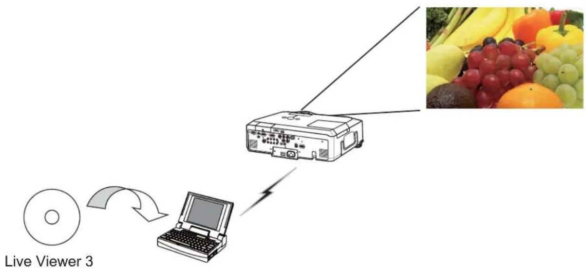
The Live Mode gives you an ability to display the same image that is shown on the PC through the network by using an application program "Live Viewer 3" that is required to install into your PC. (Fig.1.1.a)
The “Live Viewer 3” captures PC screen image and sends to the projector through wired LAN or wireless LAN connection. (20)
flowchart
graph TD
    A["CD"] -->|Data Transfer| B["Laptop"]
    B --> C["Printer"]
    C --> D["Product Image"]
    style A fill:#f9f,stroke:#333
    style B fill:#ccf,stroke:#333
    style C fill:#cfc,stroke:#333
    style D fill:#fcc,stroke:#333
Fig. 1.1.a "Live Viewer 3" outlines (through wireless LAN connection)
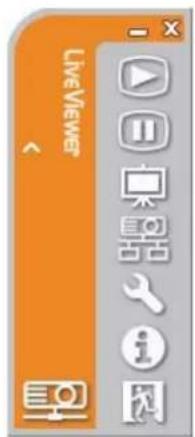
Fig. 1.1.b "Live Viewer 3" Main menu
One projector can be connected with up to 4 PCs using "Live Viewer 3". (54)
1.2 Quick connection to your network
The “Live Viewer 3” brings you very quick and simple connection to your network. The “Live Viewer 3” prepares some options for you to match your requirement.
1) Quick connection by the Passcode
The Passcode is a code that includes SSID and IP address and other information that are required for the network connection. The Passcode is given on screen by the projector, and then all you need to do is to input the code to the "Live Viewer 3" in your PC. (26)
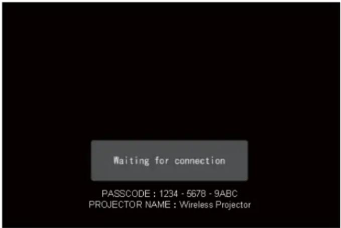
Fig.1.2 PASSCODE on the projector screen
2) Connection by the profile for the network
You can set the information to connect the projector to your network as a profile data in the “Live Viewer 3” in your PC. After that, you just select the profile data on the “Live Viewer 3” to connect the projector to your network.
3) Connection by the history record for the network
Once you connect the projector to your network with the "Live Viewer 3", the "Live Viewer 3" stores the history. You just select a history record to connect the projector to your network.
1.3 Configuring and controlling via a web browser
You can adjust or control the projector via a network from a web browser on a PC that is connected to the same network.
Logon the network from the web browser and it offers the menus to configure the network settings, monitor the projector and so on. The Web Remote Control, one of the menus of web browser, allows you to control the projector like bundled remote control including operating the "Live Mode" and "PC-LESS Presentation".
(64)
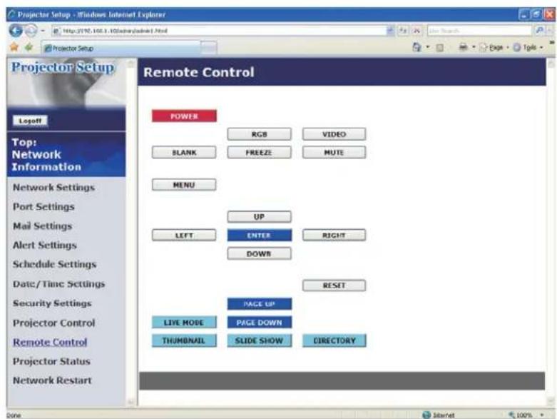
Fig. 1.3. Web Remote Control
1.4 PC-LESS Presentation
(Display the images stored in SD memory card/USB memory.)
The MIU enables "PC-LESS Presentation" by choosing PC-LESS function. (Fig. 1.4)
The PC-LESS function enables to display images that are stored in a storage media like SD memory card or USB memory. The “PC-LESS Presentation” has 4 types of display modes.
1) Thumbnail Mode: Display thumbnails of stored images in the storage media. (After this, "the storage media" is the general term for both of SD memory card and USB memory.)
2) Full Screen Mode: Display selected image or movie on the full screen mode.
3) Slide Show Mode: Display images in the Slide show mode with certain interval.
4) Directory Tree View: Display files and folders that are stored in the storage media as directory tree view.
[Supported storage media]
- SD memory card
- USB memory (USB memory type, USB hard disk and USB card reader type)
NOTE • USB memory reader (adapter) is not supported (if the adapter acknowledges as multiple devices connected).
• The supported formats are FAT 12, FAT 16(FAT) and FAT 32.
NTFS is not supported.
• USB hub is not supported.
![THUMBNAIL [SD] 1 2 3 4 5 6 7 8 9 10 11 12 PC LESS PRESENTATION MENU REFRESH SLIDE SHOW START #1 STOP #999 INTERVAL 10s MODE ONE TIME PLAY ENTER, Yes](/content/2026/05/843273/images/5e788732c491eeef27f9bf153feab411c98da6a2c9ec51befafc056a9e736d2f.jpg)
Fig. 1.4 "PC-LESS Presentation" outlines
"PC-LESS Presentation" can be controlled via keypad on the projector or remote control (102).
1.4 PC-LESS Presentation
(Display the images stored in SD memory card/USB memory.) (continued)
NOTE • There are several naming limitations for the folders and files.
(1) Alphanumeric and Japanese characters are supported if the language setting is Japanese.
(2) Alphanumeric and Latin-1 characters are supported if the language setting is NOT Japanese.
- The files may not be able to access depending on the type of USB hard disk, USB memory and USB card reader.
- It is recommended to use external power supply cable if the USB hard disk drive has the power cable.
2. Equipment connection and network setting
2.1 Required equipment preparation
The following equipments are required to connect the projector to your PC through the network.
■ Common The projector: 1 unit, PC : 1 set *1
It is recommended to install the "Live Viewer 3" into the PC.
■ Depending on how you want to connect
1) For the wired connection
LAN cable (CAT-5 or greater): 1 piece
2) For the wireless connection *2
- Projector side
The Wireless Network Card (option : VA0833x *4) : 1 unit
- PC side
IEEE802.11b/g wireless LAN equipment: 1 unit *3
*1: For the PC, please refer to the item 3.2.1 Minimum PC hardware and software requirement. (23)
*2: An access point is required when the wireless LAN connection is used as Infrastructure mode.
*3: Depending on the type of wireless network device and PC you are using, the projector may not be able to communicate properly with your PC, even if the PC you are using is equipped with built-in wireless LAN function.
To eliminate communication problems, please use a Wi-Fi certified wireless network device.
*4: For more information, please consult your dealer.
2.2 Quick connection
The “Live Viewer 3” supports very quick and simple connection to the network. It is strongly recommended to install the “Live Viewer 3” into your PC to enjoy the feature. Proceed to the installation of the “Live Viewer 3” (23) and the connection. (26)
In case you don't want to use the "Live Viewer 3" or you cannot use it by some reason, proceed to the manual setting, the item 2.3 for the wired LAN (11) and the item 2.4 for the wireless LAN. (16)
2.3 Manual network connection setting - Wired LAN -
If you don't use the "Live Viewer 3", you need to set up your network connection manually.
This section explains how to set it up manually.
2.3.1 Equipments connection
Connect the projector and PC with a LAN cable.
* Before connecting with an existing network, contact the network administrator.
Next, please check the PC setting as explained below.
2.3.2 Network settings
This is the explanation of network connection settings for Windows® XP and Internet Explorer®.
1) Log on to Windows® XP as administrator authority. (*)
2) Open "Control Panel" from "Start" menu.
3) Open "Network and Internet Connections" in "Control Panel". (Fig. 2.3.2.a)
* Administrator authority is the account, which can access to all functions.
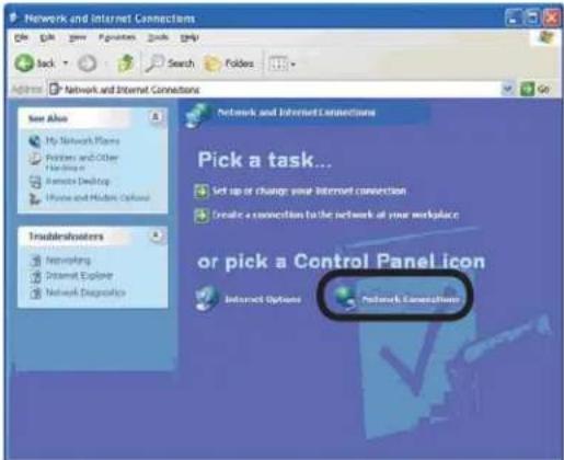
Fig. 2.3.2.a "Network and Internet Connections" window
4) Open "Network Connections". (Fig.2.3.2.b)
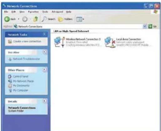
Fig. 2.3.2.b "Network Connections" window
2.3 Manual network connection setting - Wired LAN - (continued)
5) Open "Local Area Connection Properties" window you use for network device. (Fig. 2.3.2.c)
![Local Area Connection Properties General Authentication Advanced Connect using: Intel(R) PRO/1000 MT Mobile Connection Configure... The connection uses the following items: ✓ Network Monitor Driver ✓ AEGIS Protocol (IEEE 802.1x v2.3.1.9 ✓ Internet Protocol [TCP/IP] Install... Uninstall Properties Description Transmission Control Protocol/Internet Protocol. The default wide area network protocol that provides communication across diverse interconnected networks. ✓ Show icon in notification area when connected OK Cancel](/content/2026/05/843273/images/a1383247890a0393184ae18a0cdd9324cf2380f283fd1a8b094c4027d2c1e3ef.jpg)
Fig. 2.3.2.c "Local Area Connection Properties" window
6) Set used protocol as "TCP/IP" and open "Internet Protocol (TCP/IP) Properties" window.
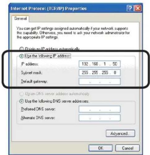
Fig. 2.3.2.d "Internet Protocol (TCP/IP) Properties" window
7) Set IP address, subnet mask and default gateway for PC.
2.3 Manual network connection setting - Wired LAN - (continued)
[About IP address]
■ Setting manually
The Network address portion included in the IP address set into your PC should be common with projector's one. And the entire IP address in the PC should not be overlapped with other equipments in the same network, including the projector.
For example
The projector's initial settings are as follows.
IP address: 192.168.1.10
Subnet mask: 255.255.255.0
(Network address: 192.168.1 in this case)
Therefore, specify PC's IP address as follows.
IP address: 192.168.1.xxx (xxx shows decimal number.)
Subnet mask: 255.255.255.0
(Network address: 192.168.1 in this case)
Select from 1 to 254 for “xxx” not duplicating with any other equipments. In this case, projector has “192.168.1.10” IP address, specify from 1 to 254 except 10 for PC.
NOTE • “0.0.0.0” cannot be set to the IP address.
- The projector's IP address can be changed by using the configuration utility via a web browser. (65)
- If the projector and PC exist in the same network (i.e. network address is common), default gateway can be blank.
- When the projector and PC exist in different networks, default gateway setting is necessary. Contact the network administrator in detail.
■ Setting automatically
When DHCP server exists in network, it is possible to assign IP address to the projector and PC automatically.
* DHCP is abbreviation for “Dynamic Host Configuration Protocol” and has the function to provide necessary setting for network like IP address from server to client. A server that has DHCP function is called DHCP server.
2.3 Manual network connection setting - Wired LAN - (continued)
2.3.3 "Internet Option" setting
1) Click "Internet Options" in "Network and Internet Connections" window (Fig. 2.3.3.a) to open "Internet Properties" window. (Fig.2.3.3.b)
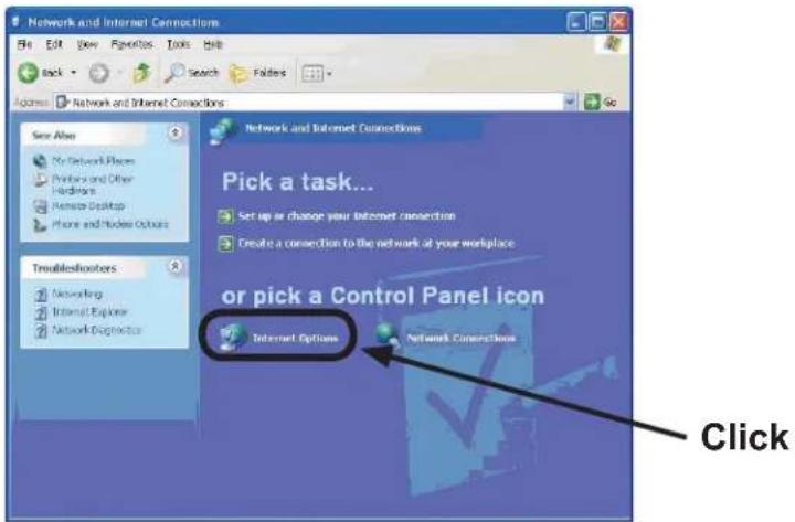
Fig. 2.3.3.a "Network and Internet Connections" window
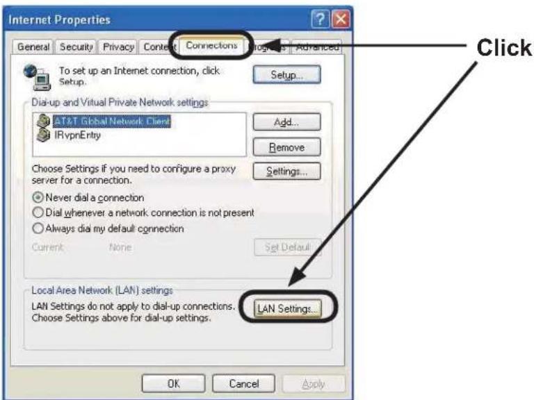
Fig. 2.3.3.b "Internet Properties" window
2) Click "Connections" tab and then click [LAN Settings] button to open "Local Area Network (LAN) settings". (Fig. 2.3.3.c)
2.3 Manual network connection setting - Wired LAN - (continued)
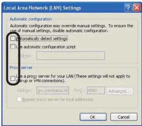
Fig. 2.3.3.c "Local Area Network (LAN) Settings" window
3) Uncheck all boxes in "Local Area Network (LAN) Settings" window. (Fig. 2.3.3.c)
2.3.4 Check connection
Check PC and projector are connected properly here. If it is not connected, check cable connections and settings are properly or not.
1) Start browser in PC and specify following URL, then click “→” button. URL: http://(Projector IP address)/
For example, if projector IP address is 192.168.1.10, specify URL: http://192.168.1.10/
2) If Fig. 2.3.4 appears, it succeeds.
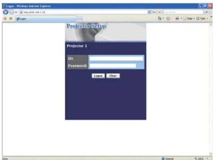
Fig. 2.3.4 "Logon menu"
2.4 Manual network connection setting -Wireless LAN
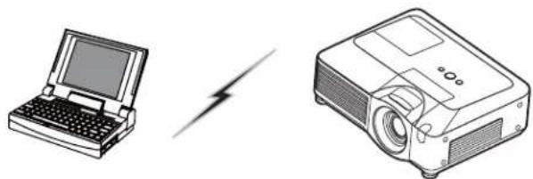
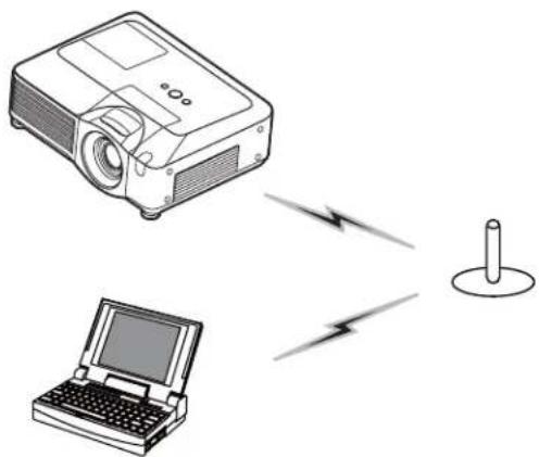
The projector and PC can communicate in both of Ad-Hoc and Infrastructure modes, using the designated wireless network card (option) on the projector. This section is intended to explain how to set up wireless LAN connection manually.
2.4.1 Preparation for wireless LAN connection
natural_image
Illustration of a laptop and a projector with a lightning bolt symbol (no text or labels)Fig. 2.4.1.a Without an access point communication (Ad-Hoc)
natural_image
Illustration of a projector and a laptop connected via wireless signal lines to a cylindrical device (no text or symbols)Fig. 2.4.1.b With an access point communication (Infrastructure)
* Ad-Hoc is one of the wireless LAN communication methods without having access point to communicate.
* Infrastructure is one of the wireless LAN communication methods with having access point to communicate. If certain quantities of equipments are used, this mode is efficient.
If communicating with existing network, contact your network administrator.
First, insert the wireless network card into SD card slot (Using an SD card of the Operator's Guide).
Then, make PC ready for wireless communication.
In case IEEE802.11b/g wireless LAN device is built-in the PC, make it valid and make other network connections invalid. If wireless LAN device is not built-in the PC, connect IEEE802.11b/g wireless LAN device and install device driver. (Refer to the user guide for PC and wireless LAN device for detail.)
2.4 Manual network connection setting -Wireless LAN (continued)
2.4.2 Wireless LAN connection set up
Using wireless LAN utility for Windows ^® XP standard. Wireless LAN initial settings for the projector is as follows.
Connection Control : Ad-Hoc
SSID : wireless
Channel : 1ch
Encryption rating : None
Communication speed : AUTO
IP address : 192.168.1.10
* You can change these settings as you want via a web browser on your PC or the menu on the projector. Refer to the item 4.1.3 Network Settings (69) or
MIU menu in the Operator's Guide.
1) Open "Network Connections". (Fig. 2.4.2.a)
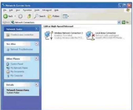
Fig. 2.4.2.a "Network Connections"
2) Open "Wireless Network Connection Properties". (Fig. 2.4.2.b)
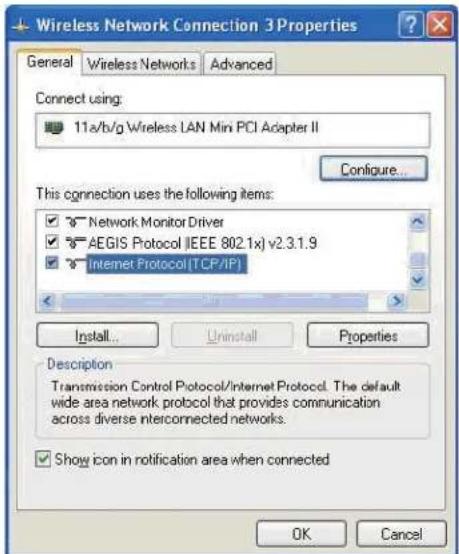
Fig. 2.4.2.b "Wireless Network Connection Properties" window (1)
2.4 Manual network connection setting -Wireless LAN (continued)
3) Set used protocol as "TCP/IP" and open TCP/IP property. Set IP address and other settings as same as wired LAN connection set up. (12)
4) Open "Wireless Networks" tab. (Fig. 2.4.2.c)
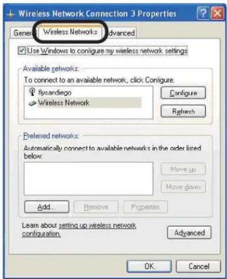
Fig. 2.4.2.c "Wireless Network Connection Properties" window (2)
5) Add check mark for "Use Windows to configure my wireless network settings" in "Wireless Network Connection Properties" window.
6) Click [Add] button in "Preferred networks" section in "Wireless Network Connection Properties" window (Fig. 2.4.2.c) to open "Wireless network properties" window. (Fig. 2.4.2.d)
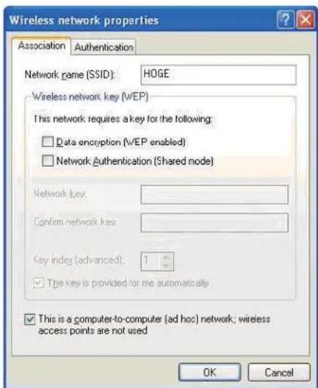
Fig. 2.4.2.d "Wireless network properties" window
2.4 Manual network connection setting -Wireless LAN (continued)
7) Set each item as follows.
Network name (SSID): wireless
Data encryption: not enabled (Default setting is not enabled.)
NOTE • If the default setting in the projector is used, set the data as above into your PC. If an access point is used or any encryption mode is used, it is required to set the data that is matched to your system.
Refer to the manuals for your PC or wireless LAN adapter or access point.
- If you want to use the existing network via an access point, contact your network administrator before the connection.
3. Using the Live Mode
3. Using the Live Mode
The section is intended to explain the process to use the projector in the Live Mode.
The outline of the process is as follows.
1) Install "Live Viewer 3" (23)
2) Quick Connection to the network (26)
The Quick Connection feature prepares some options to connect your network. You can select one that meets your requirement.
- Passcode connection
- Profile data connection
- History record connection
- My Connection
- Manual connection
3) Confirm the connection to your destination (50)
In some case, there are several projectors connected to the same network. Before you send your image, confirm that the right projector is selected.
4) Start the "Live Viewer 3" (54)
The "Live Viewer 3" main menu will be on screen.
Now, you can send your images to the projector through the network.
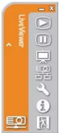
Fig. 3 "Live Viewer 3" Main menu
3.1 Outline of the Live Mode
The Live Mode can display PC's image on screen in real time through either wired or wireless LAN. So, no signal cable connection is required.
3.1.1 Display mode
In the Live Mode, there are two display modes, Single PC mode and Multi PC mode.
1) Single PC mode
The projector displays images sent by one PC.
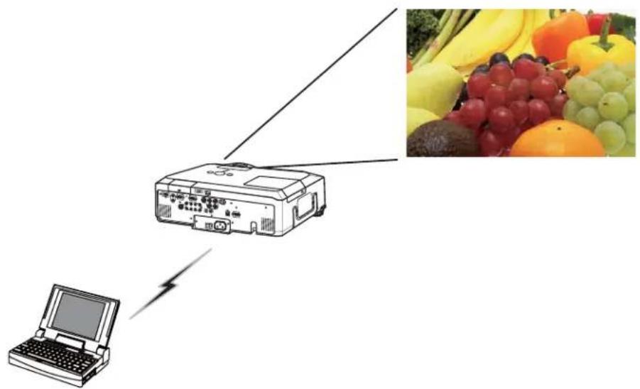
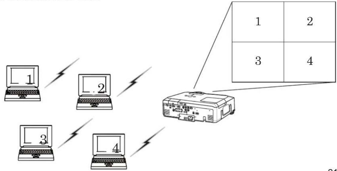
2) Multi PC mode
The projector screen is divided to 4 zones. The projector displays images in one zone sent by a PC, so that the projector can displays images sent by up to 4 PCs at the same time.
flowchart
graph TD
    A["1"] --> B["2"]
    C["3"] --> D["4"]
    E["4"] --> F["Printer"]
    style A fill:#f9f,stroke:#333
    style C fill:#f9f,stroke:#333
    style E fill:#f9f,stroke:#333
    style F fill:#ccf,stroke:#333
3.1 Outline of the Live Mode (continued)
3.1.2 Presenter mode
In the Single PC mode, the projector can be occupied by one PC and can block an access from any other PC, if the Presenter mode is selected in the “Live Viewer 3”.
While making your presentation, you don't need to worry that the image on screen is unexpectedly switched to an image sent by another PC.
The Presenter mode can be set on the Option menu in the "Live Viewer 3" main menu. (58)
3.1.3 Display User Name
A "User Name" can be input in the "Live Viewer 3", which is displayed on screen by operating the menu on the projector. So, it can be found out whose image is currently displayed on screen. (58)
3.2 Install "Live Viewer 3"
In order to use the Live Mode and Quick connection, you need to install the enclosed software, the “Live Viewer 3”, into all PCs that you want to connect to the projector through the network.
3.2.1 Minimum PC hardware and software requirement
- OS: Windows
® 2000 Professional (Service Pack4)
Windows® XP Home Edition
Windows® XP Professional
Windows® Vista Home Basic (32bit)
Windows® Vista Home Premium (32bit)
Windows® Vista Business (32bit)
Windows® Vista Enterprise (32bit)
Windows® Vista Ultimate (32bit)
- Graphic Interface: Video RAM 4MB or higher (8MB recommended)
- CPU: Pentium ^ III (600MHz or higher recommended)
- Display: VGA 640x480 or higher (XGA 1024x768 recommended)
65,536 simultaneous colors or higher
NOTE • Set your PC's resolution to XGA or less. Refer to the user manual for your PC or Windows.
- In some cases, your PC's screen will not be displayed correctly by the projector. If the resolution is larger than 1024x768, the projector can display only the 1024x768 portion of the image.
- Images might not been transmitted, caused by OS version or the driver software for Network Adapter on your PCs. It is highly recommended that OS and the driver should be updated to the latest.
• Memory: 64MB or higher (128MB or higher if using
Windows® XP)
• Available Hard Disk Space: 20MB or higher
- Web browser: Internet Explorer ^ (5.5 or higher)
- CD-ROM drive
• Wireless: IEEE802.11b/g
NOTE • Depending on the type of wireless network device and PC you are using, the projector may not be able to communicate properly with your PC, even if the PC you are using is equipped with built-in wireless LAN functionality. If the communication problems occur, please use a Wi-Fi certified wireless network device.
3. Using the Live Mode
3.2 Install "Live Viewer 3" (continued)
3.2.2 Software Installation Procedure
1) Turn on the PC.
2) Shut down all applications.
3) Insert the accompanying CD-ROM into the PC's CD-ROM drive.
NOTE • After sequence 3, the User Account Control (UAC) dialog will appear (if you are using Windows® Vista). Please click [Allow] to continue installation.
4) After a moment, the Choose Setup Language dialog will appear as shown on the right. Select what you like to use in the list, and click [OK].
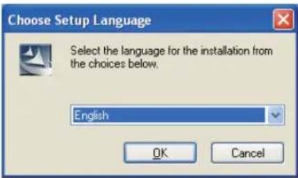
NOTE • If the Welcome dialog doesn't appear, proceed as follows:
(1) Click on the [Start] button on the toolbar and select the "Run".
(2) Enter E:\software\setup.exe and then press [OK].
If your CD-ROM drive is not drive E on your PC, you will need to replace E with the correct drive letter assigned to your CD-ROM drive.

If the software has been already installed, Uninstallation will be done. Click [Cancel] button, then uninstallation will be canceled. If you uninstalled the software by miss-operation, please re-install the software from first procedure.
5) After a moment, the Welcome dialog will appear as shown on the right. Press [Next].
6) The License Agreement dialog appears. If you accept it, select "I accept the terms of the license agreement" and press [Next].
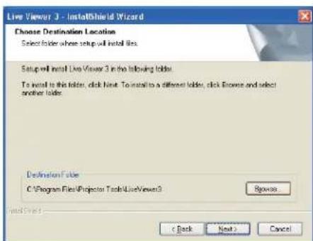
7) The Choose Destination Location dialog appears. Press [Next].
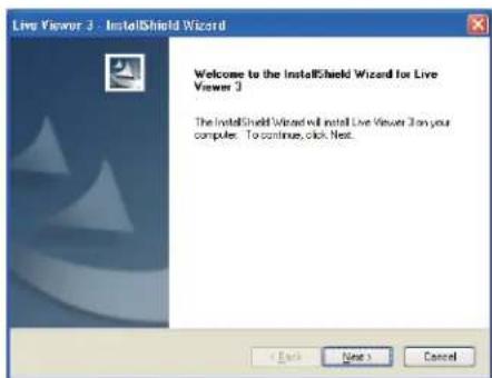
NOTE • The C:\Program Files\Projector Tools\LiveViewer3 folder will be created and the program will be installed into that folder. If you wish to install to a different folder, click [Browse] and select another folder.
3.2 Install "Live Viewer 3" (continued)
8) Confirm the program folder name. If "Projector Tools" is okay, press [Next] to continue. If not, enter the desired folder name and then press [Next].
9) The Hardware Installation dialog appears. Press Continue Anyway.
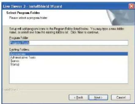
NOTE • After sequence 8, the Windows Security dialog will appear if you are using Windows® Vista. Please click the [Install this driver software anyway] and continue installation.
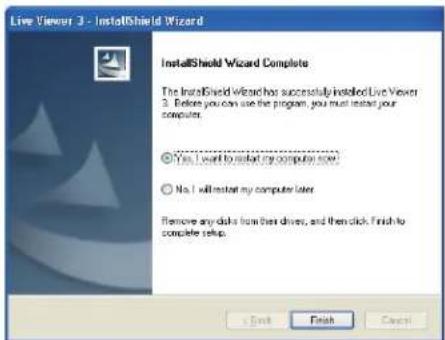
10) After a moment, installation will complete and the Setup Complete dialog will appear as shown on the right. Click [Finish]. This completes the software installation. Then your PC automatically restarts.
(1) To confirm that the software has been properly installed, press [Start] button on the toolbar, select All Programs and then select the Projector Tools folder.
(2) The "LiveViewer3" will appear in that folder if the installation was successful.
3.2.3 Version of the "Live Viewer" software
To use the Live Mode, it is required to install the software, the "Live Viewer", into the PC that is going to be connected to the projector through the network. The right software version is depended on the models that you have. If the version is not matched with the projector, the software will not work properly.
| Live Viewer Version | Models | |
| X62wX90w | X64wX95X95i | |
| 2.1x | ○ | × |
| 2.20 | ○ | × |
| 3.xx | ○ | ○ |
- “x” in the version means 0 or greater.
Please check and get the latest version at 3M Web site. http://www.3m.com/meetings
3.3 Quick connection to the network
The Live Mode prepares some options for the network connection. You can choose one that meets to your system.
The explanation here is based on the case that Windows ^® XP is installed in your PC.
3.3.1 Starting the "Live Viewer 3"
Start the "Live Viewer 3" in your PC, taking one of the followings.
1) Double click the "Live Viewer 3" icon on the Desktop in your PC
2) Select "Start" → "All Programs" → "Projector Tools" → "Live Viewer 3" on Windows® XP menu.
Then, proceed to the item 3.3.2 Selecting the connection mode. (

[trouble shooting]
In order to display the computer image correctly, you will need to change the screen resolution.
If the resolution on your PC is set higher than XGA (1024x768), the screen is displayed.
To change the resolution, click [Yes]. Not to change the resolution, click [No].
If you click [Yes], the resolution on your PC is switched to XGA (1024x768).
If you click [No], the resolution is not changed.
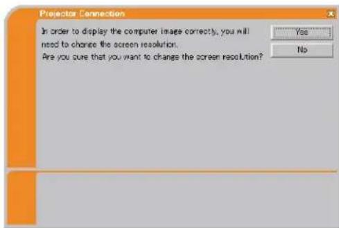
NOTE • When the resolution is changed, the arrangement of icons on PC Desktop screen may be changed.
- Even if the resolution is changed, it will be back to the original when the "Live Viewer 3" is closed.
- If the resolution is not changed, the projector will display XGA(1024x768) portion from top left corner of your PC screen.
- Refer to the user manual for your PC or Windows to change the resolution.
3.3 Quick connection to the network (continued)
3.3.2 Selecting the network connection mode
After starting the "Live Viewer 3", the "Select the Network Connection" screen comes up. Select the network connection that you would like to use. There are 3 options in the menu.
- Wireless LAN
- Wired LAN
- My Connection
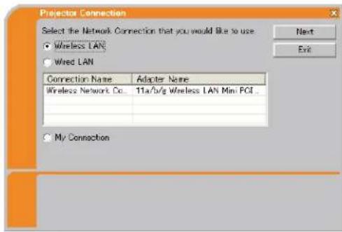
If you select either the wireless LAN or wired LAN, proceed to the Selecting either the wireless LAN or wired LAN (below).
If you select the My Connection, jump to the Selecting the My Connection. (29)
Selecting either the wireless LAN or wired LAN
If you select either the wireless LAN or wired LAN, a list of the network adapters in your PC is shown in the menu.
Select what you like to use in the list, and click [Next].
Then, proceed to the item 3.3.3 Connecting to the network. (31)
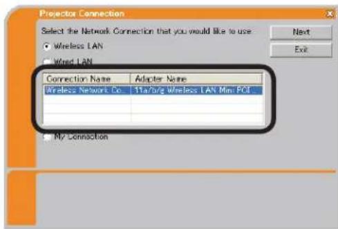
NOTE • If you select the wireless LAN, the wireless LAN adapters in your PC are shown in the list.
- If the wired LAN is selected, the wired LAN adapters in your PC are shown.
[trouble shooting]
■ Are you sure that you want to turn on the network adapter?
The screen is displayed in the case that the selected network adapter is invalid.
- To turn it on, click [Yes], and then proceed to the item 3.3.3 (31).
- Not to turn it on, click [No], and then the screen is back to the previous one to select another network adapter. If no more adapter in your PC, the "Live Viewer 3" will be closed.
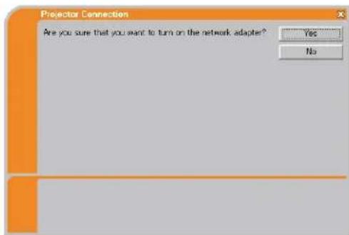
3. Using the Live Mode
3.3 Quick connection to the network (continued)
■ A network connection was not established.
The screen is displayed in the case that the projector is not connected with a LAN cable to your PC when the wired LAN is selected.
Be sure that the projector is connected with a LAN cable to your PC.
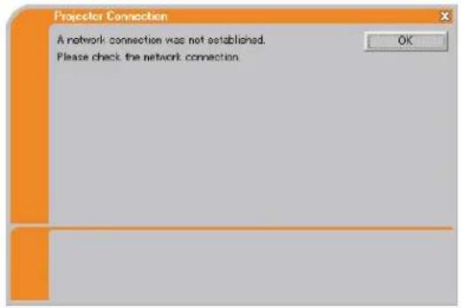
Click [OK], then the screen is back to the previous one to select the network connection mode.
■ Windows firewall is enabled(On).
The screen is displayed in the case that the firewall setting in Windows® XP/Vista is activated, and the "Live Viewer 3" is blocked by the firewall.
- To turn it disabled(Off), click [Yes].
- Not to turn it disabled(Off), click [No], but the projector may not be able to communicate with your PC through the network.
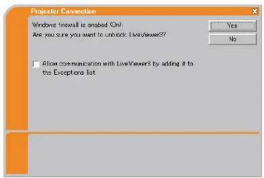
- If you put a check mark in the [Allow communication with LiveView3 by adding it to the Exceptions list] box, the "Live Viewer 3" will never be blocked by Windows firewall.
Proceed to the item 3.3.3 Connecting to the network. (31)
NOTE • If you click [Yes], the network access by the "Live Viewer 3" is temporally permitted by Windows firewall, until the "Live Viewer 3" is closed. • If any application software having the firewall function is installed into you PC, make the firewall function invalid with following the user's manual.
3.3 Quick connection to the network (continued)
Selecting the My Connection
Select [My Connection] and click [Connect].
If you select the My Connection, the PC is connected to the projector through the network by using the profile data that is pre-assigned to My Connection. (62) When you select the My Connection, the PC immediately starts the connection to the projector.
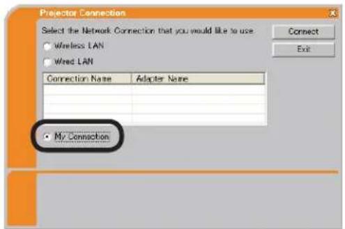
Proceed to the item 3.6 Confirm the connection to your destination. (50)
NOTE • If the DHCP is set on in the projector, the network connection between the projector and PC may not be established since IP address may be varied. If you like to use the My Connection, set the DHCP off in the projector. • If no profile data is assigned to the My Connection, it can't be used.
[trouble shooting]
■ A network connection could not be established.
Windows prevented network configuration changes.
You may log in the Windows under User authority.
Click [OK] to return to the screen to select the network connection mode. (27)
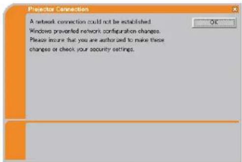
Consult to the network administrator and log in again under the Administrator authority. After that, please resume at the item 3.3.1 Starting the “Live Viewer 3”. (26)
3. Using the Live Mode
3.3 Quick connection to the network (continued)
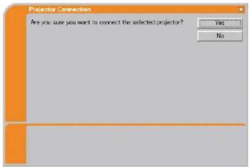
■ Are you sure you want to connect the selected projector?
The message is appeared when the wireless adapter you selected is already used for another network connection.
- To connect, click [Yes]. Proceed to the 3.6 Confirm the connection to your destination. (50)
- Not to connect, click [No] to return to the screen to select the network connection mode. (27)
3.3 Quick connection to the network (continued)
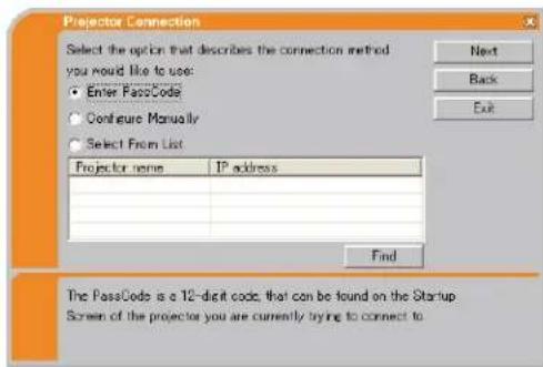
3.3.3 Connecting to the network
There are some options to connect to the network.
- Enter PassCode
- Configure Manually
- Select From List
Select one of them to meet your requirement.
Enter PassCode
If you want to use the Passcode for network connection, select [Enter PassCode] and click [Next].
The Passcode is given by the projector on screen. And you simply input the Passcode to the "Live Viewer 3" to connect the network.
Proceed to the 3.4 Passcode connection. (32)
Configure Manually
Select [Configure Manually] and click [Next].
Then, there are 3 options on the manual connection method.
- Profile Proceed to the 3.5.1 Profile connection (41)
You just select one of the stored profile data to connect the network.
• History Proceed to the item 3.5.2 History connection (42)
Once connecting to the network, the "Live Viewer 3" stores the history. If you need the same connection again, select [History].
Then, all you need to do is to select one of the history data from the list.
- Configure Network Settings Manually Proceed to the item
3.5.3 Configuring manually (43)
If you need to make the setting manually, select [Configure Network Settings Manually].
Select From List
Before selecting this item, your PC and the projectors need to be connected to the same network.
If the connection is already established, select [Select From List].
From the list of the projectors connected to the network, select which projector you would like to send your images. Proceed to the 3.6 Confirm the connection to your destination. (50)
3.4 Passcode connection
The unique Passcode system brings you very quick and simple connection to the network.
The Passcode is a code that expresses the network setting in the projector. If you input the code in the “Live Viewer 3” in your PC, the network setting in the projector and PC can be matched and the connection will be established immediately.
The section is intended to explain how to use the Passcode.
3.4.1 Getting the Passcode
The Passcode is 12-digit code consisting of alphanumeric characters (“1-9” and “A-Z”).
Example: PASSCODE 1234-5678-9ABC
The Passcode is given on the projector screen.
NOTE • The Passcode system does not work under the condition below. If your system meets one of them, set the connection manually.
1) Any encryption code is used. The Passcode system does not work with an encryption code.
2) Unique SSID is used. The Passcode system accepts the factory default SSID only.
Factory default SSID 1 : wireless
Factory default SSID 2 : WLANProjector1
Factory default SSID 3 : WLANProjector2
Factory default SSID 4 : WLANProjector3
3) Subnet mask is not Class A or B or C. The Passcode system accepts Class A, B and C only. Class A:(255.0.0.0), ClassB:(255.255.0.0), Class C:(255.255.255.0)
There are two methods to get the Passcode from the projector
Method 1
1) Turn on the projector, and make sure that the projector image is on screen.
2) Press theRGB button on the remote control or INPUT button on the projector to select the MIU as input port.
If there is no signal on the MIU port you can find the Passcode on screen, otherwise proceed to 3) below.
3) Press theMENU button on the remote control or the ▲/▼/◄/► buttons on the projector to show the menu on screen.
4) Use the ▲/▼ cursor buttons to select the Advanced Menu, and use the ▶ cursor button to enter the item.
5) Use the ▲/▼ cursor buttons to select the MIU, and use the ▶ cursor button to enter the item.
6) Use the ▲/▼ cursor buttons to select the LIVE MODE, and push the ▶ cursor button.
7) The Passcode is appeared on the screen.
3.4 Passcode connection (continued)
Method 2
1) Turn on the projector, and make sure that the projector image is on screen.
2) Press theMENU button on the remote control or the ▲/▼/◄/► buttons on the projector to show the menu on screen.
3) Use the ▲/▼ cursor buttons to select the Advanced Menu, and use the ▶ cursor button to enter the item.
4) Use the ▲/▼ cursor buttons to select the MIU, and use the ▶ cursor button to enter the item.
5) Use the ▲/▼ cursor buttons to select the INFORMATION, and use the ▶ cursor button to display the INFORMATION.
6) The Passcode is appeared at the top right corner in the INFORMATION window.
NOTE • Take the Method 2, when you use the projector in the LIVE MODE or PC-LESS Presentation mode, or when the MIU is not selected as the input signal.
- If no communication between the projector and PC in 5 minutes, the Passcode will be changed.
3.4 Passcode connection (continued)
3.4.2 Entering the Passcode
If you select [Enter PassCode] at the item 3.3.3, the "Please enter the PassCode" screen is displayed. Please enter the Passcode divided 4-digit each in 3 boxes (total 12-digit).
Example PASSCODE: 1234 - 5678 - 9ABC
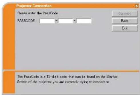
After entering the Passcode, click [Connect] to start the connection to the projector.
Proceed to the item 3.6 Confirm the connection to your destination. (50)
If you click [Back], the screen is back to the item 3.3.3 Connecting to the network. (31)
NOTE • When entering the Passcode, capital and small letters are not distinguished.
- If you are using any encryption code or your unique SSID or Subnet mask excluding ClassA and B and C, it is required to set the connection manually. If the manual setting screen is displayed, please follow the item 3.4.3.
[trouble shooting]
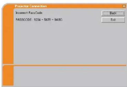
■ Incorrect PassCode.
The incorrect Passcode was input.
Click [Back] to return to the "Please enter the PassCode" screen.
Check the PassCode on the projector screen (32) and enter the code again.
3.4 Passcode connection (continued)
■ A network connection could not be established.
Windows prevented network configuration changes.
You may log in the Windows under User authority.
Click [OK], then the "Live Viewer 3" main menu is displayed even though the network is not established. Click 📄 on the main and go back to the item 3.3.3 Connecting to the network. (31)
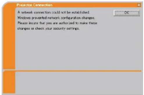
Consult to the network administrator. Log in the Windows under Administrator authority. After that, please resume at the item 3.3.1 Starting the “Live Viewer 3”. (26)
■ Automatic connection failed.
The reason is that the IP address set in the projector is the global address.
Following the instruction by the network administrator, set the IP address and Subnet mask in the "Live Viewer 3".
After input these address, click [Connect].
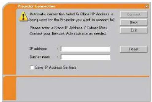
If you want to erase the information you input, click [Reset].
NOTE • If the IP address you input to the PC is the same as the one set in the projector, a warning message will come up. Please choose an IP address that is currently not in use.
3. Using the Live Mode
3.4 Passcode connection (continued)
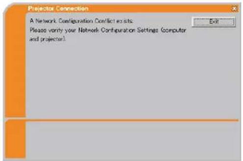
■ A Network Configuration Conflict exists.
The message comes up when the network connection mode you set in the PC does not match with the mode of the projector.
Please verify your network configuration setting on the projector and PC.
Click [Exit], then the "Live Viewer 3" main menu is displayed even though the network is not established. Click 📄 on the main menu to go back to the item 3.3.3 Connecting to the network. (📖31)
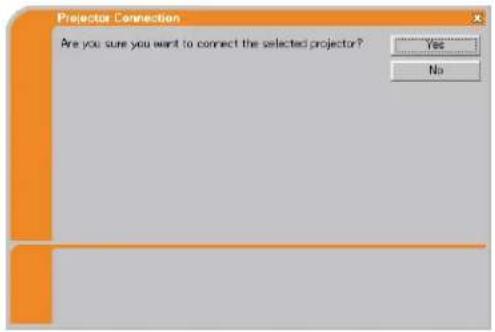
■ Are you sure you want to connect the selected projector?
The message is appeared when the wireless adapter you selected is already used for another network connection.
- To connect, click [Yes]. Proceed to the 3.6 Confirm the connection to your destination. (50)
- Not to connect, click [No] then the "Live Viewer 3" main menu is displayed even though the network is not established. Click on the main menu to go back to the item 3.3.3 Connecting to the network. (31)
3.4 Passcode connection (continued)
3.4.3 Configuring manually
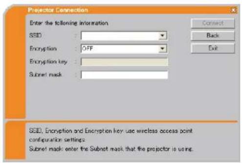
After you input the Passcode (34), you are required to input the network setting manually if you use any encryption code or your unique SSID or Subnet mask except Class A/B/C. (32)
If you use the wired LAN, go to (40).
Wireless LAN
The required information depends on how you connect the projector and PC.
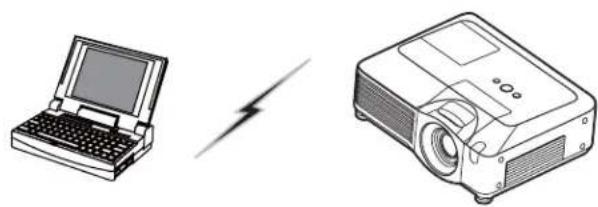
- Direct connection between the projector and PC (AdHoc mode)
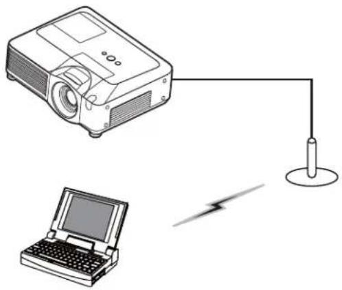
- The projector connected to an access point by a LAN cable
- The projector connected to an access point by the wireless LAN
Direct connection between the projector and PC (AdHoc mode)
natural_image
Illustration of a laptop and a projector with a lightning bolt symbol (no text or labels)1) Enter the following information that is set in the projector. *1
SSID *2: wireless (example)
Encryption: WEP64bit (example)
Encryption key *3: ***** (example)
Subnet mask *4: 255.255.255.128
(example)
2) Click [Connect].
3) The wireless connection will be established.
Proceed to the item 3.6 Confirm the connection to your destination. (50)
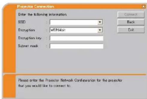
*1 To find the network setting on the projector, refer to the NOTE. (40)
*2 If you don't use the factory default SSID, you need to set your SSID by either entering manually or selecting from the list of detected SSID.
*3 If you use an encryption, you need to set it. Contact the network administrator to find the encryption key that is set in the projector.
The encryption key is always shown as “**********”.
*4 If you use Subnet mask except Class A/B/C, please set it.
3.4 Passcode connection (continued)
The projector connected to an access point by a LAN cable
natural_image
Illustration of a projector connected to a laptop and a power cord (no text or symbols)1) The setting on the access point. *1
Enter the following information.
SSID : WirelessAccessPoint (example)
Encryption: WEP64bit (example)
Encryption key *2: ********** (example)
2) The setting on the projector. *3
Enter the following information.
Subnet mask *4: 255.255.255.128
(example)
3) Click [Connect].
4) The wireless connection will be established.
Proceed to the item 3.6 Confirm the connection to your destination. (50)
*1 Contact the network administrator to find out the setting on the access point.
*2 If you use an encryption, you need to set it. Contact the network administrator to check the encryption key that is set in the projector.
The encryption key is always shown as “**********”.
*3 To find the network setting on the projector, refer to the NOTE. (40)
*4 If you use Subnet mask except Class A/B/C, please set it.
3.4 Passcode connection (continued)
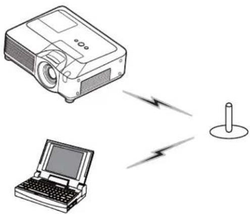
The projector connected to an access point by the wireless LAN
natural_image
Illustration of a projector and a laptop connected via wireless signal lines to a cylindrical device (no text or symbols)1) Enter the following information that is set in the projector. *1
SSID *2: wireless (example)
Encryption: WEP64bit (example)
Encryption key *3: ********** (example)
Subnet mask *4: 255.255.255.128
(example)
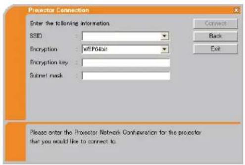
2) Click [Connect].
3) The wireless connection will be established.
Proceed to the item 3.6 Confirm the connection to your destination. (50)
*1 To find the network setting on the projector, refer to the NOTE. (40)
*2 If you don't use the factory default SSID, you need to set your SSID by either entering manually or selecting from the list of detected SSID.
*3 If you use an encryption, you need to set it. Contact the network administrator to find the encryption key that is set in the projector.
The encryption key is always shown as “**********”.
*4 If you use Subnet mask except Class A/B/C, please set it.
3. Using the Live Mode
3.4 Passcode connection (continued)
Wired LAN
1) Enter the following information for the projector.
Subnet mask *1: 255.255.255.128 (example)
2) Click [Connect].
3) The network connection will be established. Proceed to the item 3.6 Confirm the connection to your destination. (50)
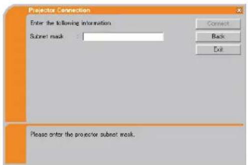
*1 In case the case you use the Subnet mask except Class A/B/C, the screen is appeared. Please set the Subnet mask.
NOTE • If you require the network setting information on the projector, take the following procedure to find it out.
1) Turn on the projector, and make sure that the projector image is on screen.
2) Press theMENU button on the remote control or the ▲/▼/◄/► buttons on the projector to show the menu on screen.
3) Use the ▲/▼ cursor buttons to select the Advanced Menu, and use the ▶ cursor button to enter the item.
4) Use the ▲/▼ cursor buttons to select the MIU, and use the ▶ cursor button to enter the item.
5) Use the ▲/▼ cursor buttons to select the INFORMATION, and push the ▶ cursor button.
6) The setting will be displayed in the MIU-INFORMATION-box.
3.5 Manual configuration
There are 3 options for the manual configuration.
- Profile (below)
• History (42) - Configure Network Settings Manually (43)
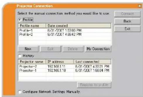
3.5.1 Profile connection
Selecting a profile data connect the network with the projector.
It is required to store the profile data in advance. (60)
1) Select [Profile].
2) Choose a profile data listed in the window.
3) Click [Connect].
4) The network connection will be established.
Proceed to the item 3.6 Confirm the connection to your destination. (50)
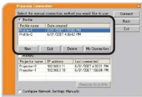
NOTE • To check the setting in a profile data, follow the process below.
1) Choose a profile data that you want to check.
2) Move the mouse cursor to the profile data, and click the right button on the mouse to display a pop-up menu.
3) Select the "Property" in the pop-up menu, and click the left button on the mouse.
4) The setting information of the selected profile data is shown.
- If the DHCP is set on in the projector, the network connection between the projector and PC may not be established since IP address may be varied. If you like to use the Profile connection, set the DHCP off in the projector.
3.5 Manual configuration (continued)
3.5.2 History connection
The "Live Viewer 3" can memory the network settings when connecting to the projector as a history record. After that, selecting a history record can quickly connect the network with the projector.
1) Select [History].
2) Choose a history record listed in the window.
3) Click [Connect].
4) The network connection will be established.
Proceed to the item 3.6 Confirm the connection to your destination. (50)
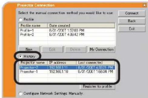
If you want to copy a history record to a profile data, select one of the history record and click [Register to profile]. The profile data cannot be erased automatically.
NOTE • The number of the history record is maximum 10 for each network adapter. When the 11th data is stored, the oldest record among the 10 will be overwritten.
- The data & time information in each history record is renewed when the network is connected by using the history record.
- If the DHCP is set on in the projector, the network connection between the projector and PC may not be established since IP address may be varied.
- Even if you use the profile connection, it will be memorized as a history record.
3.5 Manual configuration (continued)
3.5.3 Configuring manually
All setting for the network connection between the projector and PC is input manually.
Select [Configure Network Settings Manually].
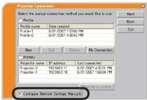
The information to be input manually is different, depending on how you want to connect the projector and PC.
Wireless LAN
The required information depends on how you connect the projector and PC.
- Direct connection between the projector and PC (AdHoc mode). (44)
• The projector connected to an access point by a LAN cable. (45)
• The projector connected to an access point by the wireless LAN. (46)
Wired LAN
If you use the wired LAN, go to (47).
3. Using the Live Mode
3.5 Manual configuration (continued)
Direct connection between the projector and PC (AdHoc mode)
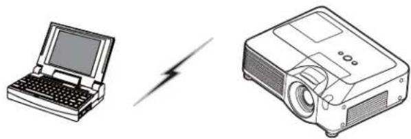
natural_image
Illustration of a laptop and a projector with a lightning bolt symbol (no text or labels)1) Enter the following information that is set in the projector. *1
SSID: wireless (example)
Encryption: WEP64bit (example)
Encryption key *2: ********** (example)
Mode: AD-HOC
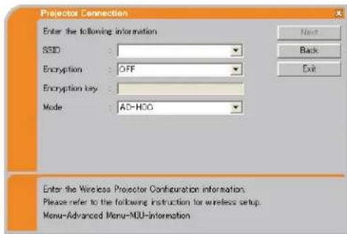
2) Click [Next].
3) Enter the following information that is set in the projector. *1
IP address : 192.168.1.10 (example)
Subnet mask: 255.255.255.0 (example)
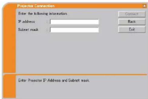
4) Click [Connect].
5) The wireless connection will be established.
Proceed to the item 3.6 Confirm the connection to your destination. (50)
*1 To find the network setting on the projector, refer to the NOTE. (40)
*2 If you use an encryption, you need to set it. Contact the network administrator to find the encryption key that is set in the projector.
The encryption key is always shown as “**********”.
3.5 Manual configuration (continued)
The projector connected to an access point by a LAN cable
natural_image
Diagram showing a projector connected to a laptop via a power cord, with a lightning bolt symbol nearby (no text or labels)1) The setting on the access point. *1
Enter the following information.
SSID: WirelessAccessPoint (example)
Encryption: WEP64bit (example)
Encryption key *2: ********** (example)
Mode: INFRASTRUCTURE
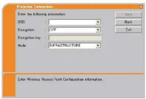
2) Click [Next].
3) Enter the following information that is set in the projector. *3
IP address : 192.168.1.10 (example)
Subnet mask: 255.255.255.0 (example)
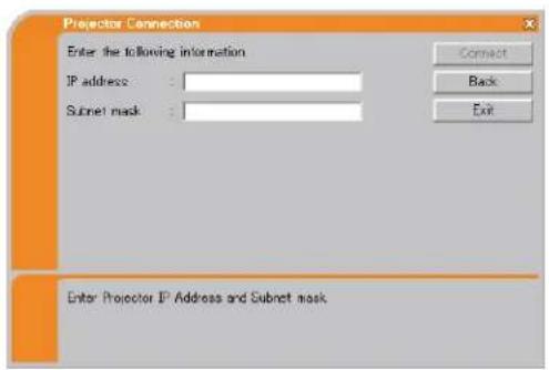
4) Click [Connect].
5) The wireless connection will be established.
Proceed to the item 3.6 Confirm the connection to your destination. (50)
*1 Contact the network administrator to find out the setting on the access point.
*2 If you use an encryption, you need to set it. Contact the network administrator to check the encryption key that is set in the projector.
The encryption key is always shown as "*******".
*3 To find the network setting on the projector, refer to the NOTE. (40)
3.5 Manual configuration (continued)
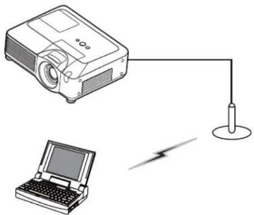
The projector connected to an access point by the wireless LAN
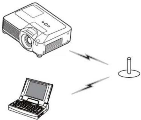
natural_image
Illustration of a projector and a laptop connected via wireless signal lines to a cylindrical device (no text or symbols)1) The setting on the access point. *1 Enter the following information.
SSID: WirelessAccessPoint (example)
Encryption: WEP64bit (example)
Encryption key *2: ********** (example)
Mode: INFRASTRUCTURE
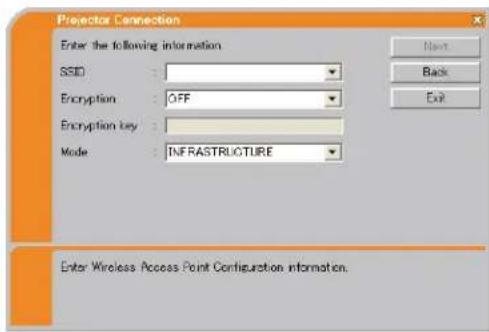
2) Click [Next].
3) Enter the following information that is set in the projector. *3
IP address : 192.168.1.10 (example)
Subnet mask: 255.255.255.0 (example)
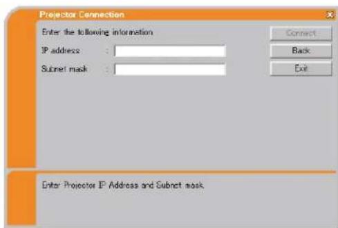
4) Click [Connect].
5) The wireless connection will be established.
Proceed to the item 3.6 Confirm the connection to your destination. (50)
*1 Contact the network administrator to find out the setting on the access point.
*2 If you use an encryption, you need to set it. Contact the network administrator to check the encryption key that is set in the projector.
The encryption key is always shown as “**********”.
*3 To find the network setting on the projector, refer to the NOTE. (40)
3.5 Manual configuration (continued)
Wired LAN
1) Enter the following information for the projector. *1
IP address : 192.168.1.10 (example)
Subnet mask : 255.255.255.0 (example)
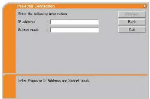
2) Click [Connect].
3) The network connection will be established.
Proceed to the item 3.6 Confirm the connection to your destination. (50)
*1 To find the network setting on the projector, refer to the NOTE. (40)
[trouble shooting]
■ A network connection could not be established.
Windows prevented network configuration changes.
You may log in the Windows under User authority.
Click [OK], then the "Live Viewer 3" main menu is displayed even though the network is not established. Click 📄 on the main menu and go back to the item 3.3.3 Connecting to the network. (📖31)
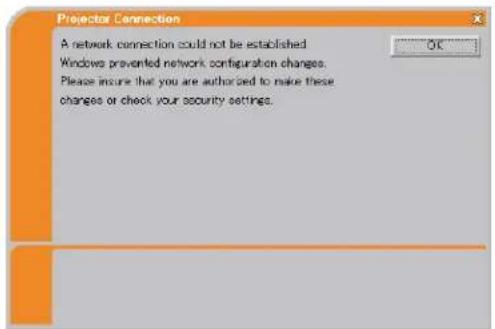
Consult to the network administrator. Log in the Windows under Administrator authority. After that, please resume at the item 3.3.1 Starting the “Live Viewer 3”. (26)
3. Using the Live Mode
3.5 Manual configuration (continued)
■ Automatic connection failed.
The reason is that the IP address set in the projector is the global address.
Following the instruction by the network administrator, set the IP address and Subnet mask in the "Live Viewer 3".
After input these address, click [Connect].
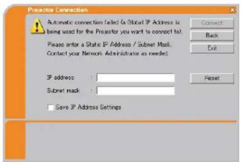
If you want to erase the information you input, click [Reset].
NOTE • If the IP address you input to the PC is the same as the one set in the projector, a warning message will come up. Please choose an IP address that is currently not in use.
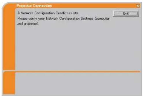
■ A Network Configuration Conflict exists.
The message comes up when the network connection mode you set in the PC does not match with the mode of the projector.
Please verify your network configuration setting on the projector and PC.
Click [Exit], then the "Live Viewer 3" main menu is displayed even though the network is not established. Click 📄 on the main menu to go back to the item 3.3.3 Connecting to the network. (📖31)
3.5 Manual configuration (continued)
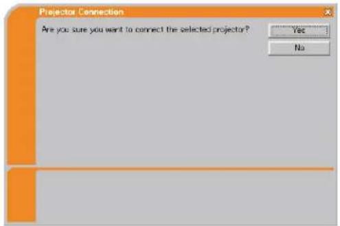
■ Are you sure you want to connect the selected projector?
The message is appeared when the wireless adapter you selected is already used for another network connection.
- To connect, click [Yes]. Proceed to the 3.6 Confirm the connection to your destination. (50)
- Not to connect, click [No] then the "Live Viewer 3" main menu is displayed even though the network is not established. Click 📄 on the main menu to go back to the item 3.3.3 Connecting to the network. (31)
3.6 Confirm the connection to your destination
3.6.1 Connection and transmission
When the network connection is established, the “Connection to Projector successful” screen is displayed.
Make sure that the right projector that you want to send your image to is selected, by checking the projector name and IP address shown in the screen.
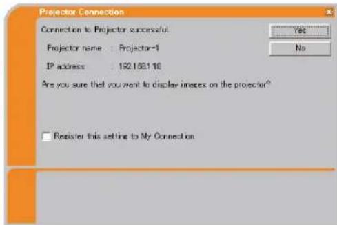
- To send images to the projector, click [Yes]. The transmission will be started. It is required to set the MIU as an input port and select the Live Mode in the MIU menu in the projector, to display the transmitted images.
Refer to the item 3.6.3 Setting the Live Mode. (53)
- Not to send, click [No], then the "Live Viewer 3" main menu is displayed in stand-by mode. (The stand-by mode is the condition that the wireless connection is established, but the images are not transmitted.)
The transmission can be started, if you click ▶ or □ button on the "Live Viewer 3" main menu.
If you wish to use the current connection setting as a profile data for My Connection, check in the box for [Register this setting to My Connection].
[trouble shooting]
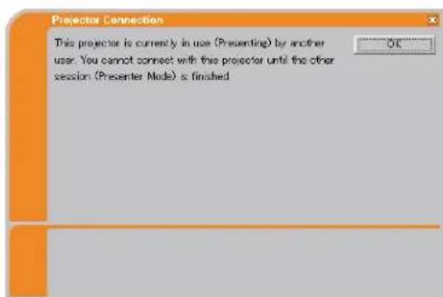
■ This projector is currently in use (Presenting) by another user.
The projector you want to send your images to is occupied by another computer in the Presenter mode.
Click [OK], then the "Live Viewer 3" main menu is displayed in stand-by mode. Retry to send your images, after the Presenter mode is off.
3.6 Confirm the connection to your destination (continued)
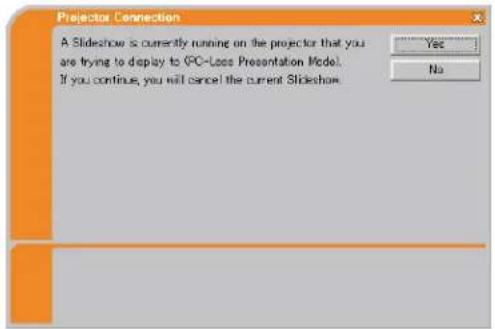
■ A Slideshow is currently running on the projector that you are trying to display to.
The projector you want to send your images to is in the Slide show mode in the PC-LESS Presentation.
- Click [Yes], then the projector is switched from the Slide show mode to the Live Mode.
- Click [No], then the projector is remained in the Slide show mode, and the "Live Viewer 3" main menu is displayed in stand-by mode on your PC.
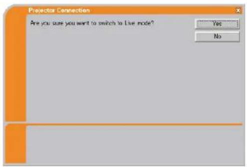
■ Are you sure you want to switch to Live Mode?
The projector is not set to the Live Mode.
- Click [Yes], then the projector is switched to the Live Mode.
- Click [No], then the projector is remained as it is, and the "Live Viewer 3" main menu is displayed in stand-by mode on your PC.
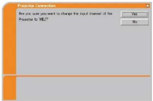
■ Are you sure you want to change the input channel of the Projector to MIU?
The projector is not set to the MIU as an input signal.
- Click [Yes], then the projector is switched to the MIU.
- Click [No], then the projector is remained as it is, and the "Live Viewer 3" main menu is displayed in stand-by mode on your PC.
3. Using the Live Mode
3.6 Confirm the connection to your destination (continued)
3.6.2 Connection error
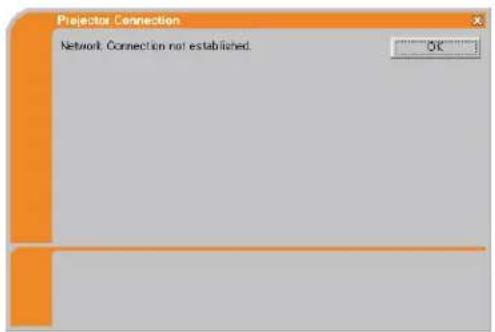
When the connection to the projector could not be established, an error message, "Network Connection not established", will come up.
Click [OK] then the "Live Viewer 3" main menu is displayed even though the network is not established. Click 📄 on the main menu to go back to the item 3.3.3 Connecting to the network. (31)
NOTE • If you selected the My Connection, the “Live Viewer 3” is closed. Check the network setting in the projector, and retry the connection from the item 3.3 Quick connection to the network. (26)
[trouble shooting]
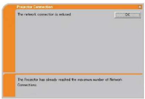
■ The network connection is refused.
The Projector has already reached the maximum number of Network Connections.
The projector can connect up to 5 PCs at the same time.
Click [OK], then the "Live Viewer 3" main menu is displayed even though the network is not established.
After disconnecting a PC, please retry to connect to the network.
3.6 Confirm the connection to your destination (continued)
3.6.3 Setting the Live Mode
This section is intended to explain how to switch to the Live Mode in the MIU on the projector, by using the remote control or a web browser software.
From Web Remote Control on a web browser
1) Click [LIVE MODE] button.
(Refer to the item 4.1.11 Remote Control (86))
From the OSD menu, by using the remote control or keypad on the projector.
1) Turn on the projector, and make sure that the projector image is on screen.
2) Press theMENU button on the remote control or the ▲/▼/◄/► buttons on the projector to show the menu on screen.
3) Use the ▲/▼ cursor buttons to select the Advanced Menu, and use the ▶ cursor button or ENTER button to enter the item.
4) Use the ▲/▼ cursor buttons to select the MIU, and use the ▶ cursor button or ENTER button.
5) Use the ▲/▼ cursor buttons to select the LIVE MODE, and push the ▶ cursor button or ENTER button.
(Refer to 📄 MIU menu in the Operator's Guide
From MY BUTTON function
1) Turn on the projector, and make sure that the projector image is on screen.
2) Press theMENU button on the remote control or the ▲/▼/◄/► buttons on the projector to show the menu on screen.
3) Use the ▲/▼ cursor buttons to select the Advanced Menu, and use the ▶ cursor button or ENTER button to enter the item.
4) Use the ▲/▼ cursor buttons to select the OPTION, and use the ▶ cursor button or ENTER button.
5) Use the ▲/▼ cursor buttons to select the MY BUTTON item, and use the ▶ cursor button or ENTER button to enter the item.
6) Choose 1 or 2 on the MY BUTTON item using the ◀/▶ cursor buttons. Then using the ▲/▼ buttons sets LIVE MODE function to the button.
(Refer to 📄 OPTION menu in the Operator's Guide
3.7 Start the "Live Viewer 3"
When you get the connection between your projector and PC, the "Live Viewer 3" main menu will be shown on the PC screen.
On the main menu you can configure the settings and operate the functions to send your images to the projector in the Live Mode.
3.7.1 Main menu and Operating buttons
1) Menu Type
There are 2 type of the main menu, Easy type and Advanced type, which can be switched on screen.
- When the "Live Viewer 3" is started, the last used type will be screen.
- When the network connection is not established, the Advanced type will be on screen.
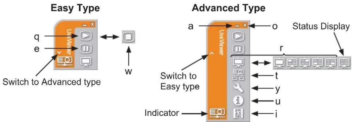
Fig. 3.7.1 a Live Viewer 3 Main menu
2) Operating buttons
q Starting Capture button
The transmission to the projector is started and the images will be displayed in the Live Mode.
The Display mode will be the Single PC mode at first. After that, the last Display mode will be applied.
w Stop button
The image transmission is stopped.
NOTE • The images may not be displayed on screen, if the Start/Stop buttons are clicked repeatedly.
3.7 Start the "Live Viewer 3" (continued)
e Hold button
The image on screen is temporally frozen.
The last image before the button is clicked is remained on screen.
You can revise the image data on your PC without showing it on the projector's screen.
r Display mode button (57)
The button switches the Single PC mode and Multi PC mode.
t Connect button
The screen to select the connection mode is displayed.
Go to the item 3.3.3 (31)
y Option button
The option screen is displayed.
u Information button
The version of the "Live Viewer 3" is displayed.
i, o Close button
The network is disconnected and the "Live Viewer 3" is closed.
a Minimize button
The main menu is closed, and the "Live Viewer 3" icon is displayed on the task tray in your PC. If the icon is double-clicked, the last type of the main menu will be shown on screen.
Connected Disconnected
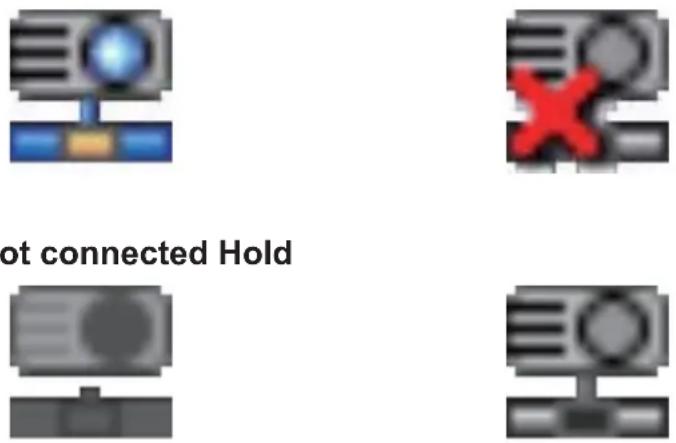
Fig. 3.7.1 b Task tray Icon
3.7 Start the "Live Viewer 3" (continued)
3.7.2 Displaying the status
1) Indicator
The indicator shows the following status.
| Indicator Status Note | ||
 | Not connected | The network connection to the projector is not established yet. |
 | Hold | The network connection is established, but the image transmissions on hold. |
 | Connected | The network connection is established and the images on the PC are being sent to the projector. |
 | Disconnected | The network connection to the projector is disconnected. |
2) Status Display in Multi PC mode
The icon is displayed at the right end of the Display mode buttons.
One of the following icons to inform which quarter screens are used will be shown.
| Status Status icon | |
| No PC is on screen |  |
| One PC is on screen. |  |
| Two PCs are on screen. |  |
| Three PCs are on screen. |  |
| Four PCs are on screen. |  |
NOTE • The status display is refreshed in every 3 seconds.
- If the status cannot be gotten from the projector, it will not be displayed.
3.7 Start the "Live Viewer 3" (continued)
3.7.3 Switching the display mode
The “Live Viewer 3” has the Single PC mode and Multi PC mode. The modes can be switched on the main menu.
1) Click the button on the main menu.
The buttons below are displayed.
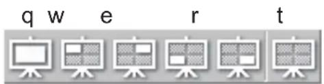
2) Select from q to t buttons, and click it.
q Switching to the Single PC mode : Your image is displayed on full screen.
w-t Switching to the Multi PC mode : Your image is displayed on a quarter screen identified in the button.
3) The projector screen is switched to the mode selected above, and the transmission of your PC image will be started to display your image on the screen.
4) The icon 📋 on the main menu is replaced by the icon you selected.
NOTE • The image transmission will be stopped, when you click the Single mode button while the projector is in the Single PC mode or you click one of the Multi mode buttons that shows the quarter screen which is currently displaying your PC images in the Multi PC mode.
- If the Multi PC mode is selected, the projector screen is automatically divided to 4 zones.
- If the Presenter mode is set on in the PC whose image is currently on screen in the Single PC mode, the 📋 button cannot be clicked on other PCs.
- If the quarter screen that displays images sent from another PC is selected, the network to the PC is disconnected.
(Refer to 📄 MIU menu in the Operator's Guide for the function on the projector.)
3.7 Start the "Live Viewer 3" (continued)
3.7.4 Option menu
Clicking the Option button displays the option menu on screen.
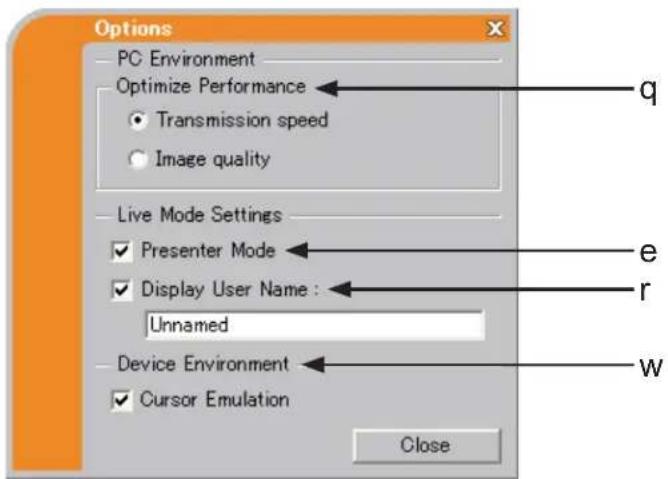
q Optimize Performance
The “Live Viewer 3” captures PC screen in JPEG data and sends the JPEG data to the projector. The “Live Viewer 3” has two options that have different compression rate of JPEG data.
Transmission speed
Speed takes priority over Image quality.
It makes JPEG compression rate higher.
The screen on the projector is rewritten quicker because the transferred data is smaller, but the image quality is worse.
Image quality
Image quality takes priority over Speed.
It makes JPEG compression rate lower.
The screen on the projector is rewritten slower because the transferred data is larger, but the image quality is better.
w Cursor Emulation
If a mouse cursor (pointer) on your PC screen is not displayed on the projector screen, check in the box. The "Live Viewer3" helps you to find the cursor on the screen. If the cursor is on the projector screen, not check it.
3.7 Start the "Live Viewer 3" (continued)
e Presenter Mode
In the Single PC mode, the projector can be occupied by one PC and can block an access from any other PC, if the Presenter mode is selected in the "Live Viewer 3".
While making your presentation, you don't need to worry that the image on screen is unexpectedly switched to an image sent by another PC.
If you want to turn it on, put a check mark in the check box.
NOTE • If the Multi PC mode is selected, the setting for the Presenter mode is invalid.
- When switching from the Multi PC mode to the Single PC mode, the Presenter mode setting of the PC is valid.
- The Presenter Mode is set valid in factory default setting.
r Display User Name
A "User Name" that is up to 20 letters can be input by using alphanumeric characters.
The user name can be displayed on the projector screen, so you can find out whose image is currently on the screen.
(Refer to 📄 MIU menu in the Operator's Guide)
If the check box is not marked, the information is not sent to the projector.
3.8 Profile data
3.8.1 Outline of Profile data
The network setting to connect the projector and PC can be stored as a profile data. Once the data is stored, all you need to do is to select the data to connect to the network. It is recommended when the same network connection is often used.
3.8.2 Making Profile data
The profile data is made on the Manual Configuration screen. (41)
Up to 10 profile data can be stored for each network adapter.
1) Select [Profile] and click [New].
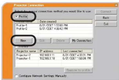
2) The "Create new profile" will come up. If you have already made 10 profile data, you cannot make a new one, until you delete a stored data.
Input all information required for your network connection.
If you want to clear the information you input, click [Clear].
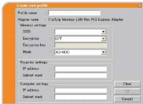
3) Click [OK], after all information is set. If you don't want to store it, click [Cancel].
4) The new profile data is shown in the profile list, if you click [OK].
NOTE • When you make a new profile data, it is strongly recommended to check that the new dada can work properly by selecting the data at the Profile connection. (41)
- If you change a wireless network adapter on the projector or PC, make a new profile data for the adapter.
3.8 Profile data (continued)
3.8.3 Editing Profile data
If necessary, the profile data can be edited on the Manual Configuration screen. (41)
1) Select [Profile], and select one of the data listed in the window.
2) Click [Edit].
3) The "Edit profile" screen will come up.
4) Edit the information required to be revised. If you want to clear all information in the window, click [Clear].
5) Click [OK], after the editing is completed. If you don't want to store it, click [Cancel].
6) The edited profile data is stored and shown in the profile list with the new date created information, if you click [OK].
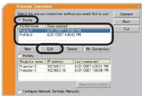
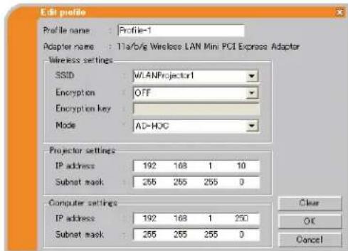
NOTE • When you edit a profile data, it is strongly recommended to check that the edited data can work properly by selecting the data at the Profile connection. (41)
3. Using the Live Mode
3.8 Profile data (continued)
3.8.4 Registering My Connection
One of the profile data, which is often used, can be registered as the My Connection profile data. Once the data is registered, all you need to do is to select the My Connection to connect to the network. (29)
1) Click [My Connection].
2) The "Add My Connection" screen will come up. The currently selected profile data for the My Connection is shown with a check mark in the list.
3) Select one of the profile data listed in the window and put a mark in the check box. The data selected before is turned unmarked.
4) Click [OK], then the window is closed. If you don't want to select a new one, click [Cancel].
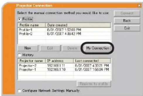
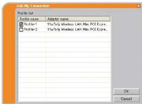
NOTE • If you don't want to use the My Connection, mark no data listed in the window, and click [OK].
- In the list, all profile data are shown no matter which network adapter is selected. You can register a profile data that is not for currently selected network adapter as the My Connection profile data.
3.8 Profile data (continued)
Also, you can register a profile data to My Connection, when the network connection is established. When it is established, the "Connection to Projector successful" screen is displayed. (50)
If you wish to use the current connection setting for My Connection, check in the box for [Register this setting to My Connection].
And then, if it is okay to overwrite the present data for My Connection, click [OK].
A new profile data will be created and it is registered as My Connection profile data.
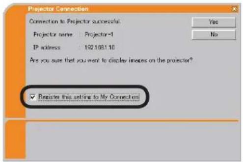
NOTE • If there are already 10 profile data, the check box cannot be checked. Please erase one of the existing profile data.
- The profile name for the stored data is assigned by the "Live Viewer 3" automatically. The name will be shown at the right side of the check box.
4. Management with Web browser software
4. Management with Web browser software
This projector is equipped with the following network functions by using a web browser software.
Confi guring and controlling the projector via a web browser
You can change the settings of or control the projector via a network by using a web browser from a PC that is connected to the same network.
(67)
E-mail Alerts
The projector can automatically send an alert to specified e-mail addresses when the projector requires maintenance or has encountered an error.
(90)
Projector Management using SNMP
This projector is SNMP (Simple Network Management Protocol) compliant, allowing you to monitor it from a remote location using SNMP software. In addition, the projector is able to send failure & warning alerts to a specified PC.
(92)
Event Scheduling
You can schedule the projector to perform various functions according to the date and time.
(93)
MY IMAGE (Still Image Transfer) Display
The projector can display still images that are transferred via the network. (96)
Command Control via the Network
The projector can be controlled using RS-232C commands over a network.
(97)
4.1 Configuring and controlling the projector via a web browser
You can adjust or control the projector via a network from a web browser on a PC that is connected to the same network.
NOTE • Internet Explorer® 5.5 or later is required.
- If JavaScript is disabled in your web browser configuration, you must enable JavaScript in order to use the projector web pages properly. See the Help files for your web browser for details on how to enable JavaScript.
- It is recommended that all web browser updates are installed. It is especially recommended that all users running Internet Explorer® on a Microsoft® Windows® version prior to Windows® XP Service Pack 2 install security update Q832894 (MS04-004) or the web browser interface may not be displayed correctly. And when using an earlier version of Internet Explorer®, during operations the browser will log out after 50 seconds.
4.1 Configuring and controlling the projector via a web browser (Continued)
When configuring or controlling the projector via a web browser, an ID and password are required. There are two types of IDs, Administrator ID and User ID. The following chart describes the differences between Administrator and User IDs.
| Item Description | Administrator User | ||
| Network Information | Displays the projector's current network configuration settings. | √ | √ |
| Network Settings | Displays and configures network settings. | √ N/A | |
| Port Settings | Displays and configures communication port settings. | √ N/A | |
| Mail Settings | Displays and configures e-mail addressing settings. | √ N/A | |
| Alert Settings | Displays and configures failure & warning alerts. | √ N/A | |
| Schedule Settings | Displays and configures schedule settings. | √ N/A | |
| Date/Time Settings | Displays and configures the date and time settings. | √ N/A | |
| Security Settings | Displays and configures passwords and other security settings. | √ N/A | |
| Projector Control Controls the projector. √ √ | |||
| Remote Control Controls the projector like IR remote. √ √ | |||
| Projector Status | Displays and configures the current projector status. | √ | √ |
| Network Restart | Restarts the projector's network connection. | √ N/A | |
4.1 Configuring and controlling the projector via a web browser (Continued)
4.1.1 Logon
Refer to the following for configuring or controlling the projector via a web browser.
Example: If the IP address of the projector is set to 192.168.1.10:
1) Enter "http://192.168.1.10/" into the address bar of the web browser and press "Enter" key or click "→" button. The screen in Fig. 4.1.1a will be displayed.
2) Enter your ID and password and click [Logon].
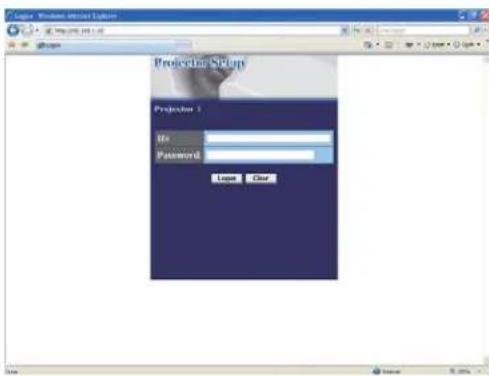
Fig. 4.1.1 a "Logon menu"
Below are the factory default settings for administrator ID, user ID and passwords.
| Item ID Password | |
| Administrator Administrator | |
| User User |
If the logon is successful, either the Fig. 4.1.1 b or Fig. 4.1.1 c screen will be displayed.
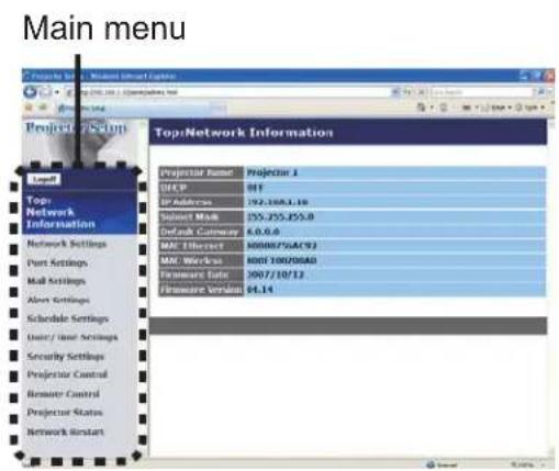
Fig. 4.1.1 b "Logon with Administrator ID"
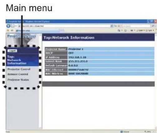
Fig. 4.1.1 c "Logon with User ID"
3) Click the desired operation or configuration item on the main menu located on the left-hand side of the screen.
4.1 Configuring and controlling the projector via a web browser (Continued)
4.1.2 Network Information
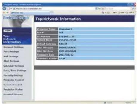
All screen drawings in this manual are shown when you logon with the Administrator ID. Any functions that are available only for the Administrator will not be shown when you logon with the User ID. Refer to the table. (66, 67)
Displays the projector's current network configuration settings.
| Item Description | |
| Projector Name Displays the projector name settings. | |
| DHCP Displays the DHCP configuration settings. | |
| IP Address Displays the current IP address. | |
| Subnet Mask Displays the subnet mask. | |
| Default Gateway Displays the default gateway. | |
| MAC Ethernet Displays the ethernet MAC address. | |
| MAC Wireless | Displays the wireless LAN MAC address.NOTE·MAC wireless will not be displayed when the NETWORK MODE is set to the WIRED even if the wireless network card is mounted. (MIU menu in the Operator's Guide |
| Firmware Date | Displays the network firmware time stamp. This information is only displayed when logged on using an Administrator ID. |
| Firmware Version | Displays the network firmware version number. This information is only displayed when logged on using an Administrator ID. |
4.1 Configuring and controlling the projector via a web browser (Continued)
4.1.3 Network Settings
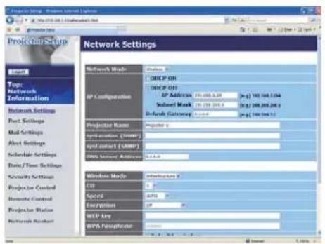
Displays and configures network settings.
| Item Description | ||
| Network Mode Select Network mode “Wired” or “Wireless”. | ||
| IP Configuration Configures network settings. | ||
| DHCP ON Enables DHCP. | ||
| DHCP OFF Disables DHCP. | ||
| IP Address Configures the IP address when DHCP is disabled. | ||
| Subnet Mask Configures the subnet mask when DHCP is disabled. | ||
| Default Gateway Configures the default gateway when DHCP is disabled. | ||
| Projector Name | Configures the name of the projector.The length of the Projector Name can be up to 64 alphanumeric characters. Only alphabets, numbers and following symbols can be used. !"#%&'()*+,-./:;<=>?@[^_^_~ and space | |
| sysLocation (SNMP) | Configures the location to be referred to when using SNMP.The length of the sysLocation can be up to 255 alphanumeric characters. Only numbers ‘0-9’ and alphabet ‘a-z’, ‘A-Z’ can be used. | |
| sysContact (SNMP) | Configures the contact information to be referred to when using SNMP.The length of the sysContact can be up to 255 alphanumeric characters. Only numbers ‘0-9’ and alphabet ‘a-z’, ‘A-Z’ can be used. | |
| DNS Server Address Configures the DNS server address. | ||
| Item Description | ||
| Wireless Mode Select “AD-HOC” or “Infrastructure”. | ||
| CH(Communication channel) | Select using channel between “1” and “11”.NOTE · Depending on the country where you are the channels may vary. In addition, depending on the country or region where you are may be required to use a wireless network card that confirm to the standards in the respective country or region. | |
| Speed(Communication speed) | Select communication speed. | |
| Encryption Select data encryption method. | ||
| WEP Key | Input WEP key, which has same length defined by WEP.When “64bit” or “128bit” is selected, input 10 characters or 26 characters respectively. Only numbers from “0” to “9” and alphabets from “a” to “f” (whichever small or capital characters) can be used.Enter the series of two characters pair. It will be cleared by 0, if the total length is odd. | |
| WPA Passphrase | Input WPA Passphrase. Available number of input characters is 8 to 63. Only alphabets, numbers and following symbols can be used!“#%&’()*+,-./;<=>?@[\]^_‘{}~ and space | |
| SSID | Select an SSID from the list. If you require to set your unique SSID, select [Custom], then set your own SSID following the rules below.Maximum number of input characters is 32.Only alphabets, numbers and following symbols can be used!“#$%&’()*+,-./;<=>?@[\]^_‘{}~ and space. | |
Click [Apply] button to save the settings.
NOTE • The new configuration settings are activated after restarting the network connection. When the configuration settings are changed, you must restart the network connection. You can restart the network connection by clicking [Network Restart] on the main menu.
- If you connect the projector to an existing network, consult a network administrator before setting server addresses.
- The WEP Key, WPA passphrase and SSID settings will not be set if the invalid characters are used.
4.1 Configuring and controlling the projector via a web browser (Continued)
4.1.4 Port Settings
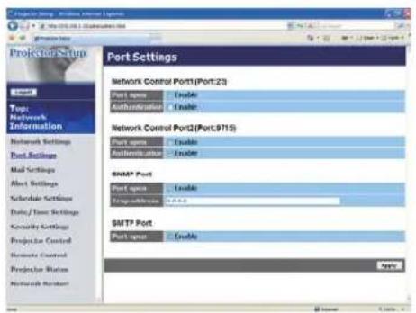
Displays and configures communication port settings.
| Item Description | |
| Network Control Port1 (Port:23) | Configures command control port 1 (Port:23). |
| Port open | Click [Enable] check box to use port 23. |
| Authentication | Click [Enable] check box when authentication is required for this port. |
| Network Control Port2 (Port:9715) | Configures command control port 2 (Port:9715). |
| Port open | Click [Enable] check box to use port 9715. |
| Authentication | Click [Enable] check box when authentication is required for this port. |
| SNMP Port Configures the SNMP port. | |
| Port open Click [Enable] check box to use SNMP. | |
| Trap address | Configures the destination of the SNMP Trap in IP format.• The address allows not only IP address but also domain name if the valid DNS server is setup in the Network Settings. The maximum length of host or domain name is up to 255 characters. |
| SMTP Port Configures the SMTP port. | |
| Port open | Click [Enable] check box to use the e-mail function. |
Click [Apply] button to save the settings.
4.1 Configuring and controlling the projector via a web browser (Continued)
4.1.5 Mail Settings
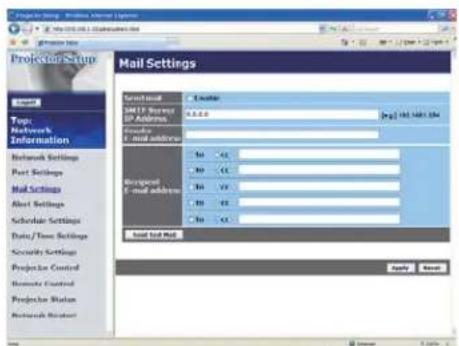
Displays and configures e-mail addressing settings.
| Item Description | |
| Send mail | Click [Enable] check box to use the e-mail function.Configure the conditions for sending e-mail under the Alert Settings. |
| SMTP Server IP Address | Configures the address of the mail server in IP format.• The address allows not only IP address but also domain name if the valid DNS server is setup in the Network Settings. The maximum length of host or domain name is up to 255 characters. |
| Sender E-mail address | Configures the sender e-mail address.The length of the sender e-mail address can be up to 255 alphanumeric characters. |
| Recipient E-mail address | Configures the e-mail address of up to five recipients. You can also specify [TO] or [CC] for each address. The length of the recipient e-mail address can be up to 255 alphanumeric characters. |
Click [Apply] button to save the settings.
NOTE • You can confirm whether the mail settings work correctly using [Send Test Mail] button. Please enable Send mail setting before clicking [Send Test Mail].
- If you connect the projector to an existing network, consult a network administrator before setting server addresses.
4.1 Configuring and controlling the projector via a web browser (Continued)
4.1.6 Alert Settings
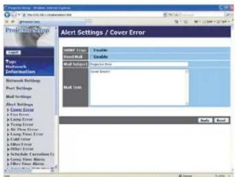
Displays and configures failure & alert settings.
| Alert Item Description | |
| Cover Error The lamp cover | has not been properly fixed. |
| Fan Error The cooling fan is | not operating. |
| Lamp Error | The lamp does not light, and there is a possibility that interior portion has become heated. |
| Temp Error | There is a possibility that the interior portion has become heated. |
| Air Flow Error The internal | temperature is rising. |
| Lamp Time Error Lamp time | over. |
| Cold Error | There is a possibility that the interior portion has become overcooled. |
| Filter Error Filter time over. | |
| Other Error | Other error.If displaying this error, please contact your dealer. |
| Schedule Execution Error | Schedule Execution error. (75) |
| Lamp Time Alarm Lamp time | over Alarm Time setting. |
| Filter Time Alarm Filter time | over Alarm Time setting. |
| Transition Detector Alarm | Transition Detector Alarm. OPTION menu in the Operator's Guide |
| Cold Start | The power switch is turned on.(Off → standby mode) |
| Authentication Failure | The SNMP access is detected from the invalid SNMP community. |
Refer to "Troubleshooting" in the Operator's Guide for further detailed explanation of Error except Other Error and Schedule Execution Error.
4.1 Configuring and controlling the projector via a web browser (Continued)
The Alert Items are shown below.
| Setting Item Description | |
| Alarm Time | Configures the time to alert.(Only Lamp Time Alarm and Filter Time Alarm.) |
| SNMP Trap | Click [Enable] check box to enable SNMP Trap alerts. |
| Send Mail | Click [Enable] check box to enable e-mail alerts.(Except Cold Start and Authentication Failure.) |
| Mail Subject | Configures the subject line of the e-mail to be sent.The length of the subject line can be up to 100 alphanumeric characters.(Except Cold Start and Authentication Failure.) |
| Mail Text | Configures the text of the e-mail to be sent.The length of the text can be up to 1024 alphanumeric characters.(Except Cold Start and Authentication Failure.) |
Click [Apply] button to save the settings.
NOTE • The trigger of Filter Error e-mail is depending on the FILTER MESSAGE setting in the SERVICE item of the OPTION menu which defines the period until the filter message is displayed on the projector screen. The e-mail will be sent when the filter timer exceeds 500, 1000, 1500 or 2000 hours based on the configuration. No notification e-mail will be sent if the FILTER MESSAGE is set to TURN OFF. (OPTION menu in the Operator's Guide)
- Lamp Time Alarm is defined as a threshold for e-mail notification (reminder) of the lamp timer. When the lamp hour exceeds this threshold that is configured through the Web page, the e-mail will be sent out.
- Filter Time Alarm is defined as a threshold for e-mail notification (reminder) of the filter timer. When the filter hour exceeds this threshold, the e-mail will be sent out.
4.1 Configuring and controlling the projector via a web browser (Continued)
4.1.7 Schedule Settings
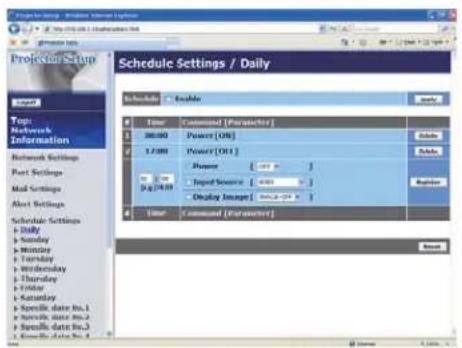
Displays and configures schedule settings.
| Item Description | |
| Daily Configures the daily schedule. | |
| Sunday Configures the Sunday schedule. | |
| Monday Configures the Monday schedule. | |
| Tuesday Configures the Tuesday schedule. | |
| Wednesday Configures the Wednesday schedule. | |
| Thursday Configures the Thursday schedule. | |
| Friday Configures the Friday schedule. | |
| Saturday Configures the Saturday schedule. | |
| Specific date No.1 Configures the specific date (No.1) schedule. | |
| Specific date No.2 Configures the specific date (No.2) schedule. | |
| Specific date No.3 Configures the specific date (No.3) schedule. | |
| Specific date No.4 Configures the specific date (No.4) schedule. | |
| Specific date No.5 Configures the specific date (No.5) schedule. |
4.1 Configuring and controlling the projector via a web browser (Continued)
The schedule settings are shown below.
| Item Description | |
| Schedule | Click [Enable] check box to enable the schedule. |
| Date (Month/Day) | Configures the month and date.This item appears only when Specific date (No. 1-5) is selected. |
Click [Apply] button to save the settings.
The current event settings are displayed on the schedule list. To add additional functions and events, set the following items.
| Item Description | |
| Time Configures the time to execute commands. | |
| Command[Parameter] | Configures the commands to be executed. |
| Power Configures the parameters for power control. | |
| Input Source Configures the parameters for input switching. | |
| Display Image | Configures the parameters for display of transferred image data (96). |
Click [Register] button to add new commands to the schedule list.
Click [Delete] button to delete commands from the schedule list.
Click [Reset] button to delete all commands and reset the schedule settings from the schedule list.
NOTE • After the projector is moved, check the date and time set for the projector before configuring the schedules. Strong shock may make the date and time settings (77) get out of tune.
4.1 Configuring and controlling the projector via a web browser (Continued)
4.1.8 Date/Time Settings
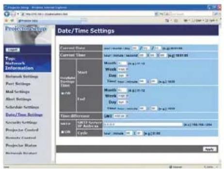
Displays and configures the date and time settings.
| Item Description | |||
| Current Date | Configures the current date in year/month/day format. | ||
| Current Time | Configures the current time in hour:minute:second format. | ||
| Daylight Savings Time | Click [ON] check box to enable daylight savings time and set the following items. | ||
| Start Configures the date and time daylight savings time begins. | |||
4.1 Configuring and controlling the projector via a web browser (Continued)
| Item Description | ||
| Time difference | Configures the time difference. Set the same time difference as the one set on your PC. If unsure, consult your IT manager. | |
| SNTP | Click the [ON] check box to retrieve Date and Time information from the SNTP server and set the following items. | |
| SNTP Server IP Address | ||
| Cycle | ||
Click [Apply] button to save the settings.
NOTE • If you connect the projector to an existing network, consult a network administrator before setting server addresses.
- To enable the SNTP function, the time difference must be set.
- The projector will retrieve Date and Time information from the time server and override time settings when SNTP is enabled.
- The internal clock's time may not remain accurate. Using SNTP is recommended to maintain accurate time.
4.1 Configuring and controlling the projector via a web browser (Continued)
4.1.9 Security Settings
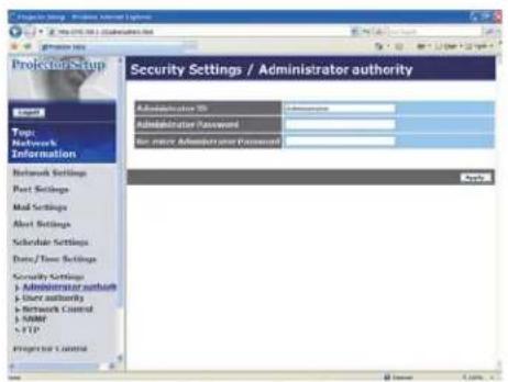
Displays and configures passwords and other security settings.
| Item Description | |
| Administrator authority Configures the Administrator ID and password. | |
| Administrator ID | Configures the Administrator ID.The length of the text can be up to 32 alphanumeric characters. |
| Administrator Password | Configures the Administrator password.The length of the text can be up to 255 alphanumeric characters. |
| Re-enter Administrator Password | Reenter the above password for verification. |
| User authority Configures the User ID and password. | |
| User ID | Configures the User ID.The length of the text can be up to 32 alphanumeric characters. |
| User Password | Configures the User password.The length of the text can be up to 255 alphanumeric characters. |
| Re-enter User Password | Reenter the above password for verification. |
4.1 Configuring and controlling the projector via a web browser (Continued)
| Item Description | |
| Network Control | Configures the Authentication password for the command control. |
| Authentication Password | Configures the Authentication password. The length of the text can be up to 32 alphanumeric characters. |
| Re-enter Authentication Password | Reenter the above password for verification. |
| SNMP Configures the community name if SNMP is used. | |
| Community name | Configures the community name. The length of the text can be up to 64 alphanumeric characters. |
| FTP Configures the FTP user and password. | |
| User | Configures the user name. The length of the text can be up to 32 alphanumeric characters. |
| Password | Configures the password. The length of the text can be up to 32 alphanumeric characters. |
| Re-enter Password Re | enter the above password for verification. |
Click [Apply] button to save the settings.
- Only numbers '0-9' and alphabet 'a-z', 'A-Z' can be used. NOTE
4.1 Configuring and controlling the projector via a web browser (Continued)
4.1.10 Projector Control
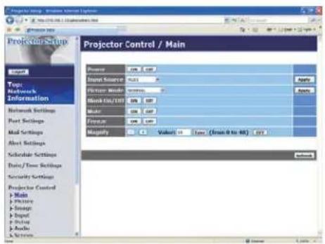
The items shown in the table below can be performed using the Projector Control menu.
Select an item using the up and down arrow keys on the PC.
Most of the items have a submenu. Refer to the table below for details.
NOTE • The setting value may not match with the actual value if the user changes the value manually. In that case, please refresh the page by clicking [Refresh] button.
Controls the projector.
| Item Description | ||
| Main | ||
| Power Turns the power on/off. | ||
| Input Source Selects the input source. | ||
| Picture Mode Selects the picture mode setting. | ||
| Blank On/Off Turns Blank on/off. | ||
| Mute Turns Mute on/off. | ||
| Freeze Turns Freeze on/off. | ||
| Magnify Controls the magnify setting.In some input signal sources, it might stop “Magnify” even though it does not reach to maximum setting value. | ||
| Picture | ||
| Brightness Adjusts the brightness setting. | ||
| Contrast Adjusts the contrast setting. | ||
| Gamma Selects the gamma setting. | ||
| Color Temp Selects the color temperature setting. | ||
| Color Adjusts the color setting. | ||
| Tint Adjusts the tint setting. | ||
| Sharpness Adjusts the sharpness setting. | ||
| Active Iris Selects the active iris setting. | ||
| MyMemory Save Saves the MyMemory data. | ||
| MyMemory Recall Recalls the MyMemory data. | ||
| Image | ||
| Aspect Selects the aspect setting. | ||
| Over Scan Adjusts the over scan setting. | ||
| V Position Adjusts the vertical position. | ||
| H Position Adjusts the horizontal position. | ||
| H Phase Adjusts the horizontal phase. | ||
| H Size Adjusts the horizontal size. | ||
| Auto Adjust Execute Performs the automatic adjustment. | ||
| Input | ||
| Progressive Selects the progressive setting. | ||
| Video NR Selects the video noise reduction setting. | ||
| 3D-YCS Selects the 3D-YCS setting. | ||
| Color Space Selects the color space. | ||
| Component Selects the COMPONENT port setting. | ||
| C-Video Format Selects the video format setting. | ||
| S-Video Format Selects the s-video format setting. | ||
| HDMI | Selects the HDMI setting. | |
| Frame Lock-RGB1 | Turns the frame lock-RGB1 function on/off. | |
| Frame Lock-RGB2 | Turns the frame lock-RGB2 function on/off. | |
| Frame Lock-HDMI | Turns the frame lock-HDMI function on/off. | |
| RGB in-1 | Selects the RGB1 input signal type. | |
| RGB in-2 | Selects the RGB2 input signal type. | |
| Setup | ||
| Auto Keystone Execute | Performs the automatic keystone distortion setting. | |
| Keystone V | Adjusts the vertical keystone distortion setting. | |
| Keystone H | Adjusts the horizontal keystone distortion setting. | |
| Whisper Selects the whisper mode. | ||
| Mirror | Selects the mirror status. | |
| Monitor Out-RGB1 | Assigns the RGB OUT when the RGB1 input port is selected. | |
| Monitor Out-RGB2 | Assigns the RGB OUT when the RGB2 input port is selected. | |
| Monitor Out-HDMI | Assigns the RGB OUT when the HDMI input port is selected. | |
| Monitor Out-MIU | Assigns the RGB OUT when the MIU input port is selected. | |
| Monitor Out-Component | Assigns the RGB OUT when the COMPONENT input port is selected. | |
| Monitor Out-S-Video | Assigns the RGB OUT when the S-VIDEO input port is selected. | |
| Monitor Out-Video | Assigns the RGB OUT when the VIDEO input port is selected. | |
| Monitor Out-Standby | Assigns the RGB OUT in the standby mode. | |
| Audio | ||
| Volume Adjusts the volume setting. | ||
| Treble Adjust the Treble setting. | ||
| Bass Adjusts the Bass setting. | ||
| SRS WOW Selects the SRS WOW setting. | ||
| Speaker Turns the built-in speaker on/off. | ||
| Audio-RGB1 Assigns the AUDIO- RGB1 input port. | ||
| Audio-RGB2 Assigns the AUDIO- RGB2 input port. | ||
| Audio-HDMI Assigns the AUDIO- HDMI input port. | ||
| Audio-MIU Assigns the AUDIO- MIU input port. | ||
| Audio-Component Assigns the AUDIO- COMPONENT input port. | ||
| Audio-S-Video Assigns the AUDIO- S-VIDEO input port. | ||
| Audio-Video Assigns the AUDIO- VIDEO input port. | ||
| Audio Out Standby Assigns the AUDIO OUT in the standby mode. | ||
| HDMI Audio Selects the HDMI audio setting. | ||
| Screen | ||
| Language Selects the language for the OSD. | ||
| Menu Position V Adjusts the vertical Menu position. | ||
| Menu Position H Adjusts the horizontal Menu position. | ||
| Blank Selects the Blank mode. | ||
| Startup Selects the startup screen mode. | ||
| MyScreen Lock Turns MyScreen lock function on/off. | ||
| Message Turns the message function on/off. | ||
| Template Selects the template setting. | ||
4.1 Configuring and controlling the projector via a web browser (Continued)
| Item Description | |
| Option | |
| Auto Search Turns the automatic signal search function on/off. | |
| Auto Keystone | Turns the automatic keystone distortion correction function on/off. |
| Auto on Turns the auto on function on/off. | |
| Auto off | Configures the timer to shut off the projector when no signal is detected. |
| My Button-1 | Assigns the functions for the MY BUTTON1 button on the included remote control. |
| My Button-2 | Assigns the functions for the MY BUTTON2 button on the included remote control. |
| My Source Selects the My Source setting. | |
| Remote Receiv. Front Enable/Disable remote receiv. front. | |
| Remote Receiv. Rear Enable/Disable remote receiv. rear. | |
| Remote Receiv. Top Enable/Disable remote receiv. top. | |
| Remote Freq. Normal Enables/Disables the remote control signal frequency normal. | |
| Remote Freq. High Enables/Disables the remote control signal frequency high. | |
| Closed Caption | |
| Display Selects Closed Caption DISPLAY setting. | |
| Mode Selects Closed Caption MODE setting. | |
| Channel Selects Closed Caption CHANNEL setting. | |
4.1 Configuring and controlling the projector via a web browser (Continued)
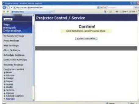
The Service item in the Projector Control menu is shown only when you logon with the Administrator ID.
The items shown in the table below can be performed using the Projector Control menu. Click [Quit Presenter Mode].
| Item Description | |
| Service | |
| Quit Presenter Mode | Quit compulsorily from the Presenter mode. |
4.1 Configuring and controlling the projector via a web browser (Continued)
4.1.11 Remote Control
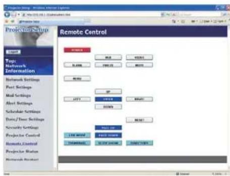
You can use your Web browser to control the projector.
- Do not attempt to control the projector with the projector's remote control and via your Web browser at the same time. It may cause some operational errors in the projector.
The functions on the bundled remote control are assigned to the Web Remote Control screen.
| Item Description | ||
| POWER Assigned the same operation as | STANDBY/ON button. | |
| RGB Assigned the same operation as | RGB button. | |
| VIDEO Assigned the same operation as | VIDEO button. | |
| BLANK Assigned the same operation as | BLANK button. | |
| FREEZE Assigned the same operation as | FREEZE button. | |
| MUTE Assigned the same operation as | MUTE button. | |
| MENU Assigned the same operation as | MENU button. | |
| UP Assigned the same operation as ▲ button. | ||
| DOWN Assigned the same operation as ▼ button. | ||
| LEFT Assigned the same operation as ◀ button. | ||
| RIGHT Assigned the same operation as ▶ button. | ||
| ENTER Assigned the same operation as | ENTER button. | |
| RESET | Assigned the same operation as RESET button. | |
| PAGE UP | Assigned the same operation as PAGE UP button. | |
| PAGE DOWN | Assigned the same operation as PAGE DOWN button. | |
4.1 Configuring and controlling the projector via a web browser (Continued)
The functions on PC-LESS PRESENTATION menu are assigned to the Web Remote Control screen.
| Item Description | |
| LIVE MODE Selecting this | item sets the projector onto the “Live Mode”. |
| THUMBNAIL | Selecting this item sets the projector onto the “Thumbnail mode”. |
| SLIDE SHOW | Selecting this item sets the projector onto the “Slide Show mode”. |
| DIRECTORY | Selecting this item sets the projector onto the “Directory mode”. |
NOTE • The Web Remote Control does not support repeat function that performs an action while holding a button clicked down.
- Since the repeat function is not available, click the button repeatedly as many times as you require.
- Even if you hold the button clicked down for a while, the Web Remote Control sends your request command one time only. Release the button, then click it again.
- When [POWER] button is pushed, a message window comes up to confirm the operation. If you wish to turn it off, push [OK], otherwise push [Cancel].
- [PAGE DOWN] and [PAGE UP] buttons on the Web Remote Control cannot be used as mouse emulation function of the projector.
4.1 Configuring and controlling the projector via a web browser (Continued)
4.1.12 Projector Status
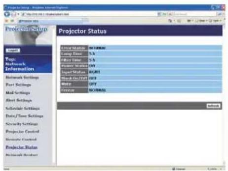
Displays and configures the current projector status.
| Item Description | |
| Error Status Displays the current error status | |
| Lamp Time Displays the usage time for the current lamp. | |
| Filter Time Displays the usage time for the current filter. | |
| Power Status Displays the current power status. | |
| Input Status Displays the current input signal source. | |
| Blank On/Off Displays the current Blank on/off status. | |
| Mute Displays the current Mute on/off status. | |
| Freeze Displays the current Freeze status. | |
4.1 Configuring and controlling the projector via a web browser (Continued)
4.1.13 Network Restart
Restarts the projector's network connection.
Item Description
Restart
Restarts the projector's network connection in order to activate new configuration settings.
NOTE • Restarting requires you to re-log on in order to further control or configure the projector via a web browser. Wait 10 seconds or more after clicking [Restart] button to log on again.
- The Logon menu (67) is displayed after restarting the projector's network connection if the DHCP is set to ON.
4.1.14 Logoff
When [Logoff] is clicked, the Logon menu is displayed (67).
4.2 E-mail Alerts
The projector can automatically send an alert message to the specified e-mail addresses when the projector detects a certain condition that is requiring maintenance or detected an error.
NOTE • Up to five e-mail addresses can be specified.
- The projector may be not able to send e-mail if the projector suddenly loses power.
Mail Settings (72)
To use the projector's e-mail alert function, please configure the following items through a web browser.
Example: If the IP address of the projector is set to 192.168.1.10:
1) Enter "http://192.168.1.10/" into the address bar of the web browser.
2) Enter the Administrator ID and password and click [Logon].
3) Click [Port Settings] on the main menu.
4) Click [Enable] check box to open the SMTP Port.
5) Click [Apply] button to save the settings.
6) Click [Mail Settings] and configure each item. Refer to the item 4.1.5 Mail Settings (72) for further information.
7) Click [Apply] button to save the settings.
NOTE • Click [Send Test Mail] button in [Mail Settings] to confirm that the e-mail settings are correct. The following mail will be delivered to the specified addresses.
Subject line :Test Mail
Date <Testing date>
Time <Testing time>
IP Address <Projector IP address>
MAC Address <Projector MAC address>
4.2 E-mail Alerts (Continued)
8) Click [Alert Settings] on the main menu to configure the E-mail Alerts settings.
9) Select and configure each alert item. Refer to the item 4.1.6 Alert Setting (73) for further information.
10) Click [Apply] button to save the settings.
Failure/Warning e-mails are formatted as follows:
Subject line :
Text : <Mail text>
Date <Failure/Warning date>
Time <Failure/Warning time>
IP Address <Projector IP address>
MAC Address <Projector MAC address>
4.3 Projector Management using SNMP
The SNMP (Simple Network Management Protocol) enables to manage the projector information, which is a failure or warning status, from the computer on the network. The SNMP management software will be required on the computer to use this function.
NOTE • It is recommended that SNMP functions be carried out by a network administrator.
- SNMP management software must be installed on the computer to monitor the projector via SNMP.
SNMP Settings (71)
Configure the following items via a web browser to use SNMP.
Example: If the IP address of the projector is set to 192.168.1.10:
1) Enter "http://192.168.1.10/" into the address bar of the web browser.
2) Enter the Administrator ID and Password and click [Logon].
3) Click [Port Settings] on the main menu.
4) Click [Enable] check box to open the SNMP Port. Set the IP address to send the SNMP trap to when a Failure/Warning occurs.
5) Click [Security Settings] on the main menu.
6) Click [SNMP] and set the community name on the screen that is displayed.
7) Configure the settings for Trap transmission of Failures/Warnings. Click [Alert Settings] on the main menu and select the Failure/Warning item to be configured.
8) Click [Enable] check box to send out the SNMP trap for Failures/Warnings. Clear [Enable] check box when SNMP trap transmission is not required.
9) Click [Apply] button to save the settings.
4.4 Event Scheduling
The scheduling function enables to setup scheduled events including power on / power off. It enables to be “self-management” projector.
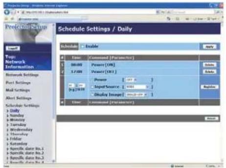
NOTE • You can schedule the following control events: Power ON/OFF, Input Source and Transferred Image Display.
- The power on / off event has the lowest priority among the all events that are defined at the same time.
• There are 3 types of Scheduling, 1) daily 2) weekly 3) specific date. (75)
- The priority for scheduled events is as follows 1) specific date 2) weekly 3) daily.
- Up to five specific dates are available for scheduled events. Priority is given to those with the lower numbers when more than one event has been scheduled for the same date and time (e.g., 'Specific day No. 1' has priority over 'Specific day No. 2' and so on.
- Be sure to set the date and time before enabling scheduled events. (77)
4.4 Event Scheduling (Continued)
Schedule Settings (75)
Schedule settings can be configured from a web browser.
Example: If the IP address of the projector is set to 192.168.1.10:
1) Enter "http://192.168.1.10/" into the address bar of the web browser.
2) Enter the Administrator ID and password and click [Logon].
3) Click [Schedule Settings] on the main menu and select the required schedule item. For example, if you want to perform the command every Sunday, please select [Sunday].
4) Click [Enable] check box to enable scheduling.
5) Enter the date (month/day) for specific date scheduling.
6) Click [Apply] button to save the settings.
7) After configure the time, command and parameters, click [Register] to add the new event.
8) Click [Delete] button when you want to delete a schedule.
There are three types of scheduling.
1) Daily: Perform the specified operation at a specified time every day.
2) Sunday \~ Saturday: Perform the specified operation at the specified time on a specified day of the week.
3) Specific date: Perform the specified operation on the specified date and time.
NOTE • In Standby mode the power indicator will flash green for approx. 3 seconds when at least 1 “Power ON” schedule is saved.
- When the schedule function is used, the power cord must be connected to the projector and the outlet and the power switch must be turned on, [I]. The schedule function does not work when the power switch is turned off, [O] or the breaker in a room is tripped. The power indicator will lights orange or green when the projector gets is receiving the power.
4.4 Event Scheduling (Continued)
Date/Time Settings (77)
The Date/Time setting can be adjusted via a web browser.
Example: If the IP address of the projector is set to 192.168.1.10:
1) Enter "http://192.168.1.10/" into the address bar of the web browser.
2) Enter the Administrator ID and Password and click [Logon].
3) Click [Date/Time Settings] on the main menu and configure each item. Refer to the item 4.1.8 Data/Time Settings for further information.
4) Click [Apply] button to save the settings.
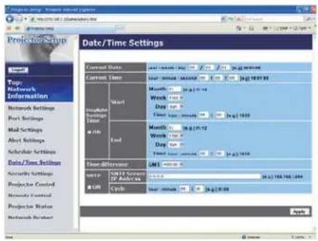
NOTE • The battery for the built in clock may be dead if the clock loses time even when the date and time have been set correctly. Replace the battery by following the instructions on replacing the battery.
Internal clock battery in the Operator's Guide
- The internal clock's time may not remain accurate. Using SNTP is recommended to maintain accurate time.
4.5 MY IMAGE (Still Image Transfer) Display
The projector can display a still image in an SD memory card or USB memory that is transferred via the network. (Fig. 4.5)
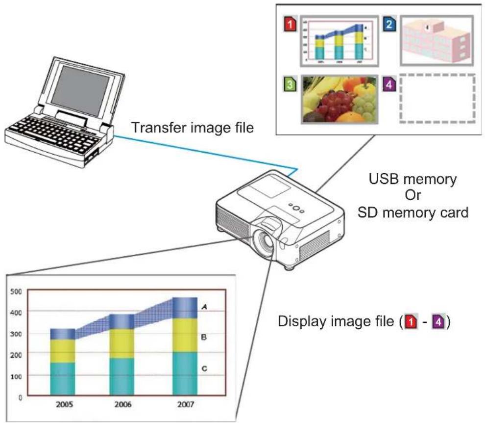
flowchart
graph TD
    A["Laptop"] -->|Transfer image file| B["LED Display"]
    B --> C["Display image file (1 - 4)"]
    subgraph Image File Growth
        D["2005: Core Image File"]
        E["2006: Core Image File"]
        F["2007: Core Image File"]
    end
Fig. 4.5 Still Image Transfer
MY IMAGE transmission requires an exclusive application for your PC. You can download it from the 3M web site (http://www.3m.com/meetings). Refer to the manual for the application for instructions.
To display the transferred image, select the MY IMAGE item in the MIU menu. For more information, please see the description of the MY IMAGE item of the MIU menu. (MIU menu in Operator's Guide
NOTE • Supported file types are JPEG, Bitmap and PNG.
- It is possible to allocate the image file up to 4 in the maximum.
- The image file also can be displayed by using schedule function from the web browser. Refer to the item 4.4 Event Scheduling (93) in detail.
4.6 Command Control via the Network
You can configure and control the projector via the network using RS-232C commands.
Communication Port
The following two ports are assigned for the command control.
TCP #23
TCP #9715
Command Control Settings (71)
Configure the following items from a web browser when command control is used.
Example: If the IP address of the projector is set to 192.168.1.10:
1) Enter "http://192.168.1.10/" into the address bar of the web browser.
2) Enter the Administrator ID and password and click [Logon].
3) Click [Port Settings] on the main menu.
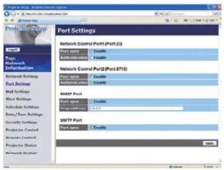
4) Click [Enable] check box to open Network Control Port1 (Port: 23) to use TCP #23. Click [Enable] check box for [Authentication] setting when authentication is required, otherwise clear the check box.
5) Click [Enable] check box to open Network Control Port2 (Port: 9715) to use TCP #9715. Click [Enable] check box for [Authentication] setting when authentication is required, otherwise clear the check box.
6) Click [Apply] button to save the settings.
4. Management with Web browser software
4.6 Command Control via the Network (Continued)
When the authentication setting is enabled, the following settings are required.

7) Click [Security Settings] on the main menu.
8) Click [Network Control] and enter the desired authentication password.
* See NOTE.
9) Click [Apply] button to save the settings.
NOTE • The Authentication Password will be the same for Network Control Port1 (Port: 23), Network Control Port2 (Port: 9715).
4.6 Command Control via the Network (Continued)
Command Format
Command formats differ among the different communication ports.
- TCP #23
You can use the RS-232C commands without any changes. The reply data format is the same as the RS-232C commands. However, the following reply will be sent back in the event of authentication failure when authentication is enabled.
| Reply Error code | ||
| 0x1F 0x04 0x00 | ||
- TCP #9715
Send Data format
The following formatting is added to the header (0x02), Data length (0x0D), Checksum (1byte) and Connection ID (1 byte) of the RS-232C commands.
| Header Data length RS-232Ccommand Check Sum | Connection ID | |||
| 0x02 0x0D 13 bytes 1 byte 1 byte | ||||
Header → 0x02, Fixed
Data length → RS-232C commands byte length (0x0D, Fixed)
RS-232C command → RS-232C commands that start with 0xBE 0xEF (13 bytes)
Check Sum → This is the value to make zero on the addition of the lower 8 bits from the header to the checksum.
Connection ID → Random value from 0 to 255 (This value is attached to the reply data)
4.6 Command Control via the Network (Continued)
Reply Data format
The connection ID (the data is same as the connection ID data on the sending data format) is attached to the RS-232C commands reply data.
| Reply | Connection ID |
| 0x06 1 byte | |
| Reply | Connection ID |
| 0x15 1 byte | |
| Reply Error code | Connection ID |
| 0x1C 2 bytes 1 byte |
| Reply Data | Connection ID |
| 0x1D 2 bytes 1 byte |
| Reply Status code | Connection ID |
| 0x1F 2 bytes 1 byte |
| Reply | Authentication Error code | Connection ID | |
| 0x1F 0x04 | 0x00 1 | byte | |
4.6 Command Control via the Network (Continued)
Automatic Connection Break
The TCP connection will be automatically disconnected after there is no communication for 30 seconds after being established.
Authentication
The projector does not accept commands without authentication success when authentication is enabled. The projector uses a challenge response type authentication with an MD5 (Message Digest 5) algorithm. When the projector is using a LAN, a random 8 bytes will be returned if authentication is enabled. Bind this received 8 bytes and the Authentication Password and digest this data with the MD5 algorithm and add this in front of the commands to send.
Following is a sample if the Authentication Password is set to "password" and the random 8 bytes are "a572f60c".
1) Select the projector.
2) Receive the random 8 bytes "a572f60c" from the projector.
3) Bind the random 8 bytes "a572f60c" and the Authentication Password "password" and it becomes "a572f60cpassword".
4) Digest this bind "a572f60cpassword" with MD5 algorithm. It will be "e3d97429adffa11bce1f7275813d4bde".
5) Add this "e3d97429adffa11bce1f7275813d4bde" in front of the commands and send the data.
Send "e3d97429adffa11bce1f7275813d4bde"+command.
6) When the sending data is correct, the command will be performed and the reply data will be returned. Otherwise, an authentication error will be returned.
NOTE • As for the transmission of the second or subsequent commands, the authentication data can be omitted when the same connection.
5. PC-LESS Presentation
5.1 Outline of the PC-LESS Presentation
The PC-LESS Presentation reads image data from storage media inserted into SD CARD slot or AUX I/O port and displays the image on the following modes. The PC-LESS Presentation can be operated on the OSD menu in the projector screen or via a web browser software in your PC connected to the projector through the network.
The feature allows you to make your presentation without your PC.
- Thumbnail Mode (104)
- Full Screen Mode (108)
- Slide Show Mode (110)
- Directory Tree View (112)
![Thumbnail Mode THUMBIAL [31] ACLESS PRESENTATION MOUNT REFRESH CLOCK SHOW START 41 STOP FREE INTERNAL LOW MOUNT OUT TIME ADD](/content/2026/05/843273/images/62c6adbfa91bf764fbe84774941916ddfe2e2725dc77a71002dc72cdb48244ad.jpg)
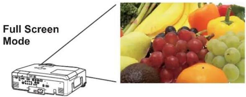
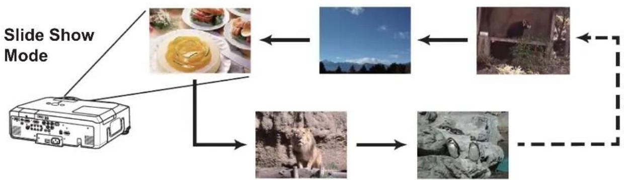
flowchart
graph TD
    A["Monitor with food and dishes"] --> B["Image: landscape photo"]
    B --> C["Image: outdoor scene"]
    C --> D["Image: animals photo"]
    D --> E["Video image"]
    style A fill:#f9f,stroke:#333
    style B fill:#ccf,stroke:#333
    style C fill:#cfc,stroke:#333
    style D fill:#fcc,stroke:#333
    style E fill:#ffc,stroke:#333
5.1 Outline of the PC-LESS Presentation (continued)
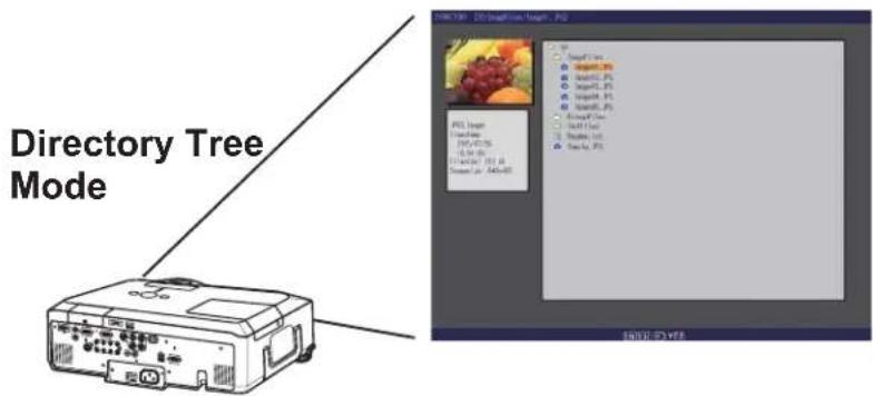
[Supported storage media]
- SD memory card
• USB memory (USB memory type, USB hard disk and USB card reader type)
NOTE • USB memory reader (adapter) that has more than 1 USB slot is not supported (if the adapter is acknowledged as multiple devices connected).
• USB hub is not supported.
• Security USB memory is not supported.
- Some SD memory cards and USB memories may not work correctly.
- SDHC (4GB etc) SD memory card is not supported. Up to 2GB card is supported.
- SD memory and the wireless network card (option) cannot be inserted at the same time.
- Be careful to insert and remove SD memory card and USB memory.
(Using a USB storage/Using an SD card in the Operator's Guide
[Supported format]
• FAT12, FAT16 and FAT32
• NTFS is not supported.NOTE
[Supported file format]
- JPEG (.jpeg, .jpg) * Progressive is not supported.
- Bitmap (.bmp) * 16bit mode and compressed bitmap is not supported.
- PNG (.png) * Interlace PNG is not supported.
- MPEG4 (.mp4) * Supported bit resolution rate is less than 1Mbps in Simple Profile.
Supported resolution is less than VGA.
Supported Audio format is only AAC.
5.2 Thumbnail mode
The Thumbnail mode displays the images stored in an SD or USB storage media in thumbnail screen. Maximum 12 images are displayed in a screen.
If you wish, you can jump into the Full Screen Mode or Slide Show mode, after you select some images in the Thumbnail mode.
![THUMBAIL [SD] 1 2 3 4 5 6 7 8 9 10 11 12 PC-LESS PRESENTATION MENU REFRESH SLIDE SHOW START #1 STOP #999 INTERVAL 10c MODE ONE TIME PLAY Selected image Thumbnail menu Thumbnail images ENTER, YES](/content/2026/05/843273/images/d09cebf893e48a5ab7be9ad0250b363ec2bfe120f7ca6203bae0163b0efaa0db.jpg)
Fig. 5.2 Thumbnail Mode
5.2.1 Starting the Thumbnail mode
The Thumbnail mode can be started from the OSD menu in the projector or from a web browser software on your PC.
from the OSD menu
1) Save JEPG or other supported files (103) into root directory in a SD or USB storage media.
2) Insert the SD memory card into the SD card slot on the projector or the USB memory into the AUX I/O port on the projector. (Using a USB storage/Using an SD card in the Operator's Guide
3) Press theMENU button on the remote control or the ▲/▼/◄/► buttons on the projector to show the menu on screen.
4) Use the ▲/▼ cursor buttons to select the Advanced Menu, and use the ▶ cursor button to enter the item.
5) Use the ▲/▼ cursor buttons to select the MIU, and use the ▶ cursor button to enter the item.
5.2 Thumbnail mode (continued)
6) Use the ▲/▼ cursor buttons to select the PC-LESS PRESENTATION, and push the ▶ cursor button.
![MENU [RGB 1] PICTURE IMAGE INPUT SETUP AUDIO SCREEN OPTION MIU C.C. EASY MENU LIVE MODE LIVE MODE SETTING PC-LESS PRESENTATION SETUP PROJECTOR NAME MY IMAGE INFORMATION SERVICE](/content/2026/05/843273/images/86df569a1335aeaa7dd3d9d76047da5accc9686d0cebf77f0248ccb2b0e9a066.jpg)
7) Use the ▲/▼ cursor buttons to select the THUMBNAIL, and push the ▶ cursor button to perform it. The picture in Fig. 5.2 will be on screen.
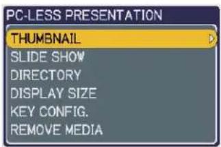
from a web browser software
1) Save JEPG or other supported files (103) into root directory in a SD or USB storage media.
2) Insert the SD memory card into the SD card slot on the projector or the USB memory into the AUX I/O port on the projector. (Using a USB storage/Using an SD card in the Operator's Guide
3) Connect the projector and your PC through the network. 11 or 16 or 26)
4) Start a web browser software and logon to the projector. 67)
5) Select the Remote Control in the main menu to have the Remote Control screen on your PC.
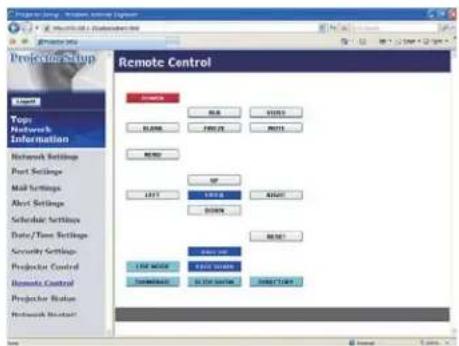
6) Select the THUMBNAIL and click it. The picture in Fig. 5.2 will be on screen.
5.2 Thumbnail mode (continued)
5.2.2 Operating by buttons or keys
You can control the images in the thumbnail screen with the remote control or keypad or a web browser software. The following functions can be supported while the thumbnail is displayed.
| Button operation | Functions | ||
| The remote control | The keypad on the projector | Web Remote in web browser software. | |
| ▲/▼/◄/► ▲/▼/◄/► UP/DOWN/LEFT/RIGHT Move cursor | |||
| PAGE UPPAGE DOWN | - | PAGE UPPAGE DOWN | Switches pages |
| ENTER INPUT ENTER | Displays selected image on full screen | ||
| MENU - MENU | Displays PC-LESS PRESENTATION menu | ||
* These operations are not accessible while the projector OSD menu is displayed.
NOTE • The Thumbnail mode shows 12 pictures in 1 page as maximum.
- It is not possible to change the input port by INPUT button when THUMBNAIL, SLIDE SHOW, or DIRECTORY is displayed.
- Display the projector OSD menu before changing the input port.
- Some error Icons will be displayed in thumbnail.

This file seems to be broken or not supported format.

The file name exists in the playlist file (116), but the actual file does not exist anywhere.
5.2 Thumbnail mode (continued)
5.2.3 Operation on the Thumbnail menu
At the right side of the Thumbnail screen, you can find the Thumbnail menu.
1) PC-LESS PRESENTATION MENU:
Move the cursor to the PC-LESS PRESENTATION menu, and push the ▶ cursor button on the remote control or projector, or [RIGHT] on the Web Remote Control. The PC-LESS PRESENTATION menu will be displayed.
2) REFLESH:
Move the cursor to the REFLESH, and push the ▶ cursor button on the remote control or projector, or [RIGHT] on the Web Remote Control. Then, the warning message for the REFRESH will be displayed. The Refresh is a function to initialize the playlist. (116) If you initialize it, the thumbnail screen is renewed and the images are back to the original condition.
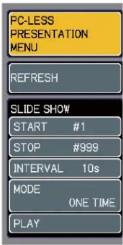
To initialize it, push the ENTER on the remote control or Web Remote Control, or INPUT on the projector. To escape to the Thumbnail menu, push the ESC on the remote control or the ◀ key on the projector or the [LEFT] button on the Web Remote Control.
NOTE • If you initialize it, the setting for the Slide show and the rotation setting for images will be initialized as well.
- If the storage media is protected, the playlist cannot be initialized.
- If the storage media does not have the space to store the new playlist file, the playlist cannot be initialized.
- For other functions in the menu, refer to the Slide Show. (110)
5.3 Full Screen Mode
The Full Screen Mode (Fig. 5.3) shows a full display image. To make full screen display, press the ENTER button on remote control or the INPUT button on Keypad or click [ENTER] button in the Web Remote Control when the image file is selected on the Thumbnail Mode or Directory Tree View.

Fig. 5.3 Full Screen Mode
The following functions can be supported in the Full screen mode.
| Button operation *1) | Functions | ||
| The remote control | The keypad on the projector | Web Remote in web browser software. | |
| ▲/▼ or ◀/▶ *2) | ▲/▼ or ◀/▶ *2) | UP/DOWN or LEFT/RIGHT *2) | • Rotates image 90 degrees clockwise or anticlockwise.Once image is rotated, the angle information is kept in the playlist even though the mode is switched to other.(Thumbnail or Slide Show Mode) To return the original, rotate the image back to the initial angle or erase the playlist file in memory card. (116)• Moves the slide forward or backward |
| ENTER INPUT | ENTER | (from Thumbnail Mode) Displays thumbnail. | |
| MENU - MENU | Displays PC-LESS PRESENTATION menu. | ||
*1) These operations are not accessible while the projector OSD menu is displayed.
*2) The function for the pair of keys is selected on the KEY CONFIG. menu (109)
NOTE • It is not possible to change the input port by INPUT button of keypad when displaying the THUMBNAIL, SLIDE SHOW, or DIRECTORY.
- Display the projector OSD menu before changing the input port.
- Image might not be displayed properly at the beginning or end of MP4 file playback.
5.3 Full Screen Mode (continued)
You can display the image file with your desired size.
1) Select the DISPLAY SIZE in PC-LESS PRESENTATION menu.
2) Press the ENTER button on the remote control or ▶ button on the Keypad or RIGHT button on the Web Remote Control.
3) Then DISPLAY SIZE menu appears.
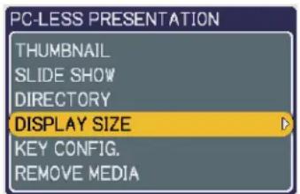
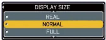
4) Select your desired DISPLAY SIZE.
- REAL : Displays the image at original size. Displays the image at the center of screen if original size is smaller than the screen size. Displays only center of the image if original size is larger than the screen size.
- NORMAL : Displays the image for the maximum size on the screen, and keeps original aspect.
- FULL : Displays the image at the full size screen. Original aspect will be changed to full size display.
The animation file is always played at VGA mode if resolution is larger than VGA. The animation file is always played at the center of screen if resolution is smaller than VGA.
You can select the KEY configuration from 2 preset pattern assigned to ▲/▼/◄/► keys on Tumbnail Mode.
1) Select the KEY CONFIG. in PC-LESS PRESENTATION menu.
2) Press ▶ button.
3) The KEY CONFIG. menu appears.
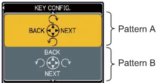
flowchart
graph TD
    A["KEY CONFIG."] --> B["BACK"]
    B --> C["NEXT"]
    C --> D["Pattern A"]
    A --> E["BACK"]
    E --> F["NEXT"]
    F --> G["Pattern B"]
4) Select the KEY CONFIG. pattern.
- pattern A : ◀: previous image ▶: next image
▲ : rotation to right ▼ : rotation to left - pattern B : ◀ : rotation to left ▶ : rotation to right
▲ : previous image ▼ : next image
5.4 Slide Show Mode
You can play the Slide show with the projector menu. Select the SLIDE SHOW on PC-LESS PRESENTATION menu and press the ENTER / ▶ button on the remote control or ▶ button on Keypad. Then Slide show will start.
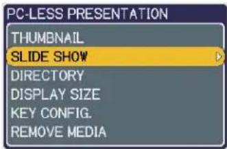
You can also play the Slide show by clicking [SLIDE SHOW] button in the Web Remote Control.
The Slide Show Mode (Fig. 5.4) displays a full screen image and switches the images at intervals set in the Display time. The Display time can be set by the Playlist (116) and menu. (111)
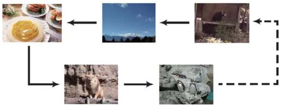
flowchart
graph TD
    A["Food and Animal Images"] --> B["Mountain Scavings"]
    B --> C["Beef and Grassland"]
    C --> D["Landscape with Mountain"]
    D --> E["Forest and Wildlife"]
    E --> F["Outdoor Environment"]
    F --> G["Environment"]
    G --> H["Environment"]
    H --> I["Environment"]
    I --> J["Environment"]
    J --> K["Environment"]
    K --> L["Environment"]
    L --> M["Environment"]
    M --> N["Environment"]
    N --> O["Environment"]
    O --> P["Environment"]
    P --> Q["Environment"]
    Q --> R["Environment"]
    R --> S["Environment"]
    S --> T["Environment"]
    T --> U["Environment"]
    U --> V["Environment"]
    V --> W["Environment"]
    W --> X["Environment"]
    X --> Y["Environment"]
    Y --> Z["Environment"]
    Z --> A
Fig. 5.4 Slide Show Mode
The following operations can be accessible while the Slide show is displayed.
| Button operation | Functions | ||
| The remote control | The keypad on the projector | Web Remote in web browser software. | |
| ENTER INPUT | ENTER Displays thumbnail. | ||
| MENU - MENU | Displays PC-LESS PRESENTATION menu. | ||
* These operations are not accessible while the projector OSD menu is displayed.
NOTE • It is impossible to change the input port by the INPUT button if the THUMBNAIL, SLIDE SHOW, or DIRECTORY is displayed.
- Display the projector OSD menu before changing the input port.
- Images can be displayed when it is recorded in the playlist.
- Image can not be displayed in the thumbnail if it is not recorded in the playlist. (116)
- When the SLIDE SHOW mode is set to ONE TIME, the last slide of the presentation will be held on screen till the ENTER button on the remote control or Web Remote Control, or INPUT button on the projector is pushed.
5.4 Slide Show Mode (continued)
You can play the Slide show at your desired configuration. Configure the SLIDE SHOW items in THUMBNAIL.
1) START # : Set the beginning number of the Slide show.
2) STOP # : Set the end number of the Slide show.
3) INTERVAL : Set the interval time of the Slide show.
4) MODE : Select the Slide show mode.
ONE TIME : Play the Slide show one time.
ENDLESS : Play the Slide show endless.
5) PLAY : Play the Slide show.
It is not recommend to set the interval time very short something like several seconds, because it may take more than several seconds to read and display an image file if it is stored in very deep layer directory or if so many files are stored in the same directory.
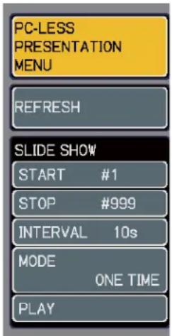
NOTE • The settings of the Slide Show are saved to the “slidemode.txt” file that is stored in the storage media. If the file is not existed, it is generated automatically.
- The START #, STOP #, INTERVAL, and MODE are set by thumbnail menu once, this setting has more priority than the Playlist.
- If the storage media is under the write protection or the “slidemode.txt” is the read only type file, it is impossible to change the settings of the Slide Show.
- If you would like to release the priority, delete the “slidemode.txt” file from directory.
5.5 Directory Tree View
You can display the directory with the projector menu. Select the DIRECTORY on the PC-LESS PRESENTATION menu. And press the ENTER / ▶ button on the remote control or ▶ button on Keypad. Then directory will be displayed.
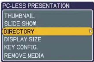
You can also display the directory by clicking [DIRECTORY] button in the Web Remote Control.
The Directory Tree View (Fig. 5.5) displays all folders and files (includes unsupported format file) in the memory card as a tree view.
The preview image is shown on the top left corner on the directory tree view. In case of movie file, an initial flame is displayed as preview. No preview is displayed if a folder or un-supported format file is selected.
If the displayable file is selected and the ENTER button on remote control is pressed, it turns into the full screen image.
If the directory is selected and the ENTER button on remote control is pressed, it turns into the thumbnail view of selected folder.
You can also display the full screen image or the thumbnail view by clicking [ENTER] button in the Web Remote Control.
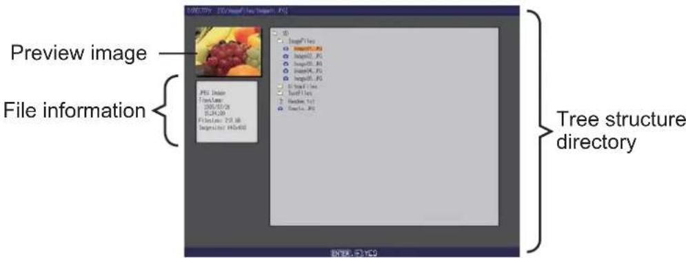
Fig. 5.5 Directory Tree View
5.5 Directory Tree View (continued)
The following operations can be accessible while directory is displayed.
| Button operation | Functions | ||
| The remote control | The keypad on the projector | Web Remote in web browser software. | |
| ▲/▼ ▲/▼ UP/DOWN | Moves selected item upward or downward. | ||
| ► ► RIGHT | Opens the closed folder. | ||
| ◄◄ LEFT | Closes the folder. | ||
| PAGE UP PAGE DOWN | - | PAGE UP PAGE DOWN | Switches pages if the whole directory tree view cannot be displayed. |
| ENTER INPUT ENTER | Displays a selected file as a preview in full screen. The un-supported format file cannot be opened. If the preview is displayed and Enter button is pressed, it returns to the directory tree view. If the directory (folder) is selected, it turns into Thumbnail Mode. | ||
| MENU - MENU Displays the menu. | |||
* These operations are not accessible while projector OSD menu is displayed.
NOTE • It is not possible to change the input port by INPUT button when THUMBNAIL, SLIDE SHOW, or DIRECTORY is displayed.
- Display the projector OSD menu before changing the input port.
- Only alphanumeric characters can be used for directory name and file name.
- This Directory Tree View is able to show up to 10 layers depth. The files and folders that located on more than 10th layer cannot be shown. Some files and directories are not displayed if there are too many. In this case, delete some files in the directory or some directories in the memory card.
5.5 Directory Tree View (continued)
[File information display]
In the Directory Tree View screen, the following information is shown as the File information.
Picture file (still picture)
- File format ("JPEG Image", "PNG Image" or "BMP Image")
- Time stamp (When file is created)
- File size (Size of File)
- Image size (File resolution)
Movie file (motion picture)
- File format ("MP4 Movie")
- Time stamp (When file is created)
- File size (Size of File)
- Movie size (File resolution)
- Movie time (Play time)
Un-supported format file
- File format ("File")
- Time stamp (When file is created)
- File size (Size of File)
Directory
- File format ("Directory")
- Time stamp (When directory is created)
5.6 "PC-LESS Presentation" error message
Error message is displayed at a specific condition while "PC-LESS Presentation" mode. It appears at the bottom and the gray area of screen.
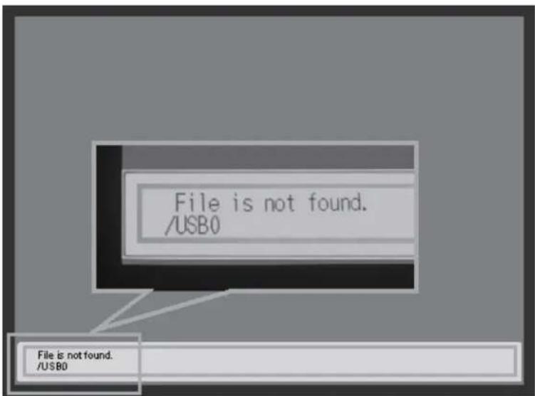
Fig. 5.6 "PC-LESS Presentation" error message
"PC-LESS Presentation" error message list
| Error message Error content Display mode | ||
| File is not found. Displayable file does not exist. | The Full Screen Mode (from Thumbnail Mode) and Side Show Mode | |
| Illegal Playlist file. | The Playlist file has malfunction.(Over 64kB file, over 1022 characters per line in file or linefeed code malfunction) | The Slide Show Mode |
5.7 Playlist
The Playlist is a DOS format text file, which decides the order of displayed still image files or moving image files in the thumbnail or the slide show.
The playlist file name is "imagelistdir.txt". It is created in each folder when the PC-LESS Presentation is displayed. The timing of playlist creation is when PC-LESS Presentation is displayed in the directory, which any playlist file does not exist. The playlist is created in the displayed directory.
The playlist is editable on the PC. Display time and rotation information at the slide show can be set based on specifying settings. Of course it is possible to make certain file image undisplayable in a playlist deleting 1 line relating to the file from playlist. Also, it is possible to see added picture image based on adding picture image file name and pass name of destination to save in playlist.
[Example of adding image file]
(Pass name/pass name/.../file name, display time, rotation information)
images/photo1/img001.jpg
images/photo1/img002.jpg, 2000
images/photo1/img003.jpg, 500, rot1
images/photo1/img004.jpg
images/photo1/img005.jpg, 500, rot2
The number after the extension is the slide show display time. It can be set between 0 and 999900. (ms) Least input increment is 100 ms. The end of display time means rotation information. 90 degrees clockwise rotation becomes rot1, rot2 and rot3. (When no rotation, not specify or specify rot0.)
Display time and rotation information should be used “,” for separation.
⚠️ CAUTION • Maximum characters for the playlist in 1 line at playlist is 1024 including linefeed. If it exceeds, playlist becomes invalid and error.
- Playlist maximum size is 64kB. If it exceeds, it becomes invalid.
- Playlist can register up to 999 image files. If it exceeds, first 999 files can be utilized.
-
When image file is added to the memory card and be able to see on the screen, delete existing playlist in the memory card.
-
Troubleshooting
| Problem Likely Cause Things to Check | Reference Page Number | ||||
| No image | The projector is not turned on. | Is the projector's lamp on? | *17 | ||
| The projector's input source isn't switched to MIU. | Is the projector switched to MIU? | *18 | |||
| Wireless / Wired | Live Mode | The projector that you want to connect to is nowhere to be found on the list of available projectors | The PC and/or projector's network settings are not configured correctly. | Check both the PC and projector's network settings. If you change the projector's settings, turn off the projector's AC power and then turn it on again. If you simply put the projector in STANDBY power mode and then turn it on again, the new settings might not take effect. | 10 |
| Weak radio signal | Bring the PC and projector closer together.Radio waves won't go through concrete and metal (steel doors, etc.) | - | |||
| Can't communicate | The Projector isn't in Live Mode | Check the mode on MIU menu to make sure that it is in the correct mode. | *55 | ||
| WPA-PSK or/and WPA2-PSK is not configure correctly in Windows® 2000 or Windows® XP/XP SP1/XP SP1a. | In Windows® 2000 and Windows® XP/XP SP1/XP SP1a,WPA-PSK and WPA2-PSK could not configure via LiveViewer 3. Use wireless configuration utility with PC or wireless adapter. Please refer the manual of your configuration utility. If you are using Windows® XP/XP SP1/XP SP1a, you can configure WPA-PSK and WPA2-PSK by updating to SP2 or later | - | |||
| Cannot communicate due to configure wireless / encryption settings | If there is a wireless configuration utility loaded on your PC, check the configuration settings of it. Please refer the manual of your configuration utility. | - | |||
| Configuration network settings of LiveViewer may not be set correctly. | Be sure that the configuration settings of LiveViewer are correct for usage with your PC or wireless adapter. | 10 | |||
(continued on next page)
* Operator's Guide
- Troubleshooting (Continued)
| Problem Likely Cause Things to Check | Reference Page Number | ||||
| Wireless / Wired | Live Mode | The projected image is rather slow compared to that of the PC | The projector isn't capable of relaying dynamic images such as PowerPoint® animation at full speed. | Switching the priority to 'Transmission Speed' under the options menu may help to improve speed. | 58 |
| The compression rate being used for transferring the images is too low. | Switching the priority to 'Transmission Speed' under the options menu may help to improve speed. | 58 | |||
| No Image | Using Photo Gallery Slide Show in Windows® Vista. | LiveViewer 3 cannot send PC screen data while using Windows® Vista Photo Gallery Slide Show. Please close Photo Gallery Slide Show before using LiveViewer 3. | - | ||
| Can't display the movies correctly. | In some combinations of PC's video card and application software, there is a possibility that true image - especially movies played by media player - cannot be transferred to the projector with Live Viewer 3. | If there is a video acceleration level adjustment function in your application, please try to adjust it. Refer your application manual in detail. | - | ||
| PC-Projector network connection is disconnected when PC display resolution is changed while displaying Live Mode. | PC-Projector network connection might be disconnected when PC display resolution is changed while displaying picture. | Please re-connect using "Starting Capture button" after changing PC display resolution, or change display resolution before connecting with the Live Viewer 3. | 54 | ||
| Images contain lots of interference. | The compression rate being used for transferring the images is too high. | Try setting the priority to 'Image Quality' in the LiveViewer 3 Option menu. You may experience a drop in speed. | 58 | ||
| Two cursors appear | Cursor of the PC and cursor of the projector are displayed coming in succession. | Turn off the cursor Emulation of "Live Viewer 3" option. | 58 | ||
| No cursor appears | Some PCs do not display the cursor in "Live Viewer 3". | Turn on the cursor Emulation of "Live Viewer 3" option. | 58 | ||
| Neither transparency nor translucency effects (Glass) | Using LiveViewer 3 with Windows Aero mode. | LiveViewer 3 does not support these features of Windows® Vista Aero. | - | ||
(continued on next page)
- Troubleshooting (Continued)
| Problem Likely Cause Things to Check | Reference Page Number | |||
| PC-LESS | No information is shown after mass storage device is set on Thumbnail or Directory mode. | The mode setting is not renewed after the device is set. | Select either Thumbnail mode or Directory mode again, showing PC-LESS Presentation menu. | 104, 112 |
| Wireless | Can't communicate | The wireless network card isn't inserted into the projector or the memory card is still inserted. | Insert the wireless network card that came with your projector into the module. | *12 |
| There is closely another projector or other that has the same wireless setting. | Try changing of SSID and IP Address. | 70 *60 | ||
| Wired LAN | Can't communicate | The PC and/or projector's network settings are not configured correctly. | Check both the PC and projector's network settings. | 11-14, 41 |
| The wireless network card is inserted into the projector. | Remove the SD wireless network card from the projector (you can't use both wireless and wired LAN connections at the same time). | *58 | ||
| Others- Information from the projector to PC is not correct or completed- The projector does not respond- Image on screen is frozen. | Communication between the projector and PC is not working well.MIU Functions of the projector is not working well. | Try “MIU RESTART” in SERVICE menu under the MIU menu. | *63 | |
* Operator's Guide
7. Specifications
- Specifications
| Item Specifications | |
| File format JPEG, PNG, Bitmap and MPEG4 | |
| Control software Dedicated PC application and Web browser | |
| Corresponding protocol | TCP/IP, DHCP client and HTTP server |
| Network | Wireless LAN (IEEE802.11b/g)(Ad-Hoc and Infrastructure modes)Ethernet (100Base-TX/10Base-T) |
| Security WEP (64/128bit), WPA-PSK/PSK2 (TKIP/AES), SSID | |
| PC application operational environment | OS: Windows® 2000 Professional (Service Pack4)Windows® XP Home EditionWindows® XP ProfessionalWindows® Vista Home Basic (32bit)Windows® Vista Home Premium (32bit)Windows® Vista Business (32bit)Windows® Vista Enterprise (32bit)Windows® Vista Ultimate (32bit)CPU: Pentium® III 600MHz or more is recommended.Memory size: 64MB or more,128MB or more in case of XPVideo RAM: 4MB required (8MB recommended)HDD: 20MBCD-ROM driveWeb browser: Internet Explorer® 5.5 or later |
| SD Memory Card SD M | Memory Card (Corresponding card is not confirmed yet.) |
| Wireless network card C-guys SD-Link11g | |
| USB | USB1.0 host mass storage class SBC/BOT typeFollowing USB memories can be read/written.- USB memory type- Card reader type(Corresponding card is not confirmed yet.) |
8. Warranty and after-sales service
If a problem occurs with the equipment, please read "6. Troubleshooting" (117) section first and review all suggested check points. After that, please contact your dealer or service company, if you still have the problem. They will tell you what warranty condition is applied.
Important Notice
All statements, technical information, and recommendations related to 3M's products are based on information believed to be reliable, but the accuracy or completeness is not guaranteed. Before using this product, you must evaluate it and determine if it is suitable for your intended application. You assume all risks and liability associated with such use. Any statements related to the product which are not contained in 3M's current publication, or any contrary statements contained on your purchase order shall have no force or effect unless expressly agreed upon, in writing, by an authorized officer of 3M.
Warranty
3M warrants that when the 3M Product is used according to 3M's Intended Use Statement (www.3M.com/meetings), it will perform satisfactorily for the warranted durability period as stated in the applicable 3M Product Manual in effect at the time of purchase. The warranties stated in the applicable 3M Product Manuals are exclusive and are made in place of any and all express or implied warranties or conditions, including any implied warranty of merchantability or fitness for a particular purpose, or any industry practice or custom or trade usage.


http://www.3m.com/meetings e-mail: meetings@mmm.com
3M Austin Center
Building A145-5N-01
6801 River Place Blvd.
Austin, TX 78726-9000
3M Canada
P.O. Box 5757
London, Ontario
N6A 4T1
3M Mexico, S.A. de C.V.
78-6971-1486-2 Rev. A
- Thank you for purchasing this projector.
- √ Live Mode
- √ Quick connection to your network
- √ Web control
- √ PC-LESS Presentation
- NOTE • The information in this manual is subject to change without notice.
- Trademark acknowledgment
- Content
- [Non-Text]
- Content 2
- Caution 3
- Main functions ..... 5
- Equipment connection and network setting .. 1 0
- Using the Live Mode ..... 2 0
- Management with Web browser software..64
- PC-LESS Presentation....102
- Troubleshooting ..... 11 7
- Specifications ..... 1 2 0
- Warranty and after-sales service..121
- Caution
- [Restriction in terms of inserts or pulls storage media and wireless network card]
- Main functions
- Live Mode (Project images from PC)
- Quick connection to your network
- 1) Quick connection by the Passcode
- 2) Connection by the profile for the network
- 3) Connection by the history record for the network
- Configuring and controlling via a web browser
- PC-LESS Presentation
- (Display the images stored in SD memory card/USB memory.)
- [Supported storage media]
- NOTE • There are several naming limitations for the folders and files.
- Equipment connection and network setting
- Required equipment preparation
- Quick connection
- Manual network connection setting - Wired LAN -
- Equipments connection
- Network settings
- Manual network connection setting - Wired LAN - (continued)
- [About IP address]
- ■ Setting manually
- For example
- NOTE • “0.0.0.0” cannot be set to the IP address.
- ■ Setting automatically
- "Internet Option" setting
- Check connection
- Manual network connection setting -Wireless LAN
- Preparation for wireless LAN connection
- Manual network connection setting -Wireless LAN (continued)
- Wireless LAN connection set up
- 7) Set each item as follows.
- Using the Live Mode
- Outline of the Live Mode
- Display mode
- Outline of the Live Mode (continued)
- Presenter mode
- Display User Name
- Install "Live Viewer 3"
- Minimum PC hardware and software requirement
- Install "Live Viewer 3" (continued)
- Software Installation Procedure
- Version of the "Live Viewer" software
- Quick connection to the network
- Starting the "Live Viewer 3"
- Quick connection to the network (continued)
- Selecting the network connection mode
- Selecting either the wireless LAN or wired LAN
- [trouble shooting]
- Selecting the My Connection
- Connecting to the network
- Enter PassCode
- Configure Manually
- Configuring manually (43)
- Select From List
- Passcode connection
- Getting the Passcode
- Method 1
- Passcode connection (continued)
- Method 2
- Entering the Passcode
- Configuring manually
- Wireless LAN
- Direct connection between the projector and PC (AdHoc mode)
- The projector connected to an access point by a LAN cable
- The projector connected to an access point by the wireless LAN
- Wired LAN
- Manual configuration
- Profile connection
- Manual configuration (continued)
- History connection
- Configuring manually
- Confirm the connection to your destination
- Connection and transmission
- Confirm the connection to your destination (continued)
- Connection error
- Setting the Live Mode
- From Web Remote Control on a web browser
- From the OSD menu, by using the remote control or keypad on the projector.
- From MY BUTTON function
- Start the "Live Viewer 3"
- Main menu and Operating buttons
- 1) Menu Type
- 2) Operating buttons
- q Starting Capture button
- w Stop button
- Start the "Live Viewer 3" (continued)
- e Hold button
- r Display mode button (57)
- t Connect button
- y Option button
- u Information button
- i, o Close button
- a Minimize button
- Displaying the status
- 1) Indicator
- 2) Status Display in Multi PC mode
- Switching the display mode
- Option menu
- q Optimize Performance
- Transmission speed
- Image quality
- w Cursor Emulation
- e Presenter Mode
- r Display User Name
- Profile data
- Outline of Profile data
- Making Profile data
- Profile data (continued)
- Editing Profile data
- Registering My Connection
- Management with Web browser software
- Confi guring and controlling the projector via a web browser
- E-mail Alerts
- Projector Management using SNMP
- Event Scheduling
- MY IMAGE (Still Image Transfer) Display
- Command Control via the Network
- Configuring and controlling the projector via a web browser
- NOTE • Internet Explorer® 5.5 or later is required.
- Configuring and controlling the projector via a web browser (Continued)
- Logon
- Network Information
- Network Settings
- Port Settings
- Mail Settings
- Alert Settings
- Schedule Settings
- Date/Time Settings
- Security Settings
- Projector Control
- Remote Control
- Projector Status
- Network Restart
- Item Description
- Restart
- Logoff
- E-mail Alerts
- Mail Settings (72)
- E-mail Alerts (Continued)
- Projector Management using SNMP
- SNMP Settings (71)
- Event Scheduling
- Event Scheduling (Continued)
- Schedule Settings (75)
- Date/Time Settings (77)
- MY IMAGE (Still Image Transfer) Display
- NOTE • Supported file types are JPEG, Bitmap and PNG.
- Command Control via the Network
- Communication Port
- Command Control Settings (71)
- Command Control via the Network (Continued)
- Command Format
- Send Data format
- Reply Data format
- Automatic Connection Break
- Authentication
- PC-LESS Presentation
- Outline of the PC-LESS Presentation
- Outline of the PC-LESS Presentation (continued)
- [Supported format]
- [Supported file format]
- Thumbnail mode
- Starting the Thumbnail mode
- from the OSD menu
- Thumbnail mode (continued)
- from a web browser software
- Operating by buttons or keys
- Operation on the Thumbnail menu
- Full Screen Mode
- Full Screen Mode (continued)
- Slide Show Mode
- Slide Show Mode (continued)
- Directory Tree View
- Directory Tree View (continued)
- [File information display]
- Picture file (still picture)
- Movie file (motion picture)
- Un-supported format file
- Directory
- "PC-LESS Presentation" error message
- Playlist
- [Example of adding image file]
- Specifications
- Warranty and after-sales service
- Important Notice
- Warranty
Brand : 3M
Model : X95i
Category : Projector