
824TDW - Dimmer JUNG - Free user manual and instructions
Find the device manual for free 824TDW JUNG in PDF.


| Product Type | Tronic Rotary Dimmer |
| Model | 824 TDW |
| Rated Voltage | AC 230 V ~, 50 Hz |
| Ambient Temperature | +5 ... +25 °C |
| Connected Load (Incandescent / HV Halogen / Tronic Transformers) | 20 ... 400 W |
| Power Reduction (surface-mounted) | 20 ... 400 W (same as rated) |
| Power Reduction (per 5°C above 25°C) | -10% |
| Power Reduction (wooden/dry construction walls) | -20% |
| Power Reduction (multiple combinations) | -20% |
| Connection | Single stranded 1.0 ... 2.5 mm², stripping length 15 mm |
| Control Output A | 100 mA max |
| Dimming Principle | Phase cut-off (trailing edge) |
| Short-Circuit Protection | Electronic, automatic switch-off after ≤7 s |
| Over-Temperature Protection | Electronic, automatic switch-off and reactivation after cooling |
| Changeover Switching | Possible with external changeover switch |
| Mounting | In appliance box according to DIN 49073 |
| Dimensions (approx.) | Standard flush-mount (71 x 71 x 45 mm) |
| Weight (approx.) | 0.1 kg |
| Maintenance | Wipe with a dry cloth; do not use cleaning agents |
| Safety Instructions | Disconnect power before installation; not for electronic lamps (LED/CFL) |
| Spare Parts | Control button, frame, central plate (order separately) |
| Reparability | Send to manufacturer service center for repair |
Frequently Asked Questions - 824TDW JUNG
User questions about 824TDW JUNG
0 question about this device. Answer the ones you know or ask your own.
Ask a new question about this device
Download the instructions for your Dimmer in PDF format for free! Find your manual 824TDW - JUNG and take your electronic device back in hand. On this page are published all the documents necessary for the use of your device. 824TDW by JUNG.
USER MANUAL 824TDW JUNG
Tronic rotary dimmer for Tronic transformers
Art.-No.: 225 TDE
Tronic rotary dimmer for Tronic transformers
Art.-No.: 824 TDW
Operationsmanual
1 Safety instructions
Electrical equipment may only be installed and fitted by electrically skilled persons.
Failure to observe the instructions may cause damage to the device and result in fire and other hazards.
Always disconnect before carrying out work on the devise or load. At the same time, take into account all circuit breakers that supply dangerous voltage to the device or load.
The device is not suitable for disconnection from supply voltage.
Do not connect electronic lamps, e.g. switchable or dimmable energy-saving lamps or LED lamps. Otherwise the possibility of a device defect cannot be ruled out.
These instructions are an integral part of the product, and must remain with the end customer.
2 Device components
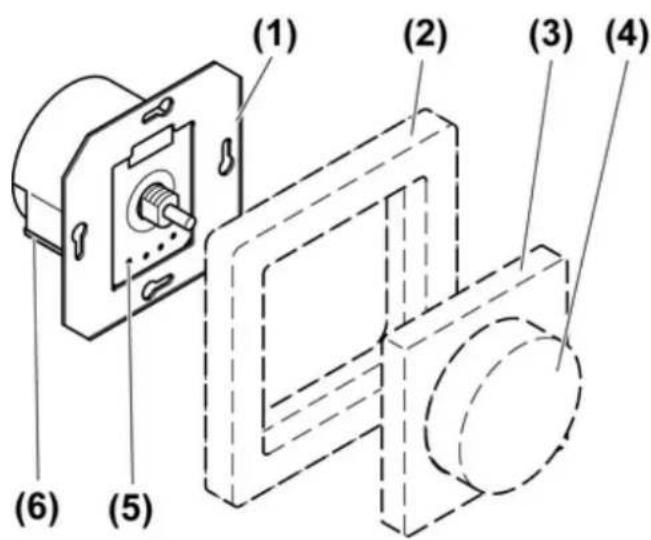
picture 1: Device components
(1) Dimmer
(2) Frame
(3) Central plate
(4) Control button
(5) Measuring points for voltage test
(6) Release lever for plug terminal
3 Function
Intended use
- Switching and dimming incandescent lamps, HV halogen lamps and Tronic-transformers with halogen lamps.
- Suitable for mixed operation up to the specified output (see chapter 6.1. Technical data).
- Installation in appliance box acc. to DIN 49073.
i No operation with inductive transformers.
Product characteristics
- Dimming principle, phase cut-off.
- Soft locking on operation
- Electronic short-circuit protection with permanent switch-off after 7 seconds at the latest
- Electronic over-temperature protection
- Changeover switching possible in combination with changeover switch
- Control output A to output the switching status of the device to control automatic power disconnection or relay.
i Control output A may not be used as a load output.
i Flickering of the connected lamps due to undershoot of the specified minimum load or through centralised pulses from the power stations. This does not represent any defect in the device.
4 Operation
Switch light
■ Press the control button.
Adjust the brightness
Light is switched on.
■ Turn the control button in the clockwise direction.
The light gets brighter up to maximum brightness.
■ Turn the control button in the anti-clockwise direction.
Light gets darker to minimum brightness.
5 Information for electrically skilled persons
5.1 Fitting and electrical connection

DANGER!
Electrical shock when live parts are touched.
Electrical shocks can be fatal.
Before carrying out work on the device or load, disengage all the corresponding circuit breakers. Cover up live parts in the working environment.
Connecting and mounting the dimmer
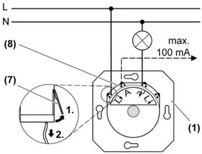
picture 2: Connection diagram
(1) Dimmer
(7) Pull the connecting cable out of the push terminal.
(8) Control output A
■ Remove approx. 15 mm of insulation from the connecting cables.
■ Connect the dimmer according to the connection diagram (picture 2).
■ Fit dimmer in appliance box, connection terminals must be at the bottom.
■ Mount the frame and the central plate.
■ Attach the control button.
Connection in changeover switch
i No changeover switch possible with two dimmers.
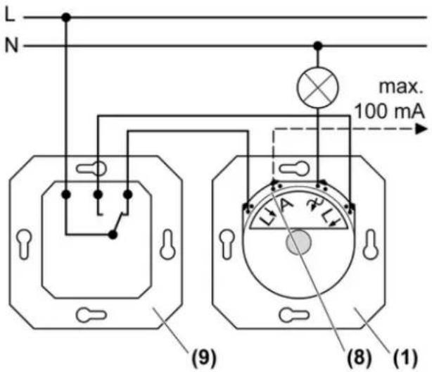
picture 3: Changeover switch
(1) Dimmer
(8) Control output A
(9) Changeover switch
■ Connect the dimmer (1) and the changeover switch (9) according to the connection diagram (picture 3).
6 Appendix
6.1 Technical data
Rated voltage AC 230 V \~
Mains frequency 50 Hz
Ambient temperature +5 ... +25 °C
Connected load at 25 °C
i Power specifications including transformer power dissipation.
Incandescent lamps
Art.-No.: 225 TDE 20 ... 525 W
Art.-No.: 824 TDW 20 ... 400 W
HV halogen lamps
Art.-No.: 225 TDE 20 ... 525 W
Art.-No.: 824 TDW 20 ... 400 W
Tronic transformers
Art.-No.: 225 TDE 20 ... 525 W
Art.-No.: 824 TDW 20 ... 400 W
ohmic-capacitive
Art.-No.: 225 TDE 20 ... 525 W
Art.-No.: 824 TDW 20 ... 400 W
Power reduction
when surface-mounted
Art.-No.: 225 TDE 20 ... 500 W
Art.-No.: 824 TDW 20 ... 400 W
per 5°C in excess of 25°C -10 %
when installed in wooden or dry construction
walls
when installed in multiple combinations -20 %
Connection
Single stranded 1.0 ... 2.5 mm²
Stripping length 15 mm
Power boosters See power booster instructions
Control output A
Current carrying capacity 100 mA

The symbols used to label the dimmer load shows the load type that can be connected to a dimmer and the electric behaviour of a load:
R = ohmic, C = capacitive
6.2 Troubleshooting
The device switches the load off and only on again after some time.
Overheating protection has tripped.
Reduce the connected load.
Check the installation situation.
The device switches the load off briefly and then on again.
Short-circuit protection has tripped but now there is no longer a fault.
The device switches the load off and cannot be switched on again.
Short-circuit protection has tripped.
Eliminate short-circuit.
Switch the dimmer back on by pressing the control knob twice.
i Short-circuit protection is not based on a conventional fuse, no metallic separation of the operational current.
6.3 Warranty
We reserve the right to make technical and formal changes to the product in the interest of technical progress.
We provide a warranty as provided for by law.
Please send the unit postage-free with a description of the defect to our central customer service office:
ALBRECHT JUNG GMBH & CO. KG
Service Center
Kupferstr. 17-19
D-44532 Lünen
Service-Line: +49 (0) 23 55 . 80 65 51
Telefax: +49 (0) 23 55 . 80 61 89
mail.vka@jung.de
General equipment
Service-Line: +49 (0) 23 55 . 80 65 55
Telefax: +49 (0) 23 55 . 80 62 55
mail.vkm@jung.de
KNX equipment
Service-Line: +49 (0) 23 55 . 80 65 56
Telefax: +49 (0) 23 55 . 80 62 55
mail.vkm@jung.de
The C€ symbol is a free trade symbol, which is solely intended for the authorities and does not guarantee any properties.
ALBRECHT JUNG GMBH & CO. KG
Vollmestraße 1
- Operationsmanual
- Safety instructions
- Device components
- Function
- Intended use
- Product characteristics
- Operation
- Switch light
- Adjust the brightness
- Information for electrically skilled persons
- Fitting and electrical connection
- DANGER!
- Connecting and mounting the dimmer
- Connection in changeover switch
- Changeover switch
- Appendix
- Technical data
- Troubleshooting
- Warranty
- ALBRECHT JUNG GMBH & CO. KG
- General equipment
- KNX equipment
Brand : JUNG
Model : 824TDW
Category : Dimmer