LS1565.07 - Dimmer JUNG - Free user manual and instructions
Find the device manual for free LS1565.07 JUNG in PDF.

| Product Type | Dimmer |
| Brand | JUNG |
| Model | LS1565.07 |
| Dimensions (HxWxD) | 71 x 71 x 32 mm |
| Weight | 80 g |
| Rated Voltage | 230 V AC, 50/60 Hz |
| Maximum Load (Incandescent) | 400 W |
| Maximum Load (LED) | 100 W |
| Operation | Rotary knob for dimming and switching |
| Installation | Flush-mounted in wall box |
| Material | Thermoplastic, impact-resistant |
| Color | White (standard) |
| Protection Rating | IP20 |
| Protection Class | II (double insulated) |
| Operating Temperature | -5°C to +45°C |
| Compatible Load Types | Incandescent, halogen, LED, CFL (dimmable) |
| Minimum Load (LED) | 5 W |
| Standby Power Consumption | < 0.5 W |
| Cleaning | Wipe with a soft, damp cloth; no solvents |
| Safety Notes | Install by qualified electrician; disconnect power before servicing |
| Spare Parts | Not available; replace entire unit if defective |
| Repairability | Non-repairable; sealed unit |
Frequently Asked Questions - LS1565.07 JUNG
User questions about LS1565.07 JUNG
0 question about this device. Answer the ones you know or ask your own.
Ask a new question about this device
Download the instructions for your Dimmer in PDF format for free! Find your manual LS1565.07 - JUNG and take your electronic device back in hand. On this page are published all the documents necessary for the use of your device. LS1565.07 by JUNG.
USER MANUAL LS1565.07 JUNG
Universal 2-gang dimmer insert
Art.-No.: 1252 UDE
Operating instructions
1 Safety instructions
Electrical equipment may only be installed and fitted by electrically skilled persons.
Serious injuries, fire or property damage possible. Please read and follow manual fully.
Danger of electric shock. Do not operate the device without a cover.
Danger of electric shock. Always disconnect before carrying out work on the devise or load. At the same time, take into account all circuit breakers that supply dangerous voltage to the device or load.
Danger of electric shock. Device is not suitable for disconnection from supply voltage. The load is not electrically isolated from the mains even when the device is switched off.
Fire hazard. For operation with inductive transformers, each transformer must be fused on the primary side in accordance with the manufacturer's instructions. Only safety transformers according to EN 61558-2-6 may be used.
Exchange defective load on output a1 immediately, because the overheating protection is no longer provided when the load is defective. Device can be damaged.
These instructions are an integral part of the product, and must remain with the end customer.
2 Device components

text_image
(1) (2) (3) (4)Figure 1: Device components
(1) Dimmer
(2) Frame
(3) Cover (see chapter 6.3. Accessories)
(4) Screw terminals
3 Function
Intended use
- Switching and dimming of incandescent lamps, HV halogen lamps and dimmable inductive transformers or Tronic transformers with halogen lamps
- Suitable for mixed load up to the specified output (see chapter 6.1. Technical data)
- Suitable for luminaire groups via the two independent outputs a1 and a2
- Installation in appliance box to DIN 49073
- Operation with suitable cover (see chapter 6.3. Accessories)
i No mixed-load operation of Tronic and inductive transformers on the same output.
Product characteristics
- Electronic short-circuit protection with permanent switch-off after 7 seconds at the latest
- Electronic over-temperature protection
- Bulb-preserving soft start
- Power extension through power boosters (see power booster instructions)
- Different load types are possible on the two outputs
- Asymmetric load distribution possible
- Automatic setting of the dimming principle suitable for the load
- Connection of more than one 2-wire extension is possible (see Accessories section)
i The connection of installation buttons as extensions is not possible. This will not function.
| Load type Electrical behaviour Dimming principle | |
| Incandescent lamps ohmic Phase cut-off | |
| HV halogen lamps ohmic Phase cut-off | |
| Tronic transformers with halogen lamps | capacitive Phase cut-off |
| Dimmable inductive transformers with halogen lamps | inductive Phase cut-on |
i Flickering of the connected lamps due to undershoot of the specified minimum load or through centralised pulses from the power stations. Brief flickering upon load detection of ohmic loads. No operation is possible during load detection. These are not device faults.
4 Operation

text_image
a1 a2Figure 2: Operating sections of the button
The button field is subdivided into two areas:
- Left: operation of output a1.
- Right: operation of output a2.
i A 2-wire extension is always used to operate both outputs simultaneously.
Switching on the light
■ Press button at top for less than 0.4 seconds.
i The light is switched on using the stored switch-on brightness.
Switching the light off
■ Press button at bottom for less than 0.4 seconds.
Adjust the brightness
Light is switched on.
■ Press up or down button until the desired brightness is reached.
Switching the light on with minimum brightness.
Light is switched off.
■ Press button at bottom for longer than 0.4 seconds.
Save switch-on brightness
Separate switch-on brightnesses can be saved for outputs a1 and a2. In the state as supplied the maximum switch-on brightness is saved.
Light is switched on.
■ Set light to the required brightness.
■ Press button for longer than 3 seconds.
Switch-on brightness is saved.
The lighting switches briefly off and on again as confirmation.
5 Information for electrically skilled persons
5.1 Fitting and electrical connection

DANGER!
Electrical shock when live parts are touched.
Electrical shocks can be fatal.
Before carrying out work on the device or load, disengage all the corresponding circuit breakers. Cover up live parts in the working environment.

CAUTION!
Do not connect outputs together.
Operating both outputs on a common load will destroy the device.
For power extension use power boosters

CAUTION!
Electronic overheating protection only with active output a1.
Operation without electronic overheating protection can destroy the device.
Never operate output a2 alone.
Connecting and mounting the dimmer
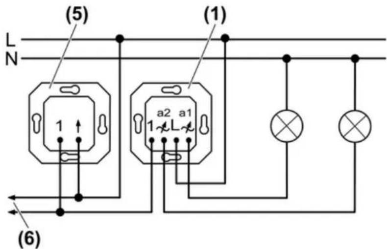
Figure 3: Connection diagram
(1) Dimmer
(5) 2-wire extension
(6) to additional extensions
i Output a1 can also be operated alone.
Pay attention to load distribution when an output is loaded with more than 260 W/VA(see chapter 6.1. Technical data). Determine intermediate values by means of interpolation.
■ Connect the dimmer according to the connection diagram (figure 3).
■ If multiple miniature circuit breakers supply dangerous voltages to the device or load, couple the miniature circuit breakers or label them with a warning, to ensure release is guaranteed.
■ Mount the dimmer in an appliance box. The terminals must be at the bottom.
■ Attach the frame and the cover.
6 Appendix
6.1 Technical data
Rated voltage AC 230 V \~
Mains frequency 50 / 60 Hz
Ambient temperature +5 ... +25 °C
Connected load per output at 25°C
Incandescent lamps 50 ... 260 W
HV halogen lamps 50 ... 260 W
Tronic transformers 50 ... 260 W
Inductive transformers 50 ... 260 VA
Ohmic-inductive 50 ... 260 VA
ohmic-capacitive 50 ... 260 W
capacitive-inductive not permitted
i Operate inductive transformers with at least 85% nominal load.
i Power specifications including transformer power dissipation.
For ohmic-inductive mixed load, maximum 50% proportion of ohmic load. Otherwise incorrect calibration of the dimmer may result.
Load distribution at 25 °C
| Output a1 Output a2 | |
| 350 W/VA 50 W/VA | |
| 310 W/VA 140 W/VA | |
| 290 W/VA 200 W/VA | |
| 260 W/VA 260 W/VA | |
| 200 W/VA 290 W/VA | |
| 140 W/VA 310 W/VA | |
| 50 W/VA 350 W/VA |
Power reduction
per output at 35°C max. 240 W/VA
per output at 45°C max. 220 W/VA
when installed in wooden or dry construction walls
when installed in multiple combinations -20 %
Connection
Single stranded max. 4 mm²
Number of extension units unlimited
Total length of extension unit cable max. 100 m
Total length power cable max. 100 m

The symbols used to label the dimmer load shows the load type that can be connected to a dimmer and the electric behaviour of a load:
R = ohmic, L = inductive, C = capacitive
6.2 Troubleshooting
Operation via extensions is not possible.
Output a1 not connected correctly.
Check installation.
Defect load on output a1.
Check load on output a1.
Device switches both outputs off and can only be switched on again after a certain time.
Electronic overheating protection has tripped
Reduce the connected load.
Check the installation situation.
Electronic overheating protection only functions when a load is connected to output a1. No automatic switch-on after cooling.
Device switches and output off briefly and then on again.
Short-circuit protection has tripped but now there is no longer a fault.
Or: The device switches one or both outputs off and cannot be switched on again.
Short-circuit protection has tripped.
Eliminate short-circuit.
i Short-circuit protection is not based on a conventional fuse, no metallic separation of the operational current.
Dimmer is defective and has been disconnected from the mains permanently by internal fuse.
Exchange dimmer.
6.3 Accessories
Centre plate for universal 2-gang dimmer insert Art.-No.: ..1565.07..
Satellite insert 2-wire Art.-No.: 1220 NE
6.4 Warranty
We reserve the right to make technical and formal changes to the product in the interest of technical progress.
We provide a warranty as provided for by law.
Please send the unit postage-free with a description of the defect to our central customer service office:
ALBRECHT JUNG GMBH & CO. KG
Service Center
Kupferstr. 17-19
D-44532 Lünen
Service-Line: +49 (0) 23 55.80 65 51
Telefax: +49 (0) 23 55 . 80 61 89
kundencenter@jung.de
General equipment
Service-Line: +49 (0) 23 55 . 80 65 55
Telefax: +49 (0) 23 55. 80 62 55
kundencenter@jung.de
KNX equipment
Service-Line: +49 (0) 23 55 . 80 65 56
Telefax: +49 (0) 23 55.80 62 55
kundencenter@jung.de
The C€ symbol is a free trade symbol, which is solely intended for the authorities and does not guarantee any properties.
ALBRECHT JUNG GMBH & CO. KG
Vollmestraße 1
