
AHUKZ - Air conditioner HTW - Free user manual and instructions
Find the device manual for free AHUKZ HTW in PDF.


| Product Type | Variable Refrigerant Flow (VRF) AHU Control Box Kit |
| Model Numbers | AHUKZ-00D, AHUKZ-01D, AHUKZ-02D, AHUKZ-03D |
| Power Supply | Single-phase 220-240V, 50/60Hz |
| Dimensions (Approx.) | 124.8 mm (H) x 93 mm (W) x 36 mm (D) |
| Weight | Not specified in manual; typically 1-2 kg |
| Installation Environment | Ambient temperature -25°C to +52°C; IP20 protection |
| Control Options | Return air temperature or outlet air temperature control; factory or third-party controller |
| Fan Speed Control | 3-speed (Low, Middle, High) or single speed via DIP switch; 0-10V analog output available |
| Capacity Settings | Via DIP switches (ENC1 and SW4-2); range from 0.8 HP (2.2 kW) to 20 HP (56 kW) depending on model |
| Parallel Connection | Up to 4 control boxes in parallel for larger AHU capacities (up to 225 kW total) |
| Refrigerant Piping | Seamless phosphorus-deoxidized copper piping; sizes from Φ6.35 to Φ54.0 mm depending on capacity |
| Temperature Sensors | 5 sensors included (T1, TA, T2, T2A, T2B) with 9m extension wires |
| Communication | P/Q/E for ODU; C1/C2/E for master-slave; X1/X2 for wired controller; D1/D2/E for optional controller |
| Error Codes | Comprehensive error code system (e.g., E1, E2, H6, etc.) displayed on optional wired controller or display board |
| Safety Features | Ground leakage breaker required; all-pole disconnection switch with ≥3 mm contact separation; overheat protection |
| Included Accessories | Installation & owner's manual, wired controller, electronic expansion valve adapter cable, temperature sensors with wires, mounting screws and clips |
| Warranty | Not specified; contact HTW or authorized dealer |
Frequently Asked Questions - AHUKZ HTW
User questions about AHUKZ HTW
0 question about this device. Answer the ones you know or ask your own.
Ask a new question about this device
Download the instructions for your Air conditioner in PDF format for free! Find your manual AHUKZ - HTW and take your electronic device back in hand. On this page are published all the documents necessary for the use of your device. AHUKZ by HTW.
USER MANUAL AHUKZ HTW
natural_image
White rectangular electronic device with three ports and two copper-colored connectors (no visible text or symbols)VRF CONTROL BOX KIT
AHUKZ
HTW-AHUKZ01D | HTW-AHUKZ02D | HTW-AHUKZ03D
ES
Owner's and Installation Manual
Please, read carefully before using the product.
HTW
QUALITY COMFORT EVERYWHERE
Imagen 3-1
natural_image
Technical line drawing of an open electrical enclosure with internal components (no text or symbols)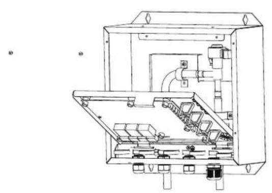
natural_image
Technical line drawing of an electrical enclosure with internal components and wiring (no text or symbols)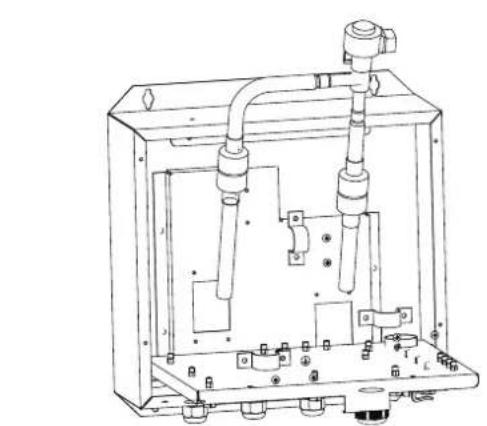
natural_image
Technical line drawing of a mechanical device with internal components and mounting base (no text or symbols)Imagen 3-3
Imagen 3-11
Imagen 3-12
natural_image
Pure electrical circuit lines without any symbolsImagen 3-13
Specifications are subject to change without notice.
Imagen 3-14
natural_image
Pure electrical circuit lines without any symbolsImagen 3-15
Nota:
Owner's and Installation Manual
HTW-AHUKZ01D | HTW-AHUKZ02D | HTW-AHUKZ03D
CONTENTS
1 PRECAUTIONS 01
2 INTRODUCTION 02
3 INSTALLATION
• 3.1 Before Installation 04
• 3.2 Choosing an Installation Site 05
• 3.3 Installation Methods and Size 05
• 3.4 Refrigerant Piping 07
• 3.5 Temperature Sensor Installation 10
• 3.6 Electrical Connection.... 11
4 FUNCTION SETTINGS
• 4.1 Capacity Settings 18
• 4.2 Setting the Master/Slave AHU Control Box 18
• 4.3 Address Settings of AHU Control Box 18
• 4.4 Selection of Control by Return Air Temperature or by Outlet Air Temperature …… 19
• 4.5 Selection of Controllers 20
5 DIP DEFINITION 23
6 ERROR CODE AND QUERY 26
1 PRECAUTIONS
Be sure to conform to local, national, and international laws and regulations.
Read "PRECAUTIONS" carefully before installation.
The following precautions include important safety items. Observe them and remember them at all times.
Keep this manual in a handy place for future reference.
Installation must be performed by authorized personnel, in accordance with NEC and CEC requirements.
The safety precautions listed here are divided into two categories. In both cases, important safety information which should be carefully read is provided.
CAUTION
Failure to observe a caution may result in injury or damage to the equipment.
After completing the installation, make sure that the unit operates properly during start-up. Please instruct the customer on how to operate the unit and keep it properly maintained. Also, inform customers that they should store this installation manual along with the owner's manual for future reference.
WARNING
Be sure that only trained and qualified service personnel are allowed to install, repair, or service the equipment.
Improper installation, repair, and maintenance may result in electric shock, short-circuiting, leaks, fire, or other damage to the equipment.
Install strictly according to these installation instructions.
If installation is defective, it will cause water leakage, electric shocks, and fire.
When installing the unit in a small room, take measures to keep the refrigerant concentration from exceeding allowable safety limits in the event of refrigerant leakage.
Contact the place of purchase for more information. Excessive refrigerant in a closed ambient can lead to oxygen deficiency.
Use the included accessories parts and specified parts for installation.
If not, the unit could fall, or water leakage, electrical shock, or fire could occur.
Install at a strong and firm location which is able to withstand the unit's weight.
If the installation location is not strong enough or installation is not properly completed, the set could fall and cause injury.
The appliance must be installed 2.5 m above the floor. The appliance must not be installed in a laundry room.
Before obtaining access to terminals, all supply circuits must be disconnected.
The appliance must be positioned so that the plug is accessible.
The enclosure of the appliance shall be marked with words or symbols, and indicate the direction of the fluid flow.
For electrical work, follow the local national wiring standards, regulations and these installation instructions. An independent circuit and single outlet must be used.
If electrical circuit capacity is insufficient or there is a defect in the electrical work, it will cause an electrical fire to occur.
Use the specified cable, connect it tightly, and clamp the cable so that no external force will act on the terminal.
Improper connection or fixing could lead to overheating or fire at the connection.
Wiring routing must be properly arranged so that the control board cover is properly secured.
If the control board cover is not properly secured, it could lead to overheating at the connection point of the terminal, fire, or electrical shock.
If the supply cord is damaged, it must be replaced by the manufacturer or its service agent or a similarly qualified person in order to avoid a hazard.
An all-pole disconnection switch with a contact separation of at least 3 mm should be connected in fixed wiring.
When carrying out piping connection, be careful to avoid air from entering the refrigeration cycle.
Otherwise, lower capacity, over-high pressure in the refrigeration cycle, explosion and injury could occur.
Do not modify the length of the power supply cord or use an extension cord, and do not share the single outlet with other electrical appliances.
Otherwise, fire or electrical shock may occur.
Carry out the specified installation work after taking into account strong winds, typhoons or earthquakes.
Improper installation may cause the equipment to fall and cause accidents.
If the refrigerant leaks during installation, ventilate the area immediately.
Toxic gas may be produced if the refrigerant comes into contact with fire.
After completing the installation, check that the refrigerant does not leak.
Toxic gas may be produced if the refrigerant leaks into the room and comes into contact with a source of flame, such as a fan heater, stove, or cooker.

CAUTION
Ground the air conditioner.
Do not connect the ground wire to gas or water pipes, lightning rods or a telephone ground wire. Incomplete grounding may result in electrical shock.
Be sure to install a ground leakage breaker.
Failure to install a ground leakage breaker may result in electrical shock.
Connect the ODU wires first, and then connect the AHU control box wires.
You are not allowed to connect the air conditioner to a power source (including wiring and piping) until the air conditioner installation is completed.
While following the instructions in this installation manual, install drain piping in order to ensure proper drainage and insulate the piping in order to prevent condensation from occurring.
Improper drain piping may result in water leakage and property damage.
Install the AHU control box and ODUs, power supply wiring, and connecting wires at least 1 m away from televisions or radios in order to prevent image interference or noise.
Depending on the radio waves, a distance of 1 m may not be sufficient enough to eliminate the noise.
The appliance is not intended for use by young children or infirm persons without supervision.
Young children should be supervised to ensure that they do not play with the appliance.
2 INTRODUCTION
The AHU control box can be connected to the heat pump/heat recovery ODU and the third party AHU. Every third party AHU can be connected to one AHU control box or to several AHU control boxes in a parallel connection (up to four). This manual describes how to install and operate an AHU control box.
Using an AHU control box, a unit can be controlled by either return air temperature or by outlet air temperature.
- When return air temperature control is selected, the connected AHU can be considered to be a standard IDU.
- Users can opt to use the factory controller or a third party controller
- The AHU control box has an input port of 0-10V. A third party controller is required to provide 0-10V of input. The system capacity requirement or temperature can be set based on 0-10V input. For details, refer to Section 5.2.2 Setting Capacity Output Mode via a Third Party Controller (Type 1) and Section 5.2.3 Setting Temperature Mode via a Third Party Controller (Type 2)
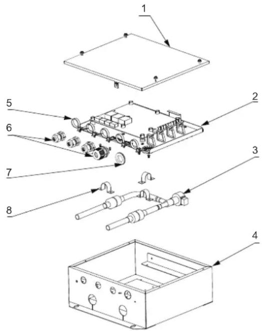
| NO. | Part and components |
| 1 | Electric control box cover assembly |
| 2 | E-part box assembly |
| 3 | Electronic expansion valve assembly |
| 4 | Electric control box welding assembly |
| 5 | Clip |
| 6 | Cable gland |
| 7 | Rubber ring |
| 8 | Fixing board,popes |
3 INSTALLATION
Accessories
| SHAPE USENAME | QUANTITY | ||
| Installation & owner's manual |  | 1 | —— |
| Wired controller |  | 1 | Wired controller |
| Electronic expansion valve adapter cable group | 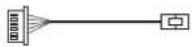 | 1 | —— |
| Fixed clamp of temperature sensor |  | 3 | —— |
| Sleeve |  | 3 | —— |
| Screw ST3.9x25 |  | 4 | Secure the installation board |
| Plastic expanded tube |  | 4 | —— |
| Temp.sensor | 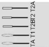 | 5 | —— |
| Temp.sensor connecting wire group |  | 5 | —— |
| Tie wrap | 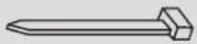 | 5 | —— |
Installation layout

Figure 3-1
Table 3-2 Names and functions
| No. | Name | Description |
| 1 | ODU | Outdoor units |
| 2 | AHU control box | - |
| 3 | Air handling unit (AHU) | Field supply |
| 4 | Liquid pipe | Field supply |
| 5 | Gas pipe | Field supply |
| 6 | Wired controller | Factory controller |
| 7 | Third party controller | Field supply |
| 8 | Temperature sensor wiring | - |
3.1 Before Installation
- An AHU control box can be connected to a heat pump ODU or a heat recovery ODU.
- When an AHU control box is connected to a heat recovery ODU, the system is not allowed to connect to AHU only. The IDU/ODU capacity ratio of common IDUs should be 50%-100%, that of the AHU control box should be 0%-50%, and that of the entire system should be 50%-100%.
- When a heat pump ODU is employed and the AHU control box is connected to AHU indoors: If no common IDUs are also connected, the IDU/ODU capacity ratio should be 50%-100%; if common IDUs are also connected, the IDU/ODU capacity ratio should be 50%-100%, that of the AHU control box should be 0%-50%, and that of the entire system should be 50%-100%.
- When a heat recovery ODU is employed and the AHU control box is connected to a FAPU, the unit can only be controlled by the outlet air temperature. The FAPU capacity of the entire system should not exceed 30% of the ODU capacity.
- When a heat pump ODU is employed and the AHU control box is connected to a FAPU, the unit can only be controlled by the outlet air temperature. If no common IDUs are connected, the IDU/ODU capacity ratio should be 50%-100%; if common IDUs are also connected, the FAPU capacity of the entire system should not exceed 30% of the ODU capacity.
When an AHU control box is connected to a mini VRF ODU, only return air temperature control can be selected (outlet air temperature control cannot be selected)
Selecting an AHU control box that matches AHU:
The following parameters and restrictions stipulated in Table 3-3 and Table 3-4 must be considered when selecting the AHU control box. Otherwise, it may adversely affect the ODU's service life, operating range, and reliability.
NOTE
If the total capacity of IDUs exceeds the rated capacity of the ODU, the cooling and heating performance may be reduced when IDUs are in operation.
Table 3-3
| Model | Setting Cooling Capacity (HP) | AHU Capacity (kW) | Internal volume of heat exchanger (dm3) | Reference Air Volume (m3/h) | Max. air Volume (m3/h) |
| AHUKZ -00D | 0.8 | 2.2-2.8 | 0.35~0.4 | 500 | 600 |
| 1 | 2.8~3.6 | 0.4~0.45 | 550 | 650 | |
| 1.2 | 3.6~4.5 | 0.45~0.55 | 600 | 750 | |
| 1.7 | 4.5~5.6 | 0.55~0.65 | 750 | 900 | |
| 2 | 5.6~7.1 | 0.65~0.75 | 850 | 1000 | |
| 2.5 | 7.1~8 | 0.75~1.2 | 1000 | 1300 | |
| 3 | 8~9 | 1.2~1.66 | 1300 | 1800 | |
| AHUKZ -01D | 3.2 | 9~11.2 | 1.66-2.06 | 1400 | 2400 |
| 4 | 11.2~14 | 2.06~2.58 | 1700 | 3000 | |
| 5 | 14~16 | 2.58~3.32 | 2100 | 3800 | |
| 6 | 16~20 | 3.32~3.69 | 2700 | 4300 | |
| AHUKZ -02D | 8 | 20~25 | 3.69~4.61 | 3000 | 5400 |
| 10 | 25~30 | 4.61~5.53 | 3700 | 6400 | |
| 12 | 30~36 | 5.53~6.64 | 4500 | 7700 | |
| AHUKZ -03D | 14 | 36~40 | 6.64~7.37 | 5400 | 8600 |
| 16 | 40~45 | 7.37~8.29 | 6000 | 9700 | |
| 20 | 45~56 | 8.29~9.21 | 7500 | 12000 |
Note: The evaporation temperature (cooling) is 6°C, the ambient temperature is 27°C DB/19°C WB, and the superheat degree is 5°C.
When the capacity of AHU exceeds 56 kW, up to four AHU control boxes can be connected in parallel to one AHU. See Table 3-4 for recommended parallel connection methods.
Table 3-4
| Recommended Parallel Combinations | AHU Capacity (kW) | Internal volume of heat exchanger (dm3) | Reference Air Volume (m3/h) | Max. air Volume (m3/h) |
| AHUKZ-02D+AHUKZ-02D | 56~65 | 9.63~11.56 | 8200 | 14000 |
| AHUKZ-02D+AHUKZ-03D | 65~70 | 11.03~12.54 | 9400 | 15100 |
| AHUKZ-02D+AHUKZ-03D | 70~76 | 11.90~13.30 | 10200 | 16400 |
| AHUKZ-02D+AHUKZ-03D | 76~80 | 12.62~14.01 | 10800 | 17200 |
| AHUKZ-02D+AHUKZ-03D | 80~90 | 13.40~15.26 | 11800 | 19400 |
| AHUKZ-03D+AHUKZ-03D | 90~100 | 15.26~17.80 | 13400 | 21600 |
| AHUKZ-03D+AHUKZ-03D | 100~112 | 17.51~19.61 | 15000 | 24100 |
| AHUKZ-02D+AHUKZ-02D+AHUKZ-03D | 112~125 | 18.85~21.36 | 16700 | 27000 |
| AHUKZ-02D+AHUKZ-03D+AHUKZ-03D | 125~140 | 21.19~24.07 | 18700 | 30200 |
| AHUKZ-03D+AHUKZ-03D+AHUKZ-03D | 140~155 | 23.74~26.62 | 21000 | 33400 |
| AHUKZ-02D+AHUKZ-02D+AHUKZ-03D+AHUKZ-03D | 155~175 | 26.20~29.36 | 23700 | 37800 |
| AHUKZ-02D+AHUKZ-03D+AHUKZ-03D+AHUKZ-03D | 175~198 | 29.02~32.84 | 26200 | 42700 |
| AHUKZ-03D+AHUKZ-03D+AHUKZ-03D+AHUKZ-03D | 198~225 | 33.17~37.15 | 30000 | 48600 |
Perform checks upon completion of installation, and pay extra attention to the following items:
• Whether the temperature sensor is properly installed.
• Whether AHU control boxes are properly secured.
• Whether electrical connections meet specifications.
• Whether wires and pipes are correctly connected.
• Whether AHU control boxes are properly grounded.
• Whether capacity DIP switches are properly set.
3.2 Choosing an Installation Site
The following conditions must be met:
If the AHU control box is installed outdoors, take waterproofing measures to protect it from rainwater.
Avoid direct sunlight, as it will heat the AHU control box and shorten its service life, hence affecting operation.
Select a level, solid-mounting surface.
Do not install the AHU control box on or above the surface of the ODU.
Reserve some space in front of the AHU control box for future maintenance.
Ambient temperature: -25^ to +52^
Inlet air temperature range on AHU coil (T1):
Cooling: 17^ C - 43^ C
Heating: 5^ - 30^
IP Protection Degree: IP20 (after proper installation)

CAUTION
Do not install or operate AHU control boxes in the following indoor environments:
- Places with fossil fuels (such as kitchens containing oil or natural gas)
- Places containing sulphuric gas, such as a hot spring
- Places exposed to strong electromagnetic fields
- Places with large voltage fluctuations
- Places where acidic or alkaline steam is present
- Places with high concentrations of vapour or spray
3.3 Installation Methods and Size
For installation of the field supply AHU, refer to the AHU installation manual.
The AHU control box can be installed in two ways:
- When the AHU control box's EEV remains with the AHU control box, the AHU control box must be installed vertically, as shown in Figure 3-2.
- When the AHU control box's EEV is split from the AHU control box, the AHU control box can be installed vertically or horizontally, but the split EEV must be vertical, as shown in Figure 3-2.
Units: mm
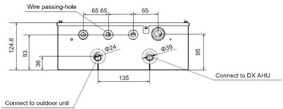

Figure 3-2
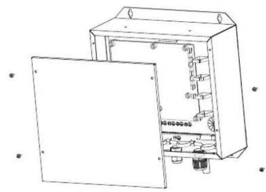
How to remove EEV from the AHU control box. The EEV may be removed from the AHU control box and positioned in an external location. Follow these steps to remove the EEV from the box.
natural_image
Technical line drawing of an open electrical enclosure with internal components (no text or symbols)
natural_image
Technical line drawing of an electrical enclosure with internal components and mounting brackets (no text or symbols)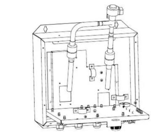
natural_image
Technical line drawing of a mechanical device with internal components and mounting holes (no text or symbols)Figure 3-3
3.4 Refrigerant Piping
3.4.1 Material and Size of the Piping
Only seamless phosphorus-deoxidized copper piping that complies with all applicable laws should be used. Temper grades and minimum thicknesses for different diameters of piping are specified in Table 3-5.
Table 3-5
| Piping Outer Diameter (mm) | Temper | Min. Thickness (mm) |
| Φ6.35 | O (annealed) | 0.8 |
| Φ9.53 | 0.8 | |
| Φ12.7 | 0.8 | |
| Φ15.9 | 1.0 | |
| Φ19.1 | 1.0 | |
| Φ22.2 | 1/2H (half hard) | 1.2 |
| Φ25.4 | 1.2 | |
| Φ28.6 | 1.3 | |
| Φ31.8 | 1.5 | |
| Φ38.1 | 1.5 | |
| Φ41.3 | 1.5 | |
| Φ44.5 | 1.5 | |
| Φ54.0 | 1.8 |
Note: O: coiled piping; 1/2H: straight piping.
When the required pipe sizes (in inch) are not available, other diameters (in mm) may also be used, provided that the following is taken into account:
- Select the pipe size nearest to the required size.
- Use suitable adapters for the change-over from inch to mm pipes (field supply).
3.4.2 Pipe Limits

Figure 3-4
- The connecting distance of each control box and AHU should not be more than 8 m. If the AHU control box and EEV are to be installed apart, the distance between them must be within 5 m.
- The maximum allowed piping length between the ODU and the AHU control box depends on the ODU model.
3.4.3 Welding Precautions
- Nitrogen must be applied before welding.
Failure to apply nitrogen in advance may result in a large amount of oxide residue on the interior surface of the copper tube, which will affect the normal operation of the valve body and compressor, and may damage the compressor in serious cases.
- When performing welding, use the pressure relief damper to keep the nitrogen pressure in the pipe at the range of 0.02-0.03 Mpa (as if the air is blowing gently on the skin).

Figure 3-5
| 1 | Refrigerant piping |
| 2 | Part to be brazed |
| 3 | Nitrogen connection |
| 4 | Hand-operated valve |
| 5 | Pressure relief damper |
| 6 | Nitrogen |
3.4.4 AHU Control Box Installation
- Drill four holes where you want to install the box, with the positions of the holes shown below. Secure the AHU control box using screws.

Figure 3-6
- Remove seals from the inlet and outlet.
- Weld pipes on site
flowchart
graph LR
    A["Outdoor Unit"] -->|L3| B["Liquid pipe"]
    B -->|a1| C["A"]
    C -->|L1| D["B"]
    D -->|b1| E["C1"]
    E --> F["Gas pipe"]
    F --> G["N2"]
    G --> H["b2"]
    H --> I["B"]
    I --> J["L2"]
    J --> K["A"]
    K --> L["L4"]
    L --> M["Liquid pipe"]
    N["DX AHU"] --> O["PH19.1."]
    P["AHUKZ-03D(56kW)"] --> Q["N0"]
    R["AHUKZ-02D(28W)"] --> S["N1"]
    T["AHUKZ-01D(14kW)"] --> U["N2"]
    V["φ19.1."] --> W["PH19.1."]

NOTE
When welding pipes at the AHU control box, the valve body and filter should be cooled with a wet cloth to prevent damage to the EEV due to excessively high temperatures.
- After the pipes are installed, insulate the pipes.
- Pipe diameter requirements for the AHU control box are as follows:
Table 3-6
| Control Box | AHUKZ-00D | AHUKZ-00D | AHUKZ-01D | AHUKZ-02D | AHUKZ-03D |
| Capacity A(×100W) | A<56 | 56≤A≤90 | 90200360 | 200360 | 360≤560 |
| Liquid Side (mm) | Φ6.35 | Φ9.53 | Φ9.53 | Φ12.7 | Φ15.9 |
For installation of other piping and branch pipes, refer to the ODU installation manual.
3.4.5 Pipe classification
Table 3-7
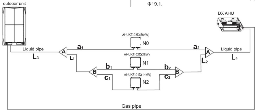
| Pipe name | Code(refer to Figure 3-7) |
| AHU Control box main pipe | L1, L2,L3, L4 |
| AHU Control box aux. pipe | a1,a2,b1,b2,c1,c2 |
| AHU Control box branch joint assembly | A, B |
Note:
The connecting distance of each control box and DX
AHU should not more than 8 m
a2+L4≤8m b2+L2+L4≤8m c2+L2+L4≤8m
3.4.6 Size of joint pipe for R410A DX AHU
Table 3-8
| Capacity of AHU control box A(×100W) | Size of main pipe(mm) | |
| Liquid side(mm) | Available branch joint | |
| 200< A≤450 | Φ12.7 | FQZHD-01 |
| 450< A<660 | Φ15.9 | FQZHD-02 |
| 660≤A<1350 | Φ19.1 | FQZHD-03 |
| 1350≤A<1800 | Φ22.2 | FQZHD-04 |
| 1800≤A | Φ25.4 | FQZHD-04 |
e.x.1: Refer to Figure 3-7, the capacity of downstream controller box to L4 is 560+280+140=980, the pipe is Φ19.1.
Figure 3-7
3.4.7 Example
Take (56+28+14)kW that composed by three control boxes as an example to clarify the pipe selection.
Table 3-9
| Controller box capacity A (×100W) | AHUKZ-01D 90≤A≤200 | AHUKZ-02D 200AHUKZ-03D 360 | AHUKZ-03D 360 |
| Liquid side(mm) | Φ9.53 | Φ12.7 | Φ15.9 |
A. The branch pipe at the controll box.
There are a\~c branch pipe at the control box, the branch pipe diameter should be select as Table. 3-6. The pipe a1/a2 diameter is 15.9 , the pipe b1/b2 diameter is 12.7 , the pipe c1/c2 diameter is 9.53 .
B. Main pipe at the control box (Refer to Table. 3-8)
1) The main pipe L1/L2 with N1, N2 downstream control box that total capacity is 280+140=420 , the pipe L1 diameter is 12.7 , thus select FQZHD-01 for the branch joint B.
2) The main pipe L3/L4 with N0 N1 N2 downstream control box that total capacity is 560+280+140=980, the pipe L3/L4 diameter is Φ19.1, that select FQZHD-03 for the branch joint A.
3) The branch joint A with N_0 N_2 downstream control box that total capacity is 560 + 280 + 140 = 980 thus select FQZHD-03 for the branch joint A.
Note:
1) The pipe L3 diameter is still related to outdoor unit, take the large one for your selection.
2) The gas pipe should be confirmed according to the outdoor unit installation manul.
3.4.8 Other piping methods for example.
Single VRF DX AHU Control Box connect to one AHU
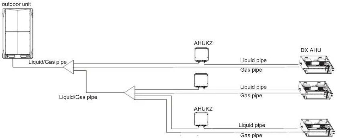
flowchart
graph LR
    A["Outdoor Unit"] -->|Liquid/Gas pipe| B["Hybrid"]
    B --> C["Hybrid"]
    C --> D["HXU"]
    C --> E["HXU"]
    style A fill:#f9f,stroke:#333
    style B fill:#ccf,stroke:#333
    style C fill:#cfc,stroke:#333
    style D fill:#fcc,stroke:#333
    style E fill:#cff,stroke:#333
Piping to heat recovery outdoor unit.

flowchart
graph TD
    A["outdoor unit"] --> B["MS"]
    B --> C["Liquid/Gas pipe"]
    B --> D["AHUKZ"]
    D --> E["Liquid pipe"]
    D --> F["Gas pipe"]
    B --> G["AHUKZ"]
    G --> H["Liquid pipe"]
    G --> I["Gas pipe"]
    B --> J["AHUKZ"]
    J --> K["Liquid pipe"]
    J --> L["Gas pipe"]
    B --> M["Liquid pipe"]
    M --> N["Gas pipe"]
    B --> O["DX AHU"]
Note: The maximum capacity of every AHU connected to MS box should not be exceed 28Kw.
3.5 Temperature Sensor Installation
There are five temperature sensors (T1, TA, T2A, T2, and T2B) and five extension wires in the accessories, as shown in Figure 3-8.
Temperature sensor Extension wire


natural_image
Two black cable connectors with white connectors and copper wires attached, placed on a green surface (no text or symbols visible)Figure 3-8
Mounting location for temperature sensors:
T1 is an AHU inlet air temperature sensor; it should be installed at the air inlet of the AHU.
T2A is an AHU evaporator inlet temperature sensor; it should be installed at the inlet pipe of the evaporator.
T2 is an AHU evaporator intermediate temperature sensor; it should be installed at the intermediate pipe of the evaporator.
T2B is an AHU evaporator outlet sensor; it should be installed at the outlet pipe of the evaporator.
TA is an outlet air temperature sensor and therefore does not need to be installed if outlet air temperature control is not selected.
Mounting location of T2A, T2, and T2B tube temperature sensors

Figure 3-9
Installation of tube temperature sensors T2A, T2 and T2B
- Weld the sleeves of the temperature sensors at the designated mounting location.

Figure 3-10
- Insert the temperature sensor into the sleeve after inserting the buckle.
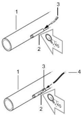
Figure 3-11
- Apply insulation materials and secure with cable ties.

Figure 3-12
Mounting location of indoor temperature sensors T1 and TA


natural_image
Pure technical line drawings of U-shaped pipe fittings without any text, numbers, or symbolsFigure 3-13
Using an extension cord with the temperature sensor to allow long distance connection
The attached extension cord of the temperature sensor is 9 m long. If an extension cord is required, connect one end of the cord to the AHU control box and the other end to temperature sensor mounted on the AHU.
3.6 Electrical Connection
CAUTION
- The ODU and AHU control box should use separate power supplies with rated voltage. However, the AHU control box and other AHUs in the same system should use the same power.
- The external power supply to the air conditioner should have ground wiring, which is linked to the ground wiring of the AHU control box and ODU.
- The wiring work should be completed by qualified persons according to circuit drawing.
- The fixed connecting lines must be equipped with at least 3 mm of electric shock spacing.
- A leakage protector should be installed in accordance with the local electrical standard.
- Be sure to properly locate the power wiring and the signal wirings to avoid causing cross-disturbance and their contact with the connecting pipe or stop value body. Generally, do not twist two wirings together unless the joint is well-soldered and covered with insulator tape.
- Do not turn on the power until the electrical wiring have been correctly completed.
3.6.1 Circuit Diagram
Please refer to the circuit diagram for wiring.
Circuit diagram

flowchart
graph TD
    subgraph Main Board
        CN31["CN31"] -->|ENC1 ENC2 ENC3 ENC4| SW1["SW1"]
        CN33["CN33"] -->|POWER LOW MIDDLE HIGH| SW2["SW2"]
        CN30["CN30"] -->|M-smart| CN25["CN25"]
        CN2["CN2"] --> L["L"]
        CN2 --> N["N"]
        CN2 --> NHIGH["HIGH"]
        CN2 --> LOW["MIDDLE[LOW"]]
        CN2 --> L'N' [L']
        CN2 --> AUX["AUX"]
        CN2 --> COM["COM"]
        CN2 --> Alarm["Alarm Defrost"]
        CN2 --> Run["Run"]
        CN2 --> DisplayBoard["Display board"]
        CN2 --> XP12["XP12"]
        CN2 --> XP11["XP11"]
        CN2 --> EEV["EEV"]
        CN2 --> Switch["CN31-ON/CN35 ON/OFF/COOL/HEAT/FAN COM 0-10V output 0-10V input"]
        CN2 --> Switch --> Water["ON/OFF switch"]
        CN2 --> Switch --> Third-party["Third party controller"]
        CN2 --> Switch --> MagnetRing["Magnet ring"]
        CN2 --> Switch --> Factory["To wired controller (factory)"]
        CN2 --> Switch --> AHUControlBox["To master/slave AHU control box comm.bus"]
        CN2 --> Switch --> WaterLevelSwitch["Water level switch if the drain-age pump is available"]
    end

    subgraph Single-phase AC motor
        CN31 -->|P Q E| ToOutdoorMSUnit["To Outdoor/MS units comm.bus"]
        CN33 -->|D1 D2 E| ToWiredController["To wired controller (optional)"]
        CN30 -->|X1 X2| ToMasterSlaveAHU
        CN26 -->|ON/OFF switch| Water
        CN25 -->|ON/OFF switch| Water
        CN24 -->|ON/OFF switch| Water
        CN23 -->|ON/OFF switch| Water
        CN22 -->|ON/OFF switch| Water
        CN21 -->|ON/OFF switch| Water
        CN15 -->|T2B T1 T2A TA| RedRed["RED XS1 XP1 XS2 XP2 WHITE XS3 XP3 XS4 XP4 BLACK XS5 XP5 XS6 XP6 BLUE XS7 XP7 XS8 XP8 YELLOW XS9 XP9 XS10 XP10 TA"]
    end

    style Main Board fill:#f9f,stroke:#333
    style Single-phase AC motor fill:#ccf,stroke:#333
    style Main Board fill:#cfc,stroke:#333
    style Single-phase AC motor fill:#fcc,stroke:#333
    style Main Board fill:#ffc,stroke:#333
    style Single-phase AC motor fill:#cff,stroke:#333
Figure 3-14Specifications are subject to chang
3.6.2 Wiring Inside the Electric Control Box
For connections to the AHU control box : Pull the wires inside through the screw nut and fasten the nut firmly to ensure a good pull relief and water protection.
The cables require an additional pull relief. Strap the cable with the installed tie wrap.

natural_image
Technical diagram of a mechanical assembly with no visible text or symbolsFigure 3-15
Note:
The connection with the terminal block must be secure. Failure to do so may result in heating due to poor contact, and even fire in serious cases.
The power cable and the communication cable should be separated by at least 50 mm to prevent electromagnetic interference.
Connect the cables to the main board in accordance with the circuit diagram shown in Figure 3-14.
Connect cables in accordance with the following table.
Table 3-10
| Description Connected To | Cross Section (mm2) | Max. Length (m) | Specification | ||
| L, N | Power supply | Power supply | * | - | 220-240V 1Ph50/60hz |
| LOW/MIDDLE/HIGH, N | Fan speed signal | AHU fan | # | - | 220-240V 1Ph50/60hz |
| EEV | Electronic expansion valve | Electronic expansion valve | - | 5 | 0-12VDC |
| T1 | Inlet air temperature | AHU | 10 | 0-5VDC | |
| TA | Outlet air temperature | AHU heat exchanger | 10 | 0-5VDC | |
| T2A | Heat exchanger inlet temperature | AHU heat exchanger | 10 | 0-5VDC | |
| T2 | Heat exchanger intermediate temperature | AHU heat exchanger | 10 | 0-5VDC | |
| T2B | Heat exchanger outlet temperature | AHU | 10 | 0-5VDC | |
| P, Q, E | Communication cable connected to ODU/MS | ODU / MS | 0.75 | 1200 | 0-5VDC |
| X1, X2 | Wired controller | Factory controller | 200 | 18VDC | |
| D1, D2, E | Wired controller (optional) | Factory controller | 1200 | 0-5VDC | |
| C1, C2, E | Comunicate with AHU control box | Master/slave AHU control box | 1200 | 0-5VDC | |
| ON/OFF | Remote on/off | Third party controller | 0-12VDC | ||
| cool | Cooling signal | Third party controller | 0-12VDC | ||
| heat | Heating signal | Third party controller | ** | 0-12VDC | |
| fan | Fan status | Third party controller | 0-12VDC | ||
| alarm | Alarm signal | Third party controller | 0-24VDC/AC | ||
| defrost | Defrosting/anti-cold wind signal | Third party controller | 0-24VDC/AC | ||
| run | Operating Status | Third party controller | 0-24VDC/AC | ||
| AUX | Electric auxiliary heater signal | Electric auxiliary heater | 0-12VDC |
*Refer to Cross section of main power cable
Refer to Fan wiring
**The maximum length depends on the external device that is connected (controller, relay ...).
3.6.3 Temperature Sensor Wiring 3.6.4 Cross section of main power cable
The temperature sensors come with two wiring methods, by dialling DIP switch SW9-2.
| Type | SW9 | |
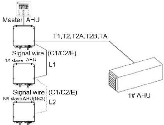
| 1 |  | SW9-2 is 0: One or more AHU control boxes are connected in parallel to one AHU; one coil is connected to multiple control boxes; (shielding faults from slave unit's temperature sensors T1, T2, T2A, TA and T2B) (factory default) |
 | ||
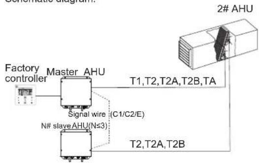
| 2 |  | SW9-2 is 1: Multiple AHU control boxes are connected in parallel. In the event of multiple coils, one coil is connected to one control box; (shielding faults from slave unit's temperature sensor T1, TA) |
| 1 2 3 SW9 |
Type 1: One or more AHU control boxes are connected in parallel to one AHU, and the T2A, T2 and T2B sensors of any coil of AHU are connected to the master AHU control box. The T1 and TA sensor is connected to the main board of the master AHU control box.
Schematic diagram:
flowchart
graph TD
    A["Master AHU"] --> B["Signal wire (C1/C2/E)"]
    A --> C["Signal wire (C1/C2/E)"]
    A --> D["Signal wire (C1/C2/E)"]
    B --> E["L1"]
    C --> F["L2"]
    D --> G["N# slave AHU(Ns3)"]
Figure 3-16
Type 2: Multiple AHU control boxes are connected in parallel. Each coil is connected to an AHU control box. The T2A, T2 and T2B sensors of each coil are connected to the main board of the corresponding AHU control box. The T1 and TA sensor only needs to be connected to the master AHU control box.
Schematic diagram:
flowchart
graph TD
    A["Factory controller"] --> B["Master AHU"]
    B --> C["Signal wire (C1/C2/E)"]
    B --> D["N# slave AHU(N≤3)"]
    E["2# AHU"] --> F["T1,T2,T2A,T2B,TA"]
    E --> G["T2,T2A,T2B"]
    style A fill:#f9f,stroke:#333
    style E fill:#ccf,stroke:#333
Figure 3-17
Please select the main power cable. Refer to Table 3-11 and Table 3-12.
Table 3-11
| AHUKZ-00D~01DModel | ||
| Power | Phase | Single-phase |
| Voltage and Frequency | 220-240V - 50/60Hz | |
| AHU Control Box Power Wire (mm ^2 ) | 2.0 (<50 m) | |
Table 3-12
| AHUKZ-02D~03DModel | ||
| Power | Phase | Single-phase |
| Voltage and Frequency | 220-240V - 50/60Hz | |
| AHU Control Box Power Wire (mm2) | 4.0 (<50 m) | |
CAUTION
- Specific wiring requirements must adhere to local wiring regulations.
- Use only copper wires.
- Be sure to use specified wires for connections and ensure that no external force is imparted to terminal connections. If connections are not firmly secured, overheating or fires may result.
- The wire size is the minimum value for metal conduit wiring. If the voltage drops, use a wire that is one rank thicker in diameter. Make sure the power-supply voltage does not drop by more than 10%.
- Power must be unified supply to all AHU control boxes in the same system.
- A breaker for current leakage must be attached to the power supply. If no ground leakage breaker is installed, it may cause electrical shock.
- Never connect the main power source to a terminal block of the communication line. If connected, electrical parts will burn out.
3.6.5 Fan Wiring
Fan signal:
The AHU control box has two output modes to control fan speed: an analog signal output LOW/MIDDLE/HIGH and an output of 0-10V, respectively. The output mode is selected based on the actual on-site needs of the AHU.
Table 3-13
| Fan Signal | LOW/ MIDDLE/HIGH | 0-10V output |
| Low | LOW | # |
| Middle | MIDDLE | # |
| High | HIGH | # |
: Refer to 0-10V output control
0-10V Output control
The DIP switch numbers of ENC2, ENC3 and ENC4 correspond to different voltage outputs. Depending on the DIP switch numbers of SW1-2, there are two control modes available, which are gear 1 and gear 3 fan speeds, respectively.
- SW1-2 dialled to "OFF" (factory default)
ENC2, ENC3 and ENC4 are respectively defined as low, middle and high voltage output signals. By default, ENC2 is set to 2V, ENC3 is set to 7V, and ENC4 is set to A (A is 10V). See the table below for their corresponding relations:
Table 3-14
0-10V output Voltage
 (2V Factory Default) (2V Factory Default) |  (7V Factory Default) (7V Factory Default) |  (10V Factory Default) (10V Factory Default) | ||||||||||||||
| Fan output voltage of Low speed Fan | output voltage of Middle speed Fan output voltage of High speed | |||||||||||||||
| Dial code 0 | 1 | 2 | 3 | 4 | 5 | 6 | 7 | 8 | 9 | A | B | C | D | E | F | |
| Voltage(V) | 1 | 1 | 2 | 3 | 4 | 5 | 6 | 7 | 8 | 9 | 10 | 10 | 10 | 10 | 10 | 10 |
Note: ENC2<ENC3<ENC4. If not satisfied, fault H9 is reported.
2. SW1-2 dialled to "ON"
This indicates that the fan has only one fan speed. In this case, ENC2 indicates the fan speed while ENC3 indicates a 0-10V output voltage for the corresponding gear. ENC4 is not defined.
Table 3-15
| ENC2 DIP | Fan Speed | LOW/MIDDLE/HIGH | 0-10V output |
| 0 | Low only | LOW output | ENC3 voltage |
| 1 | Middle only | MIDDLE output | ENC3 voltage |
| 2 (by default) | High only | HIGH output | ENC3 voltage |
| 3-F | High only | HIGH output | ENC3 voltage |
Corresponding voltage for the ENC3 DIP switch:
Table 3-16
| Dial code 0 | 1 | 2 | 3 | 4 | 5 | 6 | 7 | 8 | 9 | A | B | C | D | E | F | |
| Voltage(V) | 1 | 1 | 2 | 3 | 4 | 5 | 6 | 7 | 8 | 9 | 10 | 10 | 10 | 10 | 10 | 10 |
Wiring between the terminal block and fan
The sum current of the drainage pump and fan motor should not be greater than 3.5A in models AHUKZ-00D and AHUKZ-01D. The sum current of the drainage pump and fan motor should not be greater than 15A in models AHUKZ-02D and AHUKZ-03D.
The unit should be equipped with molded case circuit breaker, refer to Table 3-17.
The AHU control box has a control port for single-phase AC motor; refer to Figure 3-18 and Figure 3-19. It has three different speeds (high, medium, and low), the output voltage will also be the same as the input power of the box. Figure 3-18 and Figure 3-19 show the wiring diagram. Figure 3-18 is the recommended wiring in these two ways. In Figure 3-18, the AHU control box is not directly connected to the fan motor. Always use it as a motor driving the relay contacts. Otherwise, the product could be damaged or a fire could occur.


If wiring as shown in Figure 3-19, the maximum current of the fan motor must not exceed the value shown in Table 3-17. Table 3-17
| Model | Max. Current of AC Motor and Drainage pump | Molded case circuit breaker |
| AHUKZ-00D~01D | 3.5A | 6A |
| AHUKZ-02D~03D | 15A | 20A |
If the fan motor is a 3-Phase AC motor, SW1-2 must be set to "ON", and the ENC2 must be dialled to "2". The fan terminal block only supports high-speed output. When wiring the motor, refer to Figure 3-20.
| SW1, ENC2 | ||
ON |  | Only high-speed is available |
Note:
- The rated current of the contactor must be greater than the current of the motor.
- The control power of the contactor must be the same as the input power of the AHU control box.
- SW1-2 must be set to "ON".
- ENC2 must be dialled to "2".
- The product do not include the breaker and contactor.

Figure 3-20
3.6 Signal Cable Connection
The following figure displays the signal cable connection diagram:

flowchart
graph TD
    CN10["CN10"] -->|P Q E| CN19["CN19"]
    CN19 -->|D1 D2 E| CN5["CN5"]
    CN5 -->|C1 C2 E| CN23["CN23"]
    CN23 -->|X1 X2| CN8["WATER"]
    CN8 -->|Magnet ring| CN10
    CN10 -->|P Q E| ToOutdoor["To Outdoor/MS units comm.bus"]
    CN19 -->|D1 D2 E| ToWired["To Wired Controller (optional)"]
    CN5 -->|C1 C2 E| ToMaster["AHU control box comm.bus"]
    CN23 -->|X1 X2| ToWired
    CN8 -->|Water level switch| WaterLevelSwitch["Water level switch to the water level switch if the drainage pump is available"]
Figure 3-21
Note:
The connecting terminals of the water level switch are connected by default. When connecting the AHU with the drainage pump, remove the connecting wire and connect to the water level switch.
X1 and X2 are ports for connecting to a standard wired controller, while D1,D2 and E are ports for connecting to the optional wired controller. For specific models, consult the manufacturer's technical support personnel or a local dealer.
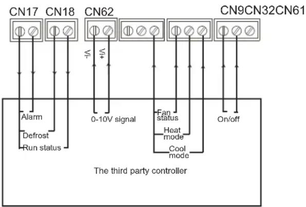
When a third party controller is used, communication between the AHU control box and third party controller is achieved via dry contacts. See the signal cable connection diagram below:
flowchart
graph TD
    A["CN17"] --> B["Alarm"]
    A --> C["Defrost"]
    A --> D["Run status"]
    E["CN18"] --> F["0-10V signal"]
    G["CN62"] --> H["Fan status"]
    G --> I["Heat mode"]
    G --> J["Cool mode"]
    K["CN9CN32CN61"] --> L["On/off"]
    style A fill:#f9f,stroke:#333
    style E fill:#f9f,stroke:#333
    style K fill:#f9f,stroke:#333
    style B fill:#ccf,stroke:#333
    style F fill:#ccf,stroke:#333
    style H fill:#ccf,stroke:#333
    style I fill:#ccf,stroke:#333
    style J fill:#ccf,stroke:#333
Figure 3-22
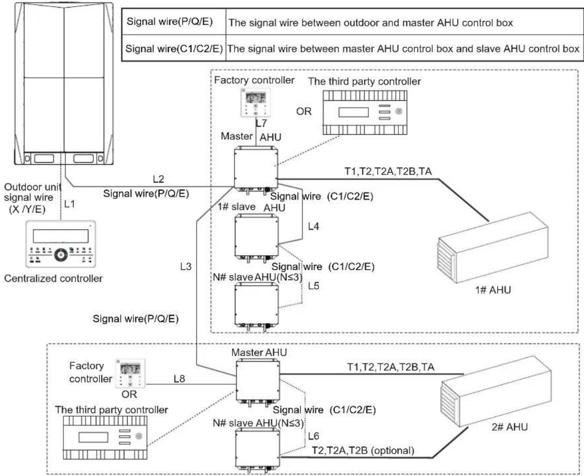
Example of signal wiring(Heat pump)
flowchart
graph TD
    A["Signal wire(P/Q/E)"] --> B["The signal wire between outdoor and master AHU control box"]
    C["Signal wire(C1/C2/E)"] --> D["The signal wire between master AHU control box and slave AHU control box"]
    E["Centralized controller"] --> F["L1"]
    F --> G["L2"]
    G --> H["L3"]
    H --> I["L4"]
    I --> J["L5"]
    J --> K["T1,T2,T2A,T2B,TA"]
    K --> L["Factory controller"]
    K --> M["The third party controller"]
    N["Signal wire(P/Q/E)"] --> O["L7"]
    O --> P["Master AHU"]
    Q["Signal wire(C1/C2/E)"] --> R["L4"]
    R --> S["Signal wire (C1/C2/E)"]
    T["N# slave AHU(N≤3)"] --> U["L5"]
    U --> V["1# AHU"]
    W["The third party controller"] --> X["L8"]
    X --> Y["Master AHU"]
    Z["2# AHU"] --> AA["L6"]
    AA --> AB["T2,T2A,T2B (optional)"]
    AC["Factory controller"] --> AD["OR"]
    AE["The third party controller"] --> AF["L8"]
Figure 3-23

flowchart
graph TD
    A["Outdoor unit signal wire (X/Y/E)"] -->|L1| B["Signal wire(P/Q/E)"]
    B -->|L9| C["MS BOX"]
    C -->|L10| D["Signal wire (P/Q/E)"]
    D --> E["T1,T2,T2A,T2B,TA"]
    E --> F["The third party controller"]
    F --> G["OR"]
    G --> H["1# AHU"]
    D --> I["L7"]
    I --> J["MS BOX"]
    J --> K["Signal wire(P/Q/E)"]
    K --> L["L11"]
    L --> M["MS BOX"]
    M --> N["L7"]
    N --> O["The third party controller"]
    O --> P["OR"]
    P --> Q["2# AHU"]
    O --> R["T1,T2,T2A,T2B,TA"]
Figure 3-24
Note:
1. The diameter of the signal wire should be greater than or equal to 0.75 mm², and the C1C2E and PQE signal wire should be 3-core shielding wire.
2. Maximum wiring length: L1<1200m; L2+L3<1200m; L4+L5<1200m; L6<1200m; L7<200m; L8<200m; L9,L10,L11<1200m;
3. If the third party controller is selected to control the AHU box, the centralized controller cannot be connected to the system. The system can only connect to the centralized controller if a factory controller is selected to control the AHU control box.
4. Connect the centralized controller to the ODU XYE terminal block. Do not connect the centralized controller to the C1C2E terminal block of the AHU control box.
4 FUNCTION SETTINGS
4.1 Capacity Settings
The capacity DIP switches for the AHU control box should be set after the box is installed.
The capacity can be set through ENC1 and SW4-2. After completing the settings, power off and then power on the unit to apply the settings.
NOTE
Each AHU control box in parallel connection should undergo capacity settings.
Table 4-1 Capacities of SW4-2 and ENC1
 | ENC1 | Capacity (hp) | Capacity (KW) | |
| 0 | 0 | 0.8 hp | 2.2 | AHUKZ-00D |
| 1 | 1.0 hp | 2.8 | ||
| 2 | 1.2 hp | 3.6 | ||
| 3 | 1.7 hp | 4.5 | ||
| 4 | 2.0 hp | 5.6 | ||
| 5 | 2.5 hp | 7.1 | ||
| 6 | 3.0 hp | 8.0 | ||
| 7 | 3.2 hp | 9.0 | AHUKZ-01D | |
| 8 | 3.6 hp | 10.0 | ||
| 9 | 4.0 hp | 11.2 | ||
| A | 4.5 hp | 12.0 | ||
| B | 5.0 hp | 14.0 | ||
| C | 6.0 hp | 16.0 | ||
| D | 6.5hp | 18.0 | ||
| E | 7.0hp | 20.0 | AHUKZ-02D | |
| F | 8.0 hp | 22.4 | ||
| 1 | 0 | 10.0 hp | 28.0 | |
| 1 | 12.0 hp | 33.5 | ||
| 2 | 14.0 hp | 40.0 | AHUKZ-03D | |
| 3 | 16.0 hp | 45.0 | ||
| 4 | 20.0 hp | 56.0 |
4.2 Setting the Master/Slave AHU Control Box
- If multiple AHU control boxes are connected in parallel, the master/slave AHU control box needs to be set through SW2-3 and SW2-4
 | SW2-3 and SW2-4 are 00: master AHU control box(factory default) |
 | SW2-3 and SW2-4 are 01: slave AHU control box 1 |
... | SW2-3 and SW2-4 are 10: slaveAHU control box 2 |
 | SW2-3 and SW2-4 are 11: slaveAHU control box 3 |
- When AHU control boxes are connected in parallel, the number of slave AHU control boxes must be set via SW1-3 and SW1-4.
Note: The number of slave AHU control boxes connected in parallel can only be set from the main board of the master AHU control box.
| [W5AS]Valid for the master unit only | SW1-3 and SW1-4 are 00: the number of slave AHU control boxes connected in parallel is 0 (factory default) |
 Valid for the master unit only Valid for the master unit only | SW1-3 and SW1-4 are 01: the number of slave AHU control boxes connected in parallel is 1 |
 Valid for the master unit only Valid for the master unit only | SW1-3 and SW1-4 are 10: the number of slave AHU control boxes connected in parallel is 2 |
 Valid for the master unit only Valid for the master unit only | SW1-3 and SW1-4 are 11: the number of slave AHU control boxes connected in parallel is 3 |
4.3 Address Settings of AHU Control Box
When powering-on for the first time, If the address is not set, the wired controller will display fault E9.
The ODU can use auto-addressing to set the address for an AHU control box which does not have an address.
If using manual setting, a wired controller is required to set the address of the AHU control box.
Only the master AHU control box communicates with the ODU. Therefore, only the address of master AHU control box needs to be set via the wired controller.
Press and hold ▲ and ▼ on the wired controller for 8s to enter the Address Settings page. If the AHU control box has an address, the page displays the current address. Otherwise, press ▲ and ▼ to change the address and press Ⓐ to confirm and send the current address to the AHU control box.

Figure 4-1
Note:
The address of the same system cannot be repeated.
When the AHU control box is set to have a capacity of over 18 kW and the capacity DIP switch is greater than D, a virtual address will be generated. The virtual address is equivalent to the actual address and occupies the address bit. When setting the address, do not set the actual address to a virtual address that is already occupied.
The master AHU control box calculates the total number of addresses occupied by AHU control boxes (represented by the letter N) based on the capacity of each AHU control box, and generates N-1 virtual addresses based on the set addresses.
Table 4-2
| ENC1SW4-2Corresponding Virtual Addresses | Qty of Occupied Addresses | ||||||
| 0 | 0~D | No virtual address | 1 | ||||
| 0 | E-F | Actual address +1 | / | / | / | / | 2 |
| 1 | 0-1 | Actual address +1 | / | / | / | / | 2 |
| 1 | 2-4 | Actual address +1 | Actual address +2 | Actual address +3 | / | / | 4 |
4.3.1 Single AHU Control Box Controlling One AHU
- If the ODU is V5X, the address quantity of the AHU control box detected by the ODU will be the sum of the actual address quantity and the virtual address quantity. For example, if the capacity code of an AHU control box is E, and the actual setting address is 5, a virtual address 6 will be generated based on Table 4-2, and the quantity of IDUs detected by the ODU will be 2. If the ODU is not a V5X ODU, the address quantity of the AHU control box detected by the ODU will be the sum of the actual address quantity.
- When the AHU control box system connects to the centralized controller, the actual address and the virtual address will be displayed for V5X ODUs. For example, if the capacity code of an AHU control box is E, and the actual setting address is 5, both the actual address 5 and the virtual address 6 will be displayed on the centralized controller. If the ODU is not a V5X ODU, only the actual address will be displayed.
- The network address is the same as the AHU control box address, so there is no need to set them separately.
- Each individual AHU control box controls one AHU. Each individual AHU control box is the main AHU control box.
4.3.2 Several AHU Control Boxes in a Parallel Connection Controlling One AHU
For this product, several AHU control boxes are allowed to connect in parallel to control one AHU. In this case, three steps must be completed.
- Set the master AHU control box, slave 1 AHU control box, slave 2 AHU control box, and slave 3 AHU control box by using SW2-3 and SW2-4.
- Set the quantity of slave AHU control boxes by using SW1-3 and SW1-4 on the master AHU control box.
- Set an address on the master AHU control box by a wired controller. This address is an actual address. Virtual addresses will be generated in the parallel connection system.
If there are several parallel AHU control boxes systems in one refrigerant system, take figure 3-23 for example, calculate the number of occupied virtual addresses for each parallel AHU control box system, and set the actual address of each parallel AHU control box system to avoid repetition of actual addresses and virtual addresses.
4.4 Selection of Control by Return Air Temperature or by Outlet Air Temperature
AHU control box can select the control by either return air temperature or by outlet air temperature via SW4-1.
 Valid for the master unit only Valid for the master unit only | SW4-1 is 0: return air temperature control (factory default) |
 Valid for the master unit only Valid for the master unit only | SW4-1 is 1: outlet air temperature control |
When return air temperature control is selected, a inlet air temperature sensor must be connected to AHU control box;
when outlet air temperature control is selected, both the return air temperature sensor and outlet air temperature sensor must be connected to AHU control box.
When outlet air temperature control is selected, AHU control box must use T1 coming from AHU instead of wired controller. At this time, wired controller should turn off the function of "Follow Me". Please refer to wired controller manual for more information.
4.5 Selection of Controllers
The factory controller or a third party controller can be selected for the AHU control box. The type of controllers can be selected through SW4-3 and SW4-4.
SW4-3, SW4-4
 | SW4-3 and SW4-4 are 00: factory controller mode (factory default) |
 | SW4-3 and SW4-4 are 01: capacity output mode of a third party controller |
| [G4BX] | SW4-3 and SW4-4 are 10: set temperature control mode of third party controller |
Note:
After DIP switches on main board are set, remember to power off and then power on the main board to apply the settings. Otherwise, the settings will be invalid.
When a third party controller is used, two control modes are available: capacity output control mode and set temperature control mode.
4.5.1 Factory Controller
When the factory controller is selected, the AHU control box can be controlled by the factory wired controller.
The factory wired controller in the accessories is connected to X1 and X2 ports on the main board.
Only the master AHU control box communicates with the ODU. As a result, when AHU control boxes are connected in parallel, only the factory wired controller of master AHU control box can communicate with ODU.

Factory wired controller
Figure 4-2
For detailed instructions for the wired controller, refer to the wired controller installation & owner's manual.
Note:
When the factory controller mode is applied, the main board of the AHU control box will not respond to the control signal from a third party controller.
4.5.2 Setting Capacity Output Mode via a Third Party Controller (Type 1)
When capacity setting with a third party controller mode has been selected, only the third party controller can be used to control the AHU control box. The signal from the factory controller will not respond except to the address setting and inquiring signal.
Even if capacity setting with third party controller mode has been selected, a factory remote controller or wired controller is needed to set the address for the AHU control box, because the third party controller does not have this function.
Third party controller wiring
For the wiring figure, refer to Figure 4-3. Pay careful attention to the following three things:
- The distance between the third party controller and the AHU control box depends on the external device that is connected (controller/relay...)
- If several AHU control boxes in a parallel connection control one AHU, the third party controller only needs to be connected with the master AHU control box.
- One third party controller cannot control two or more AHU at the same time.
Terminal block of AHU control box

flowchart
graph TD
    A["CN17"] --> B["Alarm"]
    C["CN18"] --> D["Defrost Run status"]
    E["CN62"] --> F["V-"]
    G["Fan status"] --> H["Heat mode"]
    I["On/off"] --> J["Cool mode"]
    K["The third party controller"] --> L["On/off"]
    M["0-10V signal"] --> N["V+"]
Figure 4-3
The definition of signals between the third party controller and AHU control box.
- Signals from the third party controller to the AHU control box.
Table 4-3
| Signal | Signal Type | Specification Port | |
| Capacity set | Analog voltage | 0-10VDC | 0-10V input |
| ON/OFF | Dry contact | Close: ON Disconnect: OFF | |
| Cool mode | Dry contact | Close: cool mode Disconnect: no cool signal | COOL |
| Heat mode | Dry contact | Close: heat mode Disconnect: no heat signal | HEAT |
| Fan status | Dry contact | Close: fan ON Disconnect: fan OFF | FAN |
Note:
(1) The analog voltage must be between the maximum and the minimum value.
(2) Don't close the heat mode contact and cool mode contact at the same time if it needs to run the AHU control box.
- Signals from the AHU control box to the third party controller.
Table 4-4
| Signal | Signal Type | Specification Port | |
| Alarm | Dry contact | Close: alarmDisconnect: no alarm | Alarm |
| Defrost | Dry contact | Close: defrostingDisconnect: no defrost | |
| Run status | Dry contact | Close: runningDisconnect: off | Run |
Note:
All signals between the third party controller and AHU control box must be in accordance with the definition specified in Table 4-3 and Table 4-4. It will not work correctly if the definition of the signal in the third party controller is not correct.
Operation at 0-10V capacity output
This control mode requires a third party controller equipped with a temperature sensor that is used to control the following temperatures:
- Return air temperature of the AHU
- Outlet air temperature of the AHU
The AHU control box will interpret the 0–10 V signal according to 10 steps. The correlation between the voltage output and the system capacity is shown in the table below.
Capacity setting requirement table(same in heating and cooling)
| Analog input 0-10V DC | Capacity setting requiment | |
| Normal (V) | Range (V) | |
| 0 | U<0.5 | 0% |
| 1 | 0.5≤U<1.5 | 10% |
| 2 | 1.5≤U<2.5 | 20% |
| 3 | 2.5≤U<3.5 | 30% |
| 4 | 3.5≤U<4.5 | 40% |
| 5 | 4.5≤U<5.5 | 50% |
| 6 | 5.5≤U<6.5 | 60% |
| 7 | 6.5≤U<7.5 | 70% |
| 8 | 8.5≤U<9.5 | 80% |
| 9 | 8.5≤U<9.5 | 90% |
| 10 | 9.5≤U≤10 | 100% |
Operation instruction
When the third party controller has been selected, AHU control box will operate according to the control signal from the third party controller and output alarm, defrost and run status signal.
4.5.3 Setting Temperature Mode via a Third Party Controller (Type 2)
When setting temperature control mode via third party controller has been selected, the AHU control box does not respond to instructions from the factory controller except for address setting and query.
Even if temperature control by a third party controller is applied, a factory controller is still needed to set the address because the third party controller cannot do so Third party controller wiring
Please refer to Figure 4-4 for the wiring diagram. Pay careful attention to the following three things:
- The distance between the third party controller and the AHU control box depends on the external device that is connected (controller/relay...)
- If several AHU control boxes in parallel connection control one AHU, the third party controller only needs to be connected with the master AHU control box.
Terminal block of AHU control box

flowchart
graph TD
    A["CN17"] --> B["Alarm"]
    C["CN18"] --> D["Defrost"]
    C --> E["Run status"]
    F["CN62"] --> G["Vc"]
    H["CN9CN32CN61"] --> I["Fan status"]
    H --> J["Heat mode"]
    H --> K["Cool mode"]
    L["0-10V signal"] --> M["On/off"]
    style A fill:#f9f,stroke:#333
    style C fill:#f9f,stroke:#333
    style F fill:#f9f,stroke:#333
    style H fill:#f9f,stroke:#333
    style L fill:#ccf,stroke:#333
    style B fill:#fff,stroke:#333
    style D fill:#fff,stroke:#333
    style E fill:#fff,stroke:#333
    style G fill:#fff,stroke:#333
    style I fill:#fff,stroke:#333
    style K fill:#fff,stroke:#333
Figure 4-4
- One third party controller can't control two or more AHUs at the same time.
Definition of signals between the third party controller and the AHU control box
- Signals from the third party controller to the AHU control box.
Table 4-7
| Signal | Signal Type | Specification Port | |
| Temp. set | Analog voltage | 0~10VDC refer to Table 6-3 | 0-10V input |
| ON/OFF | Dry ON/OFF contact | Close: ON Disconnect: OFF | |
| Cool mode | Dry contact | Close: cool mode Disconnect: no cool signal | COOL |
| Heat mode | Dry contact | Close: heat mode Disconnect: no heat signal | HEAT |
| Fan status | Dry contact | Close: fan ON Disconnect: fan OFF | FAN |
Note:
(1) The analog voltage must be between the maximum and the minimum value.
(2) Don't close the heat mode contact and cool mode contact at the same time if it needs to run the AHU control box.
- Signals from the AHU control box to the third party controller
Table 4-8
| Signal | Signal Type | Specification Port | |
| Alarm | Dry contact | Close: alarmDisconnect: no alarm | Alarm |
| Defrost | Dry defrost contact | Close: defrostingDisconnect: no defrost | |
| Run status | Dry contact | Close: runningDisconnect: off | Run |
Note:
The definition of signals between the third party controller and AHU control box must comply with those shown in Table 4-7 and Table 4-8. If the signal is incorrectly defined, the system will not operate properly.
Operation at 0-10V temperature output
- The AHU control box needs to be connected to the return air temperature sensor T1, and to be connected to the outlet air temperature sensor TA if the outlet air temperature control is selected.
- The third party controller sends a voltage signal of 0-10V to the AHU control box. The AHU control box converts the voltage of 0-10V into the target temperature TS according to Table 4-9 or Table 4-10, and calculates the temperature difference between the target temperature and the return temperature T1 or the outlet temperature TA detected by the AHU control box. The temperature difference is used to regulate the system output.
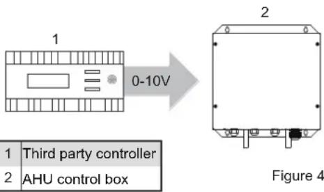
Third party controller - return air temperature control setting
Table 4-9
| Normal | Voltage Range | Cooling Set Temperature (°C) | Heating Set Temperature (°C) | |
| Min. | Max. | |||
| 0.5 | 0 | 0.75 | Not available | Not available |
| 1 | 0.85 | 1.15 | 17 | 17 |
| 1.4 | 1.25 | 1.55 | 17 | 17 |
| 1.8 | 1.65 | 1.95 | 17 | 17 |
| 2.2 | 2.05 | 2.35 | 17 | 17 |
| 2.6 | 2.45 | 2.75 | 17 | 17 |
| 3 | 2.85 | 3.15 | 17 | 17 |
| 3.4 | 3.25 | 3.55 | 17 | 17 |
| 3.8 | 3.65 | 3.95 | 17 | 17 |
| 4.2 | 4.05 | 4.35 | 18 | 18 |
| 4.6 | 4.45 | 4.75 | 19 | 19 |
| 5 | 4.85 | 5.15 | 20 | 20 |
| 5.4 | 5.25 | 5.55 | 21 | 21 |
| 5.8 | 5.65 | 5.95 | 22 | 22 |
| 6.2 | 6.05 | 6.35 | 23 | 23 |
| 6.6 | 6.45 | 6.75 | 24 | 24 |
| 7 | 6.85 | 7.15 | 25 | 25 |
| 7.4 | 7.25 | 7.55 | 26 | 26 |
| 7.8 | 7.65 | 7.95 | 27 | 27 |
| 8.2 | 8.05 | 8.35 | 28 | 28 |
| 8.6 | 8.45 | 8.75 | 29 | 29 |
| 9 | 8.85 | 9.15 | 30 | 30 |
| 9.4 | 9.25 | 10 | Not available | Not available |
Third party controller - outlet air temperature control setting
Table 4-10
| Normal | Voltage Range | Cooling Set Temperature (°C) | Heating Set Temperature (°C) | |
| Min. | Max. | |||
| 0.5 | 0 | 0.75 | Non settable | Non settable |
| 1 | 0.85 | 1.15 | 10 | 10 |
| 1.4 | 1.25 | 1.55 | 11 | 11 |
| 1.8 | 1.65 | 1.95 | 12 | 12 |
| 2.2 | 2.05 | 2.35 | 13 | 13 |
| 2.6 | 2.45 | 2.75 | 14 | 14 |
| 3 | 2.85 | 3.15 | 15 | 15 |
| 3.4 | 3.25 | 3.55 | 16 | 16 |
| 3.8 | 3.65 | 3.95 | 17 | 17 |
| 4.2 | 4.05 | 4.35 | 18 | 18 |
| 4.6 | 4.45 | 4.75 | 19 | 19 |
| 5 | 4.85 | 5.15 | 20 | 20 |
| 5.4 | 5.25 | 5.55 | 21 | 21 |
| 5.8 | 5.65 | 5.95 | 22 | 22 |
| 6.2 | 6.05 | 6.35 | 23 | 23 |
| 6.6 | 6.45 | 6.75 | 24 | 24 |
| 7 | 6.85 | 7.15 | 25 | 25 |
| 7.4 | 7.25 | 7.55 | 26 | 26 |
| 7.8 | 7.65 | 7.95 | 27 | 27 |
| 8.2 | 8.05 | 8.35 | 28 | 28 |
| 8.6 | 8.45 | 8.75 | 29 | 29 |
| 9 | 8.85 | 9.15 | 30 | 30 |
| 9.4 | 9.25 | 10 | Non settable | Non settable |
Note:
The analog voltage must be between maximum and minimum value.
5 DIP DEFINITION
NOTE
0 means DIP switch is dialled to "OFF" 1 means DIP switch is dialled to "ON"
1) Definitions of each bit of SW1:
 Valid for the master unit only Valid for the master unit only | SW1-1 is 0: shutdown compensation temperature (cooling) is 0^ (factory default)SW1-1 is 1: shutdown compensation temperature (cooling) is 2^ (outlet air temperature control is invalid) |
 Valid for the master unit only Valid for the master unit only | SW1-2 is 0: AHU control box provides three fan speeds (factory default)SW1-2 is 1: only one fan speed |
 Valid for the master unit only Valid for the master unit only | SW1-3 and SW1-4 are 00: the number of slave AHU control boxes connected in parallel is 0 (factory default); valid for the master unit |
 Valid for the master unit only Valid for the master unit only | SW1-3 and SW1-4 are 01: the number of slave AHU control boxes connected in parallel is 1 |
 Valid for the master unit only Valid for the master unit only | SW1-3 and SW1-4 are 10: the number of slave AHU control boxes connected in parallel is 2 |
 Valid for the master unit only Valid for the master unit only | SW1-3 and SW1-4 are 11: the number of slave AHU control boxes connected in parallel is 3 |
2) Definitions of each bit of SW2:
 | SW2-1 is 0: automatic addressing (factory default)SW2-1 is 1: clearing AHU control box address |
 | SW2-2 is 0: no self-check (factory default)SW2-2 is 1: self-check |
 | SW2-3 and SW2-4 are 00: master AHU control box(factory default) |
 | SW2-3 and SW2-4 are 01: slave AHU control box 1 |
 | SW2-3 and SW2-4 are 10: slave AHU control box 2 |
 | SW2-3 and SW2-4 are 11: slave AHU control box 3 |
3) Definitions of each bit of SW3:
| Return Air Temperature Control (SW4-1 is 0) Outlet | Air Temperature Control (SW4-1 is 1) | |
 Valid for the master unit only Valid for the master unit only | SW3-1 and SW3-2 are 00: anti-cold air temperature value in heating mode is 15^ (factory default) | SW3-1 and SW3-2 are 00: anti-cold air temperature value in heating mode is 14^ |
 Valid for the master unit only Valid for the master unit only | SW3-1 and SW3-2 are 01: anti-cold air temperature value in heating mode is 20^ | SW3-1 and SW3-2 are 01: anti-cold air temperature value in heating mode is 12^ |
 Valid for the master unit only Valid for the master unit only | SW3-1 and SW3-2 are 10: anti-cold air temperature value in heating mode is 24^ | SW3-1 and SW3-2 are 10: anti-cold air temperature value in heating mode is 16^ |
 Valid for the master unit only Valid for the master unit only | SW3-1 and SW3-2 are 11: anti-cold air temperature value in heating mode is 26^ | SW3-1 and SW3-2 are 11: anti-cold air temperature value in heating mode is 18^ |
 Valid for the master unit only Valid for the master unit only | SW3-3 and SW3-4 are 00: temperature compensation in heating mode is 6^ (factory default) | SW3-3 and SW3-4 are 00: Outlet air temperature control is invalid |
 Valid for the master unit only Valid for the master unit only | SW3-3 and SW3-4 are 01: temperature compensation in heating mode is 2^ | SW3-3 and SW3-4 are 01: Outlet air temperature control is invalid |
 Valid for the master unit only Valid for the master unit only | SW3-3 and SW3-4 are 10: temperature compensation in heating mode is 4^ | SW3-3 and SW3-4 are 10: Outlet air temperature control is invalid |
 Valid for the master unit only Valid for the master unit only | SW3-3 and SW3-4 are 11: temperature compensation in heating mode is 0^ (Follow Me function) | SW3-3 and SW3-4 are 11: No temperature compensation for outlet air temperature control by default |
4) Definitions of each bit of SW4:
 Valid for the master unit only Valid for the master unit only | SW4-1 is 0: return air temperature control (factory default)SW4-1 is 1: outlet air temperature control | ON1234Valid for the master unit only | SW4-2 indicates high bit (ON indicates + 16) |
 Valid for the master unit only Valid for the master unit only | SW4-3 and SW4-4 are 00: factory controller mode (factory default) | ON1234Valid for the master unit only | SW4-3 and SW4-4 are 01: capacity output mode of a third party controller |
 Valid for the master unit only Valid for the master unit only | SW4-3 and SW4-4 are 10: set temperature control mode of a third party controller | ON1234Valid for the master unit only | SW4-3 and SW4-4 are 11: set temperature control mode of a third party controller (reserved) |
5) Definitions of each bit of SW9:
| [2327]Valid for the master unit only | SW9-1 is 0: 2-digit digital display panel (factory default)SW9-2 is 1: 3-digit digital display panel |
 Valid for the master unit only Valid for the master unit only | SW9-2 is 0: One or more AHU control boxes are connected in parallel to one AHU; one coil is connected to multiple control boxes; (shielding faults from the slave unit's temperature sensors T1, T2, T2A, TA and T2B) (factory default)SW9-2 is 1: Multiple AHU control boxes are connected in parallel. In the event of multiple coils, one coil is connected to one control box; (shielding faults from the slave unit's temperature sensor T1,TA) |
 Valid for the master unit only Valid for the master unit only | SW9-3 is 0: no swing control (factory default)SW9-3 is 1: swing control |
6) Definitions of each bit of SW10:
| 00: AHUKZ-00D model | |
| 01: AHUKZ-01D model | |
| 10: AHUKZ-02D model | |
| 11: AHUKZ-03D model |
7) Definitions of J1:
| Without jumper; no short circuit indicates a power failure memory function (factory default) | |
| With jumper, short circuit indicates no power failure memory function |
6 ERROR CODE AND QUERY
Error Code
| Priority | Definition | Displayed content |
| 1 | Rcfrigerant leak error | A1 |
| 2 | Emergency shut down | A0 |
| 3 | No address is set | FE (only displayed on the display board) |
| 4 | IDU address code repeated→ F7+repeated address, displayed alternately every 1s | F7+repeated address |
| 5 | Mode conflict error | E0 |
| 6 | Communication error between IDU and ODU | E1 |
| 7 | T1 sensor error | E2 |
| 8 | T2 sensor error | E3 |
| 9 | T2B sensor error | E4 |
| 10 | T2A sensor error | E5 |
| 11 | IDU fan error | E6 (reserved) |
| 12 | EEPROM error | E7 |
| 13 | TA sensor error | E8 (the error is not reported when return air temperature control is applied) |
| 14 E9 | Communication error with the wired controller, (only for wired controller) or no address is setted | |
| 15 | Error of electronic expansion valve coils | Eb (restore after power on again) |
| 17 Ed | ODU error | |
| 18 | Water level alarm error | EE |
| 19 | Low temperature alarm | H2 |
| 20 | High temperature alarm | H3 |
| 21 | The number of detected AHU control boxes and the number of dialing units are inconsistent, or Master-slave communication is not available | H6 |
| 22 | Capacity DIP switch of the AHU control box is inconsistent with model | H8 (restore after power on again) |
| 23 | (ENC2,ENC3,ENC4)incorrect DIP switch for 0-10V fan signal.The DIP switch value ensures ENC2 < ENC3 < ENC4 . | H9 (restore after power on again) |
| 24 P1 | (Persessured)sensor error | |
| 25 | MS error mode | F8 |
| 26 | MS self-check error | U4 (restore after power on again) |
| 27 Slave unit error Hb | ||
Query
Wired controller query
| No. | No. Parameter displayed on the wired controller during control box check |
| 1 | Control box communication address |
| 2 | Capacity (HP) of control box |
| 3 | Control box network address (the same as the communication address) |
| 4 | Set temperature Ts |
| 5 | Room temperature T1 |
| 6 | Actual T2 AHU temperature |
| 7 | Actual T2A AHU temperature |
| 8 | Actual T2B AHU temperature |
| 9 | TA temperature |
| 10 | Compressor discharge temperature (show high discharge temperature) |
| 11 | Target superheat degree (reserved) |
| 12 | EEV position/8 |
| 13 | Software version No. |
| 14 | Error Code |
HTW
QUALITY COMFORT EVERYWHERE

GROUP
make your life easy
info@htwspain.com - www.htwspain.com
FRANCE
info@htwfrance.com
PORTUGAL
info@htw.pt
ITALIA
info.it@htwspain.com

IMPORTANT INFORMATION FOR CORRECT DISPOSAL OF THE PRODUCT IN ACCORDANCE WITH EC DIRECTIVE 2002/96/EC. At the end of its working life, the product must not be disposed of as urban waste. It must be taken to a special local authority deifferentiated waste collection centre or to a dealer providing this service. Disposing of a household appliance separately avoids possible negative consequences for the environment and health deriving from inappropriate disposal and enables the constituent materials to be recovered to obtain significant savings in energy and resources. As a reminder of the need to dispose of household appliances separately, the product is marked with a crossed-outwheeled dustbin.
- AHUKZ
- HTW
- CONTENTS
- PRECAUTIONS 01
- INTRODUCTION 02
- INSTALLATION
- FUNCTION SETTINGS
- DIP DEFINITION 23
- ERROR CODE AND QUERY 26
- PRECAUTIONS
- CAUTION
- WARNING
- INTRODUCTION
- Before Installation
- NOTE
- Choosing an Installation Site
- Installation Methods and Size
- Refrigerant Piping
- Material and Size of the Piping
- Pipe Limits
- Welding Precautions
- AHU Control Box Installation
- Pipe classification
- Size of joint pipe for R410A DX AHU
- Example
- Other piping methods for example.
- Single VRF DX AHU Control Box connect to one AHU
- Temperature Sensor Installation
- Electrical Connection
- Circuit Diagram
- Wiring Inside the Electric Control Box
- Refer to Fan wiring
- Temperature Sensor Wiring 3.6.4 Cross section of main power cable
- Fan Wiring
- : Refer to 0-10V output control
- 0-10V Output control
- SW1-2 dialled to "ON"
- Wiring between the terminal block and fan
- Note:
- Signal Cable Connection
- Example of signal wiring(Heat pump)
- Capacity Settings
- Setting the Master/Slave AHU Control Box
- Address Settings of AHU Control Box
- Single AHU Control Box Controlling One AHU
- Several AHU Control Boxes in a Parallel Connection Controlling One AHU
- Selection of Control by Return Air Temperature or by Outlet Air Temperature
- Selection of Controllers
- Factory Controller
- Setting Capacity Output Mode via a Third Party Controller (Type 1)
- Third party controller wiring
- The definition of signals between the third party controller and AHU control box.
- Operation at 0-10V capacity output
- Operation instruction
- Setting Temperature Mode via a Third Party Controller (Type 2)
- Definition of signals between the third party controller and the AHU control box
- Operation at 0-10V temperature output
- DIP DEFINITION
- ERROR CODE AND QUERY
- Query
- QUALITY COMFORT EVERYWHERE
Brand : HTW
Model : AHUKZ
Category : Air conditioner