
1537 - Measurement FLUKE - Free user manual and instructions
Find the device manual for free 1537 FLUKE in PDF.


| Product Type | High-Voltage Insulation Tester |
| Model | Fluke 1537 |
| Test Voltage (Preset) | 250 V, 500 V, 1000 V, 2500 V |
| Programmable Test Voltage | 250 V to 2500 V in 100 V steps (1537 only) |
| Insulation Measurement Range | 200 kΩ to 500 GΩ |
| Resistance Measurement (DMM) | 0 Ω to 60 kΩ (1537 only) |
| AC/DC Voltage Measurement | 0 V to 600.0 V (1537 only) |
| Special Functions | PI, DAR, DD, Ramp test, Timer, Memory (99 records), Breakdown detection (1537) |
| Display | Large LCD with bargraph, backlight |
| User Interface | Pushbuttons for test voltage, test start/stop, function selection, navigation |
| Data Storage | Up to 99 test records with custom ID tags (1537 only) |
| PC Connectivity | USB port for data download (1537 only) |
| Power Source | 6 AA batteries (included) |
| Battery Life | Approximately 1300 to 6500 measurements depending on voltage |
| Dimensions (Approx.) | 220 mm x 120 mm x 50 mm |
| Weight (Approx.) | 1 kg (with batteries) |
| Safety Ratings | CAT III 600 V, CAT IV 300 V; Double insulation |
| Warranty | 3 years (1 year for 1535) |
| Included Accessories | Test leads (red, black, green), alligator clips, soft carrying case, quick reference guide, USB cable (1537) |
| Cleaning | Damp cloth with mild detergent; no abrasives |
| Spare Parts Available | Test leads, probes, clips, case, USB cable |
| Guard Terminal | Yes, for high-resistance measurements to eliminate surface leakage |
| Auto Power Off | After 10 minutes of inactivity |
Frequently Asked Questions - 1537 FLUKE
User questions about 1537 FLUKE
0 question about this device. Answer the ones you know or ask your own.
Ask a new question about this device
Download the instructions for your Measurement in PDF format for free! Find your manual 1537 - FLUKE and take your electronic device back in hand. On this page are published all the documents necessary for the use of your device. 1537 by FLUKE.
USER MANUAL 1537 FLUKE
The Fluke 1537 will be free from defects in material and workmanship for three years from the date of purchase.
The Fluke 1535 will be free from defects in material and workmanship for one year from the date of purchase.
This warranty does not cover fuses, disposable batteries, or damage from accident, neglect, misuse, alteration, contamination, or abnormal conditions of operation or handling. Resellers are not authorized to extend any other warranty on Fluke's behalf. To obtain service during the warranty period, contact your nearest Fluke authorized service center to obtain return authorization information, then send the product to that Service Center with a description of the problem.
THIS WARRANTY IS YOUR ONLY REMEDY. NO OTHER WARRANTIES, SUCH AS FITNESS FOR A PARTICULAR PURPOSE, ARE EXPRESSED OR IMPLIED. FLUKE IS NOT LIABLE FOR ANY SPECIAL, INDIRECT, INCIDENTAL OR CONSEQUENTIAL DAMAGES OR LOSSES, ARISING FROM ANY CAUSE OR THEORY. Since some states or countries do not allow the exclusion or limitation of an implied warranty or of incidental or consequential damages, this limitation of liability may not apply to you.
Fluke Corporation
P.O. Box 9090
Everett, WA 98206-9090
U.S.A.
China Service Center
Rm 101, 1/F, Tong Heng Tower
No. 4 Hua Yuan Road,
Hai Dian District, Beijing
100088, P.R.C.
Hotline: 400 921 0835
Table of Contents
Introduction.... 1
Contact Fluke 2
Safety Information 2
Symbols.... 5
Unpack the Tester 6
The Tester.... 7
Pushbuttons.... 7
Tester On/Off.... 9
Display.... 10
Guard Terminal Use.... 11
Test Circuit Connections 13
Before an Insulation Test.... 14
Preset Test Voltage Selection 15
Program a Test Voltage (1537 only) 15
Select a Ramp or Steady-State Test (1537 only).... 16
Set a Timed Test (1537 only) 16
Polarization Index (PI).... 17
Dielectric Discharge (1537 only).... 17
Dielectric Absorption Ratio.... 18
Insulation Test.... 18
Store Test Results (1537 only).... 20
View Test Results Stored in Memory (1537 only).... 21
Delete Test Results Stored in Memory (1537 only) 23
V ac / V dc / Resistance (1537 only).... 23
1537 PC Software.... 24
Maintenance 25
Cleaning.... 25
Battery Replacement.... 25
Parts and Accessories.... 26
General Specifications.... 28
Electrical Specifications.... 28
Principle of Measurement and Resistance 32
Introduction
The Fluke 1535/1537 Insulation Testers (the Tester or Product) are high-voltage insulation testers to validate general circuits, such as switchgear, motors, and cables.
The Tester features:
• Large liquid crystal display (LCD)
- Preset test voltages: 250 V, 500 V, 1000 V, 2500 V
• Insulation measurement: 200 kΩ to 500 GΩ
- Polarization Index (PI) measurement
• Dielectric Absorption Ratio (DAR) measurement
• Auto power off after 10 minutes of inactivity
The 1537 also includes:
• V ac/V dc/Resistance measurement
• Programmable test voltages: 250 V to 2500 V in 100 V steps
• Dielectric Discharge (DD) measurement
- Ramp mode that linearly increases (100 V/s) the applied test voltage
- Test timer and storage for test results with user-defined ID tag
- Breakdown voltage indication
- Mini USB serial port for download of test data
- PC software
Contact Fluke
Fluke Corporation operates worldwide. For local contact information, go to our website: www.fluke.com.
To register your product, or to view, print, or download the latest manual or manual supplement, go to our website.
Fluke Corporation
Fluke Europe B.V.
P.O. Box 9090
P.O. Box 1186
Everett WA 98206-9090
5602 BD Eindhoven
U.S.A.
The Netherlands
+1-425-446-5500 fluke-info@fluke.com
Safety Information
A Warning identifies hazardous conditions and procedures that are dangerous to the user. A Caution identifies conditions and procedures that can cause damage to the Product or the equipment under test.
Warning
To prevent possible electrical shock, fire, or personal injury:
- Carefully read all instructions.
- Read all safety information before you use the Product.
- Do not alter the Product and use only as specified, or the protection supplied by the Product can be compromised.
- Do not use the Product around explosive gas, vapor, or in damp or wet environments.
- Do not use the Product if it is altered or damaged.
- Disable the Product if it is damaged.
- Do not use the Product if it operates incorrectly.
- Use Product-approved measurement category (CAT), voltage, and amperage rated accessories (probes, test leads, and adapters) for all measurements.
-
Do not exceed the Measurement Category (CAT) rating of the lowest-rated individual component of a Product, probe, or accessory.
-
Do not use in CAT III or CAT IV environments without the protective cap installed on test probe. The protective cap decreases the exposed probe metal to <4 mm. This decreases the possibility of arc flash from short circuits.
- Comply with local and national safety codes. Use personal protective equipment (approved rubber gloves, face protection, and flame-resistant clothes) to prevent shock and arc blast injury where hazardous live conductors are exposed.
- Examine the case before you use the Product. Look for cracks or missing plastic. Carefully look at the insulation around the terminals.
- Do not use test leads if they are damaged. Examine the test leads for damaged insulation and measure a known voltage.
- Do not touch voltages >30 V ac rms, 42 V ac peak, or 60 V dc.
- Do not apply more than the rated voltage, between the terminals or between each terminal and earth ground.
- Measure a known voltage first to make sure that the Product operates correctly.
- Limit operation to the specified measurement category, voltage, or amperage ratings.
- The battery door must be closed and locked before you operate the Product.
- Connect the common test lead before the live test lead and remove the live test lead before the common test lead.
- Remove all probes, test leads, and accessories before the battery door is opened.
- Remove all probes, test leads, and accessories that are not necessary for the measurement.
- Keep fingers behind the finger guards on the probes.
- Replace the batteries when the low battery indicator shows to prevent incorrect measurements.
- Use the correct terminals, function, and range for measurements.
- Place test leads in proper input terminals.
- Do not work alone.
- Do not use in distribution systems with voltages higher than 660 V.
- Use only recommended test leads.
- Remove all power from the circuit under test and discharge circuit capacitance before testing resistance or capacitor with the tester.
- Results of measurement can be adversely affected by the impedances of additional operating circuits connected in parallel or by transient currents.
- Before and after testing, confirm that the Tester does not indicate the presence of a hazardous voltage. If a hazardous voltage is shown on the display, remove power from the circuit under test or allow the installation capacitance to fully discharge.
- Do not disconnect the test leads before a test has been completed and the test voltage at the terminals has returned to zero. This ensures that any charged capacitance is fully discharged.
- Use the guard terminal only as specified in this manual. Do not allow other foreign objects to come into contact with the guard terminals as safety may be compromised.
- Remove the input signals before you clean the Product.
- Use only specified replacement parts.
- Repair the Product before use if the battery leaks.
- Be sure that the battery polarity is correct to prevent battery leakage.
- Do not operate the Product with covers removed or the case open. Hazardous voltage exposure is possible.
- Have an approved technician repair the Product.
Symbols
Table 1 lists the symbols used on the Tester and in the manual.
Table 1. Symbols
| Symbol Definition | |
| [TWX0] | WARNING. HAZARDOUS VOLTAGE. Risk of electric shock. |
| [DX6H] | WARNING. RISK OF DANGER. |
| [T72S] | Consult user documentation. |
| [YVXA] | Conforms to European Union directives. |
 | Battery |
 | Continuity test or continuity beeper tone. (1537 only) |
| [K750] | Double Insulated |
| [SWW2] | WARNING. Do not apply greater than 660 Volts. |
 | Interference is present. Displayed value might be outside of specified accuracy. |
| RAMP Ramp mode indicator | |
 | Electrical breakdown |
| [KS26] | Both direct and alternating current |
 | Earth |
 | Measurement Category III is applicable to test and measuring circuits connected to the distribution part of the building's low-voltage MAINS installation. |
| [8DS8] | Measurement Category IV is applicable to test and measuring circuits connected at the source of the building's low-voltage MAINS installation. |
| [TT2H] | This product complies with the WEEE Directive marking requirements. The affixed label indicates that you must not discard this electrical/electronic product in domestic household waste. Product Category: With reference to the equipment types in the WEEE Directive Annex I, this product is classed as a category 9 “Monitoring and Control Instrumentation” product. Do not dispose of this product as unsorted municipal waste. |
Unpack the Tester
The Tester includes these items:
• Insulation Tester (includes batteries)
- Quick Reference Guide
- Test Cables with Alligator Clips (red, black, green)
- Soft Carrying Case
• Test Report
The 1537 also includes a USB Cable.
See Table 9 for a list of parts. If the Tester is damaged or an item is missing, contact the place of purchase.
The Tester
Table 2 shows the location of the Tester features.
Table 2. Features
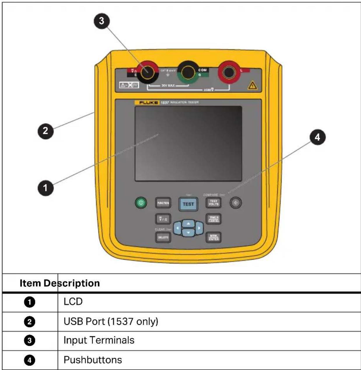
Pushbuttons
Table 3 shows the location of each pushbutton and describes the functions.
Table 3. Pushbuttons
| 10 9 8 | |||
| Item Description | Model | ||
| 1535 1537 | |||
| ① | Power On / Power Off | ● | ● |
| ② | DAR / PI / DAR + PI Selection | ● | |
| DAR / PI / DAR + PI / DD / Ramp Selection | ● | ||
| ③ | Test Start/Stop: Push and hold for 1 s to start a test. Push again to stop a test. | ● | ● |
| ④ | Voltage Setting: 250 V / 500 V / 1000 V / 2500 V | ● | ● |
| Resistance Setting: value comparison | ● | ||
| ⑤ | Backlight On/Off | ● | ● |
| ⑥ | Test Time Set/Cancel | ● | |
| ⑦ | Record/Enter | ● | |
| ⑧ | scrolls through the test results stored in memory for all records. scrolls through available test parameters for selected function. | ● | |
| ⑨ | Delete Data | ● | |
| ⑩ | V ac / V dc / Resistance Selection | ● | |
Also use ▲ ▼ to access these menu items:
• Voltage adjustment in 100 V for each step
- Time limit xx-xx
- T - 0 to 99 minutes
T1, T2, T3 - T1 < T2 < T3
T1 > 0 seconds, T3 < 1000 seconds
• Show test parameters
- Change the name of the ID tag for the test result
• P u MEM. ENTER to make the selection.
Tester On/Off
Push Ⓐ to turn on the Tester.
The Tester does a self-check, shows the software version, and starts in the Insulation Resistance Idle mode.
In Insulation Resistance Idle mode:
- Change test parameters
- Start an insulation test
• View stored test results (1537 only) - Download test results (1537 only)
Caution
If the object under test is highly capacitive, it can take a long time for the Product to discharge. Do not turn off the Product or remove test leads until the discharge is complete.
When on, push ⏻ >1 second to turn off the Tester.
Display
Table 4 shows the location of each display feature.
⚠ Warning
To prevent possible electrical shock, fire, or personal injury:
- Before and after any tests, do a voltage test to confirm that the Tester does not detect the presence of hazardous voltage.
- If the Tester beeps continuously before the insulation test starts and there is hazardous voltage, disconnect test leads and remove power from the circuit under test.
Table 4. Display Features
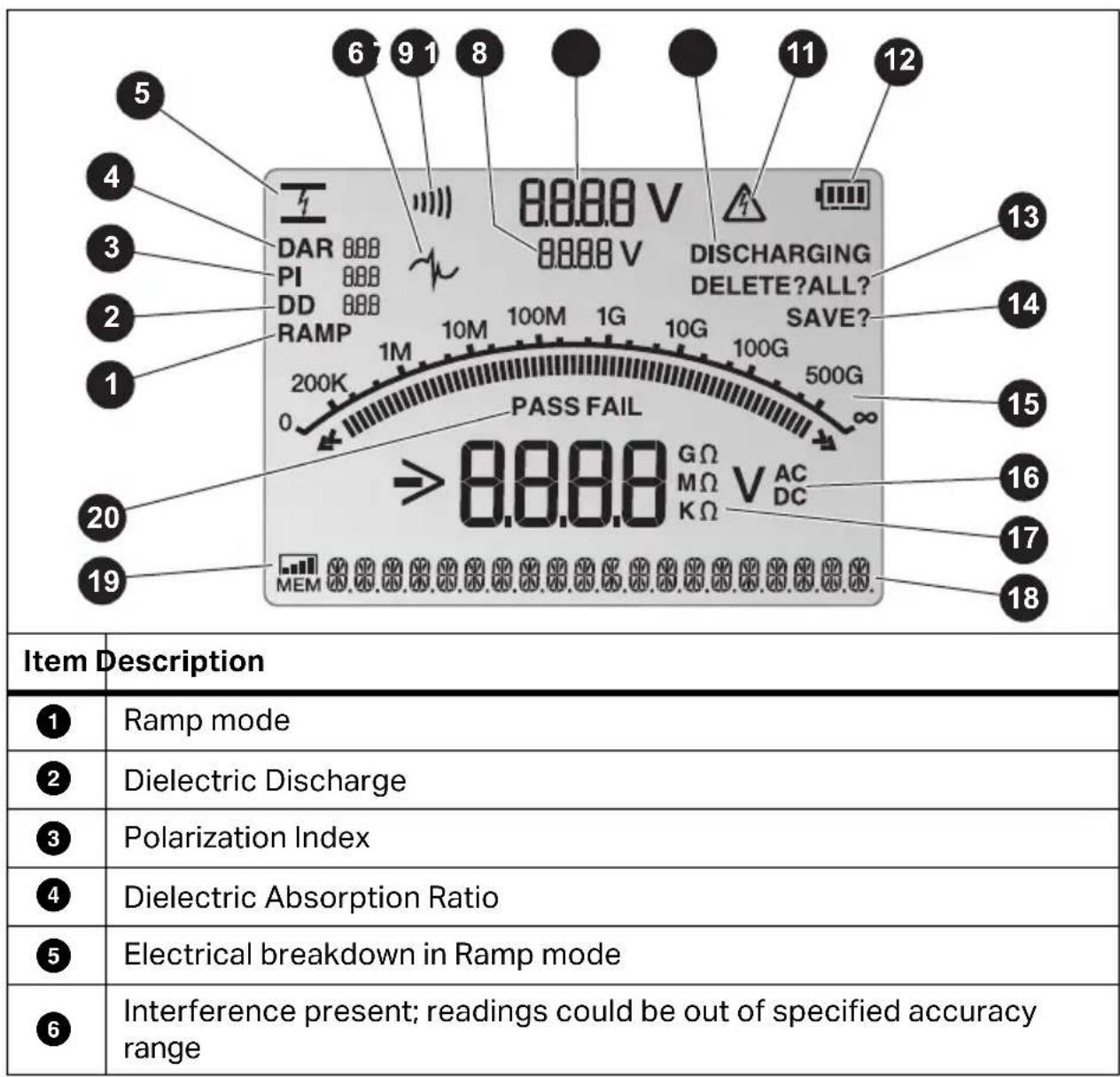
Table 4. Display Features (cont.)
| 7 | Continuity (1537 only) |
| 8 | Test Voltage Setting |
| 9 | Test Voltage |
| 10 | Discharging |
| 11 | Possible hazardous voltage is at the test terminals |
| 12 | Battery Status |
| 13 | Delete/Delete All |
| 14 | Save |
| 15 | Bar graph display of insulation resistance |
| 16 | V ac or V dc voltage indicator |
| 17 | Insulation and DMM resistance measurement indicator |
| 18 | Text display; shows voltage, test current, capacitance, programmable test voltages, and menu options |
| 19 | Memory Status |
| 20 | Pass/Fail |
Guard Terminal Use
Note
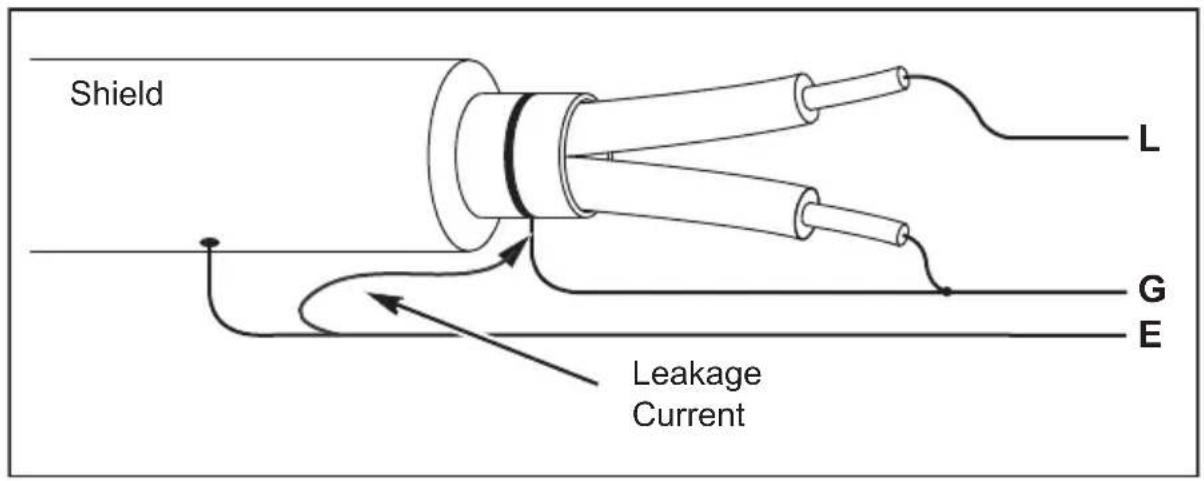
Insulation resistance is measured between the Earth terminal (E) and Live terminal (L) output connections. The Guard terminal (G) is at the same potential as the E terminal but is not in the measurement path.
For most tests, use only two test leads. Connect the E and L test leads to the corresponding inputs on the Tester. Connect the test lead probes to the circuit under test. The Guard (G) terminal is left unconnected.
For the best accuracy when you measure very high resistances, use three-wire measurements including G. G is at the same potential as E, and can be used to prevent surface leakage or other unwanted leakage currents from degrading the accuracy of the insulation resistance measurement.
Figure 1 shows how to measure the resistance from one of the conductors to the outer shield. In this case, there is a leakage current along the surface of the inner insulation near the end of the cable. This leakage adds to the current that the negative terminal senses, and causes the Tester to read a lower resistance than it should.
Figure 1. Surface Leakage Current
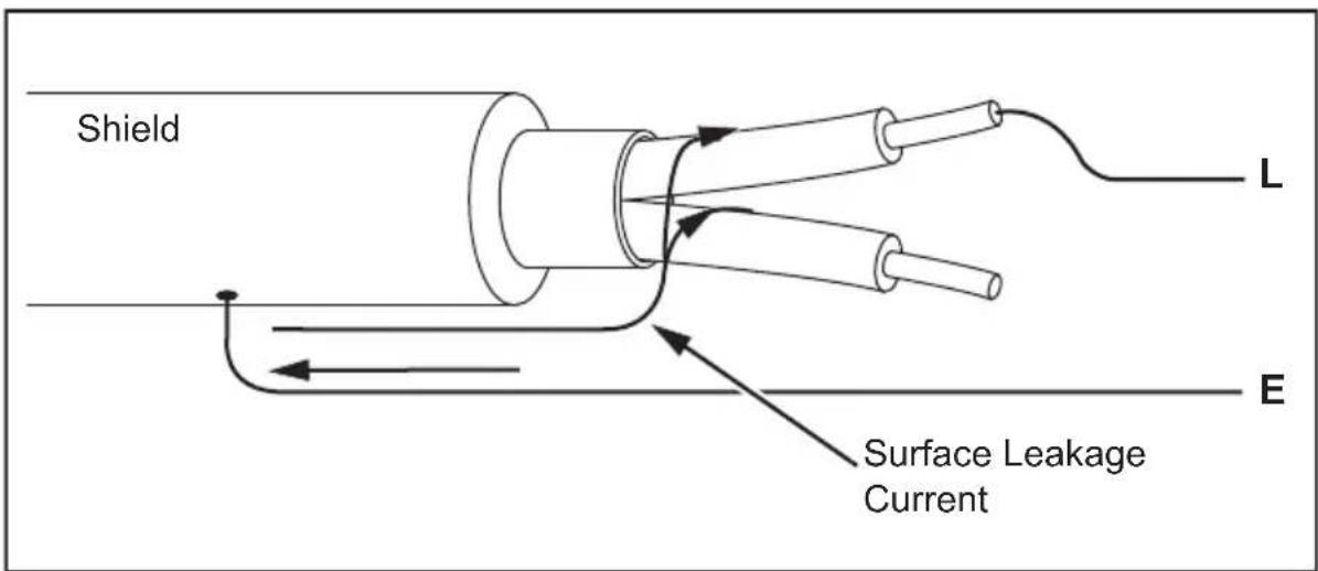
Figure 2 shows how to prevent surface current leakage with a lead connected from the Guard terminal to a conductor that surrounds the inner insulation. The surface leakage current is directed to the Guard terminal. This removes the leakage current from the measurement path between the positive and negative terminals, and improves the accuracy of the test readings.
Figure 2. Guard Terminal Connection
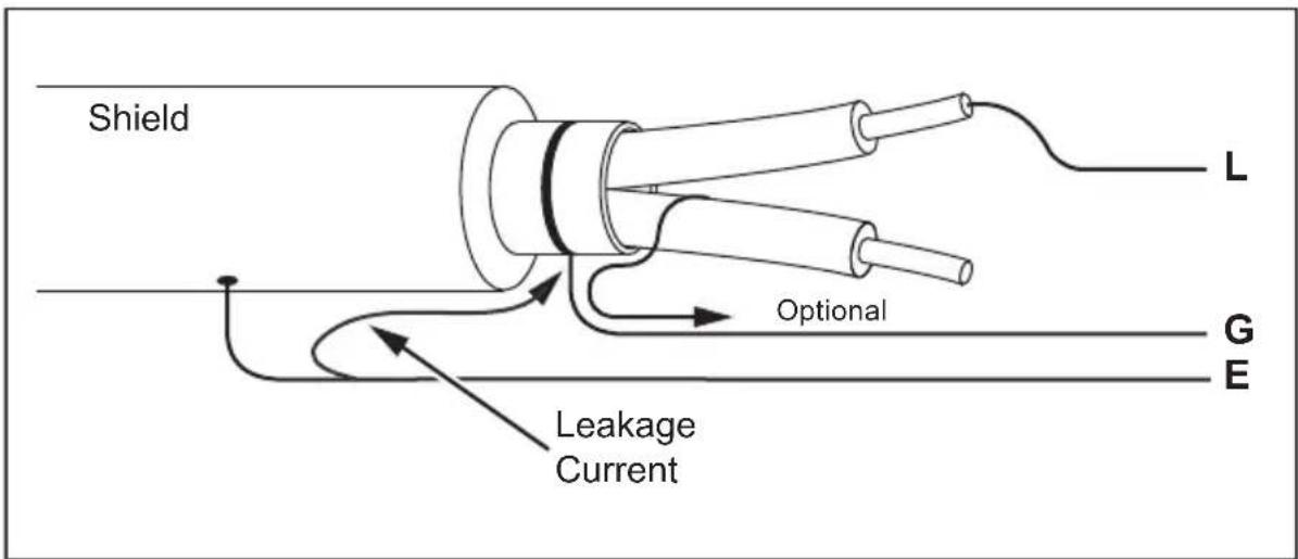
Figure 3 shows how make the measurement setup better. Connect the Guard terminal to the unused wire and attach it to the inner insulation. This ensures that the Tester measures the leakage between the selected conductor and the outer shield, but removes the leakage path between conductors.
Figure 3. Improved Guard Terminal Connection
Test Circuit Connections
Warning
To prevent possible electric shock or personal injury:
- Disconnect power and discharge all high-voltage capacitors before you measure resistance.
- Connect the Earth (E) test lead before the live (L) test lead and remove the L test lead before the E test lead.
- Before and after tests, do a voltage test to confirm that the Tester does not detect the presence of hazardous voltage. See Table 4. If a hazardous voltage is shown on the display, remove power from the circuit under test and disconnect test leads.
To connect to the circuit under test:
- Put the test leads into the correct terminals. See Table 5.
- Connect the test leads to the circuit under test.
Table 5. Test Lead Connections
| 1 E L 2 | |
| Item Description | |
| ① | E - Earth Terminal |
| ② | L - Live Terminal |
Note
The Tester does not have specified accuracy below 200 kΩ. When you do a test below 200 kΩ or with the leads shorted, the Tester can show a reading. This is normal for the input circuitry configuration for this Tester. Only the readings within the specified accuracy range are accurate.
Before an Insulation Test
The Tester includes features that let you adapt the test to your requirements. You can:
- Define a test voltage
• Measure polarization index (PI)
• Measure dielectric absorption ratio (DAR)
1537 only:
- Make a ramp test selection
• Measure dielectric discharge (DD) - Compare insulation resistance
- Set a time limit/duration for the test
Use these features alone or in combination. Configure or validate (as appropriate) each feature before you start an insulation test.
Preset Test Voltage Selection
To make a preset test voltage selection:
- Turn on the Tester.
- Push TEST VOLTS to scroll through the preset test voltage options (250 V, 500 V, 1000 V, 2500 V).
The test voltage selection shows on the display.
Note
The actual test voltage can be up to 10 % higher than the selected test voltage.
Program a Test Voltage (1537 only)
To set a test voltage in between the preset test voltages, proceed as follows:
- Turn on the Tester.
- Push TEST VOLTS to select the test voltage.
- Continue to push TEST VOLTS to scroll through the preset test voltage options (250 V, 500 V, 1000 V, 2500 V). Select the voltage closest to the level required.
The test voltage selection shows on the display.
Push ▲ or ▼ to increase and decrease the voltage in 100 V steps until the correct voltage level shows.
Note
The test voltage can be up to 10 % higher than the test voltage you select.
Select a Ramp or Steady-State Test (1537 only)
The ramp test function is an automated test that checks insulation for a breakdown. During a ramp test, the output voltage starts at 0 V and increases linearly (100 V/s) until it reaches the specified test voltage or until the Tester senses a sudden drop in measured resistance.
If the Tester senses a sudden drop in resistance:
- R a m p s t o p s
- Tester automatically discharges
If the test successfully meets compliance without breakdown, the result is the same as a normal insulation test and shows the data.
To enable or disable the ramp function:
-
With the Tester turned on, push FUNCTION to go to the Ramp test function. When the ramp test is on, RAMP shows on the display.
-
Push TEST for 1 second to start the test.
Set a Timed Test (1537 only)
You can control the duration of an insulation test by setting a timer. The time (test duration) can be set in 1-minute increments up to 99 minutes.
At the end of the elapsed time, the insulation test is complete and the test stops.
To set a test time limit:
- With the Tester turned on, push TIMER CANCEL to enter the Timed Test Menu.
- Push ▲ or ▼ to configure the time.
- Push MEM. ENTER to set the time limit.
- Push TEST for 1 second to start the test.
Polarization Index (PI)
As part of the insulation test, the Tester measures and stores polarization index (PI), when appropriate. A polarization index test requires 10 minutes to complete. Therefore, the Tester will start a countdown at 10 minutes. When an insulation test reaches 10 minutes, the polarization test is complete. The results are available for display during a test or when you store the test results and view the record PI field. The field is identified by:
$$ P I = \frac {R _ {\mathrm{min10}}}{R _ {1 \mathrm{min}}} $$
Dielectric Discharge (1537 only)
The dielectric discharge (DD) test, also known as the re-absorption current test, is a measurement of the current during dielectric discharge of the equipment being tested.
The measurement principle is as follows:
- Equipment to be tested is first charged for 30 minutes to reach a stable state (capacitance charging and polarization are completed and the only current flowing is the leakage current).
- Equipment is then discharged through a resistor inside the mega-ohmmeter and the current that flows is measured. This current is made up of the capacitance charging current and the re-absorption current that combines to give the total dielectric discharge current. This current is measured after a standard time of 1 minute. The current depends on the overall capacitance and the final test voltage.
The value DD is calculated with this formula:
$$ D D = \frac {I}{V \times C} $$
I = current after 1-minute discharge
V = voltage after 1-minute discharge
C = measured object capacitor
Dielectric Absorption Ratio
If appropriate, as part of the insulation test, the Tester stores the dielectric absorption ratio (DAR) with the measurement. A DAR test has a 1-minute duration and is measured and stored as invalid data for all insulation tests <1 minute. The DAR test automatically stops when the insulation test time reaches 1 minute. The results are available for display after test or by storing the test results and viewing the DAR field in record. The field is identified by:
$$ D A R = \frac {R @ 1 m i n}{R @ 3 0 s e c} $$
The Tester also does the DAR test in accordance with the Chinese standards:
$$ D A R [ C N ] = \frac {R @ 1 m i n}{R @ 1 5 s e c} $$
Note
If appropriate, as part of the insulation test, the Tester stores the capacitance measurement. The results are available for display after the test is complete by viewing the capacitance field in the stored record.
Insulation Test
⚠️ Warning
To prevent possible electric shock or personal injury:
- Be aware that measuring insulation resistance requires the application of potentially dangerous voltages to the circuit. This may include exposed bonded metalwork.
- Remove all power from the circuit under test and discharge circuit capacitance before testing a circuit with the Tester.
- Before a test starts, ensure that the installation is wired correctly and no personnel are endangered by any tests.
- Connect the test leads to the Tester inputs before you make any connections to the circuit under test.
PI/DAR is valid in these conditions:
• Capacitance is ≤0.1 μF or Resistance is ≤100 MΩ.
• Resistance is ≥200 k and Capacitance ≤2 F.
- Current is ≥ 50 nA.
To do an insulation test:
-
With the Tester turned on, set the available measurement options to meet your test requirements. These include:
-
Test Voltage – Set range: 250 V to 2500 V (1537 only: 100 V steps)
-
Ramp Test – (optional, 1537 only)
• Time Limit – (optional, 1537 only) -
Connect the probes to the circuit under test.
Warning
To prevent possible electric shock or personal injury:
- Before and after tests, do a voltage test to confirm that the Tester does not detect the presence of hazardous voltage. See Table 4.
-
If the Tester beeps continuously before the insulation test starts and there is hazardous voltage, disconnect test leads and remove power from the circuit under test.
-
Push TEST for 1 second to start the insulation test.
The Tester makes three beeps as the test begins, and ⚠ flashes on the display to indicate potentially hazardous voltages may be present on the test terminals.
The display shows the insulation resistance after the circuit stabilizes. The bar graph shows this value continuously (in real time) as a trend. See Table 6.
Table 6. Insulation Resistance Measurements
| 104 GΩ | |
| Item Description | |
| ① | Digital main display |
| ② | Bar graph |
Any of the following conditions will stop an insulation test:
- User stops the test (push TEST)
• Time limit is complete (1537 only)
• Interference on the test circuit - Breakdown occurs with ramp test enabled (1537 only)
• DAR / PI / DD reaches time limit - Battery is depleted
When the insulation test is done, the Tester beeps if a potentially hazardous voltage remains on the test terminals due to charged-circuit capacitance or from the presence of an external voltage.
- When the test is done, the Tester shows a prompt to store the results. If appropriate, store the test results (see next section). Otherwise, push to bypass the prompt. The results are not stored.
Store Test Results (1537 only)
When the insulation test is done, the Tester shows a prompt to save the results. The Tester memory stores the results of up to 99 insulation tests.
To store the results of an insulation test:
-
Push MEM ENTER to save the measurement results. The Tester assigns and displays a sequential tag number to identify the measurement.
-
If the tag number is acceptable, push MEM. ENTER to store the data. If a different tag convention is required, create a custom 4-character tag:
a. Notice that the active character is blinking on the display. This is the first of the four characters available for tagging the test results. Repeatedly push ◀▶ to cycle through the character positions.
b. At each character position use ▲ or ▼ to assign a character (0-9, A-Z, a-z).
c. Push MEM. ENTER to store the results.
View Test Results Stored in Memory (1537 only)
Note
Parameters not appropriate for a test are shown as NA or UNSPEC.
The Tester can store 99 sets of test data, including:
- Tags
- Ramp on or off
• Insulation Resistance
- Timer reading at termination of test (Timer)
• Test Voltage Selected (TV)
• Actual Test voltage (V)
- Capacitance (C)
- Polarization Index (PI)
• Dielectric absorption ratio (DAR)
• Dielectric discharge (DD)
• T1, T2, T3 (time, voltage, current and resistance.)
- Test current (I)
- Reason for ending the test
- Limit – off or timer setting (1 to 99 minutes) (T. Limit)
To view stored test data:
-
With the Tester turned on, push MEM. ENTER to view stored records.
-
Push ◀▶ to select Record.
-
Push ▲ ▼ to view the record detail.
Note
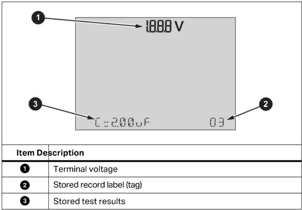
When a voltage is present at the terminals, that voltage is always shown on the top-center of the display, regardless of whether that voltage is sourced by the Tester or is from the circuit under test. See Table7.
Table 7. View Stored Results
-
Push ◀ or ▶ to step through the stored locations.
-
Stop at the location you want to view.
-
Push ▲ or ▼ to view the stored test data for a specific test. Test data appears on the alphanumeric text display and on the LCD.
Delete Test Results Stored in Memory (1537 only)
You can delete a selected test result or delete all stored test results.
To delete a selected test result:
- Push MEM. ENTER to view stored records.
- Push ◀▶ to select Record.
- With the record selected, push message: DELETE?
- Push MEM ENTER to delete the current record or push TIMER CANCEL to cancel.
To delete all test results:
- Push MEM. ENTER to view stored records.
- Push DELETE >2 seconds. The displays shows the blinking message: DELETE ALL?
- Push MEM ENTER to delete all records or push TIMER CANCEL to cancel.
V ac / V dc / Resistance (1537 only)
The 1537 includes DMM functions for V ac / V dc and resistance measurements.
To do a V ac / V dc or resistance test:
- Turn on the Tester.
- Push / to select the V ac / V dc or resistance function.
- Insert the test leads into the correct terminals. See Table 8.
- Connect the test leads to the circuit under test.
The test result appears on the Tester when the test is complete.
Note
The Tester does not support test result records for the V ac / V dc / Resistance measurements.
The Tester alarm beeps if the resistance measurement is ≤30 .
Table 8. Connections for V ac / V dc / Resistance Tests
| Item Description | |
| ① | V ac / V dc / Resistance |
| ② | COM |
1537 PC Software
Fluke provides software that lets you download test results from the 1537 Tester through the USB port.
Before you can download stored test data from the Tester, you must download the appropriate software from the Fluke website to your PC. After the download completes, follow the software prompts to install the software.
• Install the software drivers on the Windows PC before you use the USB cable.
- Do not use the test functions during communication with the PC.
- Verify that the download is successful before deleting the stored test results on the Tester.
- You can use the Fluke 1537 PC Software to clear results data stored in the Tester from the PC.
For complete information about how to use the software, see the Help module in the software.
Maintenance
There are no user-replaceable parts inside the Tester.
Warning
To prevent possible electric shock or personal injury:
- Do not repair or service the Product beyond what is described in this manual.
- Have an approved technician repair the Product.
Cleaning
Periodically wipe the case with a damp cloth and mild detergent. Do not use abrasives or solvents to clean the Tester.
Battery Replacement
To replace the batteries:
- Turn off the Product and remove all test leads.
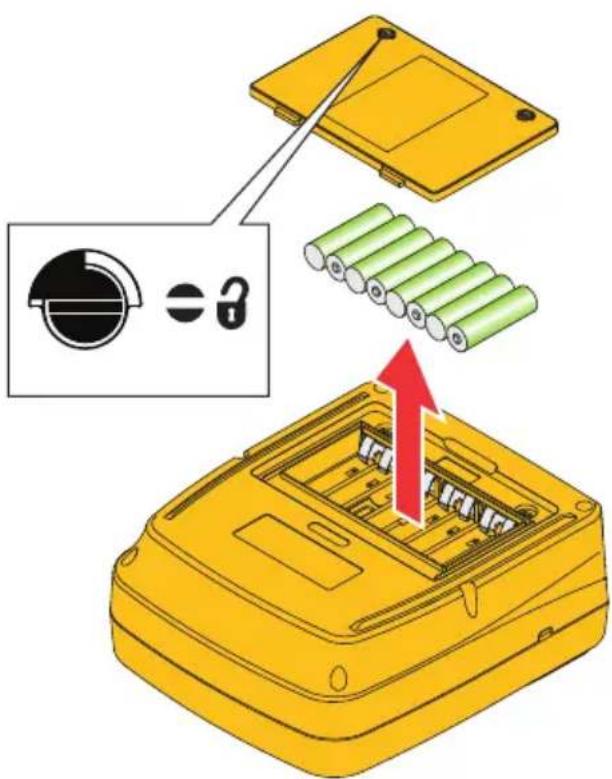
- Turn the battery-door latch until the unlock symbol (☐) aligns with the slot. See Figure 4.
- Lift off the battery door.
- Remove the AA batteries and replace with new batteries. Use the correct battery orientation.
- Install the battery door.
- Turn the battery-door latch until the slot is vertical to the unlock symbol (3).
Figure 4. Battery Replacement
Parts and Accessories
Table 9 is a list of the replaceable parts available for the Tester. Table 10 is a list of the accessories available for use with the Tester.
Table 9. Replacement Parts
| 1 2 3 4 5 | ||
| Item Description Part No. | ||
| ① | Insulation Tester: 1535/CN 4877761 | |
| Insulation Tester: 1537/CN 4877777 | ||
| Insulation Tester: 1535 5304189 | ||
| Insulation Tester: 1537 5304192 | ||
| ② | Test Lead set, 5 kV Banana Plug, Red/Black/Green 3403917 | |
| Test Probe, Banana Jack, 4 mm Tip, Red 2099044 | ||
| Test Probe, Banana Jack, 4 mm Tip, Black 2427138 | ||
| Alligator Clip – Red 2041727 | ||
| Alligator Clip – Black 2041730 | ||
| Alligator Clip – Green 2068133 | ||
| ③ | Soft Carrying Case 4862393 | |
| ④ | USB Cable (1537 only) 4499448 | |
| ⑤ | Quick Reference Card | 5304200 |
Table 10. Accessories
| Accessory Part No. | |
| 10 kV Clamp (Red/Black/Green) 4103525 |
Table 11. Number of Insulation Resistance Measurements
| Un (V) | R_load ( ) | Number of Measurements |
| 250 V 250 k 6500 | ||
| 500 V 500 k 3800 | ||
| 1000 V 1 M 2200 | ||
| 2500 V 2.5 M 1300 |
General Specifications
For a list of specifications for 1535/1537, please refer to the 1535/1537 Insulation Tester Quick Reference Guide, PN 5304200.
Electrical Specifications
The Tester's accuracy is specified for 1 year after calibration at operating temperatures of 10^ to 30^ . For operating temperatures outside the range (-10^ to +10^ and +30^ to +50^) , add ± 0.25% per ^ for 5% bands and add ± 1% per ^ for 20% bands.
Table 12. Insulation Resistance Measurement
| Test Voltage Range Resolution Accuracy | |||
| 250 V | <200 kΩ | unspecified | unspecified |
| 200 kΩ to 500 kΩ | 1 kΩ | 5 % | |
| 0.50 MΩ to 5.00 MΩ | 10 kΩ | 5 % | |
| 5.0 MΩ to 50.0 MΩ | 100 kΩ | 5 % | |
| 50 MΩ to 500 MΩ | 1 MΩ | 5 % | |
| 0.50 GΩ to 5.00 GΩ | 10 MΩ | 5 % | |
| 5.0 GΩ to 50.0 GΩ | 500 MΩ | 20 % | |
| >50 GΩ | unspecified | unspecified | |
| Test Voltage | Range | Resolution | Accuracy |
| 500 V | <200 kΩ unspecified unspecified | ||
| 200 kΩ to 500 kΩ | 1 kΩ | 5 % | |
| 0.50 MΩ to 5.00 MΩ | 10 kΩ | 5 % | |
| 5.0 MΩ to 50.0 MΩ | 100 kΩ | 5 % | |
| 50 MΩ to 500 MΩ | 1 MΩ | 5 % | |
| 0.50 GΩ to 5.00 GΩ | 10 MΩ | 5 % | |
| 5.0 GΩ to 10.0 GΩ | 100 MΩ | 5 % | |
| 10.0 GΩ to 50.0 GΩ | 500 MΩ | 20 % | |
| 50 GΩ to 100 GΩ | 5 GΩ | 20 % | |
| >100 GΩ | unspecified | unspecified | |
| 1000 V | <200 kΩ unspecified unspecified | ||
| 200 kΩ to 500 kΩ | 1 kΩ | 5 % | |
| 0.50 MΩ to 5.00 MΩ | 10 kΩ | 5 % | |
| 5.0 MΩ to 50.0 MΩ | 100 kΩ | 5 % | |
| 50 MΩ to 200 MΩ | 1 MΩ | 5 % | |
| 0.50 GΩ to 5.00 GΩ | 10 MΩ 5 % | ||
| 5.0 GΩ to 20.0 GΩ | 100 MΩ | 5 % | |
| 20.0 GΩ to 50.0 GΩ | 500 MΩ | 20 % | |
| 50 GΩ to 200 GΩ | 5 GΩ | 20 % | |
| >200 GΩ | unspecified | unspecified | |
| 2500 V | <200 kΩ unspecified unspecified | ||
| 200 kΩ to 500 kΩ | 1 kΩ | 5 % | |
| 0.50 MΩ to 5.00 MΩ | 10 kΩ | 5 % | |
| 5.0 MΩ to 50.0 MΩ | 100 kΩ | 5 % | |
| 50 MΩ to 500 MΩ | 1 MΩ | 5 % | |
| 0.50 GΩ to 5.00 GΩ | 10 MΩ | 5 % | |
| 5.0 GΩ to 50.0 GΩ | 100 MΩ | 5 % | |
| 50 GΩ to 500 GΩ | 5 GΩ | 20 % | |
| >500 GΩ unspecified unspecified | |||
| Bar graph range: 0 Ω to 1 TΩInsulation test voltage accuracy: -0 %, +10 % at 1 mA load currentCharging rate for capacitive load: 5 s/μFDischarge rate for capacitive load: 1.5 s/μF | |||
| Range | Accuracy | |
| Leakage Current Measurement | 1 nA to 2 mA | ±(20 % + 2 nA) |
| Capacitive Measurement | 0.01 μF to 2.00 μF | ±(15 % of reading + 0.03 μF) |
| Insulation Resistance Test Voltage | 250 V to 2500 V | ±(3 % + 3 V) |
| Range Resolution | ||
| Timer 0 to 99 | minutes | Setting: 1 minuteIndication: 1 second |
| Warning Range | |
| Live circuit warning | >30 V |
| Short circuit current | |
| 1535 >2 mA | |
| 1537 >5 mA | |
Table 13. V ac / V dc / Resistance Measurement (1537 Only)
| Function Range Resolution | Accuracy ±(% reading + Digits) | ||
| V ac 0 V to 6 | 00.0 V 0.1 V | ±(2 % +10)(45 Hz to 500 Hz) | |
| V dc 0 V to 6 | 00.0 V 0.1 V ±(2 % +10) | ||
| Resistance | 0 Ω to 600.0 Ω | 0.1 Ω | ±(2 % +10) |
| 600 Ω to 6000 Ω | 1 Ω | ||
| 6.00 kΩ to 60.00 kΩ | 10 Ω | ||
Table 14. Operating Ranges and Uncertainties per EN 61557
| Function | Display Range | EN 61557 Measurement Range Operating Uncertainty ±(% reading + Digits) | Nominal Values |
| V EN 61557-1[1] | 0 V ac to 600 V ac 45 Hz to 500 Hz | 0 V ac to 600 V ac ±(2 % +10 digits) | UN = 230/400 V ac f = 50/60 Hz |
| RISO EN 61557-2 | 0 kΩ to 500 GΩ | 200 kΩ to 500 GΩ ±20 % | UN = 250 / 500 / 1000 / 2500 V dc IN = 1.0 mA |
| [1] 1537 only | |||
Table 15. Operating Uncertainties per EN 61557
| Parameter Specification Typical | Max[1] | ||
| Intrinsic uncertainty | IEC 61557-2A, Reference conditions | 1.63 % 3.68 % | |
| Position | IEC 61557-2E1, Reference Conditions ±90 ° | 2.29 % 5.00 % | |
| Supply Voltage | IEC 61557-2E2, At low battery voltage stated by manufacture | 2.80 % 6.09 % | |
| Temperature | IEC 61557-2E3, 0 °C and 35 °C | 3.36 % 9.83 % | |
| Operating Uncertainty | IEC 61557-2B, ≤30 % | 7.30 % 18 | 17 % |
| [1] Confidence level: 95 % | |||
Principle of Measurement and Resistance
The Tester uses these formulas to measure insulation parameters and display the results:
| Ohm's Law | R = |
| Capacitance(Charge) | C = |
| PI(Polarization Index) | PI = _ 10R_ 1 |
| DAR(Dielectric Absorption Ratio) | DAR_[CN] = _ 1R_15s DAR = _ 1R_30s |
| DD(Dielectric Discharge) | DD = × C I = current after 1-minute dischargeV = voltage at moment before dischargeC = measured object capacitor |
- Table of Contents
- Introduction
- The Tester features:
- Contact Fluke
- Safety Information
- Warning
- Symbols
- Unpack the Tester
- The Tester
- Pushbuttons
- Tester On/Off
- Caution
- Display
- ⚠ Warning
- Guard Terminal Use
- Note
- Test Circuit Connections
- Before an Insulation Test
- Preset Test Voltage Selection
- Program a Test Voltage (1537 only)
- Select a Ramp or Steady-State Test (1537 only)
- Set a Timed Test (1537 only)
- Polarization Index (PI)
- Dielectric Discharge (1537 only)
- Dielectric Absorption Ratio
- Insulation Test
- ⚠️ Warning
- Store Test Results (1537 only)
- View Test Results Stored in Memory (1537 only)
- Delete Test Results Stored in Memory (1537 only)
- V ac / V dc / Resistance (1537 only)
- PC Software
- Maintenance
- Cleaning
- Battery Replacement
- Parts and Accessories
- General Specifications
- Electrical Specifications
- Principle of Measurement and Resistance
Brand : FLUKE
Model : 1537
Category : Measurement