
374 - Measurement FLUKE - Free user manual and instructions
Find the device manual for free 374 FLUKE in PDF.


| Product Type | Clamp Meter |
| AC Current Range (Jaw) | 0 A to 600.0 A |
| DC Current Range | 0 A to 600.0 A |
| AC Voltage Range | 0 V to 600.0 V |
| DC Voltage Range | 0 V to 600.0 V |
| Resistance Range | 0 Ω to 6000 Ω |
| Capacitance Range | 0 μF to 1000 μF |
| Inrush Current Measurement | Yes |
| True RMS AC Measurements | Yes |
| Jaw Opening | 34 mm |
| Display | Digital LCD |
| Auto Power Off | Yes |
| Low Battery Indicator | Yes |
| Power Supply | 2 AA batteries (NEDA 15A, IEC LR6) |
| Dimensions (L x W x H) | 246 mm x 83 mm x 43 mm |
| Weight | 388 g |
| Operating Temperature | -10 °C to +50 °C |
| Storage Temperature | -40 °C to +60 °C |
| Safety Rating | CAT III 1000 V, CAT IV 600 V |
| Warranty | 3 years |
| Cleaning | Use a damp cloth with mild detergent; no abrasives |
| Accessories Included | Test leads, batteries, manual |
Frequently Asked Questions - 374 FLUKE
User questions about 374 FLUKE
0 question about this device. Answer the ones you know or ask your own.
Ask a new question about this device
Download the instructions for your Measurement in PDF format for free! Find your manual 374 - FLUKE and take your electronic device back in hand. On this page are published all the documents necessary for the use of your device. 374 by FLUKE.
USER MANUAL 374 FLUKE
© 2010 Fluke Corporation. All rights reserved. Printed in China. Specifications are subject to change without notice.
All product names are trademarks of their respective companies.
LIMITED WARRANTY AND LIMITATION OF LIABILITY
This Fluke product will be free from defects in material and workmanship for three years from the date of purchase. This warranty does not cover fuses, disposable batteries, or damage from accident, neglect, misuse, alteration, contamination, or abnormal conditions of operation or handling. Resellers are not authorized to extend any other warranty on Fluke's behalf. To obtain service during the warranty period, contact your nearest Fluke authorized service center to obtain return authorization information, then send the product to that Service Center with a description of the problem.
THIS WARRANTY IS YOUR ONLY REMEDY. NO OTHER WARRANTIES, SUCH AS FITNESS FOR A PARTICULAR PURPOSE, ARE EXPRESSED OR IMPLIED. FLUKE IS NOT LIABLE FOR ANY SPECIAL, INDIRECT, INCIDENTAL OR
CONSEQUENTIAL DAMAGES OR LOSSES, ARISING FROM ANY CAUSE OR THEORY. Since some states or countries do not allow the exclusion or limitation of an implied warranty or of incidental or consequential damages, this limitation of liability may not apply to you.
Fluke Corporation
P.O. Box 9090
Everett, WA 98206-9090
U.S.A.
Fluke Europe B.V.
P.O. Box 1186
5602 BD Eindhoven
The Netherlands
Table of Contents
Title
Introduction....
How to Contact Fluke 2
Safety Information .... 3
The Meter 9
Specifications 19
Electrical Specifications.... 19
Mechanical Specifications 26
Environmental Specifications 27
374, 375, 376
Users Manual
Introduction
⚠ Warning
Read "Safety Information" before you use the Meter.
The Fluke 374, 375, and 376 (the Meter) measure true-rms ac current and voltage, dc current and voltage, inrush current, resistance, and capacitance. The 375 and 376 also measure frequency and dc millivolts. The detachable iFlex (Flexible Current Probe) that is included with the 376 (optional with the 374 and 375) expands the measurement range to 2500 A ac. The Flexible Current Probe provides increased display flexibility and allows measurements of awkward sized conductors and improved wire access. The illustrations in this manual show the 376.
374, 375, 376
Users Manual
How to Contact Fluke
To contact Fluke, call one of the following telephone numbers:
• Technical Support USA: 1-800-44-FLUKE (1-800-443-5853)
• Calibration/Repair USA: 1-888-99-FLUKE (1-888-993-5853)
• Canada: 1-800-36-FLUKE (1-800-363-5853)
• Europe: +31 402-675-200
• Japan: +81-3-3434-0181
• Singapore: +65-738-5655
• Anywhere in the world: +1-425-446-5500
Or, visit Fluke's website at www.fluke.com.
To register your product, visit http://register.fluke.com.
To see, print, or download the latest manual supplement, visit http://us.fluke.com/usen/support/manuals.
Safety Information
A Warning identifies conditions and actions that pose hazard(s) to the user. A Caution identifies conditions and procedures that could cause Meter damage, equipment under test damage, or permanent loss of data.
Symbols used on the Meter and in this manual are explained in Table 1.
⚠ Warning
To prevent possible electrical shock or personal injury, follow these guidelines:
- Use the Meter only as specified in this manual or the protection provided by the Meter can be compromised.
- Examine the case before you use the Meter. Look for cracks or missing plastic. Carefully look at the insulation around the connectors.
- Never measure current while the test leads are inserted into the input jacks.
• Make sure the battery door is closed and latched before operating the Meter. - Remove the test leads from the Meter before the battery door is opened.
- Examine the test leads for damaged insulation or exposed metal. Check test lead continuity. Replace damaged test leads before using the Meter.
-
Do not use the Meter if it operates incorrectly. Protection can be compromised. When in doubt, have the Meter serviced.
-
Do not use the Meter around explosive gas, vapor or in damp or wet environments.
- Use only type AA batteries, properly installed in the Meter case, to power the Meter.
- When measuring current with the Jaw, keep fingers behind the Tactile Barrier. See "The Meter" ①.
- To avoid false readings that can lead to electrical shock and injury, replace the batteries as soon as the low battery indicator ( +7 ) appears.
- When servicing the Meter, use only specified replacement parts.
• Have the Meter serviced only by qualified service personnel. - Be careful around voltages > 30 V ac rms, 42 V ac peak, or 60 V dc. Such voltages pose a shock hazard.
- Do not apply more than the rated voltage, as marked on the Meter, between the terminals or between any terminal and earth ground.
- When using the probes, keep fingers behind the finger guards on the probes.
- Connect the common test lead before connecting the live test lead. When disconnecting test leads, disconnect the live test lead first.
- Do not work alone so assistance can be rendered in an emergency.
- Use extreme caution when working around bare conductors or bus bars. Contact with the conductor could result in electric shock.
Clamp Safety
- Adhere to local and national safety codes. Individual protective equipment must be used to prevent shock and arc blast injury where hazardous live conductors are exposed.
- Disconnect circuit power and discharge all high-voltage capacitors before you measure resistance, continuity, or capacitance.
- For the 374 and 375, do not measure ac/dc current in circuits carrying more than 1000 V or 600 A with the Meter Jaw.
- For the 376, do not measure ac/dc current in circuits carrying more than 1000 V or 1000 A with the Meter Jaw.
- Never operate the Meter with the back cover removed or the case open.
- Do not measure ac current in circuits carrying more than 1000 V or 2500 A with the Flexible Current Probe.
- Do not apply the Flexible Current Probe around or remove from HAZARDOUS LIVE conductors.
- Do not use the flexible current sensor if the inner contrasting insulation color is showing.
• Take special care during fitting and removal of the Flexible Current Probe. De-energize the installation under test or wear suitable protective clothing.
Caution
To avoid possible damage to the Meter or to equipment under test:
• Use the proper jacks, function, and range for the measurement application.
- Clean the case and accessories with a damp cloth and mild detergent only. Do not use abrasives or solvents.
Table 1. Symbols
| Symbol | Meaning | Symbol | |
| ~ AC | (Alternating Current) | ⊥ | Earth ground |
| --- DC | (Direct Current) | Do not dispose of this product as unsorted municipal waste. Go to Fluke's website for recycling information. | |
| ⚠ Hazardous voltage CE | Conforms to European Union directives. | ||
Clamp
Safety
| Symbol | Meaning | Symbol | |
 | Risk of Danger. Important information. See Manual. |  | Conforms to relevant North American Safety Standards. |
 | Battery. Low battery when shown on display. |  | Double insulated |
 | Examined and licensed by TÜV Product Services. |  | Conforms to relevant Australian standards. |
 | Do not apply to or remove from HAZARDOUS LIVE conductors. |  | Application around and removal from HAZARDOUS LIVE conductors is permitted. |
Me:
| Symbol | Meaning | Symbol | |
| CAT III | IEC Measurement Category IIICAT III equipment has protection against transients in equipment in fixed-equipment installations, such as distribution panels, feeders and short branch circuits, and lighting systems in large buildings. | CAT IV | IEC Measurement Category IVCAT IV equipment has protection against transients from the primary supply level, such as an electricity Meter or an overhead or underground utility service. |
Meanin
Note
The Measurement Category (CAT) and voltage rating of any combination of test probe, test probe accessory, current clamp accessory, and the Meter is the LOWEST rating of any individual component.
The Meter
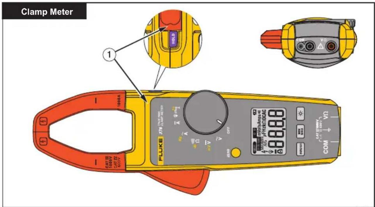
fig01.eps
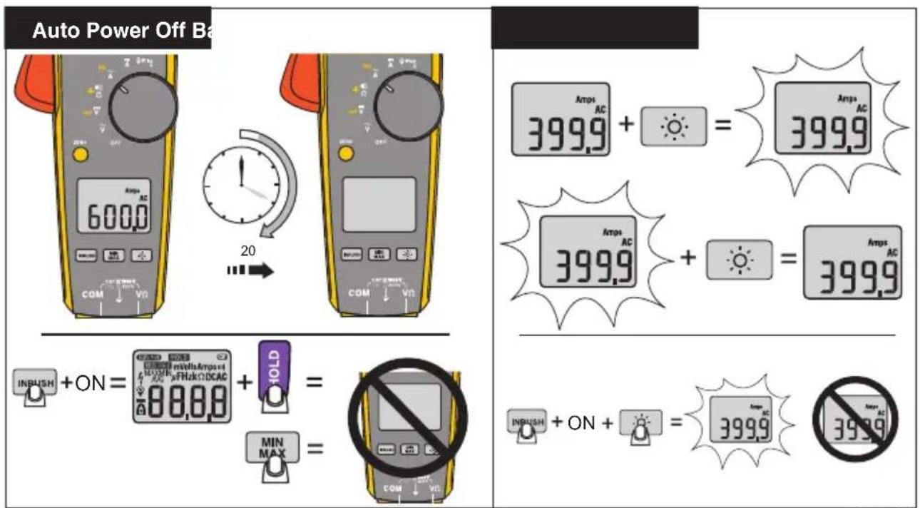
fig02_3.eps
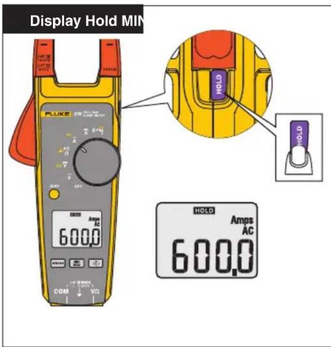
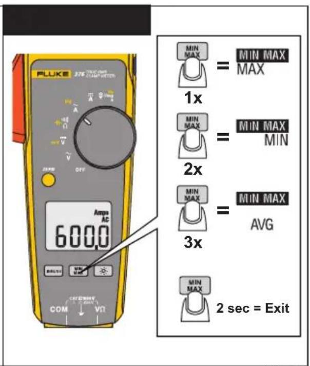
fig04_5.eps

Flexible Current Probe
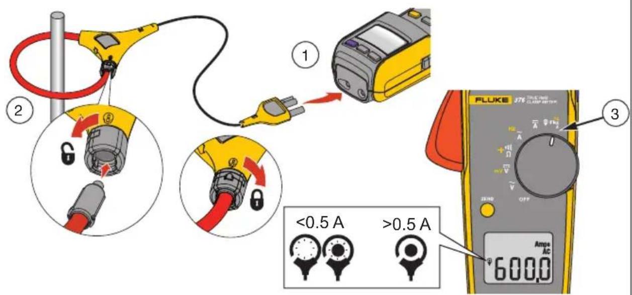
fig06.eps
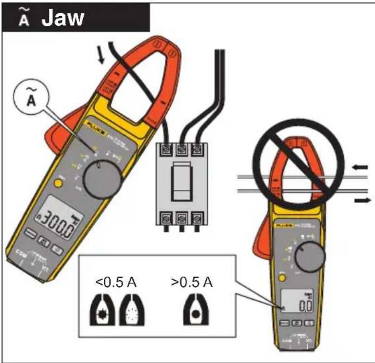
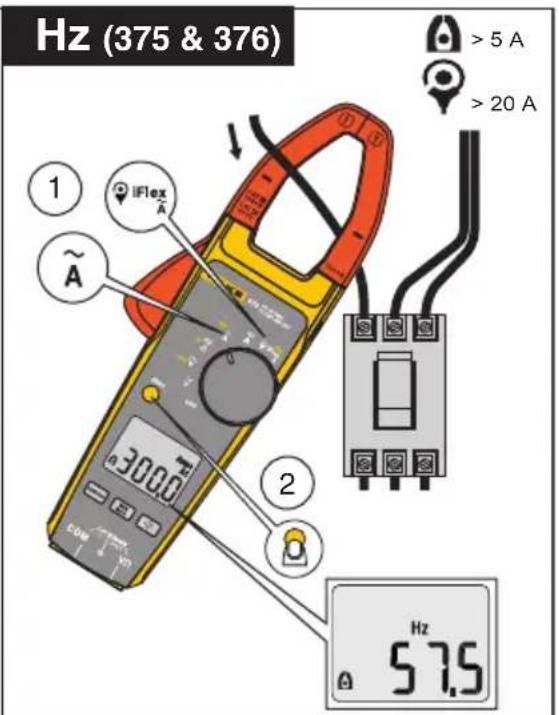
Fig07.eps
374, 375, 376
Users Manual
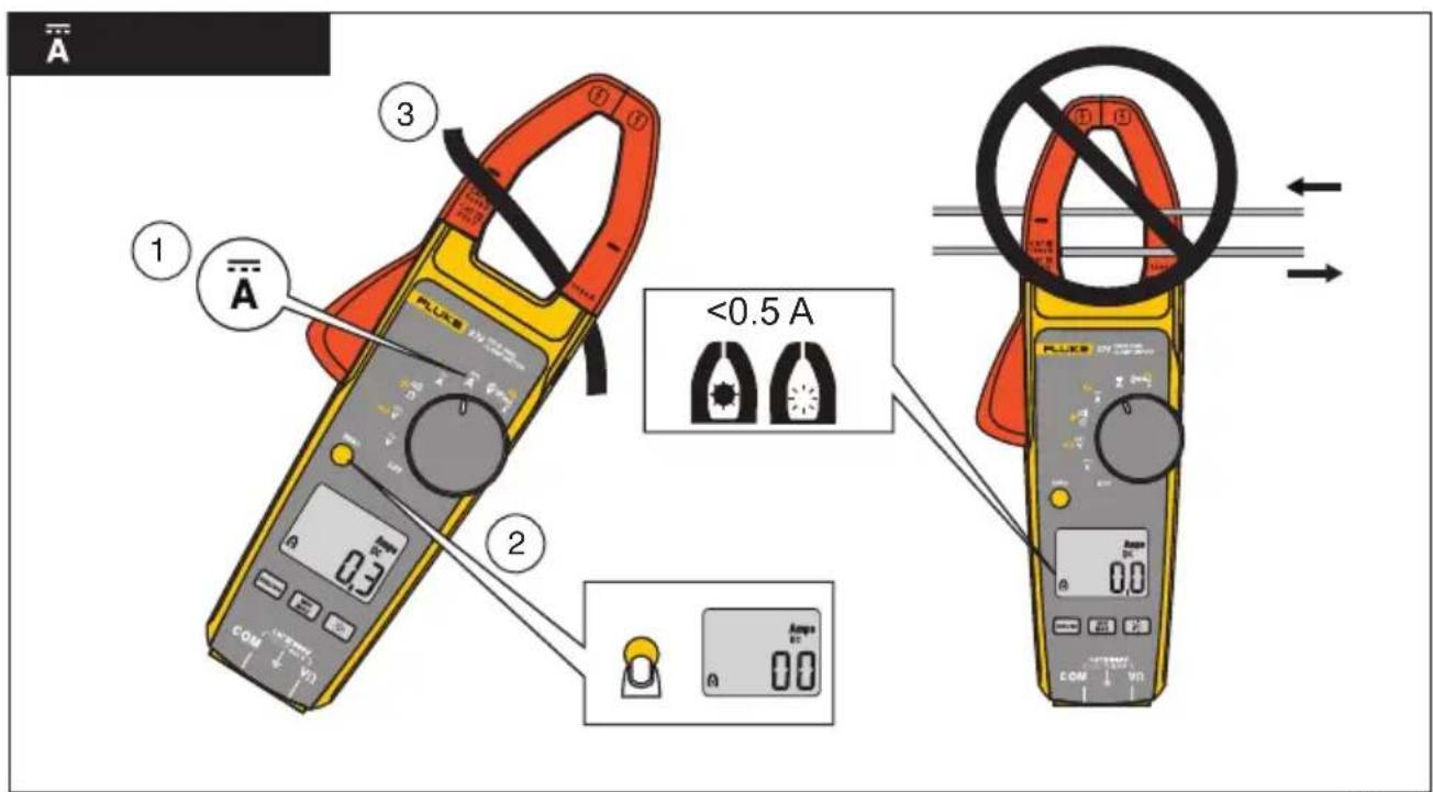
Fig08.eps
The Meter
Clamp
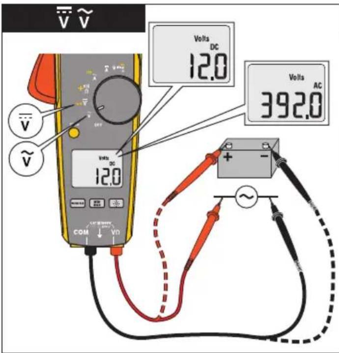
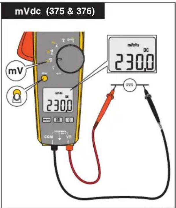
fig09_10.eps
Ω
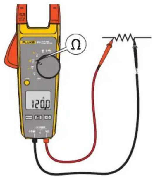
1111)
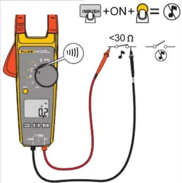
Fig15.eps
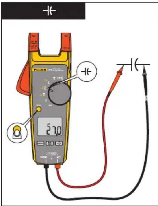
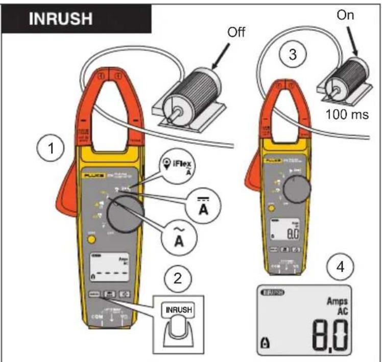
fig13_14.eps
374, 375, 376
Users Manual
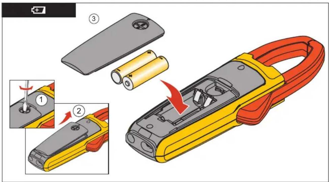
fig11_12.eps
Specifications
Electrical Specifications
AC Current via Jaw
Range
374 and 375 600.0 A
376....999.9 A
Resolution 0.1 A
Accuracy ....2 % ± 5 digits (10-100 Hz)
2.5 %
Crest Factor (50/60 Hz) ....3 @ 500 A (375 and 376 only)
2.5 @ 600 A
1.42 @1000 A (376 only)
Add 2 % for C.F. > 2
374, 375, 376
Users Manual
AC Current via Flexible Current Probe
Range 2500 A
Resolution
374 and 375 0.1 A (≤ 600 A)
1 A ( ≤ 2500 A)
376 0.1 A (≤ 999.9 A)
1 A ( ≤ 2500 A)
Accuracy ....3 % ±5 digits (5 – 500 Hz)
Crest Factor (50/60Hz) ......3.0 at 1100 A (375 and 376 only)
2.5 at 1400 A
1.42 at 2500 A
Add 2 % for C.F. > 2
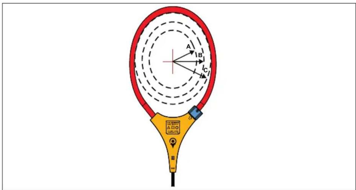
Position Sensitivity
ghn12.eps
Figure 1. Position Sensitivity
| Distance from Optimum | i2500-10 Flex i2500-18 Flex Error | |
| A 0.5 in (12.7 mm) | 1.4 in (35.6 mm) ± 0.5 % | |
| B 0.8 in (20.3 mm) | 2.0 in (50.8 mm) ± 1.0 % | |
| C 1.4 in (35.6 mm) | 2.5 in (63.5 mm) ± 2.0 % | |
| Measurement uncertainty assumes centralized primary conductor at optimum position, no external electrical or magnetic field, and within operating temperature range. | ||
DC Current
Range
374 and 375 600.0 A
376....999.9 A
Resolution....0.1 A
Accuracy 2% ± 5 digits
AC Voltage
Range
Specifications
Clamp
374 and 375 600.0 V
376 1000 V
Resolution
374 and 375 0.1 V
376 0.1 V (≤ 600.0 V)
1 V ( ≤ 1000 V)
Accuracy 1.5 % ± 5 digits (20 – 500 Hz)
DC Voltage
Range
374 and 375 600.0 V
376 1000 V
374, 375, 376
Users Manual
Resolution
374 and 375 0.1 V
376 0.1 V (≤ 600.0 V)
1 V ( ≤ 1000 V)
Accuracy .... 1 % ± 5 digits
mV dc
Range
375 and 376....500.0 mV
Resolution....0.1 mV
Accuracy 1% ± 5 digits
Frequency via Jaw
Range
375 and 376....5.0 - 500.0 Hz
Resolution....0.1 Hz
Accuracy 0.5 % ± 5 digits
Specifications
Clamp
Trigger Level 5 – 10 Hz, ≥10 A
10 – 100 Hz, ≥5 A
100 - 500 Hz, ≥10 A
Frequency via Flexible Current Probe
Range
375 and 376 ....5.0 - 500.0 Hz
Resolution 0.1 Hz
Accuracy 0.5 % ± 5 digits
Trigger Level 5 - 20 Hz, ≥ 25 A
20 - 100 Hz, ≥ 20 A
100 - 500 Hz, ≥ 25 A
Resistance
Range
374....6000 Ω
375 and 376....60 kΩ
374, 375, 376
Users Manual
Resolution
374....0.1 Ω (≤ 600 Ω)
1 Ω (≤ 6000 Ω)
375 and 376....0.1 Ω (≤ 600 Ω)
1 Ω (≤ 6000 Ω)
10 Ω (≤ 60 kΩ)
Accuracy 1% ± 5 digits
Capacitance
Range 1000 μF
Resolution....0.1 μF (≤ 100 μF)
1 F(≤ 1000 F)
Accuracy 1% ± 4 digits
Mechanical Specifications
Size (L x W x H) 246 mm x 83 m x 43 mm
Weight....388 g
Jaw Opening....34 mm
Specifications
Clamp
Flexible Current Probe Diameter ....7.5 mm
Flexible Current Probe Cable Length
(head to electronics connector)......1.8 m
Environmental Specifications
Operating Temperature....-10 °C - +50 °C
Storage Temp ....-40 °C - +60 °C
Operating Humidity ....Non condensing (< 10 - °C)
$$ \leq 90 \% \mathrm{RH} (\text { at } 10 ^ {\circ} \mathrm{C} - 30 ^ {\circ} \mathrm{C}) $$
$$ \leq 75 \% \mathrm{RH} (\text { at } 30 ^ {\circ} \mathrm{C} - 40 ^ {\circ} \mathrm{C}) $$
$$ \leq 45 \% \mathrm{RH} (\text { at } 40 ^ {\circ} \mathrm{C} - 50 ^ {\circ} \mathrm{C}) $$
Operating Altitude 3000 meters
Storage Altitude 12,000 meters
EMC ......EN 61326-1:2006
Temperature Coefficients....Add 0.1 x specified accuracy for each degree C above
28 °C or below 18 °C
374, 375, 376
Users Manual
Safety Specifications
Safety Compliance....CAN/CSA-C22.2 No. 61010-1-04
ANSI/UL 61010-1:2004
ANSI/ISA-61010-1 (82.02.01
EN/IEC 61010-1:2001 to
1000V Measurement Category (CAT) III
600V Measurement Category (CAT) IV
Pollution Degree
EN/IEC 61010-2-032:2002
EN/IEC 61010-031:2002+A1
CE
Agency Approvals.... C US, N10140, TUV
Batteries....2 AA, NEDA 15A, IEC LR6
- LIMITED WARRANTY AND LIMITATION OF LIABILITY
- Table of Contents
- Title
- Introduction
- Read "Safety Information" before you use the Meter.
- How to Contact Fluke
- Safety Information
- ⚠ Warning
- Clamp Safety
- Caution
- Clamp
- Safety
- The Meter
- Specifications
- Electrical Specifications
- 374, 375, 376
- Users Manual
- AC Current via Flexible Current Probe
- Position Sensitivity
- DC Current
- Resolution
- DC Voltage
- Range
- Frequency via Jaw
- Capacitance
- Mechanical Specifications
- Environmental Specifications
Brand : FLUKE
Model : 374
Category : Measurement