
MEG-4000 - Uncategorized MEGASAT - Free user manual and instructions
Find the device manual for free MEG-4000 MEGASAT in PDF.


| Brand | Megasat |
| Model | MEG-4000 |
| Product Type | SAT>IP Server |
| Number of Tuners | 4 (DVB-S) |
| Dimensions (L x W x H) | 250 x 135 x 44 mm |
| Weight | 142 g |
| Power Supply | AC 100-240V, 50/60Hz; DC 12V, 3A |
| Processor | STi7108 |
| RAM | 512 MB DDR3-1066 |
| Flash Memory | 1 MB NOR / 128 MB NAND |
| Ethernet | RJ45 10/100/1000 |
| SAT>IP Version | 1.2 compatible |
| Video/Audio Support | MPEG2 / MPEG4 TS & PS |
| LNB Protocols | Unicable, JESS, DiSEqC 1.0/1.2, USALS |
| Satellite Inputs | 4x DVB-S (F-type connectors) |
| USB Port | 1x USB 2.0 for firmware updates |
| LED Indicators | Green (power), Red (streaming) |
| Power Switch | Yes |
| Operating Temperature | 0°C to 40°C |
| Compliance | CE (EMC 2004/108/EG, LVD 2006/95/EG) |
| Compatible Clients | iOS, Android, DLNA/UPnP devices |
Frequently Asked Questions - MEG-4000 MEGASAT
User questions about MEG-4000 MEGASAT
0 question about this device. Answer the ones you know or ask your own.
Ask a new question about this device
Download the instructions for your Uncategorized in PDF format for free! Find your manual MEG-4000 - MEGASAT and take your electronic device back in hand. On this page are published all the documents necessary for the use of your device. MEG-4000 by MEGASAT.
USER MANUAL MEG-4000 MEGASAT
natural_image
White industrial heat exchanger with zigzag ventilation slots and a 'POWER STREAMING' label (no other text or symbols)SAT>IP Server 2
Bedienungsanleitung
Inhaltsverzeichnis
Twin LNB = RF1 + RF2
Tuner RF1 = Horizontal High (HH)
Tuner RF2 = Horizontal Low (HL)
Tuner RF3 - Vertical High (VH)
Tuner RF4 = Vertikal Low (VL)
Unicable (Unicable LNB or Unicable multiswitch)
Thu 4 Dec 2014 16:28:19
Software upgrade - webui
which is software image Datei (• sb)
Boschwecken
(No text)

natural_image
White electronic device with a grid-patterned ventilation grille and indicator lights (no text or symbols visible)SAT>IP Server 2
user manual
Content
Safety Instructions....03
- Introduction 04
- Connection & How to access 05
- Login / Logout 08
- System Settings 09
4.1 Network Settings 10
4.1.1 Wired 11
4.1.2 Wireless 12
4.2 LNB Settings 15
4.2.1 LNB Einstellung....16
4.2.2 Quad 17
4.2.3 Quattro 18
4.2.4 Unicable 19
4.2.5 Jess.... 20
4.2.6 DiSEqC 21
4.2.7 USALS....27
4.3 Import Settings 28
4.4 Export Settings 29
- System Status
5.1 Tuner Status 30
- Tuner
6.1 Tuner settings....32
6.2 Tuner test 34
- Software Update
7.1 USB....35
7.2 OND 42
7.3 WebUI 48
- Admin
8.1 SW Version....51
8.2 Language 51
8.3 Change Password....51
8.4 Restart....51
- Specifications 52
Safety Instructions
Please read the manual thoroughly before operating the equipment. In case of incorrect or improper handling, the warranty becomes void.
Power supply: Before start please check the correct operation voltage of the power point. The operating voltage of this device is AC 100 \~ 240V, 50/60Hz.
Overload: Do not overload a wall outlet, extension cord or adapter, neither use damaged power cord or touch it with wet hand as this may result in electric shock.
Liquid: The device shall not be exposed to dripping or splashing water, and that no objects filled with liquids, such as base, shall be placed on the apparatus.
Ventilation: Keep the slots on top of the device uncover to allow sufficient airflow to the unit. Do not put the receiver on soft furnishings or carpets. Do not expose the receiver to direct light or do not place it near a heater or in humid conditions. Do not stack other electronic equipments on top of the receiver.
Risk of ssuffocation: Do not let children play with films or other packaging components, there is a risk of suffocation.
Cleaning: Plug out the device from the wall outlet before cleaning. Clean the device by a soft cloth or mild solution of washing-up liquid (no solvents).
Connection: Disconnect the device from the mains when you connect it to satellite LNB or disconnect it from LNB. Failure would possibly cause damage to the LNB.
Location: Put the device indoor in order to avoid lightening, raining or sunlight.
Uncover: Do not remove the cover, to reduce the risk of electric shock. Contact qualified and licensed service personnel to repair the receiver, or contact your dealer.
1. Introduction
SAT>IP Server 2 allows free satellite live TV/Radio programs to be received & distributed to SAT>IP Client compliant devices like smart phones, tablet pc's and notebook pc's & other client devices over Wired/Wireless home network in both unicast/multicast mode of transmission. SAT>IP Server 2 is equipped with four satellite tuners, so users can watch 4 x different frequency simultaneously & with same frequency 8 x different users can watch simultaneously.
SAT>IP Server 2 device must be connected to same home network in which the Client devices which are connected to.
SAT-IP Server Features:
- Fully compliant with SAT>IP Specification version 1.2
• Streaming Live SD/HD TV & Radio programs to 4 compatible Clients over LAN/WLAN
• Support MPEG2/MPEG4 TS & PS over IP in both Unicast and Multicast
• Support Unicable, JESS, DiSEqC1.0, DiSEqC 1.2 and USALS - Firmware update over USB stick or online over the network
- Web UI based device configuration and management (password protected)
Supported Client devices:
• SAT IP supporting devices (IP 100, ...)
- iOS devices (iPad, iPod, iPhone), Android tablets and smart phones using Elgato applications
• DLNA/UPnP compatible PC software applications e.g.VLC Player, DVB Viewer
2. Connection & How to access
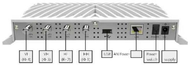
Connection with a Universal LNB (z.B. Single, Twin or Quad LNB)
Single LNB = RF1
Twin LNB = RF1 + RF2
Quad LNB = RF1 + RF2 + RF3 + RF4 (The order is not important)
Connection with a Quattro LNB
The device must be connected to the appropriate connector on the Quattro LNB, please make sure the correct ports on the LNB:
Tuner RF1 = Horizontal High (HH)
Tuner RF2 = Horizontal Low (HL)
Tuner RF3 - Vertical High (VH)
Tuner RF4 = Vertical Low (VL)
Connection with a Unicable LNB
Unicable LNB = RF1
Note that a change must be made in the web configurator. The respective settings, see page 19.
Connection with a Jess LNB
Unicable LNB = RF1
Note that a change must be made in the web configurator. The respective settings, see page 20.
Connection with a DiSEqC controlled device
Depending on the connection used, please refer to the corresponding DISEqC settings. The respective settings, refer to page 21.
Connection with a Motor (USALS)
Motor(USALS)=RF1
Note that a change must be made in the web configurator. The respective settings, see page 25.
2. Connection & How to access
Identify the IP address
Turn on the server. The server connects to the network and receives own IP address automatically. You can also assign the server in your network a static IP address with DHCP.
To access the web configurator, it is necessary the IP address to identify the device. This can be found in the following manner:
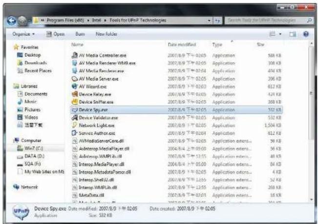
The Megasat SAT> IP Server 2 supports UPnP technology that experienced it. Users allows the IP address to identify a free UPnP tool (eg Intel Developer Tools for UPnP Technologies).
- Download the appropriate software on the PC and install it.
- Open the "Device Spy" from the Start menu.
2. Connection & How to access
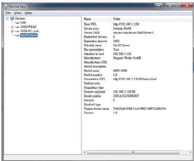
- Select in the list of "UPnP Devices" to "Megasat SAT> IP Server 2", and read the corresponding "Base URL" from (for example 192.168.2.100)
Configuration
The server can be configured with a PC that is located in the same network. The configuration is done through a web browser with which you have to log in to access the user interface of the server.
Open a web browser (Recommended: Google Chrome or Opera) and enter the server's IP address. You can find the assigned IP address in the configuration menu of the Internet router.

3. Login / Logout
Login
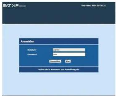
Once the browser was successfully connected to Server, then the "Login" page will be displayed. The default user name for server is "admin" and password is "admin". Enter the Password and click the "Login" button. The server page will be displayed on the screen.
We have restricted the password length to be minimum of 8 characters and maximum 16 characters.
Logout
To log out, click on "Logout" icon place at right top corner.
Select "Yes" from the confirmation to log out from the Server page.
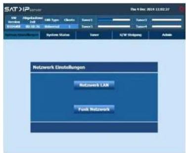
Server box supports the below network mode of interfaces.
- Wired Network
- Wireless Network
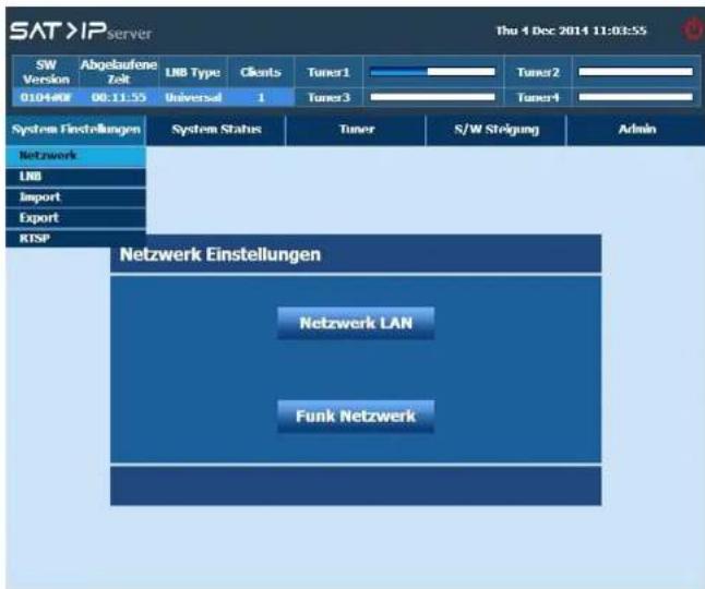
Click "System Settings->Network Settings" from the server page.
4. System Settings
Click "System Setting" from the Server page.
Topics covered under Admin are listed below:
• Network Settings
• LNB Settings
- Import Settings
- Export Settings
4.1 Network Settings
Wired Network
Server box supports the below IP mode of configurations in Wired network,
• DHCP (Managed Network)
• AUTO IP (Unmanaged network)
- Manual (User IP configuration)
Note:
- By default the Server box is in DHCP mode.
- Server box failed to find DHCP server then it will automatically move to Auto-IP mode & allocate IP address in 169.x.x range.
Wireless Network
Server box supports the below IP mode of configurations in Wireless network.
• Auto
- Manual
4. System Settings
4.1.1 Wired
By default the Server box is in DHCP mode.
Server acquires IP address from DHCP server & listed the information on the screen.
Server box failed to find DHCP server then it will automatically move to Auto-IP mode & allocate IP address in 169.x.x range.
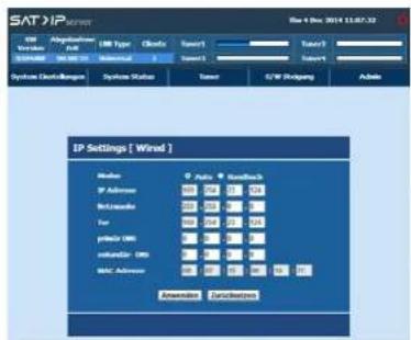
User can configure the IP settings by "Manual" mode also. In manual mode user can enter/edit the IP settings. IP configuration can be edited from this dialog.
After complete the IP configuration, click "Apply" for save.
![SAT/IP File 1 No: 2014.12.08.53 IP Abgltzum USB USB Type Class Sens1 Sens2 Sens3 System Usatzungen System Status Tener U/W Dningung Admin IP Settings [ Wired ] Mode: © Auto © Readback IP Address: 100 100 100 100 Rikksmater: 200 200 200 200 Ior: 100 100 100 100 grisie/100 unwidade/100 MAC Address: 100 100 100 100 Extension Functionality](/content/2026/05/842175/images/6fe9bae807927816b20d57cefd71c3d3639f18e46e039177d000c89349fec72d.jpg)
4. System Settings
4.1.2 Wireless
Wireless option can be configure by Auto (or) Manual.
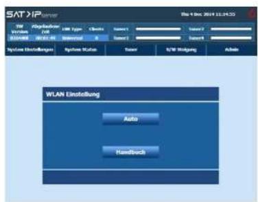
If user selects "Auto", WiFi routers which is available nearby can be discovered automatically & listed.
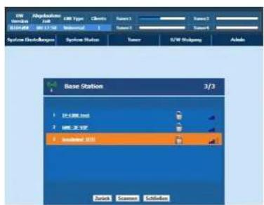
# Network name (SSID): Name of the network. Network name will be truncated with ellipsis (...) if the network name exceeds more than 15 characters.
# Signal Quality: Signal icon displayed with different colors based on the reception quality.
# Lock: Lock icon will be displayed if the connection mode is secure. Supported security modes are WPA, WPA2, WEP-64 bit, WEP-128 bit.
4. System Settings
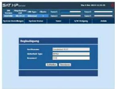
Password request screen will be displayed if user select WPA secure system available WiFi router. Using keypad user should enter the valid WPA key.
A warning pop-up is displayed if the password is invalid or the Receiver is unable to connect to the network.
In the event that the warning pop-up is displayed, pressing any key causes the network list to be re-displayed with the same network in focus.
Enter valid password and select "Connect" button; the wireless network will be connected successfully.
The Green color tick icon is displayed if WiFi Router is connected without any problem. All WiFi network settings are stored in the system memory.
![SAT/IP server S/N Abgkathion Service S/N Type Tools Server1 Server2 R03488 R03489 Manual T0347 System DisChallenger System Status Source S/N Drilling Address Base Station [Goodmind-TEST] 1/3 1 Goodmind (S/N) 2 JG-1.0M test 3 JG-3.1VSP](/content/2026/05/842175/images/973a55646452e9d17d04c395be00e43ef8593300aa2d48931585e041789e0849.jpg)
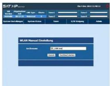
Wireless can be configured by Manually. To connect the Box to WiFi router user need to provide the Device information.
If users pressing OK key the base station will be opened. Further procedure will be same as explained for Auto mode.
4. System Settings
4.2 LNB Settings
Select the type of LNB that is connected to Satellite input of your box based on your satellite installation. Topics covered under are listed below:
Quad
Select "Quad" when a Quad LNB, Octo LNB or Universal multiswitch is connected to your Server box.
Select „Quattro” when a Quattro LNB is connected to your Server box directly.
Unicable (Unicable LNB or Unicable multiswitch)
Select "Unicable" when a Unicable switch is connected to your Server box
JESS
Select „Jess“ when a Jess switch is connected to your Server box.
DiSEqC1.2
Select "DiSEqC" when a DiSEqC1.2 motor is connected to your Server box.
USALS
Select "USALS" when a USALS motor is connected to your Server box.
How to Access?
Click „LNB Setting“ from the Server page.
4. System Settings
Satellite reception system consists of a Quad LNB. Connect the 4 outputs of the LNB to the inputs 1...4 of the Server box via suitable SAT antenna cables.
Similar to all Tuners.
- Horizontally polarised, high band 11.70-12.75 GHz ("horizontal high")
• Horizontally polarised, low band 10.70-11.70 GHz (horizontal low")
• Vertical polarised, high band 11.70-12.75 GHz (vertical high")
• Vertical polarised, low band 10.70-11.70 GHz (vertical low")
4. System Settings
4.2.3 Quattro 4.2.4 Unicable
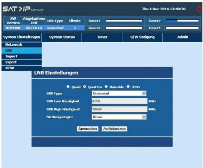
Satellite reception system consists of a Quattro LNB. Connect the 4 outputs of the Quattro LNB to the inputs 1...4 of the Server via suitable SAT antenna cables & and ensure the correct port assignment should be as follows:
- RF#4 - LNB output "horizontal high" into input 1(11.70-12.75 GHz)
- RF#3 - LNB output "horizontal low" into input 3(10.70-11.70 GHz)
• RF#2 - LNB output „vertical high“(11.70-12.75 GHz)
• RF#1 - LNB output „vertical low“ (10.70-11.70 GHz)
4. System Settings
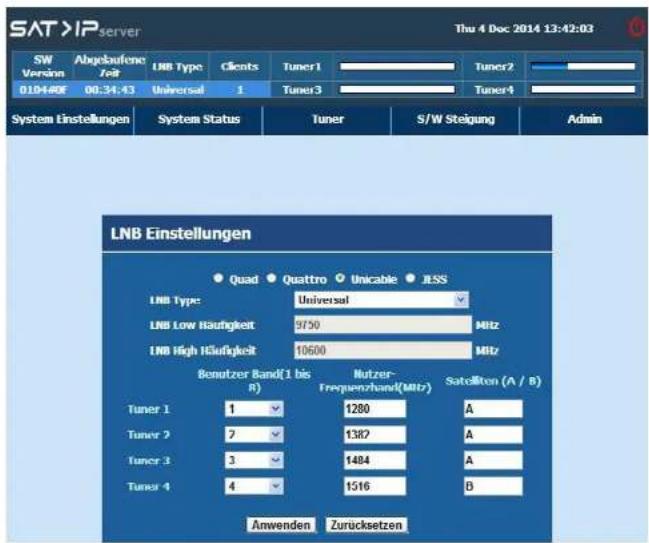
Unicable distribution is a satellite TV technology that enables delivery of broadcast programming to multiple users over a single coaxial cable.
- Unicable IF Channel have eight options: None, 1, 2, 3, 4, 5, 6, 7 & 8
- User has provided the edit option Centre frequency.
- User has provided the option to select the available Ports A or B.
4. System Settings
4.2.5 Jess 4.2.6 DiSEqC
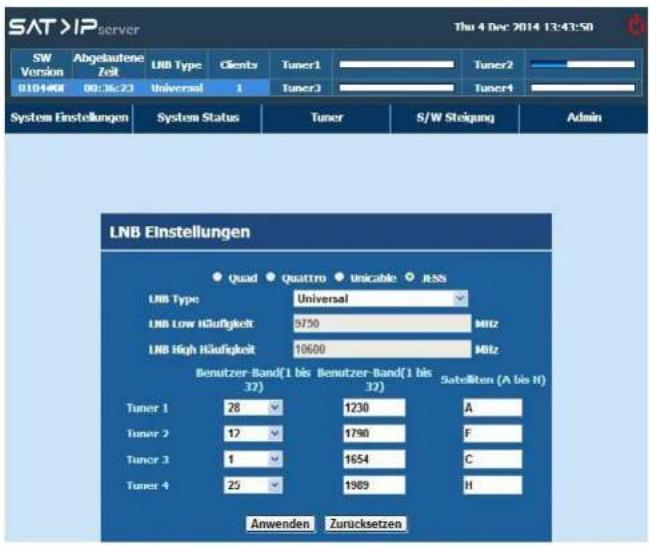
32 users can able to view the 8 different satellites via user band frequency.
4. System Settings
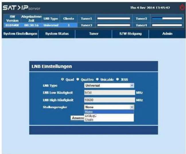
DISEqC 1.2 is used to move the motor manually. Using this option user can move the motor with the following moving controls.
- User - Step by step movement, based on user input.
• Installer - Continuous movement - Goto X - Move to the dish to user specified position
-
Advanced - Dish settings(For e.g. Dish moving limits, Reset dish position, etc.)
-
System Settings
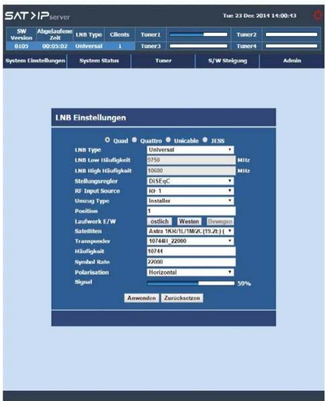
Set the Dish moving type as INSTALLER. Press Left/Right key in Drive East/West option to move the motor. Now motor will be move continuously/coarse movementJ. Motor movement will be stop when the user press again LEFT/RIGHT key.
- System Settings
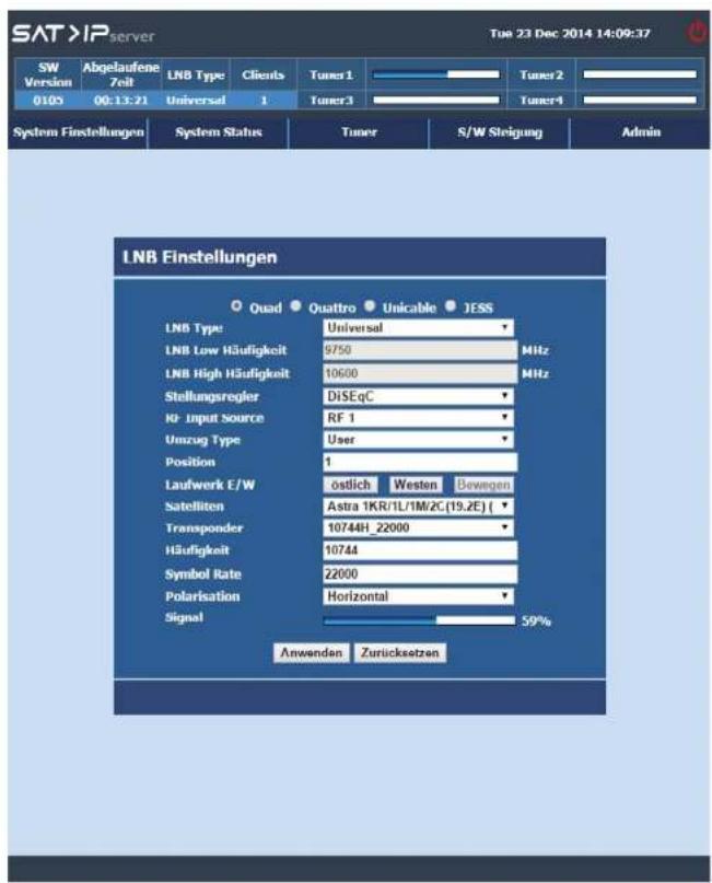
Set the Dish moving type as USER. Press Left/Right key in Drive East/West option to move the motor. Now motor will be move slowly [step by step movement].
4. System Settings
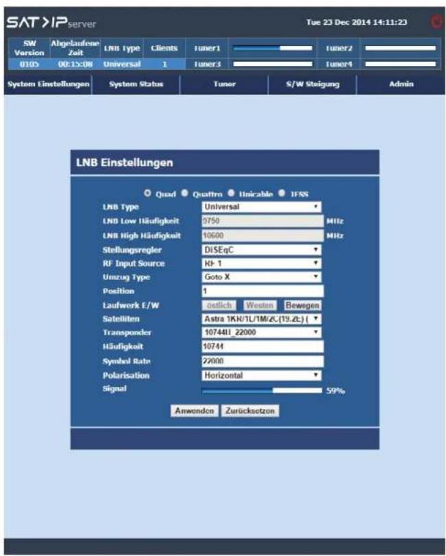
GoTo X option is used to move the motor in specified position. To perform this action, select Dish moving type as GoTo X and enter the Dish position by pressing numeric keys. Then press OK key, now dish will be move to specified dish position.
4. System Settings
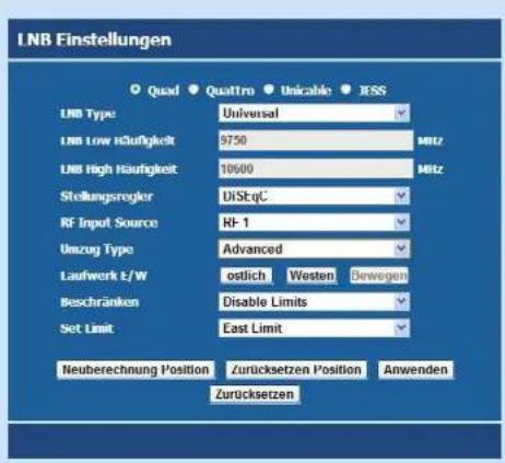
The above picture which shows the Advanced setup, through this setup user can perform the below listed Motor related settings,
- Enable / Disable limit - Enable or Disable the motor rotation to the restricted direction angle.
- Drive East / West - User can rotate the dish either Fast/West direction by pressing LEFT/RIGHT key.
- Set EAST / WEST limit - This option is only enable, when we set the „Enable limits“. Using this option, user can set the desired east / west angle. Afterward, they can't able to move the dish after that angle. If user want to move the dish after that angle, then they need to set the limit option as „Disable limits“. Recalculate Position - By pressing the RED key, user can achieve the „RECALCULATE" function.
- This Recalculate position option will replace the logical positions set by the user. If user does this operation, confirmation will be displayed. If user selects YES option, "Dish Moving" message will be displayed.
-
Reset Position - The motor position can be reset to its reference position [0 degree] by using the Reset Position option. Confirmation message will be displayed after pressing GREEN color key. If user select YES option, "Dish is Moving" message will be displayed.
-
System Settings
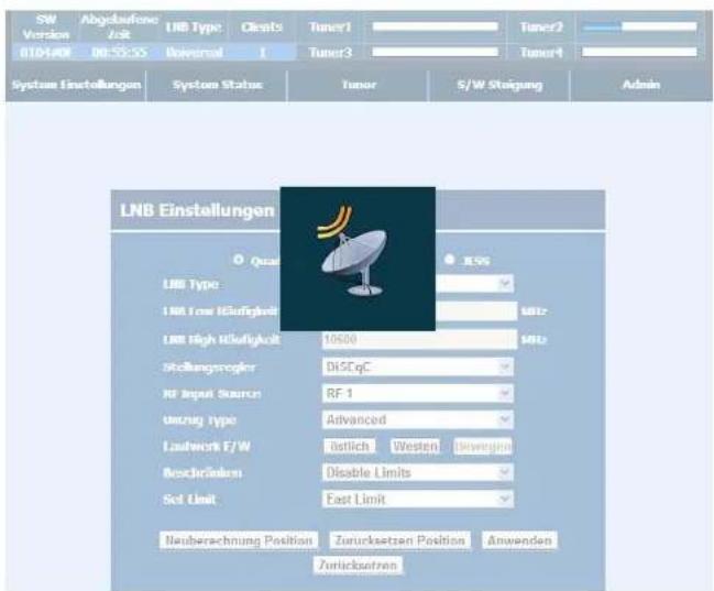
The above picture shows the Motor moving in-progress.
- System Settings
4.2.7 USALS
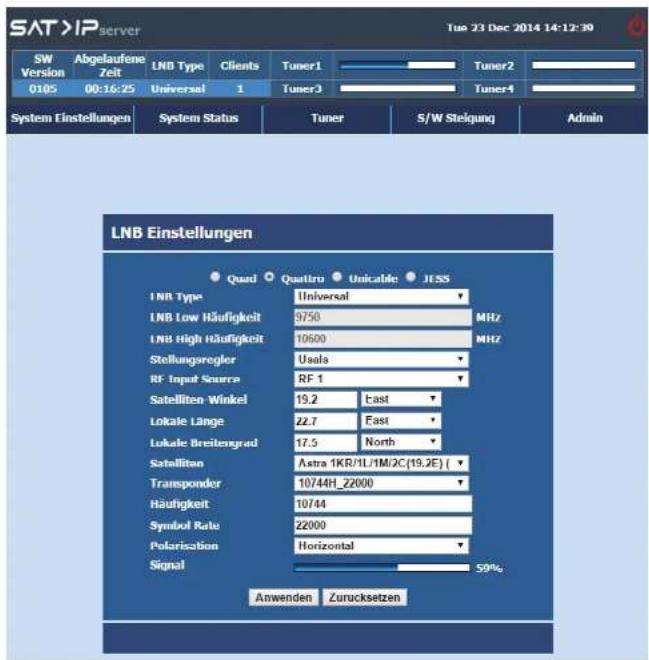
USALS means Universal Satellite Automatic Location System. This type is used to move the dish towards the satellite position automatically.
USALS is used to position the dish automatically without user stress. By giving the input of satellite angle, user latitude & longitude angle, motor will be positioned automatically to the selected satellite.
4. System Settings
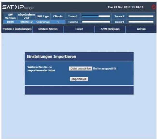
Import Settings: User can import the configuration information which was available from the receiver (can be extracted using export settings).
4. System Settings
4.4 Export Settings4.3 Import Settings
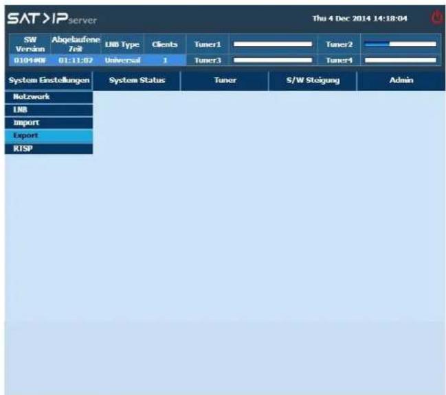
Using export settings user can retrieve the user configured details of the Server & stored it as separate XML file.
5. System Status
System status menu gives the informations about:
- Tuner details
- Tuner parameters
- Streaming details
5.1 Tuner Status
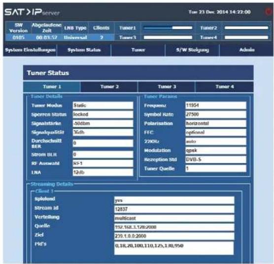
Tuner status screen gives details about;
- Tuner details
- Tuner parameters
- Streaming details
6. Tuner
Select the type of Tuner of your box based on your satellite installation. Topics covered under are listed below:
Tuner Settings
- Select "Dynamic" for Server box tuned the client requested carrier.
- Select "Static" for Server box tuned the fixed carrier where the client can only tune that carrier.
Tuner Test
- Select „Tuner Test“ to check the tuner lock sattus.
6. Tuner
6.1 Tuner Settings
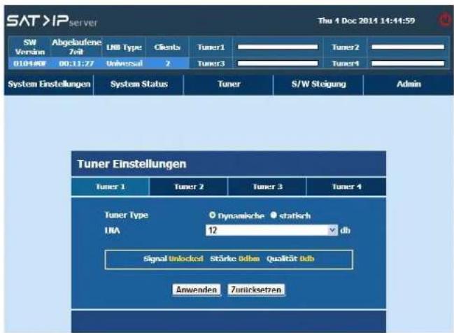
- By default the Server box is in Dynamic mode.
- Server box tuned the client requested carrier in Dynamic mode.
-
Once the Client is requested to lock the particular frequency. Then Server box tuned that carrier in Dynamic mode.
• LNA used to attenuate the signal strength and quality. -
Tuner
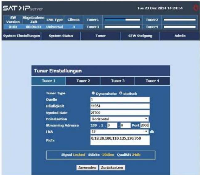
Select "Static" for configure the tuner to the particular frequency where the client can only tune that carrier.
- Source - To select DiSEqC 1.0 switch (A, B, C or D). The default value set to be 1.
• Frequency - To enter the fixed frequency. - Symbol rate - To enter the fixed symbol rate(1000 to 65000 kps).
- Polarization - To select Horizontal / Vertical.
- Streaming Address - To enter the IP address and port number for multicast. Each field values shall be 0 to 255. Port no range should be 1024 -65535.
• LNA - To attenuate the signal from 0 to 16db. - PID's - To enter (PAT, PMT, Audio, Video, Subtitle, Audio Descriptor, Teletext...) PID's. Maximum of 32 pids and no more duplication allowed.
6. Tuner
6.2 Tuner Test
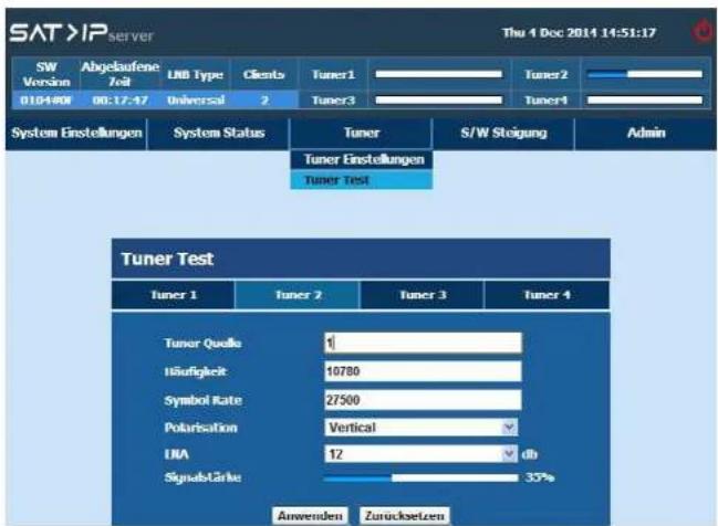
Enter the below valid parameters to check the tuner lock sattus.
- Source - To select the Tuner source
• Frequency - To enter the fixed frequency. - Symbol rate - To enter the fixed symbol rate(1000 to 65000kSps).
- Polarization - To select Horizontal / Vertical.
• LNA - To attenuate the signal from 0 to 16db.
7. Software Update
In order to support S/W upgrading, we have supported the below upgrading modes,
- S/W download via USB
• S/W download via OND
• S/W download via WEB UI
7.1 USB
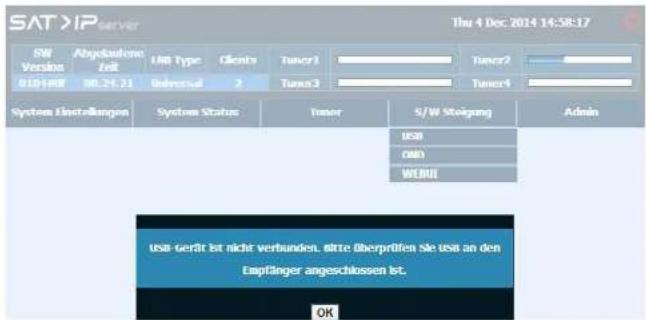
The S/W Upgrade via USB option used to download the latest software by USB memory device
Procedure for S/W Upgrade via USB:
- Format (FAT32 file format) the USB stick and create the folder name "Update"
- Copy the .usb images directly in to the folder name „Update“ and insert the USB memory device in the STB USB port.
- Select the S/W Upgrade via USB option from the menu.
Note:
If USB media is not inserted and when user select "Software Upgrade via USB" then above message will be displayed.
- Software Update
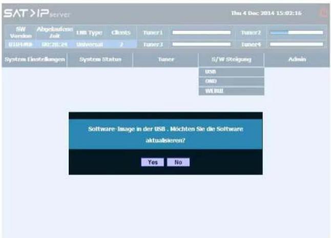
If USB media is inserted with S/W image and when user select „Software Upgrade via USB" then above message will be displayed.
- Software Update
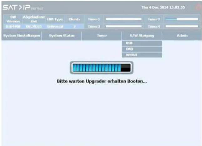
System switch to Upgrader mode when select Yes from the confirmation.
- Software Update
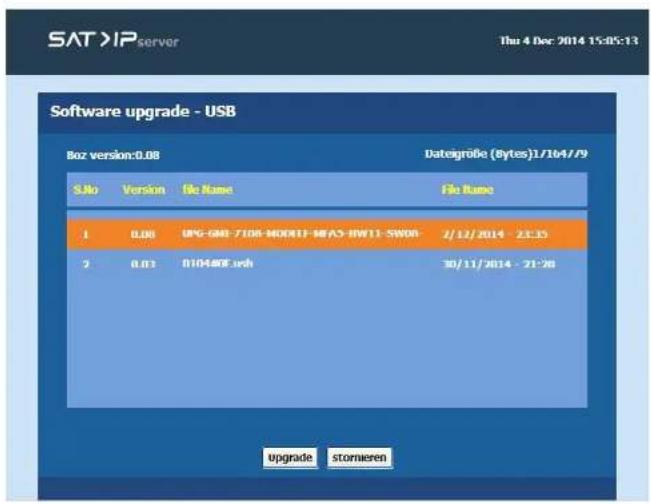
System boot the upgrader mode and if the „Update“ folder in USB contains more than one file the above screen will be displayed. User need to select the correct image. Otherwise it directly start the S/W fusing.
- Software Update
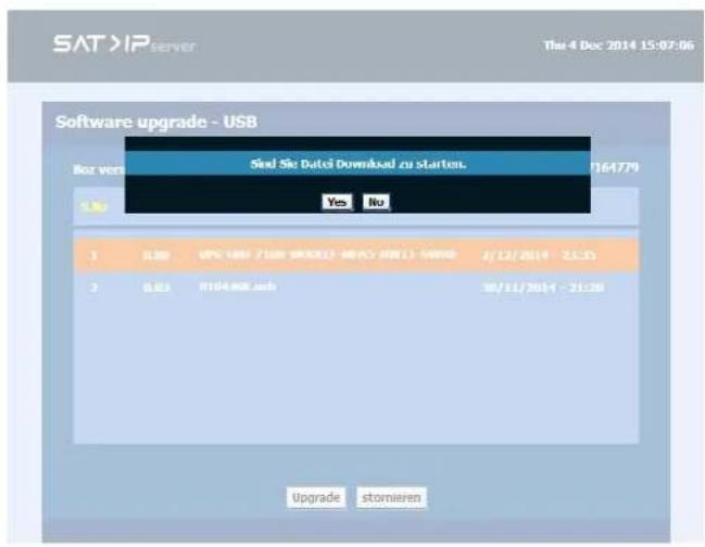
Select the correct image and press the ok key, downloading will start.
7. Software Update
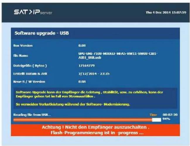
The above slide indicated downloading in-progres. Warning - Don't power off the STB during software downloading/erasing/fusing.
7. Software Update
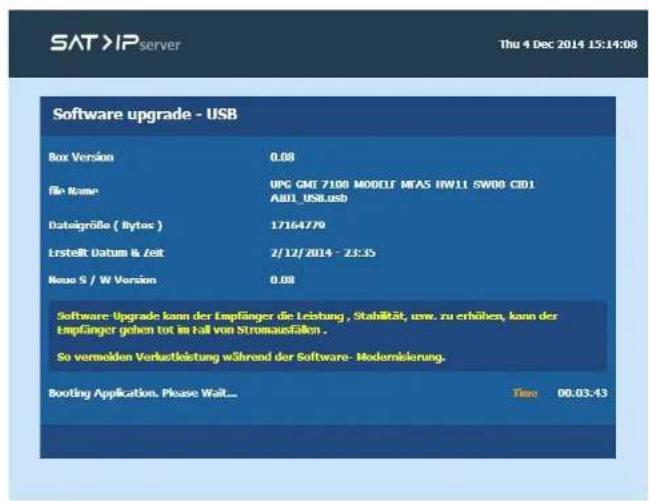
After complete the downloading, box booted with new S/W.
7. Software Update
7.2 OND
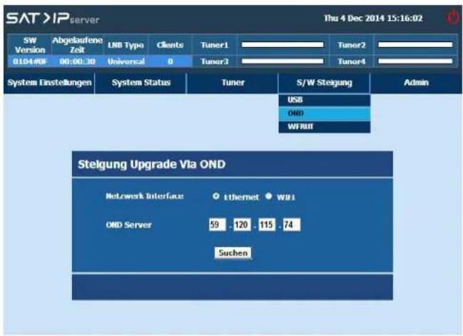
Upgrade the software from anywhere in the network world through TCP/IP mode of connection in a secure manner.
Select the Network Interface mode and enter the OND server IP address for search the S/W availability.
7. Software Update
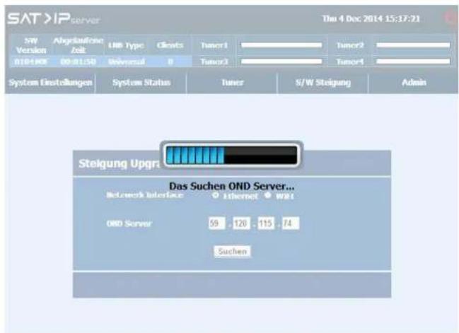
When select "Search" Button, STB will search new S/W in the Network.
- Software Update
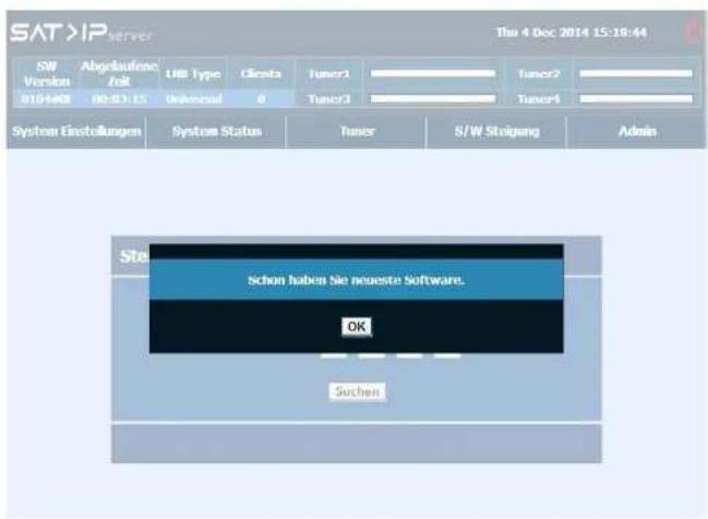
If new S/W is not available then STB shows the above message.
- Software Update
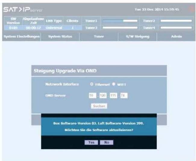
If new S/W is available then STB shows the above confirmation message.
7. Software Update
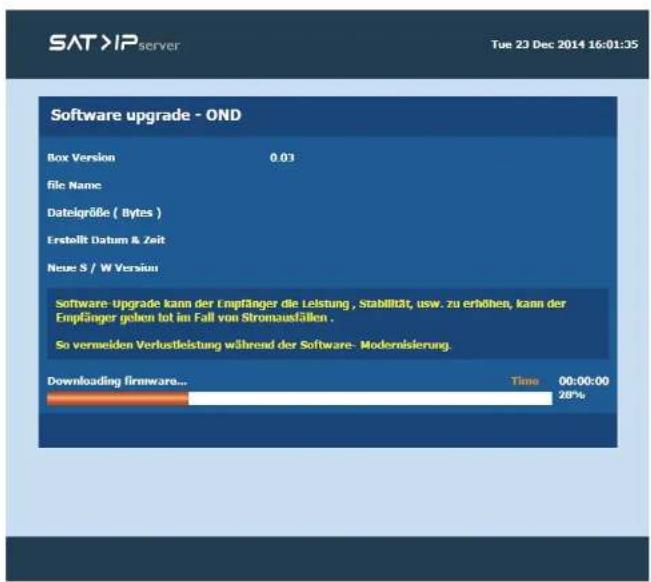
Once user press OK STB starts to connect the server. Once successfully connected with server then downloading will be started.
7. Software Update
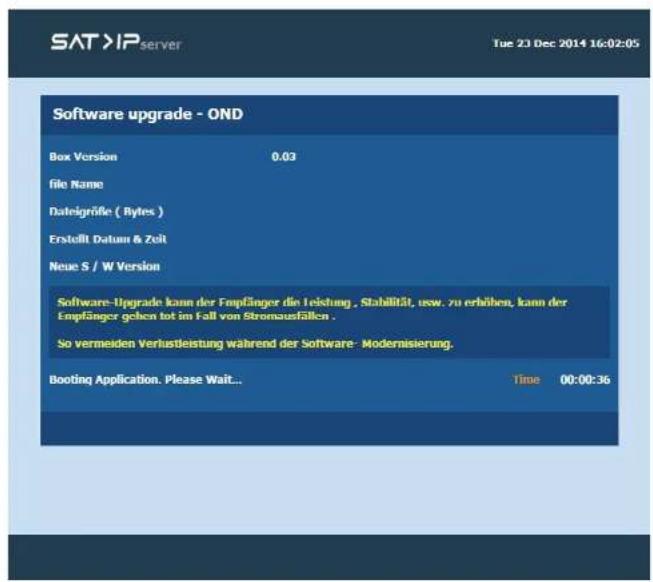
After complete the downloading, box booted with new S/W.
7. Software Update
7.3 WebUI
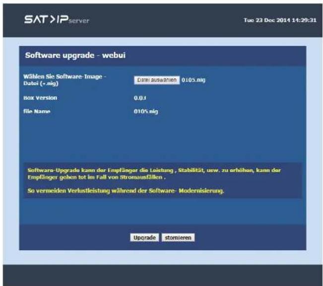
This is simple file based upgrading process by this user can able to upgrade the s/w image from the local PC or from USB device connected to the PC. The s/w image should be of format.nig
7. Software Update
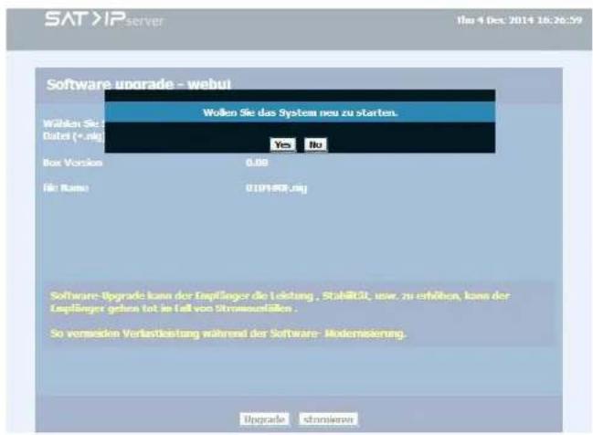
User can able to cancel the upgrade mode with confirmation via press the cancel button.
7. Software Update
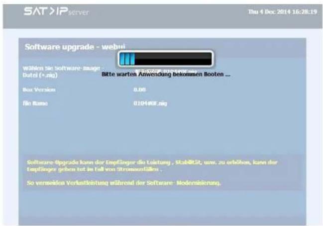
"Please wait application get booting" message get displayed to the user while receiver booting.
8. Admin
Server box supports S/W version display and Password setup mechanism to change the server configuration.
- S/W Version
- Change Password
8.1 SW Version
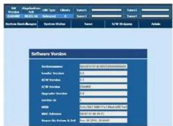
The Version menu displays below informations about the application.
- Serial Mumber
- Loader Version
- HAW Version
• S/W Version - Upgrader Version
- Device ID
- UUID
- MAC Address
• Build Date & Time
8.2 Change Password
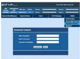
Password for the Web interface can be changed using this „Change password“. Enter the old, new and confirm password into the corresponding input fields & click „Apply“ to confirm the new password.
Default password is "gmi_satip".
9. Specifications
- Processor....STi7108
- Flash 1 MB NOR / 128 MB NAND
• RAM 512 MB / DDR3-1066 - Ethernet....RJ45 10/100/1000
- Specification ....SAT>IP 1.2 compatible
• Video / Audio Unterstützung.....MPEG2 / MPEG4 / TS & PS - Protocol......Unicable, JESS, DISEqC 1.0, 1.2 and USALS
• DVB-S input 4x
Connection via single, twin, quad, Qattro LNB or a multiswitch - USB port for Software Updates
- LED operating lights....green (for On/Off) / red (for streaming)
- Application....Elgato (for use on mobile devices)
• Power supply.....AC 100\~230 Volt, DC 12 V, 3 A - Operating temperature 0° - 40°C
• Power switch.....yes - Dimensions....250 x 135 x 44 mm (L/W/H)
- Weight..../42 g
Note:
Weight and dimensions are not absolutely exact values. Technical details can be changed at any time (according to manufacturer) without prior notice.
Declaration of Conformity
This complies with the following directives / standards is confirmed:
Electromagnetic Compatibility Directive 2004/108/EG
EN 55013:2001 | A1:2003 | A2:2006
EN 55020: 2007
EN 61000-3-2:2006 + A1:2009 + A2:2009
EN 61000-3-3:2008
Low Voltage Directive 2006/95/EG
EN 60065:2002+A1:2006+A11:2008
Notes
Status: 1.0 November 2014 // Technical changes, misprints and errors reserved. Megasat Werke GmbH | Industriestraße 4a | D-97618 Niederlauer | www.megasat.tv | info@megasat.tv
- Bedienungsanleitung
- Inhaltsverzeichnis
- Unicable (Unicable LNB or Unicable multiswitch)
- Content
- Safety Instructions
- Introduction
- SAT-IP Server Features:
- Supported Client devices:
- Connection & How to access
- Connection with a Universal LNB (z.B. Single, Twin or Quad LNB)
- Connection with a Quattro LNB
- Connection with a Unicable LNB
- Connection with a Jess LNB
- Connection with a DiSEqC controlled device
- Connection with a Motor (USALS)
- Identify the IP address
- Configuration
- Login / Logout
- Login
- Logout
- System Settings
- Network Settings
- Wired Network
- Note:
- Wireless Network
- Wired
- Wireless
- LNB Settings
- Quad
- JESS
- DiSEqC1.2
- USALS
- How to Access?
- System Status
- Tuner
- Tuner Settings
- Tuner Test
- Software Update
- Procedure for S/W Upgrade via USB:
- Admin
- SW Version
- Change Password
- Specifications
- Declaration of Conformity
- Notes
Brand : MEGASAT
Model : MEG-4000
Category : Uncategorized