
HBWS-S25 - Water filter HAIER - Free user manual and instructions
Find the device manual for free HBWS-S25 HAIER in PDF.


| Product Type | Water Filter |
| Model | HBWS-S25 |
| Brand | Haier |
| Dimensions (approx) | 27 x 27 x 35 cm |
| Weight | 1.2 kg |
| Power Supply | None (gravity-fed) |
| Filtration Technology | Carbon block and sediment filter |
| Capacity | Up to 1500 liters |
| Flow Rate | 1.5 L/min |
| Main Functions | Reduces chlorine, sediment, bad taste, and odor |
| Maintenance | Replace filter cartridge every 6 months or 1500 liters |
| Safety Features | BPA-free materials, lead-free |
| Spare Parts | Replacement filter cartridge HBWS-S25-Filter |
| Installation | Under-sink or countertop, easy DIY |
| Certifications | NSF/ANSI 42 certified |
| Water Temperature | Cold water only (4-38°C) |
| Warranty | 1 year limited warranty |
Frequently Asked Questions - HBWS-S25 HAIER
User questions about HBWS-S25 HAIER
0 question about this device. Answer the ones you know or ask your own.
Ask a new question about this device
Download the instructions for your Water filter in PDF format for free! Find your manual HBWS-S25 - HAIER and take your electronic device back in hand. On this page are published all the documents necessary for the use of your device. HBWS-S25 by HAIER.
USER MANUAL HBWS-S25 HAIER
natural_image
Exterior view of a modern office building (no signage)海尔牌HBWS-S15型软水机
HB SOFT 10海尔牌HBWS-S10型软水机
海尔牌HBWS-S25型软水机
HB SOFT 15
HB SOFT 25
目录
介绍 1
功能 1
快速操作 3
安装 5
安装条件 6
安装指南 8
运行 10
故障排除 13
产品参数 15
产品保养及维修记录 16
产品保修卡 17
介绍 功能
总则
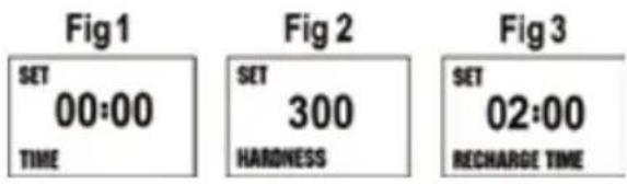
设定当前时间(见图1)
natural_image
Close-up of a black mechanical component with a green circular knob (no text or symbols visible)测试硬度
natural_image
Empty white rectangle with a thin black border (no text or symbols)一.请消费者仔细阅读以下保修条款
Record of Product Maintenance & Repair 19
Product Warranty Card 20
Introduction
General comments
Please read this manual carefully and familiarise yourself with the operating instructions before using the equipment.
Models covered by this manual:
HB SOFT for the device types:
-HBWS-S10
-HBWS-S15
-HBWS-S25
The local standards as well as technical specifications have to be observed.
The operating instructions must be read in conjunction with any national regulations concerning accident prevention and environmental protection.
Prior to putting the device into operation, read the operating instructions completely and thoroughly.
Please keep this manual close to hand for quick reference to the unit's operation.
The device shall only be used for its intended purpose, in line with the operating instructions and only in the environment to which intended.
Note: Never exceed the defined maintenance and service intervals.
Manufacturer
BWT UK Ltd.
Coronation Road, BWT House
High Wycombe Buckinghamshire, HP12, 3SU
Safety instructions

Danger caused by electric current or voltage!
Always consult a qualified electrician when working on places denoted by this symbol.
The complete power supply unit must be replaced in the event of damage to the mains cable.

Warning:
Do not use any aggressive cleaning agents!
If a power failure occurs when regeneration waste water and overflow are being drained into a sump, flooding may occur.

Please observe:
Use only trained or instructed staff. Stipulate clear staff responsibilities for operation, setup, maintenance and repair work.

Please observe:
NEVER operate the device with the housing covers removed.

Note:
If needed, use protective clothing.

Note:
Additional information for the operator.
Intended use
The domestic application HB SOFT is designed for softening or partially softening domestic water (in accordance with the relevant regulations.) All other use is strictly forbidden and your own responsibility.
Scope of delivery
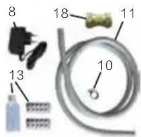
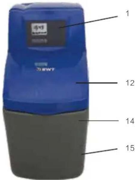
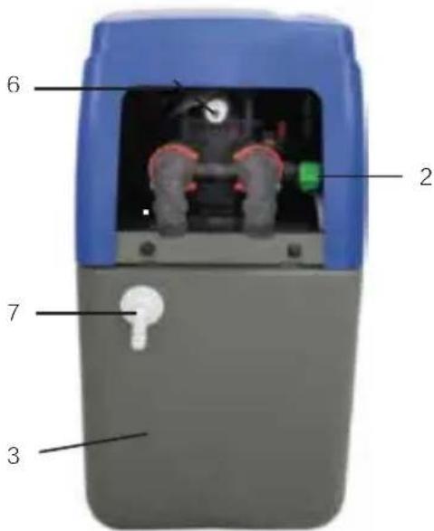
HB SOFT water softer with: Standard delivery:
- Multi-way control valve with microprocessor controller
2.Blending valve - Softening column with ion exchange resin
- Softened water outlet
- Hard water inlet
6.Drain water - Overflow connection
8.Mains plug power supply connection - Installation and Operating Manual (IOM)
- Hose clamp connection
11.2 m drain water hose (flexible) - Access cover with short user instructions
13.AQUATEST hardness tester
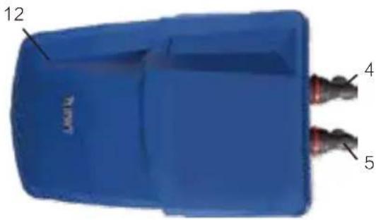
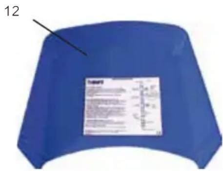
Please open the access cover (12), (See page 9): - Salt storage container
- Brine cabinet
- Fixing material (See page 9)
- Rating plate and serial number (See page 9) Additional delivery:
- Non-return valve BSP: 34 (DN: 20/20)
Display and control elements
Note: In the programming mode the respective >target value< flash. 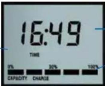 | The display shows: the current time and the remaining capacity in % | ||
 |  |  |  |
| [UP] [DOWN] [SET] [RECHARGE] | |||
| = Moves cursor changes entries = Confirms entries | = Programming recharge tonight | ||
Standard factory settings
Duration of the step times: Regeneration time:
Depending on the internal settings of the unit (a few minutes)
free input at RECHARGE TONIGHT
Hardness of drinking water / capacity:300 ppm, 1566
litres for 10 litre model
| HB SOFT 10, 15, 25 | Standard |
| Display | Yes |
| Operating range | UK/EU |
| Recharge tonight | Yes |
| Salt alarm | No |
| Salt setting – care cubes (CC) | UK/EU |
| Salt setting – block salt (BS) | UK only |
Note for the initial softener settings:
Setting the time of day:
On first powering up the softener the digits of the display will flash while the valve rotates to service position, the valve can be heard moving, this can take a few minutes. On locating service position the display will prompt the installer to set the time. Start by pressing the SET/RETURN key, this will make the hour digit to flash, press the UP/DOWN key to adjust to the correct hour, once set, press the SET/RETURN key, this will make the minutes digits flash, use the UP/DOWN key to adjust the minutes. Throughout the settings mode use the UP/DOWN keys on the softener display to toggle or adjust settings and use the SET/RETURN key to store the setting and move on to the next field in the menu.
Programming procedure
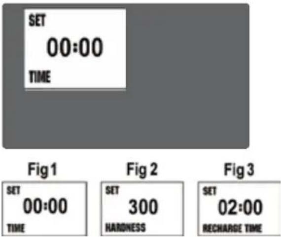
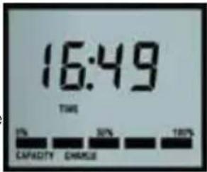
Setting the time of day (see Fig. 1)
The first two digits (00) of the display will flash prompting the installer to set the time.
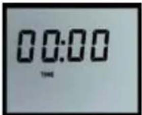
The time is adjusted by using the [UP], [DOWN] keys. Pressing the [SET] key enters the hours. The minutes are set by using the [UP], [DOWN] keys.
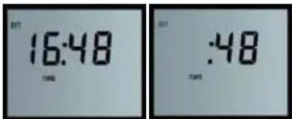
Pressing the [SET] key once enters the minutes and moves the display into the Set Hardness mode.
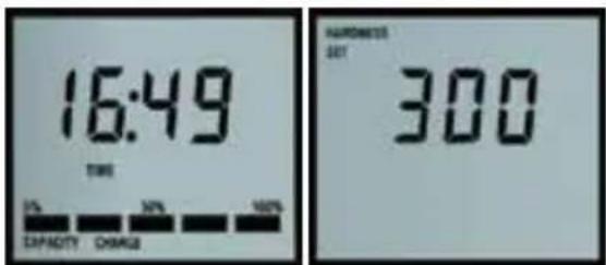
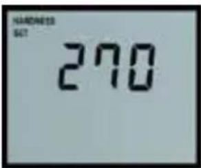
Setting the water hardness (see Fig. 2)
The display default is 300 ppm (typical hardness level) which indicates a setting suitable for hard water with a value of 300 parts per million of hardness minerals. Use the keys [UP] [DOWN] keys to adjust the setting to match that of the one you obtained / identified earlier. See page 6 for details.
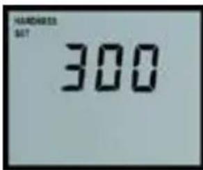
Pressing the [SET] set key once enters the hardness and moves the display to Set Recharge Time Mode.
Setting the recharge time (see Fig. 3)
To operate effectively, your water softener needs to regenerate periodically (dependent on the hardness of the supply and amount of water used). The default time of day when this is to occur is 2:00 a.m.. To alter this setting use the [UP] [DOWN] keys.
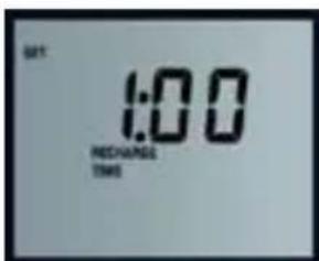
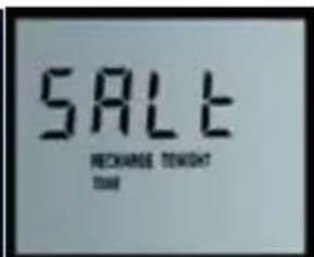
Pressing the [SET] key once enters the recharge time and moves the display into Set Salt Type Mode.
This option “SALt” is only available on certain models – not standard.
Installation
Installation requirements
National guidelines and regulations:
Observe all applicable installation regulations, general guidelines, hygiene requirements, and technical specifications. The hard water to be fed into the unit must always meet the specifications of the national Drinking Water Ordinance or EU Directive 98/83/EC. The total dissolved iron and manganese may not exceed 0.1 mg/l. The hard water to be fed into the unit must always be free of air bubbles.
Frost protection and ambient temperature:
The installation site must be free of frost and kept free of chemicals, paint, solvents and fumes.
The ambient temperature should not exceed 40^ C, even before the machine is started. Please avoid direct heat sources, e.g. radiators and exposure to sunlight.
General safety:
The rated mains power (see technical data) and the requisite inlet water pressure must be present at all times. No protection against a lack of water is provided. This must be installed onsite if required.
Overpressure and fluctuation protection:
Attention: Water pressure must never exceed the unit 's maximum of 5.0 bar UK, 8.0 bar EU.
If the network water-pressure is higher than 4.0 bar UK, 6.0 bar EU (or you are unsure about pressure), a pressure reducer (pressure reducing valve) must be installed upstream of the unit.
During pressure fluctuations or surges, the sum of the pressure surge and the standing pressure is not to exceed the nominal pressure.
Electrical interference:
The emission of interference (EMI = voltage peaks, high-frequency electromagnetic fields, interference voltages, voltage fluctuations…) by the surrounding electrical systems may not exceed the maximum values specified in EN 61000-6-3.
Data analysis of the hard water in your area:
Continuous operation of the water softener with water containing chlorine or chlorine dioxide is possible if the concentration of free chlorine/chlorine dioxide does not exceed 0.5 mg/l. The type of pretreatment must be determined individually.
Principle of intelligent regeneration:
The unit should be sized according your current water consumption. If water consumption is reduced, e.g. during holidays, a shut-off device must be fully opened for at least 5 minutes before water can be used again.
Inlet- and outlet connections:
When installing the unit, select a location where the unit can easily be connected to the water supply network. A connection to the waste water system (at least DN 50), a floor drain and a separate mains socket (see technical data) must be nearby.
Overflow hose connection:
A suitable overflow hose connection is required to remove the waste water.
Preconditions for the hydraulic installation:
Observe the hydraulic and electrical requirements for installation for first commission. (see “chapter 5”)
Exclusion of warranty:
Non-compliance with the installation conditions and the operator responsibilities voids the warranty.
Guarantee:
In the event of a malfunction of the unit during the guarantee period, please contact your after-sales service department and quote the model type and the production number (see technical data or the rating plate on unit).
Note: Only your local after-sales service staff may perform any works under the guarantee.
Any work performed by a third party must be directly commissioned by your after-sales service.
Initial commissioning
or professional installation by a qualified fitter.
-Has all packaging material (16) been removed from the brine cabinet?
–Is there a protective filter upstream from the unit in the immediate vicinity?
-Is the water and power supply to the unit continuous (network pressure of at least 1.7 bar UK /1 bar EU)
- Have you opened the pressure reducing valve to the limit stop?
- Have the water hoses been properly connected?
-(Observe the flow direction arrows and hard water inlet at the non-return valve of the unit).
- Have the drain water hose and the overflow been routed separately to the waste water system and connected? (See Installation)
- Have you informed the operator of the inspection schedule? (Check supply of salt and hardness of blended water at least every two months)
- Have you informed the operator of the maintenance schedule? (Tasks in accordance with manufacturer's instructions. Interval annually, every 6 months with communal units)
Please check connections and pipeline junctions for leaks.
Handing over the unit to the operator:
If there is a delay between the installation/start-up of the unit and transfer to the operator, a manual regeneration must be performed. The operator must be told how the unit works as well as how to operate and inspect it. Ensure that the operator receives the installation and operating manual.
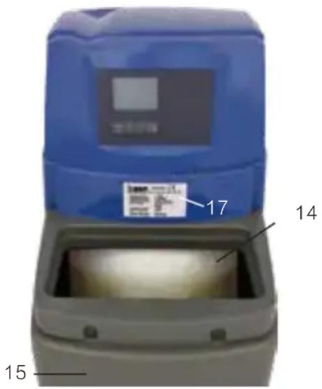
Please open the access cover (12)
- Salt storage container
- Brine cabinet
- Fixing material (not seen)
- Rating plate and serial number
Installation and operation considerations
1. Before you begin
The installation of your new water softener is relatively straightforward. However, we would recommend that either a qualified plumber or a person with relevant plumbing experience carries out the installation.
Before embarking on the installation, please ensure you have familiarised yourself with both these instructions and the components required to complete the installation.
2. Positioning the water softener
Please measure your water softener to ensure that it will fit into the area you are placing the unit into. PLEASE remember to include additional space for connecting pipe work in your calculations along with the regular access that is needed for topping the unit up with salt and future service.
Where possible, the distance of both the incoming water supply and nearest drain should be kept to a minimum. Two metres is an ideal distance, however, longer distances are permissible, dependant
16 on the incoming water pressure.
14 Please remember the weight of your new water softener will considerably increase once installed and filled with salt. Therefore, please ensure your chosen location is strong enough to support an approximate total weight of (see table). Your new water softener has been designed to operate efficiently and effectively with an incoming water pressure of between 1.7 to 5.0 bar UK, 1.0 to 8.0 bar EU. If your water supply is likely to fall outside
these limits, then we would recommend that a booster pump or pressure reducing valve should be fitted respectively.
Operating pressure
3.5 bar UK /
4.5 bar EU
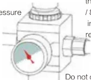
If pressure more than:5.0 bar UK
/ 8.0 bar EU
install pressure reducing valve
Do not operate with a pressure less than: 1.7 bar UK / 1.0 bar EU
Important - Never install the water softener where it, or its connections (including the drain overflow lines) will be subject to temperatures under 0^ C or above 40^ C.
If you are planning to install the water softener above ground level e.g. In the loft, the following instructions should be strictly adhered to.
Loft installation
The water softener should be installed within a container of not less than 100 litre capacity, to which there should be connected an overflow pipe of not less than 20mm diameter. The overflow should be connected at the bottom of the container and not less than 15mm below the height of any electrical components mounted on the water softener. It is recommended that an anti vacuum valve be fitted to the inlet pipework supplying the water softener.
Plumbing systems
There are several types of plumbing systems in common use:
For 15mm pipework (e.g. Static Head systems) The water softener can be supplied optionally with a high flow installation kit and flexible high flow hoses suitable for 22mm pipework, for 15mm pipework use the reducing bushes supplied with the kit, (see diagram on page 9).
Backflow prevention device
When fitted to the supply feeding a single dwelling, a check valve complying with national regulations must be fitted on the cold water feed prior to the installation. All other types of installation require the fitting of a double check valve.
Drinking water
Your water softener installation must include at least one drinking water tap that is not fed by the water softener.
Observe: In case of low sodium diet follow the local “department of health ‘s” advice concerning the use of softened water for drinking.
Note: Water that is used for mixing powdered milk for babies must only be taken from an unsoftened mains tap as some powdered milks and softened water both contain sodium for which young babies have a limited tolerance.
Reference Data for Hardness Adjustment
Please test the water hardness and, if required, use the chart to convert hardness settings to „parts per million “ (ppm) and refer to chapter 4.3.
The specific hardness conversion chart for capacity of the time-clock operation is listed in the last column.
| HB SOFT e.g. 10 litres | |||
| M3/° F (50) | |||
| d° H | f° H | ppm (mg/l) | capacity |
| 5.6 | 10.0 | 100 | 5000 |
| 6.2 | 11.0 | 110 | 4545 |
| 6.7 | 12.0 | 120 | 4167 |
| 7.3 | 13.0 | 130 | 3846 |
| 8.4 | 15.0 | 150 | 3333 |
| 10.1 | 18.0 | 180 | 2778 |
| 11.2 | 20.0 | 200 | 2500 |
| 12.3 | 22.0 | 220 | 2273 |
| 13.4 | 24.0 | 240 | 2083 |
| 14.6 | 26.0 | 260 | 1923 |
| 15.7 | 28.0 | 280 | 1786 |
| 16.8 | 30.0 | 300 | 1667 |
| 17.9 | 32.0 | 320 | 1563 |
| 19.0 | 34.0 | 340 | 1471 |
| 20.2 | 36.0 | 360 | 1389 |
| 21.3 | 38.0 | 380 | 1316 |
| 22.4 | 40.0 | 400 | 1250 |
| 23.5 | 42.0 | 420 | 1190 |
| 24.6 | 44.0 | 440 | 1136 |
| 25.8 | 46.0 | 460 | 1087 |
| 26.9 | 48.0 | 480 | 1042 |
| 28.0 | 50.0 | 500 | 1000 |
| 29.1 | 52.0 | 520 | 962 |
| 30.3 | 54.0 | 540 | 926 |
| 31.4 | 56.0 | 560 | 893 |
| 32.5 | 58.0 | 580 | 862 |
| 33.6 | 60.0 | 600 | 833 |
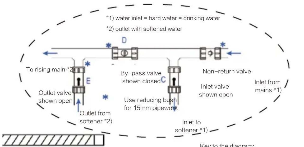
flowchart
graph TD
    A["To rising main *2"] --> B["Outlet valve shown open"]
    B --> C["Outlet from softener *2"]
    D["By-pass valve shown closed"] --> E["Use reducing bush for 15mm pipework"]
    F["Non-return valve"] --> G["Inlet valve shown open"]
    G --> H["Inlet from mains *1"]
    I["*1) water inlet = hard water = drinking water\n*2) outlet with softened water"] --> J["*"]
    K["Key to the diagram:"] --> L["Diagram: Level indicator"]
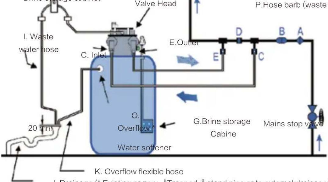
Key to the diagram:
A. Non return valve
B. Pressure reducing valve (where required)
C.Inlet valve (hard water) "
D.Bypass valve
E. Outlet valve (soft water) ^3 “
F.Mains stop valve
Brine storage cabinet
Valve Head
I. Waste water hose
C. Inlet
O.
Overflow
Water softener
G.Brine storage Cabine
Key to the diagram:
H.Fixing clip for flexible hose
I. Waste water hose
J.Connection for drain
K.Flexible hose, Overflow
L. Control valve (green)
M.Servo-motor for valve positioning
N.Distance device and ceiling of room
O.Overflow connection "
P.Hose barb (waste water trap)
flowchart
graph TD
    A["1. Waste water hose"] --> B["20 mm"]
    B --> C["C. Inlet"]
    C --> D["Valve Head"]
    D --> E["E. Outlet"]
    E --> F["D"]
    F --> G["B"]
    G --> H["A"]
    H --> I["Mains stop valve"]
    I --> J["G.Brine storage Cabine"]
    J --> K["O. Overflow"]
    K --> L["Water softener"]
    L --> M["K. Overflow flexible hose"]
    M --> N["P.Hose barb (waste)"]
J. Drainage (* Existing or new “Trapped “ stand pipe or to external drainage)
Observe a minimum distance to the ceiling (N) of 0.5 m.
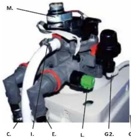
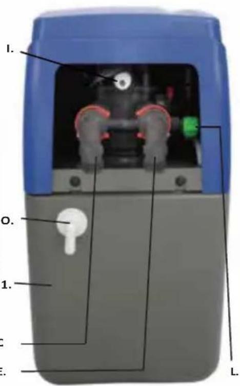
Technical overview of device:
C. Inlet connection (feed water) → for flexible hose, with thread 34 “
E. Outlet connection (softened water) → for flexible hose, with thread 34 “
G1. Brine storage cabinet → salt filling
G2. Connection to brine → internal connection
O. Overflow connection → for flexible hose, threadless 12 “
L.Control valve → flow regulation
M.Servo motor → for control valve
I. Waste water connection → external drainage of waste water
Attention: Pipework (J) sized min. DN50. Use only the flexible DN20 hoses included in the delivery. Ensure a correct sealing and setting of all pipes before first commissioning.
Attention: To comply with good plumbing practice the external waste-water-drainage must have a minimum space of air: 20mm (according to guideline EN 14743).
Attention: Drainage from the overflow of the brine tank, Connections between the channel and two flexible hoses (according to standard EN 3131).
Protection of device: To increase the lifetime of your softener ensure it is kept in a clean, dry place with an ambient temperature between 5 and 40°C. Do not mention damage to resin or components.
Installing your softener
1. Positioning the water softener:
It is very important to establish the water pressure before installing the water softener. If the water pressure is low then the water softener may not operate effectively. If it is too high, then components inside the unit may be damaged.
Water pressure should be tested with a gauge at the kitchen tap or outside tap. It should be noted that water pressure can increase at periods of low water usage e.g. overnight. If therefore, the daytime pressure exceeds 5.0 bar UK, 8.0 bar EU or if you are unsure about pressure, then a pressure reducing valve should be fitted.
Where the pressure is less than 1.7 bar UK, 1.0 bar EU a booster pump may be required.
2. Inlet and outlet connections:
With the bypass valve open and the inlet / outlet valves closed the unit can be connected to the plumbing system. Arrows on the inlet and outlet piping from the valve will confirm the direction of flow. Connections can be made with either conventional copper tube and fittings or the high flow flexible hoses supplied, ensure hoses are not kinked as this may restrict flow.
3. Drain connection:
Push the flexible drain hose onto the barbed connector (Drain) as shown on page 29 and secure with the clip provided. Run the drain hose to a stand pipe or to a drain. The air gap needs to be at least 20 mm. Softened water will have no adverse effect on a septic tank. You can extend the drain up to 9m if you have sufficient pressure (greater than 3 bar). The drain hose must not be kinked or restricted in any way as this will cause an overflow from the brine cabinet.
Frost protection:
If the drain hose or connecting pipework is likely to be subject to temperatures below 0^ C it must be protected to prevent freezing. Failure to observe this precaution could lead to the water softener overflowing.
Raising the drain hose:
If you have a water pressure of 3 bar or more, you can raise the drain to a maximum of 3 metres above the valve head.
4. Overflow connections:
The hose barb overflow pipe (not supplied with the softener) should be connected to the push fit elbow at the rear of the cabinet (see page 30 - letter O). Run the pipe downhill to the drainage. Take care that the overflow does not discharge where damage could occur.
If the water softener is fitted in a cellar or basement, the overflow can be run to a storage tank.
Do not elevate the overflow hose.
Note: Do not use jointing cement on the fitting.
5. Electrical connections:
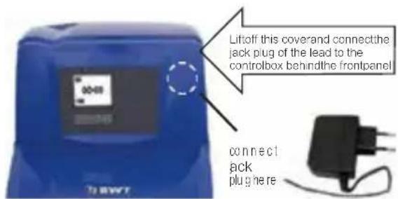
For added safety, peace of mind and ease of installation, your water softener is powered by low voltage via a plug in transformer. This transformer must be connected to a switched socket.
Attention: Plug the transformer into the socket with the switch in the OFF-position.
6.Filling the brine cabinet, salt- usage and alarm:
Now place the water softener salt in the brine cabinet. Use the care cubes (tablet salt) or block salt (UK), from your local dealer.
Notes on salt usage: Your water softener will only perform effectively if there is salt in the brine cabinet during the regeneration process.
It is therefore essential that the salt level does not fall lower than 15 cm in depth when measured from the base of the brine cabinet. N.B. The softener requires no priming, add no water to the brine tank. During regeneration, salt will not enter your water system as the salt used in the regeneration process is rinsed safely away to drain.
Salt alarm is optional – not standard on most models. Depending on your model your water softener may be equipped with a low salt alarm, this monitors your salt usage and sounds an audible alarm while displaying the low salt error code "SALt" when your salt levels falls to the minimum level. To reset the salt alarm fill the system with salt and press the SET-key.
7. Blending control:
All machines are factory set to produce water that is soft. Note:
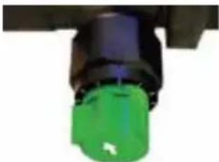
If you prefer water which is less soft, turn the blending knob on the left side of the valve anti-clockwise until the water meets your
requirements.
natural_image
Close-up of a green and black mechanical component (no visible text or symbols)8. Testing for the water hardness in your area:
Water hardness can vary from one location to another. To determine the hardness of the water feeding your water softener (unsoftened supply) use the hardness test kit supplied.
-Fill the test bottle supplied to the fill line with water from a hard water tap.
- Add the tablets to the solution one tablet at a time.
-Shake the bottle in between and keep adding tablets to the water until the solution turns from wine red to blue, record the number of tablets as you go.
-Using the data table supplied with your kit, match up the number of tablets with the hardness. You will need this figure when programming your water softener in the next section of this manual.
9. Switching on for the first time:
-Check that the inlet hoses and outlet hoses or couplings are properly connected i.e. inlet-to-inlet, outlet-to-outlet.
The by-pass arrangement (see page 9) should be in the open position in example:
-the inlet and outlet valves closed (E), (C)
-Check that the by-pass valve (D) open
-Check that the mains stop valve (F) open.
-Check that the Brine Cabinet (G) contains salt.
-Check that the water softener is connected to the drain (J) and the overflow pipe is be linked to each other connected.
Note: The drain and overflow must not be linked to each other.
-Gently open the inlet valve (C) so that water flows into the resin vessel.
-Turn ON the power, you will hear the valve move quietly into the start position. When the positioning process has been completed (which can take up to 5 minutes) you will hear the movement stop, the valve has now reached its start position in preparation for the programming procedure.
-Close the by-pass valve (D).
-Gently open the outlet valve (E).
-Check for leaks, take corrective action to stop leaks if required.
-Your water softener is now on line and you may start the valve programming procedure set out in the next section of this manual.
Operation
Function settings
Capacity requirement-dependent of the unit controller:
The unit operates according to the principle of intelligent regeneration. The average capacity level of each model is preset and updates automatically to the actual consumption within 14 days.
The presetting is appropriate for the most common applications. It is not necessary to adjust the unit for individual requirements.
Intelligent quantity-dependent regeneration:
When the unit is started, the available supply of softened water is programmed (depending on the hardness of the water).
At a user-defined time (e.g. at night), the unit checks whether the remaining supply of softened water is sufficient for the following day. If this is not the case, the softening column is regenerated by only the exact percentage necessary to fully replenish the supply of softened water to 100%.
Note: With intelligent regeneration, the remaining supply of softened water is not wasted.
This intelligent regeneration method is possible because of the precision flowmeter, which is able to adjust the amount of brine required for partial regeneration. The consumption of regenerative and water is reduced to the required minimum.
In the event of a power failure, the data and the time are retained (for a limited amount of time).
Options: The unit is optionally equipped with a device that disinfects the ion exchange resin during the regeneration. A spring-loaded non-return valve (18) is optionally available (see page 5).
Automatic regeneration triggering:
This is an optional setting - not as standard on all softeners.
Operation (workflow)
Setting the Type of Salt used:
To operate effectively, your water softener must be set to the type of salt you intend to use in the system. Salt pellets are suitable.
Pressing the [SET] button will return the display to the Normal Operation mode. Programming is now complete and no further adjustment of the water softener is required. Remember to check the salt and water level in the brine cabinet weekly.
Charge Bar:
Having set the display on the control facia, you will notice that during normal operation there is a charge bar running along the bottom of the display. This charge bar shows the percentage of water softener capacity remaining since the last regeneration. Immediately following a regeneration, the charge bar returns to 100%.
Resetting the display during operation:
If the time is to be adjusted during normal operation, press any key to illuminate the display, press the [SET] key once. The display will flash and indicate present time. Using the keys will alter the time as described on page 24.
Power loss:
The AMECS system will maintain the individual programming parameters of the water softener for a few hours.
If the power cut lasts longer than a few hours, the control will flash “00:00” when power is returned to the control. The unit will continue to keep time from the moment power is restored. In this situation the time of day will need to be reset.
Flow indicator:
During normal operation, a flow indicator will flash on the display at a rate of one litre per pulse when water is passing through the softener.
Cleaning:
Your water softener may be cleaned using a damp cloth and a mild detergent. Do not use bleaches, solvents or spirits as they may damage the surfaces.
Manual regeneration [recharge] button:
Under normal operating conditions your water softener will regenerate automatically and you should not normally have to regenerate the unit manually. If however a manual regeneration is required then follow the procedure set out below.
- Press any key to illuminate the display.
- Momentarily pressing the button (symbol underneath the display and furthest to the right) will illuminate Recharge Tonight on the display and perform a regeneration at 2.00 a.m. regar less of the remaining water softener capacity.
- If the button is subsequently pressed, this will clear the Recharge Tonight indicator from the display and cancel the Recharge Tonight feature. If the [recharge] button is pressed down for six seconds, the controller will flash the Recharge display and immediately commence the regeneration cycle which cannot be cancelled.
Adding regenerative salt:
Refill the salt no later than when SALt is indicated on the display or the current filling is 15cm above the base of the salt storage container.
Acknowledge – low SALt alarm:
NOTE: This function is optional – not standard on all models.
Open the cover (4). Pour regenerative into the storage area (5).

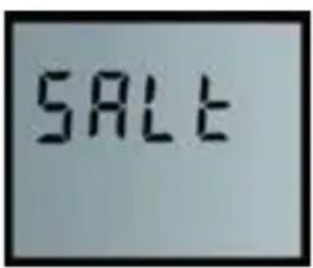
Press [SET] and hold until the SALt display goes out. Refill the unit in such a way that no dirt can get into the salt storage container (14) (if necessary, clean the packages containing the salt before use).
Clean the salt storage area (14) or brine cavity (15) with clean water if it gets dirty..
Salt usage:
Your water softener is controlled by a microprocessor which constantly monitors water usage.
The system will build up a history of your water requirements and calculate the most economical regeneration pattern. This will ensure a constant supply of softened water whilst maintaining high levels of water and salt efficiency. As your water softener uses a proportional brining system, more frequent regenerations do not necessarily mean high water/ salt usage.
Increase in number or residents:
Sudden changes in your water usage should not affect your water softeners performance. If however, the number of guests staying with you increases, you will notice that the water usage patterns will alter. This may cause your water softener to regenerate more often than normal. As the water usage returns to its normal level, the number of regenerations will also return to normal.
Cabinet Water Level:
During normal operation the water level inside the water softener cabinet will rise and fall as required by the regeneration process. If the water softener is used within the specified operational parameters the water level should not reach the overflow connection. If however an overflow situation occurs please refer to the troubleshooting section on page 17 to diagnose the problem.
Following any overflow situation reduce the water level by half and initiate a manual regeneration as described above.
NB: Check the water level weekly and following any unplanned event, e.g. powerfailure.
Setting the hardness of blended water
The unit is preset to 300 ppm.
To test the water hardness, allow the nearest cold water tap to run for a while and check the hardness of the blended water using the AQUATEST hardness tester.
Adjust with the blending valve “V” until the desired value is reached.
| Hardness in ppm | No. of people | ||||
| 02 | 03 | 04 | 05 | 06 | |
| 150 | 8 | 7 | 6 | 5 | 4 |
| 200 | 7 | 6 | 5 | 4 | 3 |
| 250 | 6 | 5 | 4 | 3 | 2 |
| 300 | 5 | 4 | 3 | 2 | 1 |
| 350 | 4 | 3 | 2 | 1 | 1 |
| 400 | 3 | 2 | 1 | 1 | 1 |
= Days between regeneration
Maintenance
Maintenance work
The operator must regularly perform the following checks to guarantee that the unit functions properly.
Check the regenerative and refill after use.
Check the water hardness: The hardness of drinking water and the set blended water hardness must be checked 2x annually and the hardness of the blended water must be corrected when required (see Start-up).
Check for leaks, visual inspection: Check connection lines and connections for leaks.
Check for dirt in the regenerative storage area and brine cavity every two months and clean and flush with clear water if necessary. The intervals between checks are recommended minimums and must be adjusted according to site conditions.
Operator responsibilities
All technical equipment requires regular servicing in order to guarantee optimal functionality.
Keep yourself up to date with regard to the quality and pressure ratio of the water which is to be treated. If the water quality changes, the settings may need to be changed. Consult a specialist if this is the case.
Regular checks by the operator are required for the warranty and proper functioning of the unit. The water softener must be inspected regularly in accordance with the conditions of operation and use.
Operator checks intervals:
After use: Refill regeneration salt
2x Annually: Check pressure
2x Annually: Check water quality
1x Annually: Clean brine container
Maintenance & wearing parts
Wearing parts must also be replaced within the prescribed maintenance intervals in order to guarantee functionality and fulfil the warranty conditions. The water softener should be serviced once a year.
Wearing parts may only be replaced by qualified personnel (fitters or after-sales service team).
We recommend that you enter into a maintenance agreement with your fitter or the aftersales service team.
Cleaning information: Do not use alcohol or alcohol based cleaning agents, otherwise the plastic surfaces of the device will be damaged.

At the end of product life please contact Customer Services to arrange a new replacement for your softener.
Disposal of your softener and any electrical parts (e.g. 0.22 F capacitor battery, 5.5 V) should only be carried out at authorised WEEE recycling centres.
Trouble shooting Guide

6.1 Attention:
If your water softener is not performing as it should, please run through the check list below.
| Checklist | Solution | Page |
| Problem: Water still remains hard. | ||
| Is there a minimum of 150mm of salt in the brine cabinet? | Fill the brine cabinet with salt. | 12 |
| Is the power on? | Switch the power on and check connections. | 12 |
| Is the softener online? | Close the by-pass valve and open the inlet and outlet valves. | 12 |
| Is the hardness setting correct? | Reset the hardness if required. | 12, 15 |
| Problem: Water level in brine cabinet reaches overflow. | ||
| Is the line pressure within the specification of the water softener? | Connect a pressure gauge to a water outlet and check the pressure is between: 1.7 - 5.0 bar for the UK / 1.0 - 8.0 bar for EU. | 5, 6, 7 |
| Pressure falls outside of the water softener specification. | Fit a pressure reducing valve or booster pump as required. (see note below) | 5, 6, 7 |
| Is there flow through the drain line? | Check the drain line is not kinked, blocked or frozen. | 9, 10 |
| Has there been a power interruption? | Check that the power is on and the connections are secure. | 5, 13 |
| Problem: No water. | ||
| Is the mains stop valve open? | Open the mains stop valve. | 12 |
| Are the inlet and outlet valves of the water softener open? | Open the inlet and outlet valves to the water- softener. | 12 |

Note:
If any overflow situation occurs or if any of the above requires action reduce the water level by half and initiate a regeneration by pressing and holding the manual regeneration key [RECHARGE] for more than six seconds.

Attention:
If your water softener is not performing as it should, please run through the check list below.
| Checklist | Solution | Page |
| Problem: Water runs from the drain constantly. | ||
| Is the unit in recharge mode? | If yes, this is normal, wait until the recharge is complete. | 4 |
| Is the power on? | There should be no flow to drain in the service position. | 5 |
| Problem: Excessive salt usage. | ||
| Check the hardness setting. | Reduce the hardness if incorrect. | 4, 15 |
| Problem: Electronic Display. | ||
| The display shows error code: “Err 1“, audible alarm sounds, (see note below). | Check all the connections are secure.Turn the power off for 10 seconds then turn back on, allow the system to reset. | 14 |
| OPTIONAL: The display shows error code: “SALt“, audible alarm sounds. | The low salt alarm is active. Fill the brine ca- binet with salt. Pressing the [SET] key will reset the salt alarm to full capacity of salt. | 14 |
| Is the digital display blank? | Check the power is turned on and all the connections are secure. | 14 |
| Problem: Unit regenerates at the wrong time. | ||
| Is the present time correct? | Reset the present time. | 4 |

Note:
If the home position is not detected within 10 minutes, the main display will show an "Err 1" message to indicate a controller error and an audible alarm will sound. The error condition can only be cleared by removing and reapplying the power.

Attention:
If problem persists, please call your local dealer or after sales service team
| Product Name | Haier HBWS-S10 Water Softener Haier HBWS-S15 Water Softener Haier HBWS-S25 Water Softener | ||
| Product Type | HBWS-S10 | HBWS-S15 | HBWS-S25 |
| Flow Rate | 1.5m^3/h | 2.0m^3/h | 2.5m^3/h |
| Nominal Capacity | 800m^3 | 1000m^3 | 1400m^3 |
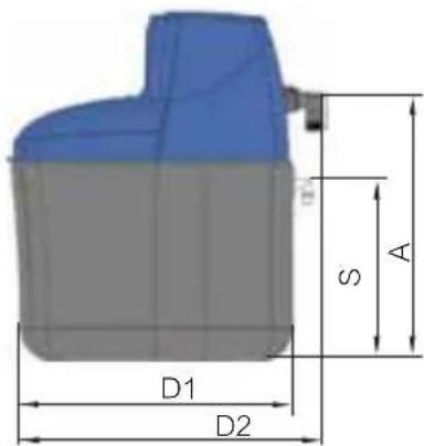
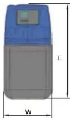
| Product Size(mm) | 270x480x532 | 270x480x602 | 270x480x804 |
| Packaging Size(mm) | 365x600x665 | 365x600x665 | 365x600x885 |
| Net Weight | 18kg | 22kg | 31kg |
| Gross Weight | 20kg | 24kg | 33kg |
| Pipe Diameter | DN20 | ||
| Type of Electric Protection | Kind I | ||
| Country of Origin | Britain | ||
| Water Temperature | 5-30°C | ||
| Ambient Temperature | 5-40°C | ||
| Water Pressure | 0.1-0.8MPa | ||
| Water Supply | Tap Water | ||
| Nominal Power | 15W | ||
| Implementation Standard | GB4706.1-2005 GB/T30307-2013 | ||
| MOH No. | 鲁卫水进字(2019)第B004号 | ||
| Water Quality | Sanitary Standard for Hygienic Safety and Function Evaluation on Treatment Devices of Drinking Water - General Device (2001) | ||
| Actual Manufacturer | BWT UK Ltd. | ||
| Actual Production Address | Coronation Road, BWT House, High Wycombe, Buckinghamshire HP12 3SU | ||
| Responsible Company in China | BWT Haier Drinking Water Technology Co., Ltd | ||
| Address | Qingdao Sino-German Eco Park, Beta Space, Room 216,172 Taibaishan Rd., Huangdao District, Qingdao, Shandong, China | ||
Product type: Purchase date:
Record of Product Maintenance
| Maintenance Date Maintenance Content Service Person Signature | ||
In order to ensure the product can be operated properly and filter out high-quality purified water, please carefully read the instruction manual and replace the filter material on time.
Record of Product Repair
| Maintenance Date Maintenance Content Service Person Signature | ||
Note: Please keep this card properly and show it during maintenance and repair.
Product Warranty Card
Thank you so much for purchasing Haier BWT inside products!
If the products purchased through regular channels are non-artificially damaged, we will provide a 2-year free warranty service from the date of installation.
For installation, please call the service hotline: 400-895-9910, from 9: 00 to 17: 00 Monday to Friday (except for legal holidays).
Product category: ____ Card number: ____
Product Type: ____
Purchase date: ____
Purchase venue: ____
Sales person: ____
natural_image
Empty white rectangle with a thin gray border (no text or symbols)I. Please read the following warranty terms carefully
-
Please check that the serial numbers on product package and on this card are consistent and valid, and please completely, correctly and truly fill the acknowledgement of receipt together with the installation person.
-
Please keep the warranty card and purchase invoice properly.
-
Please show the original warranty card or invoice (warranty card and invoice shall not be altered, otherwise invalid).
II. Any of the following problems during the warranty period can enjoy free service.
-
The product has quality problems such as leaking on tank or natural breakage of outer box. The company is responsible for warranty; however, damage due to collision or harmful gas and liquid is not covered by the warranty.
-
Use it under the condition of meeting the power supply voltage and water supply pressure required by the product.
III. Any one of the following circumstances is not covered by the warranty. The company or its authorization service center will charge a reasonable fee for repairs.
-
The user cannot show warranty card or invoice;
-
The product warranty card is inconsistent with the actual warranty goods or altered;
-
Damage or other losses caused by improper use or human activities:
-
Damage and other losses caused by using under the power supply voltage, water supply pressure, ambient temperature that meet the requirements of technical specifications;
t's broken down.
Acknowledgement of Receipt (Distributor's)
Card no.: ____
User name: ____
User phone no.:
Contact address: ____
Postcode: ____
Email:
Purchase date: ____
Product type: ____
Dealer name: ____
Installation person: ____
Installation date: ____
User signature: ____
Cut area
Acknowledgement of Receipt (Company's)
Card no.: ____
User name: ____
User phone no.: ____
Contact address: ____
Postcode: ____
Email: ____
Purchase date: ____
Product type: ____
Dealer name: ____
Installation person: ____
Installation date: ____
User signature: ____
Haier
BWT INSIDE

- 目录
- 介绍 功能
- 总则
- 设定当前时间(见图1)
- 测试硬度
- 一.请消费者仔细阅读以下保修条款
- Introduction
- General comments
- Manufacturer
- Safety instructions
- Intended use
- Scope of delivery
- Display and control elements
- Standard factory settings
- Note for the initial softener settings:
- Setting the time of day (see Fig. 1)
- Setting the water hardness (see Fig. 2)
- Setting the recharge time (see Fig. 3)
- Installation
- Installation requirements
- National guidelines and regulations:
- Frost protection and ambient temperature:
- General safety:
- Overpressure and fluctuation protection:
- Electrical interference:
- Inlet- and outlet connections:
- Overflow hose connection:
- Exclusion of warranty:
- Guarantee:
- Initial commissioning
- Please check connections and pipeline junctions for leaks.
- Installation and operation considerations
- Before you begin
- Positioning the water softener
- Loft installation
- Plumbing systems
- Backflow prevention device
- Drinking water
- Reference Data for Hardness Adjustment
- Technical overview of device:
- Installing your softener
- Positioning the water softener:
- Inlet and outlet connections:
- Drain connection:
- Frost protection:
- Raising the drain hose:
- Overflow connections:
- Electrical connections:
- 6.Filling the brine cabinet, salt- usage and alarm:
- Blending control:
- Testing for the water hardness in your area:
- Switching on for the first time:
- Operation
- Function settings
- Capacity requirement-dependent of the unit controller:
- Intelligent quantity-dependent regeneration:
- Automatic regeneration triggering:
- Operation (workflow)
- Setting the Type of Salt used:
- Charge Bar:
- Resetting the display during operation:
- Power loss:
- Flow indicator:
- Cleaning:
- Manual regeneration [recharge] button:
- Adding regenerative salt:
- Acknowledge – low SALt alarm:
- Salt usage:
- Increase in number or residents:
- Cabinet Water Level:
- Setting the hardness of blended water
- Maintenance
- Maintenance work
- Operator responsibilities
- Operator checks intervals:
- Maintenance & wearing parts
- Trouble shooting Guide
- Product Warranty Card
- Haier
- BWT INSIDE
Brand : HAIER
Model : HBWS-S25
Category : Water filter