
Z60-10 - Uncategorized TDK-Lambda - Free user manual and instructions
Find the device manual for free Z60-10 TDK-Lambda in PDF.


| Product Type | Programmable DC Power Supply |
| Model | Z60-10 |
| Output Voltage Range | 0 to 60 V |
| Output Current Range | 0 to 10 A |
| Output Power | 600 W |
| Input Voltage | 100-240 VAC, 50/60 Hz |
| Dimensions (W x H x D) | 214 x 124 x 350 mm |
| Weight | 5.5 kg |
| Cooling Method | Fan cooled, variable speed |
| Protection Features | Overvoltage, overcurrent, overtemperature, reverse polarity |
| Display | Dual 4-digit LED (V and A) |
| Programming Interface | Analog (0-10 VDC, 0-5 kΩ) and RS-232/RS-485 (optional) |
| Operating Modes | Constant Voltage (CV) and Constant Current (CC), automatic crossover |
| Remote Sensing | Yes, up to 5% drop compensation |
| Ripple and Noise | < 5 mVrms, < 15 mArms |
| Load Regulation | < 0.01% + 2 mV for voltage, < 0.01% + 2 mA for current |
| Safety Standards | CE marked, UL 61010-1, EN 61010-1 |
| Storage Temperature | -20°C to +70°C |
| Operating Temperature | 0°C to +50°C |
| Humidity | 20% to 80% RH (non-condensing) |
Frequently Asked Questions - Z60-10 TDK-Lambda
User questions about Z60-10 TDK-Lambda
0 question about this device. Answer the ones you know or ask your own.
Ask a new question about this device
Download the instructions for your Uncategorized in PDF format for free! Find your manual Z60-10 - TDK-Lambda and take your electronic device back in hand. On this page are published all the documents necessary for the use of your device. Z60-10 by TDK-Lambda.
USER MANUAL Z60-10 TDK-Lambda
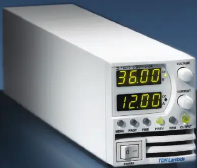
Programmable DC Power Supplies
200W/400W/600W/800W in 2U
Built-in USB, RS-232 & RS-485 Interface
Optional Interface:
LXICompliantLAN
IEEE488.2 SCPI (GPIB) Multi-Drop
Isolated Analog Programming
User Manual
TDK-Lambda

Series
Programmable DC Power Supplies
200W/400W/600W/800W
Built-in USB, RS-232 & RS-485 Interface
USER MANUAL
This Manual Covers Models:
Z10-20 Z20-10 Z36-6 Z60-3.5 Z100-2
Z10-40 Z20-20 Z36-12 Z60-7 Z100-4
Z10-60 Z20-30 Z36-18 Z60-10 Z100-6
Z10-72 Z20-40 Z36-24 Z60-14 Z100-8
Information Concerning Inclusion of Toxic and Hazardous Substances
This information sheet was prepared based on People's Republic of China "Management Methods for Controlling Pollution Caused by Electronic Information Products Regulation" and "SJ/T 11364—2006 Marking for Control of Pollution Caused by Electronic Information Products".
As People's Republic of China "Management Methods for Controlling Pollution Caused by Electronic Information Products Regulation" is a different legislation from EU RoHS2 Directive (2011/65/EU), inquiries concerning EU RoHS2 Directive (2011/65/EU) information should be done separately.
| Date of manufacture | |||
| Part Name | Z^+ Series: Z200, Z400, Z600, Z800 POWER SUPPLY | Product Weight Z200: 1.9Kg | |
| Product Weight Z400: 1.9Kg | |||
| Product Weight Z600: 2.1Kg | |||
| Product Weight Z800: 2.1Kg | |||
| Concentration Values of Toxic and Hazardous Substances/Elements (wt%) Notes | |||||||
| Lead (Pb)0.1wt% | Mercury (Hg)0.1wt% | Cadmium (Cd)0.1wt% | Hexavalent Chromium (Cr6+)0.1wt% | Polybrominated Biphenyls (PBB)0.1wt% | Polybrominated Diphenyl Ethers (PBDE)0.1wt% | ||
| Case O O O O O | |||||||
| Plastic panel O O O O O | |||||||
| PCB's assembly X O O O O | |||||||
| Inner metal parts O O O O O | |||||||
| Inner cables O O O O O O | |||||||
| Accessories O O O O O O | Provided in the package | ||||||
| O: Indicates that the concentration values of toxic and hazardous substances in all "homogeneous materials" of respective parts and materials does not exceed the concentration limits regulated by "SJ/T 11363-2006 Requirements for Concentration Limits for Certain Hazardous Substances in Electronic Information Products".X: Indicates that the concentration value of a toxic or hazardous substance included in a "homogeneous part" of a respective part or material exceeds the concentration limit regulated by "SJ/T 11363-2006 Requirements for Concentration Limits for Certain Hazardous Substances in Electronic Information Products". | |||||||
DECLARATION OF CONFORMITY Z+200, 400, 600 and 800 SERIES
We, TDK-Lambda Ltd., Located at Haharoshet St. 56 Industrial Zone P.O.B. 500 Karmiel, Israel declare under our sole responsibility that the Z200, Z400, Z600 and Z800 SERIES as detailed on the products covered sheet comply with the provisions of the following European Directive and are eligible to bear the CE mark:
Restriction of the use of certain Hazardous Substances Directive 2011/65/EU (RoHS2)
Low Voltage Directive 2006/95/EC
EMC Directive 2004/108/EC
Assurance of conformance of the described product with the provisions of the stated EC Directive is given through compliance to the following standard:
Electrical Safety EN 61010-1: 2010 (3 Edition)
Electromagnetic Compatibility (EMC) EN 61326-1: 2006
Our European Representative in the EU is TDK-Lambda UK Limited, located at Kingsley Avenue, Ilfracombe, Devon, EX34 8ES UK.
| Name of Authorized Signatory | Martin Southam |
| Signature of Authorized Signatory | M SOUTHERS |
| Position of Authorized Signatory | TDK-Lambda EMEAMarketing Director |
| Date: | February 27, 2013 |
| Date Series first CE marked | March 22, 2012 |
| Place where signed | Ilfracombe, Devon, England |
PRODUCTS COVERED SHEETFOR:
Z200, Z400, Z600 and Z800 SERIES
Configuration code: Zxxx-yyyy-o-p, with
xxx=any number between 10 to 100
yyy=any number between 2 to 72
o=blank or any configuration of L, IEEE, IS420, IS510 and/or LAN
p=blank, E, I or U
Table of Contents
REGULATORY NOTICES 11
SAFETY INSTRUCTIONS....11
CHAPTER 1: GENERAL INFORMATION
1.1 User Manual Content 15
1.2 Introduction 15
1.2.1 General Description 15
1.2.2 Models Covered by this Manual.... 15
1.2.3 Features and Options 15
1.2.4 Multiple Output Power System 16
1.2.5 Control via the USB or RS232/485 Communication Ports 16
1.2.6 Analog Voltage Programming and Monitoring 16
1.2.7 Parallel Operation 16
1.2.8 Output Connections 16
1.2.9 Cooling and Mechanical Construction 16
1.3 Accessories.... 17
1.3.1 General 17
1.3.2 Serial Link Cable 17
1.3.3 Misc. Hardware 17
1.3.4 AC Cables 17
1.3.5 Serial Port Cables....17
CHAPTER 2: SPECIFICATIONS
2.1 Z ^+ 200 Series Specifications 18
2.2 Z^+ 400 Series Specifications 22
2.3 Z^+ 600 Series Specifications....26
2.4 Z ^+ 800 Series Specifications....30
2.5 Supplemental Characteristics....33
2.6 Z200W/400W/600W/800W Outline Drawing 34
2.7 Z200W/400W/600W/800W Optional IEEE, Isolated Analog Interface Outline Drawing.....35
2.8 Z200W/400W/600W/800W Front Panel Output Binding Post Outline Drawing .....36
CHAPTER 3: INSTALLATION
3.1 General 37
3.2 Preparation for Use 37
3.3 Initial Inspection 37
3.4 Rack Mounting 37
3.5 Location, Mounting and Cooling....38
3.6 AC Source Requirements 38
3.7 AC Input Power Connection 38
3.7.1 AC Input Connector 38
3.7.2 AC Input Cord 39
3.8 Turn-On Checkout Procedure 39
3.8.1 General 39
3.8.2 Prior to Operation 39
3.8.3 Constant Voltage Check 40
3.8.4 Constant Current Check 40
3.8.5 OVP Check....40
3.8.6 UVL Check 40
3.8.7 Foldback Check 41
3.9 Connecting the Load 41
3.9.1 Load Wiring 41
3.9.2 Current Carrying Capacity 42
3.9.3 Wire Termination 43
3.9.4 Noise and Impedance Effects....43
3.9.5 Inductive Loads 43
3.9.6 Making the Load Connections....43
3.9.7 Connecting Single Loads, Local Sensing (default) 45
3.9.8 Connecting Single Loads, Remote Sensing 45
3.9.9 Connecting Multiple Loads, Radial Distribution Method 46
3.9.10 Multiple Load Connection with Distribution Terminals 46
3.9.11 Grounding Outputs 47
3.10 Local and Remote Sensing....47
3.10.1 Sense Wiring 47
3.10.2 Local Sensing....48
3.10.3 Remote Sensing....48
3.10.4 J2 Sense Connector Technical Information 49
3.11 Repackaging for Shipment 49
CHAPTER 4: FRONT/REAR PANEL CONTROLS AND CONNECTORS
4.1 Introduction....50
4.2 Front Panel Display and Controls 50
4.3 Rear Panel Connectors 52
4.3.1 J1 Connector Terminal and Function 54
4.3.2 J3 Connector Terminal and Function 55
4.4 Front Panel Display Messages 56
4.5 Navigating the Main Menu 57
4.5.1 Introduction....57
4.5.2 Exiting the Main Menu 58
4.6 Navigating Communication Menu 58
4.6.1 Introduction....58
4.6.2 Exiting the Communication Menu 59
4.7 Navigating the Protection Menu 59
4.7.1 Introduction 59
4.7.2 Exiting the Protection Menu....59
CHAPTER 5: LOCAL OPERATION
5.1 Introduction....60
5.2 Standard Operation....60
5.2.1 Constant Voltage Mode and Voltage Setting 60
5.2.2 Constant Current Mode and Current Setting 60
5.2.3 Automatic Crossover....61
5.2.4 Output On/Off Control 61
5.2.5 Safe Start and Auto-Restart Modes....61
5.2.6 Viewing Software Revision....61
5.3 Alarms and Protective Functions....62
5.3.1 Introduction....62
5.3.2 Over Voltage Protection 62
5.3.2.1 Setting the OVP Level 62
5.3.2.2 Resetting the OVP Circuit....63
5.3.3 Under Voltage Protection and Under Voltage Limit 63
5.3.3.1 Setting the UVP/UVL Mode and Level....63
5.3.3.2 Activated UVP Alarm....63
5.3.4 Foldback Protection 63
5.3.4.1 Setting the Foldback Protection....64
5.3.4.2 Activated FOLD Alarm....64
5.3.5 Protection Delay 64
5.3.5.1 Setting the Protection Delay 64
5.3.6 Over Temperature Protection....64
5.3.7 AC Fail Alarm 64
5.4 Series Operation....65
5.4.1 Series Connection for Increased Output Voltage....65
5.4.2 Series Connection for Positive and Negative Output Voltage 65
5.4.3 Remote Programming in Series Operation....66
5.5 Parallel Operation 67
5.5.1 Introduction....67
5.5.2 Basic Parallel Operation....67
5.5.2.1 Master Unit Set Up 67
5.5.2.2 Slave Unit Set Up 68
5.5.2.3 Setting Over Voltage Protection....68
5.5.2.4 Setting Foldback Protection....68
5.5.2.5 Connection to Load....68
5.5.3 Advanced Parallel Operation 70
5.5.3.1 Master Unit Set Up....70
5.5.3.2 Slave Unit Set Up 70
5.6 Daisy-Chain Connection....71
5.7 Rear Panel (J3 Connector) Functions and Settings 71
5.7.1 External Shut Off Function....72
5.7.2 Interlock Function - Analog On/Off. (Enable/Disable) 72
5.7.3 Auxiliary Programmed Function Pin 1 and Pin 2 ....73
5.7.4 Power Supply OK Signal 74
5.8 Rear Panel (J1 Connector) Functions....74
5.8.1 CV/CC Signal 74
5.9 Parameter Setting Memory 75
5.9.1 Default Setting 75
5.9.2 Reset 75
5.9.3 Last Setting Memory 75
5.9.4 Save <1.4> 76
5.9.5 Recall <1..4> 76
CHAPTER 6: REMOTE ANALOG PROGRAMMING
6.1 Introduction....78
6.2 Local/Remote Analog Control....78
6.3 Local/Remote Analog Indication....78
6.4 Remote Voltage Programming of Output Voltage and Current 79
6.5 Remote Resistor Programming of Output Voltage and Output Current 80
6.6 Programming Monitoring of Output Voltage (V_MON) and Current (I_MON) .....81
CHAPTER 7: Serial RS232/RS485 and USB Interface
7.1 Introduction....82
7.2 Configuration....82
7.2.1 Default Setting 82
7.2.2 Address Setting 82
7.2.3 Communication Interface Selection 82
7.2.4 Baud Rate Setting 83
7.2.5 Language Selection (RS232/RS485, USB) 83
7.2.6 Setting Unit in Remote, Local Lockout or Local Mode 83
7.3 Rear Panel RS232/485 Connector 84
7.4 Connectig Power Supply To RS232 Or RS485 BUS....85
7.5 Rear Panel USB Connector 86
7.5.1 USB Getting Started....86
7.6 Multi Power Supply Connection to RS232 Or RS485 or USB 86
7.7 GEN Protocol (GEN series communication language) 87
7.7.1 Data Format 87
7.7.2 End of Message 87
7.7.3 Command Repeat....87
7.7.4 Checksum 87
7.7.5 Acknowledge....87
7.7.6 Backspace 87
7.7.7 Error Messages 87
7.8 GEN Command Set Description 88
7.8.1 General guides 88
7.8.2 Command Set Categories....88
7.8.3 Identification Commands....88
7.8.4 Initialization Commands 89
7.8.5 Output Commands 89
7.8.6 Global Output Commands....91
7.8.7 Auxiliary Commands 93
7.8.8 Status Commands....93
7.9 Serial Communication Test Set-Up....94
7.10 SCPI Protocol 94
7.10.1 Data Format....94
7.10.2 End of Message 94
7.10.3 End of Command 94
7.10.4 Checksum 95
7.10.5 SCPI Requirements 95
7.10.6 SCPI Command Hierarchy 95
7.10.7 Header 95
7.10.8 Data Formats....96
7.10.9 Character Data....96
7.10.10 Commands Notes 96
7.11 SCPI Common Commands....96
7.12 SCPI Subsystem Commands 101
7.12.1 Output Subsystem....101
7.12.2 Instrument Subsystem 104
7.12.3 Voltage Subsystem 104
7.12.4 Current Subsystem....106
7.12.5 Measure Subsystem 107
7.12.6 DISPLAY Subsystem....108
7.12.7 INITiate Subsystem....109
7.12.8 LIST Subsystem 109
7.12.9 STATus Subsystem 111
7.12.10 SYSTem Subsystem 113
7.12.11 TRIGger Subsystem.... 114
7.12.12 WAVE Subsystem 115
7.12.13 Global Subsystem.... 116
7.13 Command Summary.... 117
CHAPTER 8: ADVANCED FUNCTIONS
8.1 Introduction 121
8.2 FIX Mode 121
8.3 LIST Mode 122
8.4 WAVE Mode 123
8.5 Trigger 124
8.5.1 Input Trigger 124
8.5.2 Output Trigger 125
8.6 Transient Waveform Example 125
8.6.1 Wave Programming....125
8.6.2 Wave Execution via Communication PC 125
8.6.3 Wave Execution via Front Panel 126
8.7 Additional Examples 126
8.7.1 List Example 126
8.7.2 Waveform Example 126
CHAPTER 9: STATUS, FAULT AND SRQ REGISTERS
9.1 General 127
9.2 Power Supply Status Structure 128
9.3 Condition Registers 128
9.3.1 Fault Register 128
9.3.2 Status Register....129
9.4 Conditional, Enable and Event Registers 129
9.4.1 Conditional Registers....129
9.4.2 Event Registers....129
9.4.3 Enable Register 129
9.5 Service Request 129
9.6 Standard Event Status Group....130
9.6.1 Register Functions .... 130
9.6.2 Register Commands....130
9.6.3 Status Byte Register 131
9.6.4 Determining the Cause of a Service Interrupt....131
9.6.5 Output Queue....132
9.6.6 Error Messages....132
CHAPTER 10: ISOLATED ANALOG PROGRAMMING OPTION
10.1 Introduction....134
10.2 Specifications 134
10.2.1 0-5V/0-10V Option (PN: IS510)....134
10.2.2 4-20mA Option (PN: IS420) 134
10.3 Isolated Programming & Monitoring Connector 135
10.4 Setup and Operating Instructions 136
10.4.1 Setting Up Power Supply for 0-5/0-10V Isolated Programming and Monitoring.....136
10.4.2 Setting Up Power Supply for 4-20mA Isolated Programming and Monitoring...... 136
CHAPTER 11: MAINTENANCE
11.1 Introduction.... 137
11.2 Units Under Warranty 137
11.3 Periodic Maintenance 137
11.4 Adjustments and Calibration 137
11.5 Parts Replacement and Repairs 137
11.6 Troubleshooting 137
11.7 Fuse Rating....138
USER MANUAL INDEX 141
WARRANTY
This TDK-Lambda product is warranted against defects in materials and workmanship for a period of five years from date of shipment. During the warranty period, TDK-Lambda will, at it's option, either repair or replace products which prove to be defective.
Limitation of Warranty
The warranty shall not apply to defects resulting from improper or inadequate usage or maintenance by the buyer, buyer supplied products or interfacing. The warranty shall not apply to defects resulting from unauthorized modifications or from operation exceeding the environmental specifications of the product or if the QA seal has been removed or altered by anyone other than TDK-Lambda authorised personnel. TDK-Lambda does not warrant the buyers circuitry or malfunctions of TDK-Lambda products resulting from the buyer's circuitry. Furthermore, TDK-Lambda does not warrant any damage occurring as a result of the buyer's circuitry or the buyer's supplied products. No other warranty is expressed or implied.
Warranty Service
This product must be returned to an authorized TDK-Lambda service facility for repairs or other warranty service. For products returned to TDK-Lambda for warranty service, the buyer shall prepay shipping charges to TDK-Lambda and TDK-Lambda shall pay the shipping charges to return the product to the buyer. Refer to section 3.11 for Repackaging for Shipment.
Disclaimer
The information contained in this document is subject to change without notice. TDK-Lambda shall not be liable for errors contained in this document or for incidental or consequential damages in connection with the furnishing, performance or use of this material. No part of this document may be photocopied, reproduced or translated into another language without the prior written consent of TDK-Lambda.
Trademark Information
Microsoft™ and Windows™ are trademarks of Microsoft Corporation.
REGULATORY NOTICES
FCC Notice
This device complies with Part 15 of the FCC Rules. Operation is subject to the following two conditions: (1) this device may not cause harmful interference, and (2) this device must accept any interference received, including interference that may cause undesired operation.
NOTE:
This equipment has been tested and found to comply with the limits for a Class A digital device, pursuant to Part 15 of the FCC rules. These limits are designed to provide reasonable protection against harmful interference when the equipment is operated in a commercial environment. This equipment generates, uses, and can radiate radio frequency energy and, if not installed and used in accordance with the instruction manual, may cause harmful interference to radio communications. Operation of this equipment in a residential area is likely to cause harmful interference in which case the user will be required to correct the interference at his own expense.
WARNING:
Modifications not expressly approved by the party responsible for compliance could void the user's authority to operate the equipment under FCC Rules.
CE NOTICE (European Union)
Marking by the CE Symbol indicates compliance to the Low Voltage Directive (2006/95/EC) of the European Union. Such marking is indicative that the Z^+ series meet the following technical standard: EN 61010-1 - "Electrical Equipment For Measurement, Control and Laboratory Use; Part 1: General Requirements." A "Declaration of Conformity" in accordance with the preceding directives and standards has been made and is on file at our EU representative TDK-Lambda UK, located at Kingsley Avenue, Ilfracombe, Devon EX34 8ES, UK.
SAFETY APPROVALS
UL 61010-1 and CSA-C22.2 No. 61010-1 - UL Listed, C-UL for Canada, IEC/EN 61010-1 - CB/TUV GS. CE marking, when applied to the Z ^+ series, indicates compliance with the Low Voltage Directive 2006/95/EC in that it complies with EN 61010-1.
OTHER
Z200, Z400, Z600, Z800 series are comply with the following Directives:
• RoHS2 Directive (2011/65/EU);
• WEEE Directive (2002/96/EC).
SAFETY INSTRUCTIONS
CAUTION:
The following safety precaution must be observed during all phases of operation, service and repair of this equipment. Failure to comply with the safety precautions or warnings in this document violates safety standards of design, manufacture and intended use of this equipment and may impair the built-in protections within. TDK-Lambda shall not be liable for user's failure to comply with these requirements.
VORSICHT:
Z ^+ series units are not authorized for use as critical component in nuclear control systems, life support systems or equipment for use in hazardous environments without the express written approval of the managing director of TDK-Lambda.
VORSICHT:
The Z^+ series units have been evaluated to Overvoltage category II.
The Z^+ series units are intended for use in the following operation conditions:
* Indoor use
* Pollution degree 2
* Max. operational altitude: 3000m above sea level
* Ambient temperature: 0°C-50°C.
Z^+ series units are Class I product. To minimize electrical shock hazard, the Z^+ series units must be connected to an electrical ground. The instruments must be connected to the AC power supply mains through a standard certified three-wire power cable, with the ground wire firmly connected to an electrical ground (safety ground) at the power outlet. Any interruption of the protective ground conductor or disconnection of the protective earth terminal will cause a potential shock hazard that might cause personal injury.
ERDUNG
Operating personnel must not remove the Z^+ series unit cover.
No internal adjustment or component replacement is allowed by non-TDK-Lambda qualified service personnel. Never replace components with power cable connected. To avoid injuries, always disconnect power, discharge circuits and remove external voltage sources before touching components.
Parts substitutions and modifications are by authorized TDK-Lambda service personnel only. For repairs or modifications, the instrument must be returned to TDK-Lambda service facility.
Do not connect Z^+ series unit to mains supply exceeding the input voltage and frequency rating. The input voltage and frequency rating is: 100-240V\~, 50/60Hz. For safety reasons, the mains supply voltage fluctuations should not exceed +/-10% of nominal voltage.
NETZSTROMEINGANG
The main output of Z^+ series units is capable of providing hazardous energy. Due to hazardous energy level the output and connections therefore must not be user accessible. Manufacturer's final equipment must provide protection to service personnel against inadvertent contact with output bus bars.
Internal fuse is sized for fault protection and if a fuse was opened it would indicate that service is required. Fuse replacement should be made by qualified technical personnel. Refer to maintenance instructions in Chapter 11 for fuse ratings.
SICHERUNG
There is electric shock hazard when the power supply output is adjusted above 42.4V. Ensure that there is no possibility to touch simultaneously one of the output pins and earth (including the power supply's metal enclosure) nor to touch simultaneously one of the output pins and metal parts of any external products supplied by the power supply when the output is adjusted above 42.4V.
WARNUNG:
There is a potential shock hazard when using a power supply with output voltage greater than 42.4V. Do not turn ON power supply when output voltage above 42.4VDC without output bus-bars or output connector protection assembled. Turn OFF power supply or disconnect power supply from AC mains before making or changing any rear panel connection.
WARNUNG:
This user's manual contains the operating instructions, installation instructions and specifications of the Z ^+ Series 200W, 400W, 600W and 800W power supply series. The instructions refer to the standard power supplies, including the built-in USB and RS232/485 serial communication. For information related to operation with the optional LAN and IEEE, refer to User Manual for power supply LAN and IEEE.
1.2 Introduction
1.2.1 General Description
Z ^+ Series power supplies are wide output range, high performance switching power supplies. The Z ^+ Series is power factor corrected and operates from worldwide AC voltage range continuously. Output voltage and current are continuously displayed and LED indicators show the complete operating status of the power supply. The Front Panel controls allow the user to set the output parameters, the protection levels (Over-Voltage protection, Under-Voltage protection and Foldback) and preview the settings. The rear panel includes the necessary connectors to control and monitor the power supply operation by remote analog signals or by the built-in serial communication USB and RS232/485. LAN, IEEE and Isolated-Analog programming/monitoring are optional.
1.2.2 Models Covered by this Manual
| Model Voltage range (V) Current range (A) Model Voltage range (V) Current range (A) |
| Z10-20 0-10 0-20 Z60-3.5 0-60 0-3.5 |
| Z10-40 0-10 0-40 Z60-7 0-60 0-7 |
| Z10-60 0-10 0-60 Z60-10 0-60 0-10 |
| Z10-72 0-10 0-72 Z60-14 0-60 0-14 |
| Z20-10 0-20 0-10 Z100-2 0-100 0-2 |
| Z20-20 0-20 0-20 Z100-4 0-100 0-4 |
| Z20-30 0-20 0-30 Z100-6 0-100 0-6 |
| Z20-40 0-20 0-40 Z100-8 0-100 0-8 |
| Z36-6 0-36 0-6 |
| Z36-12 0-36 0-12 |
| Z36-18 0-36 0-18 |
| Z36-24 0-36 0-24 |
1.2.3 Features and Options
- Constant Voltage / Constant Current with automatic crossover.
• Active Power Factor correction.
• Universal Input Voltage 85-265Vac, continuous operation.
• Embedded Microprocessor Controller.
• Built in USB & RS232/485 Interface.
• Voltage & Current high resolution adjustment by digital Encoders.
• High resolution 16 bit ADCs & DACs.
• Software Calibration (no internal trimmers / potentiometers).
• Last Setting Memory.
• Independent Remote ON/OFF (Opto-Isolated) and Remote Enable/Disable.
• Parallel operation (Master/Slave) with Active current sharing.
• Remote sensing to compensate for voltage drop of power leads.
• External Analog Programming and Monitoring (0-5V or 0-10V, user selectable).
• Cooling fan speed control for low noise and extended fan life. - Optional LAN interface (SCPI compatible).
• Optional IEEE interface (SCPI compatible).
- Optional Isolated Analog programming/monitoring (0-5V or 0-10V, user selectable and 4-20mA).
1.2.4 Multiple Output Power System
The Z^+ Series power supplies series can be configured into a programmable power system of up to 31 units using the built-in USB or RS232/RS485 communication port in the power supply and the RS485 linking cable provided with each power supply.
In a LAN system, each power supply can be controlled using the optional LAN controller (factory installed). In an IEEE system, each power supply can be controlled using the optional IEEE controller (factory installed).
1.2.5 Control via the USB or RS232/485 Communication Ports
The following parameters can be programmed via the serial communication port:
• Output voltage setting.
• Output current setting.
• Output voltage measurement.
• Output current measurement.
• Output on/off control.
• Foldback protection setting.
• Over-voltage protection setting and readback.
• Under-Voltage protection setting and readback.
• Under-Voltage limit setting and read back.
• Power-supply start up mode (last setting or safe mode).
1.2.6 Analog Voltage Programming and Monitoring
Analog inputs and outputs are provided at the rear panel for analog control of the power supply. The output voltage and the current limit can be programmed by analog voltage or by resistor, and can be monitored by analog voltage. The power supply output can be remotely set to On or Off and analog signals monitor the proper operation of the power supply and the mode of operation (CV/CC).
1.2.7 Parallel Operation
Up to six Z^+ Series power supplies of the same output voltage and current rating can be paralleled in master-slave configuration with automatic current sharing to increase available power.
1.2.8 Output Connections
Output connections are made to rear panel bus-bars. Either the positive or negative terminal may be grounded or the output may be floated. Models up to 100VDC rated output shall not float outputs more than +/- 100VDC above/below chassis ground. Contact factory for assistance with higher float voltage applications.
Local or remote sense may be used. In remote sense, the voltage drop on the load wires should be minimized. Refer to the specifications for the maximum voltage drop value.
1.2.9 Cooling and Mechanical Construction
The Z^+ Series is cooled by an internal fan. At installation, care must be taken to allow free air flow into the power supply via the front panel, and out of the power supply via the rear panel. The Z^+ Series power supply is a compact and lightweight unit which allows for easy installation and gives a space saving solution for customer applications.
CAUTION:
Observe all torque guidelines within this manual. Over torque may damage unit or accessories. Such damage is not covered under manufacturers warranty.
1.3 Accessories
1.3.1 General
Accessories are delivered with the power supply or separately upon ordering, The list below shows the possible accessories and ordering numbers.
1.3.2 Serial Link Cable
Serial link cable, for linking power supplies by RS485 communication is provided with the power supply.
Cable description: 0.5m length, shielded, RJ-45 type plugs, 8 contacts (P/N: GEN/RJ45).
1.3.3 Misc. Hardware
- Bus bars protection
- Connector protection
- Connector housing IPD1-06-D-K(SAMTEC)
- Connector housing IPD1-04-D-K(SAMTEC)
- Connector housing IPD1-02-D-K(SAMTEC)
- Contact pins P/N: CC79R-2024-01-L(SAMTEC)
1.3.4 AC Cables
AC cables are not provided with the power supply. If an AC cable is required, it should be ordered according to the following:
Part no. Market Description
| Z-U | USA | 13A 125V, non shielded, 2m typical length, with IEC60320-1, type C15 connector on one end and NEMA-5-15P type plug on the other end. |
| Z-E | Europe | 10A 250V, non shielded, 2m typical length, with IEC60320-1, type C15 connector on one end and IEC60884-1 type plug on the other end. |
| Z-J | Japan | 15A 125V, non shielded, 2m typical length, with IEC60320-1, type C15 connector on one end and Japan JIS C8303 type plug on the other end. |
| Z-GB UK | 10A 250V non shielded, 2m typical length, with IEC60320-1, type C15 connector on one end and UK BS 1363 type plug on the other end. | |
| Z-C | China | 10A 250V, non shielded, 2m typical length, with IEC60320-1, type C15 connector on one end and China GB2099 or GB1002 type plug on the other end. |
| Z-O | GENERAL | 10A 250V, non shielded, 2m typical length, with IEC60320-1, type C15 connector on one end and non-terminated stripped wires on the other end. Use the cable only with plug approved by the national safety standards of the country of usage. |
1.3.5 Serial Port Cables
If a serial port cable is required, it should be ordered according to the description in section 7.2 * USB cables are not provided with the power supply.
2.1 Z ^+ 200 Series Specifications
| MODEL Z 10-20 20-10 36-6 60-3.5 100-2 | ||||||
| 1. Rated output voltage(*1) V 10 20 36 60 100 | ||||||
| 2. Rated output current (*2) A 20 10 6 3.5 2 | ||||||
| 3. Rated output power | W | 200 | 200 | 216 | 210 | 200 |
| CONSTANT VOLTAGE MODE | Z | 10-20 | 20-10 | 36-6 | 60-3.5 | 100-2 | ||
| 1. Max. Line regulation (*6) | --- | 0.01% of rated output voltage+2mV | ||||||
| 2. Max. Load regulation (*7) | --- | 0.01% of rated output voltage+2mV | ||||||
| 3. Ripple and noise (p-p, 20MHz) (*8) mV | 50 50 50 50 | 80 | ||||||
| 4. Ripple r.m.s. 5Hz~1MHz | mV | 5 | 6 | 6 | 7 | 8 | ||
| 5. Temperature coefficient | PPM/°C | 30PPM/°C from rated output voltage, following 30 minutes warm-up. | ||||||
| 6. Temperature stability | --- | 0.02% of rated Vout over 8hrs. interval following 30 minutes warm-up. Constant line, load & temp. | ||||||
| 7. Warm-up drift | --- | Less than 0.05% of rated output voltage+2mV over 30 minutes following power on. | ||||||
| 8. Remote sense compensation/wire | V | 1 | 1 | 2 | 3 | 5 | ||
| 9. Up-prog. Response time, 0--Vomax(*9) | mS | 15 | 30 | 30 | 50 | 50 | ||
| 10. Down-prog. response time: | Full load (*9) | mS | 12 25 30 40 50 | |||||
| Time delay (*17) | 210 | 250 | 320 | 380 | 1200 | |||
| No load (*10) (*15)(*17) | 40 65 85 100 | 250 | ||||||
| No load (*10) (*16)(*17) | 200 | 200 | 290 | 310 | 1100 | |||
| 11. Transient response time | mS | Time for output voltage to recover within 0.5% of its rated output for a load change 10--90% of rated output current. Output set-point: 10~100%, Local sense Less than 1mS, for models up to and including 100V | ||||||
| 12. Hold-up time (*19) | --- | 15mSec Typical | 16mSec Typical | |||||
| CONSTANT CURRENT MODE | Z | 10-20 | 20-10 | 36-6 | 60-3.5 | 100-2 |
| 1. Max. Line regulation (*6) | --- | 0.01% of rated output current+2mA | ||||
| 2. Max. Load regulation (*11) | --- | 0.01% of rated output current+5mA | ||||
| 3. Load regulation thermal drift | --- | Less than 0.05% of rated output current over 30 minutes following load change. | ||||
| 4. Ripple r.m.s. 5Hz~1MHz (*12) | mA | 25 | 15 | 8 | 4 | 3 |
| 5. Temperature coefficient | PPM/°C | 100PPM/°C from rated output current, following 30 minutes warm-up. | ||||
| 6. Temperature stability | --- | 0.05% of rated lout over 8hrs. interval following 30 minutes warm-up. Constant line, load & temperature. | ||||
| 7. Warm-up drift | --- | Less than +/-0.1% of rated output current over 30 minutes following power on. | ||||
| PROTECTIVE FUNCTIONS | Z 10-20 | 20-10 36-6 60-3.5 100-2 | ||||
| 1. Foldback protection | --- | Output shut down when power supply change mode from CV to CC or CC to CV. User presetable. Reset by AC input recycle in autostart mode or by OUTPUT button or by rear panel ENABLE, or by communication port. | ||||
| 2. Over-voltage protection {OVP} | --- | Inverter Shut down method. Reset by AC input recycle in autostart mode or by OUTPUT button or by rear panel ENABLE, or by communication port. | ||||
| 3. Over -voltage trip point | V | 0.5~12 | 1~24 | 2~40 | 5~66 | 5~110 |
| 4. Output under voltage limit (UVL) | --- | Preset by front panel or communication port. Prevents from adjusting Vout below limit. Does not affect in analog programming. | ||||
| 5. Output under voltage protection {UVP} --- | Output shut-down when power supply output voltage goes below UVP programming. User presetable. Reset by AC input recycle in autostart mode or by OUTPUT button or by rear panel ENABLE, or by communication port. | |||||
| 6. Over temperature protection | --- | User selectable, latched or non latched. | ||||
ANALOG PROGRAMMING AND MONITORING
| 1. Vout voltage programming | --- | 0~100%, 0~5V or 0~10V, user selectable. Accuracy and linearity: +/-0.5% of rated Vout. |
| 2. Iout voltage programming (*13) | --- | 0~100%, 0~5V or 0~10V, user selectable. Accuracy and linearity: +/-1% of rated lout. |
| 3. Vout resistor programming | --- | 0~100%, 0~5/10Kohm full scale, user selectable. Accuracy and linearity: +/-1% of rated Vout. |
| 4. Iout resistor programming (*13) | --- | 0~100%, 0~5/10Kohm full scale, user selectable. Accuracy and linearity: +/-1.5% of rated lout. |
| 5. Shut Off (SO) control | --- | By electrical Voltage: 0~0.6V/2~15V or dry contact, user selectable logic. |
| 6. Output current monitor (*13) | --- | 0~5V or 0~10V, user selectable. Accuracy: +/-1%. |
| 7. Output voltage monitor | --- | 0~5V or 0~10V, user selectable. Accuracy: +/-1%. |
| 8. Power supply OK signal | --- | 4~5V-OK, 0V-Fail. 500ohm series resistance. |
| 9. Parallel operation (*20) | --- | Possible, up to 6 units in master/slave mode with single wire current balance connection. |
| 10. Series operation | --- | 2 identical units (with external diodes). |
| 11. CV/CC indicator | --- | Open collector. CC mode: On, CV mode: Off. Maximum voltage: 30V, maximum sink current: 10mA |
| 12. Interlock (ILC) control | --- | Enables/Disables the PS output by dry contact (Short: On, Open: Off, Source current: less than 0.5mA). Ena/Dis is activated by front panel. |
| 13. Local/Remote mode Control | --- | By electrical signal or Open/Short: 0~0.6V or short: Remote, 2~15V or open: Local |
| 14. Local/Remote mode Indicator | --- | Open collector (shunted by 36V zener). On (0~0.6V, 10mA sink current max.) Remote. Off-Local (30V max.). |
| 15.Trigger out | --- | Maximum low level output =0.8V, Minimum high level output =3.8V, Maximum high level output =5V, Maximum source current =16mA, pulse =20μs Typical. |
| 16.Trigger in | --- | Maximum low level input =1.2V, Minimum high level input =3.5V, Maximum high level input =5V, Maximum sink current =16mA, positive edge, trigger: tw =10μs minimum, Tr/Tf =1μs maximum. |
| 17. Programmed signal 1 | --- | Open collector, maximum voltage 25V,maximum sink current 100mA. (Shunted by 27V zener) |
| 18. Programmed signal 2 | --- | Open collector, maximum voltage 25V,maximum sink current 100mA. (Shunted by 27V zener) |
FRONT PANEL
| 1. Control functions | --- | Multiple options with 2 Encoders |
| --- | Vout/lout manual adjust | |
| --- | OVP/UVL/UVP manual adjust | |
| --- | Protection Functions - OVP, UVL,UVP, Foldback, OCP, INT, SO | |
| --- | Communication Functions - Selection of LAN,IEEE,RS232,RS485,USB | |
| --- | Communication Functions - Selection of Baud Rate, Address | |
| --- | Analog Control Functions - Selection Voltage/resistive programming, 5V/10V, 5K/10K programming | |
| --- | Analog Control Functions - Selection of Voltage/Current Monitoring 5V/10V, Output ON/OFF, Front Panel Lock. | |
| 2. Display | --- | Vout: 4 digits, accuracy: 0.5% of rated output voltage+/-1 count. |
| --- | lout: 4 digits, accuracy: 0.5% of rated output current+/-1 count. | |
| 3. Indications | --- | GREEN LEDs: FINE, MENU, PREV, PROT, REM, OUTPUT, CV, CC |
| --- | RED LED: PROT (OVP, UVP, OTP, FOLD, AC FAIL). | |
| 4. Function buttons | --- | FINE, MENU, PREV, PROT, REM, OUTPUT |
PROGRAMMING AND READBACK (RS232/485, USB, Optional: IEEE, LAN)
| 1. Vout programming accuracy | --- | 0.05% of rated output voltage |
| 2. lout programming accuracy (*13) | --- | 0.1% of actual +0.1% of rated output current |
| 3. Vout programming resolution | --- | 0.012% of full scale |
| 4. lout programming resolution | --- | 0.012% of full scale |
| 5. Vout readback accuracy | --- | 0.05% of rated output voltage |
| 6. lout readback accuracy (*13) | --- | 0.1% of actual +0.3% of rated output current |
| 7. Vout readback resolution | --- | 0.012% of full scale |
| 8. lout readback resolution | --- | 0.012% of full scale |
Z ^+ 200 Series Specifications
| INPUT CHARACTERISTICS | 7 10-20 | 20-10 36-6 60-3.5 100-2 | ||||
| 1. Input voltage/freq. (*3) --- 8S~265Vac continuous, 47~63Hz, single phase | ||||||
| 2. Maximum Input current 100/200VAC (*4) (*18) --- 2.65/1.31 2.62/1.29 2.76/1.37 2.69/1.33 2.55/1.26 | ||||||
| 3. Power Factor (Typ) --- >0.99 at 100Vac, >0.98 at 200Vac,100% load | ||||||
| 4. Efficiency (Typ) 100/200VAC (*4) (*18) | % | 76/77.5 | 77/79 | 79/80.5 | 79/80.5 | 79/81 |
| 5. Inrush current 100/200VAC (*5) | --- Less than 15A/30A | |||||
| ENVIRONMENTAL CONDITIONS | ||
| 1. Operating temperature | -- 0~50°C, 100% load. | |
| 2. Storage temperature | -- -20~85°C | |
| 3. Operating humidity | % | 20~90% RH (no condensation). |
| 4. Storage humidity | % | 10~95% RH (no condensation). |
| 5. Altitude | -- | Maximum 3000m. Derate ambient temp above 2000m.Operating: Maximum ambient temperature, From 2000m up to 3000m Ambient temperature 40°C. |
| SAFETY/EMC | |||
| 1. Applicable standards: | Safety | --- | UL61010-1, EN61010-1, IEC61010-1, Design to meet UL60950-1, EN60950-110V≤Vout≤60V: Output,J1,J2,J3,J4,USB,LAN,IEEE/ISOLATED Analog are Non HazardousVout=100V:Output,J1,J2 are Hazardous J3,J4,USB, IEEE/ISOLATED Analog ,LAN are Non Hazardous |
| EMC | --- IEC/EN61326-1 (Built to meet EN55022/EN55024) | ||
| 2. Withstand voltage | --- | 10≤Vout≤36V models: Input-Output&J1,J2,J3,J4,USB,LAN/IEEE/ISOLATED ANALOG: 4242VDC/1min; input-Ground: 2828VDC/1min.Output&J1,J2,J3,J4,USB,LAN/IEEE/ISOLATED ANALOG-Ground: 707VDC/1min.60V,100V models: Input-Output&J1,J2: 4242VDC/1min; Input-J3,J4,USB,LAN/IEEE/ISOLATED Analog: 4242VDC/1min; Input-Ground:2828VDC/1min.Output&J1,J2-J3,J4,USB,LAN/IEEE/ISOLATED ANALOG :1910VDC/1min; Output&J1,J2-Ground: 1380VDC/1min.J3,J4,USB/LAN/IEEE/ISOLATED ANALOG - Ground: 707VDC/1min; | |
| 3. Insulation resistance | --- More than 100Mohm at 25°C, 70%RH. | ||
| 4. Conducted emission | --- IEC/EN61326-1 Industrial Location - B, FCC part 15-B, VCCI-B | ||
| 5. Radiated emission | --- IEC/EN61326-1 Industrial Location - A, FCC part 15-A, VCCI-A | ||
| MECHANICAL | |||
| 1. Cooling | --- Forced air cooling by internal fan. | ||
| 2. Weight | STANDARD | Kg | Less than 1.9Kg.Less than 2.4Kg. Wide body with Isolated analog or Binding post or IEEE. |
| WIDE BODY | Kg | ||
| 3. Dimensions (WxHxD) | STANDARD | mm | H: 83, W: 70, D: 350 (excluding bus bars, handles...). (Refer to Outline drawing).H: 83, W: 105, D: 350 (excluding bus bars, handles...). (Refer to Outline drawing). |
| WIDE BODY | mm | ||
| 4. Vibration | --- According to: IEC60068-2-64 | ||
| 5. Shock | --- Less than 20G, half sine, 11mS. Unit is unpacked. According to: IEC60068-2-27 | ||
NOTES:
*1: Minimum voltage is guaranteed to maximum 0.1% of rated output voltage.
*2: Minimum current is guaranteed to maximum 0.2% of rated output current.
*3: For cases where conformance to various safety standards (UL, IEC, etc...) is required, to be described as 100-240Vac (50/60Hz).
*4: Ta=25°C with rated output power.
*5: Not including EMI filter inrush current, less than 0.2mSec at cold start Ta=25°C
*6: At 85\~132Vac or 170\~265VAC, constant load.
*7: From No-Load to Full-Load, constant input voltage. Measured at the sensing point in Remote Sense.
*8: Measured with JEITA RC-9131A (1:1) probe.
*9: From 10% to 90% or 90% to 10% of Rated Output Voltage, with rated resistive load.
*10: From 90% to 10% of Rated Output Voltage.
*11: For load voltage change, equal to the unit voltage rating, constant input voltage.
*12: For 10V model the ripple is measured at 2V to rated output voltage and rated output current. For other models, the ripple is measured at 10\~100% of rated output voltage and rated output current.
*13: The Constant Current programming, readback and monitoring accuracy do not include the warm-up and Load regulation thermal drift.
*14: Measured with JEITA RC-9131A (1:1) probe.
*15: For cases where the time interval between each down programming is longer than Td (time delay).
*16: For cases where the time interval between each down programming is shorter than Td (time delay).
*17: Td typical Minimum time between consecutive down programming cycles.
*18: PS with Lan, IEEE, models decrease efficiency by 0.5% and increase input current by 0.5%.
PS with Isolated analog option decreases efficiency by 1.5% and increases input current by 1.5%.
*19: At rated output power.
*20: For Parallel operation more than 2 units 5% of total output current is requierd.
2.2 Z ^+ 400 Series Specifications
| MODEL Z 10-40 20-20 36-12 60-7 100-4 | ||||||
| 1. Rated output voltage(*1) V 10 20 36 60 100 | ||||||
| 2. Rated output current (*2) A 40 20 12 7 4 | ||||||
| 3. Rated output power W 400 | 400 | 432 420 | 400 |
| CONSTANT VOLTAGE MODE | Z | 10-40 | 20-20 | 36-12 | 60-7 | 100-4 | ||
| 1. Max. Line regulation (*6) | --- | 0.01% of rated output voltage+2mV | ||||||
| 2. Max. Load regulation (*7) | --- | 0.01% of rated output voltage+2mV | ||||||
| 3. Ripple and noise (p-p, 20MHz) (*8) | mV 50 | 0 50 50 | 80 | |||||
| 4. Ripple r.m.s. 5Hz~1MHz | mV | 5 | 6 | 6 | 7 | 8 | ||
| 5. Temperature coefficient | PPM/°C | 30PPM/°C from rated output voltage, following 30 minutes warm-up. | ||||||
| 6. Temperature stability | --- | 0.02% of rated Vout over 8hrs. interval following 30 minutes warm-up. Constant line, load & temp. | ||||||
| 7. Warm-up drift | --- | Less than 0.05% of rated output voltage+2mV over 30 minutes following power on. | ||||||
| 8. Remote sense compensation/wire | V | 1 | 1 | 2 | 3 | 5 | ||
| 9. Up-prog. Response time, 0~Vomax. (*9) | mS | 15 | 30 | 30 | 50 | 50 | ||
| 10. Down-prog. response time: | Full load (*9) | mS | 10 10 15 30 | 50 | ||||
| Time delay (*17) | 210 | 250 320 380 | 1200 | |||||
| No load (*10) (*15) (*17) | 40 | 65 | 85 | 100 | 250 | |||
| No load (*10) (*16) (*17) | 200 | 200 | 290 | 310 | 1100 | |||
| 11. Transient response time | mS | Time for output voltage to recover within 0.5% of its rated output for a load change 10~90% of rated output current. Output set-point: 10~100%, Local sense. Less than 1mS, for models up to and including 100V | ||||||
| 12. Hold-up time (*19) | --- | 15mSec Typical. | 16mSec Typical. | |||||
| CONSTANT CURRENT MODE | Z | 10-40 | 20-20 | 36-12 | 60-7 | 100-4 |
| 1. Max. Line regulation (*6) | --- | 0.01% of rated output current +2mA | ||||
| 2. Max. Load regulation (*11) | --- | 0.01% of rated output current +5mA | ||||
| 3. Load regulation thermal drift | --- | Less than 0.05% of rated output current over 30 minutes following load change. | ||||
| 4. Ripple r.m.s. 5Hz~1MHz (*12) | mA | 70 | 40 | 15 | 8 | 3 |
| 5. Temperature coefficient | PPM/°C | 100PPM/°C from rated output current, following 30 minutes warm-up. | ||||
| 6. Temperature stability | --- | 0.05% of rated lout over 8hrs. interval following 30 minutes warm-up. Constant line, load & temperature. | ||||
| 7. Warm-up drift | --- | Less than +/-0.1% of rated output current over 30 minutes following power on. | ||||
| PROTECTIVE FUNCTIONS | Z 10-40 | 20-20 36-12 60-7 100-4 | ||||
| 1. Foldback protection | --- | Output shut-down when power supply change mode from CV to CC or CC to CV. User presetable. Reset by AC input recycle in autostart mode or by OUTPUT button or by rear panel ENABLE, or by communication port. | ||||
| 2. Over-voltage protection {OVP} | --- | Inverter Shut down method. Reset by AC input recycle in autostart mode or by OUTPUT button or by rear panel ENABLE, or by communication port. | ||||
| 3. Over - voltage trip point | V | 0.5~12 | 1~24 | 2~40 | 5~66 | 5~110 |
| 4. Output under voltage limit (UVL) | --- | Preset by front panel or communication port. Prevents from adjusting Vout below limit. Does not affect in analog programming. | ||||
| 5. Output under voltage protection {UVP} --- | Output shut-down when power supply output voltage goes below UVP programming. User presetable. Reset by AC input recycle in autostart mode or by OUTPUT button or by rear panel ENABLE, or by communication port. | |||||
| 6. Over temperature protection | --- | User Selectable. Latched or non latched | ||||
ANALOG PROGRAMMING AND MONITORING
| 1. Vout voltage programming | --- | 0~100%, 0~5V or 0~10V, user selectable. Accuracy and linearity: +/-0.5% of rated Vout. |
| 2. Iout voltage programming (*13) | --- | 0~100%, 0~5V or 0~10V, user selectable. Accuracy and linearity: +/-1% of rated lout. |
| 3. Vout resistor programming | --- | 0~100%, 0~5/10Kohm full scale, user selectable. Accuracy and linearity: +/-1% of rated Vout. |
| 4. Iout resistor programming (*13) | --- | 0~100%, 0~5/10Kohm full scale, user selectable. Accuracy and linearity: +/-1.5% of rated lout. |
| 5. Shut Off (SO) control | --- | By electrical Voltage: 0~0.6V/2~15V or dry contact, user selectable logic. |
| 6. Output current monitor (*13) | --- | 0~5V or 0~10V, user selectable. Accuracy: +/-1%. |
| 7. Output voltage monitor | --- | 0~5V or 0~10V, user selectable. Accuracy: +/-1%. |
| 8. Power supply OK signal | --- | 4~5V-OK, 0V-Fail. 500ohm series resistance. |
| 9. Parallel operation (*21) | --- | Possible, up to 6 units in master/slave mode with single wire current balance connection. |
| 10. Series operation | --- | 2 identical units (with external diodes). |
| 11. CV/CC indicator | --- | Open collector. CC mode: On, CV mode: Off. Maximum voltage: 30V, maximum sink current: 10mA |
| 12. Interlock (ILC) control | --- | Enables/Disables the PS output by dry contact (Short: On, Open: Off, Source current: less than 0.5mA). Ena/Dis is activated by front panel. |
| 13. Local/Remote mode Control | --- | By electrical signal or Open/Short: 0~0.6V or short: Remote, 2~15V or open: Local |
| 14. Local/Remote mode Indicator | --- | Open collector (shunted by 36V zener). On (0~0.6V, 10mA sink current max.)-Remote. Off-Local (30V max.). |
| 15. Trigger out | --- | Maximum low level output =0.8V, Minimum high level output =3.8V, Maximum high level output =5V, Maximum source current =16mA, pulse =20μs Typical. |
| 16. Trigger in | --- | Maximum low level input =1.2V, Minimum high level input =3.5V, Maximum high level input =5V, Maximum sink current =16mA, positive edge, trigger: tw =10μs minimum, Tr/Tf =1μs maximum. |
| 17. Programmed signal 1 | --- | Open collector, maximum voltage 25V, maximum sink current 100mA. (Shunted by 27V zener) |
| 18. Programmed signal 2 | --- | Open collector, maximum voltage 25V, maximum sink current 100mA. (Shunted by 27V zener) |
FRONT PANEL
| 1. Control functions | --- | Multiple options with 2 Encoders |
| --- | Vout/lout manual adjust | |
| --- | OVP/UVL /UVP manual adjust | |
| --- | Protection Functions - OVP, UVL, UVP, Foldback, OCP, INT, SO | |
| --- | Communication Functions - Selection of LAN,IEEE (*20), R5232,RS485,USB | |
| --- | Communication Functions - Selection of Baud Rate, Address | |
| --- | Analog Control Functions - Selection Voltage/resistive programming, 5V/10V, 5K/10K programming | |
| --- | Analog Control Functions - Selection of Voltage/Current Monitoring 5V/10V, Output ON/OFF, Front Panel Lock. | |
| 2. Display | --- | Vout: 4 digits, accuracy: 0.5% of rated output voltage+/-1 count. |
| --- | lout: 4 digits, accuracy: 0.5% of rated output current+/-1 count. | |
| 3. Indications | --- | GREEN LEDs: FINE, MENU, PREV, PROT, REM, OUTPUT, CV, CC |
| --- | RED LED: PROT (OVP, UVP, OTP, FOLD, AC FAIL). | |
| 4. Function buttons | --- | FINE, MENU, PREV, PROT, REM, OUTPUT |
PROGRAMMING AND READBACK (RS232/485,USB, Optional: IEEE(*20), LAN)
| 1. Vout programming accuracy | --- | 0.05% of rated output voltage |
| 2. lout programming accuracy (*13) | --- | 0.1% of actual +0.1% of rated output current |
| 3. Vout programming resolution | --- | 0.012% of full scale |
| 4. lout programming resolution | --- | 0.012% of full scale |
| 5. Vout readback accuracy | --- | 0.05% of rated output voltage |
| 6. lout readback accuracy (*13) | --- | 0.1% of actual +0.3% of rated output current |
| 7. Vout readback resolution | --- | 0.012% of full scale |
| 8. lout readback resolution | --- | 0.012% of full scale |
Z ^+ 400 Series Specifications
| INPUT CHARACTERISTICS Z 10-40 20-20 36-12 60-7 | 100-4 | |||||
| 1. Input voltage/freq. (*3) --- 85~265Vac continuous, 47~63Hz, single phase | ||||||
| 2. Maximum Input current 100/200VAC (*4) (*18) --- 5.05/2.47 4.98/2.45 5.25/2.57 5.10/2.50 4.80/2.37 | ||||||
| 3. Power Factor {Typ} --- 0.99 at 100/200Vac, 100% load | ||||||
| 4. Efficiency {Typ} 100/200VAC (*4) (*18) | % | 80/82 | 81/83 | 83/85 | 83/85 | 84/86 |
| 5. Inrush current (*5) | --- Less than 25A | |||||
| ENVIRONMENTAL CONDITIONS | ||
| 1. Operating temperature | -- 0~50°C, 100% load. | |
| 2. Storage temperature | -- -20~85°C | |
| 3. Operating humidity | % | 20~90% RH (no condensation). |
| 4. Storage humidity | % | 10~95% RH (no condensation). |
| 5. Altitude | -- | Maximum 3000m. Derate ambient temp above 2000m.Operating: Maximum ambient temperature, From 2000m up to 3000m Ambient temperature 40°C. |
| SAFETY/EMC | |||
| 1. Applicable standards: | Safety | --- | UL61010-1, EN61010-1, IEC61010-1, Design to meet UL60950-1, EN60950-110V≤Vout≤60V: Output,J1,J2,J3,J4,USB,LAN,IEEE/ISOLATED Analog are Non HazardousVout=100V:Output,J1,J2 are Hazardous J3,J4,USB, IEEE/ISOLATED Analog ,LAN are Non Hazardous |
| EMC | --- IEC/ | EN61326-1 (Built to meet EN55022/EN55024) | |
| 2. Withstand voltage | --- | 10≤Vout≤36V models: Input-Output&J1,J2,J3,J4,USB,LAN/IEEE/ISOLATED ANALOG: 4242VDC/1min; Input-Ground: 2828VDC/1min.Output&J1,J2,J3,J4,USB,LAN/IEEE/ISOLATED ANALOG-Ground: 707VDC/1min.60V,100V models: Input-Output&J1,J2: 4242VDC/1min; Input-J3,J4,USB,LAN/IEEE/ISOLATED Analog: 4242VDC/1min; Input-Ground:2828VDC/1min.Output&J1,J2-J3,J4,USB,LAN/IEEE/ISOLATED ANALOG :1910VDC/1min; Output&J1,J2-Ground: 1380VDC/1min.J3,J4,USB/LAN/IEEE/ISOLATED ANALOG - Ground: 707VDC/1min; | |
| 3. Insulation resistance | --- More than 100Mohm at 25°C, 70%RH. | ||
| 4. Conducted emission | --- IEC/ | EN61326-1 Industrial Location - B, FCC part 15-B, VCCI-B | |
| 5. Radiated emission | --- IEC/ | EN61326-1 Industrial Location - A, FCC part 15-A, VCCI-A | |
| MECHANICAL | |||
| 1. Cooling | --- Forced air cooling by internal fan | ||
| 2. Weight | STANDARD | Kg Less than 1.9Kg. | |
| WIDE BODY | Kg | Less than 2.4Kg. Wide body with Isolated analog or Binding post or IEEE | |
| 3. Dimensions (WxHxD) | STANDARD | mm | H: 83, W: 70, D: 350 (excluding bus bars, handles...). (Refer to Outline drawing) |
| WIDE BODY | mm | H: 83, W: 105, D: 350 (excluding bus bars, handles...). (Refer to Outline drawing) | |
| 4. Vibration | --- According to: IEC60068-2-64 | ||
| 5. Shock | --- Less than 20G, half sine, 11mS. Unit is unpacked. According to: IEC60068-2-27 | ||
NOTES:
*1: Minimum voltage is guaranteed to maximum 0.1% of rated output voltage.
*2: Minimum current is guaranteed to maximum 0.2% of rated output current.
*3: For cases where conformance to various safety standards (UL, IÉC, etc...) is required, to be described as 100-240Vac (50/60Hz).
*4: Ta=25°C with rated output power.
*5: Not including EMI filter inrush current, less than 0.2mSec.
*6: At 85\~132Vac or 170\~265VAC, constant load.
*7: From No-Load to Full-Load, constant input voltage. Measured at the sensing point in Remote Sense.
*8: Measured with JEITA RC-9131A (1:1) probe.
*9: From 10% to 90% or 90% to 10% of Rated Output Voltage, with rated resistive load.
*10: From 90% to 10% of Rated Output Voltage.
*11: For load voltage change, equal to the unit voltage rating, constant input voltage.
*12: For 10V model the ripple is measured at 2V to rated output voltage and rated output current. For other models, the ripple is measured at 10\~100% of rated output voltage and rated output current.
*13: The Constant Current programming, readback and monitoring accuracy do not include the warm-up and Load regulation thermal drift.
*14: Measured with JEITA RC-9131A (1:1) probe.
*15: For cases where the time interval between each down programming is longer than Td (time delay).
*16: For cases where the time interval between each down programming is shorter than Td (Time delay).
*17: Td typical Minimum time between consecutive down programming cycles.
*18: PS with Lan, IEEE, models decrease efficiency by 0.25% and increase input current by 0.25%.
PS with Isolated analog option decreases efficiency by 0.75% and increases input current by 0.75%.
*19: At rated output power.
*20: Max. ambient temperature for using IEEE is 45°C
*21: For Parallel operation more than 2 units 5% of total output current is requierd.
2.3 Z+600 Series Specifications
| MODEL Z 10-60 20-30 36-18 60-10 100-6 | ||||||
| 1. Rated output voltage(*1) V 10 20 36 60 100 | ||||||
| 2. Rated output current (*2) A 60 30 18 10 6 | ||||||
| 3. Rated output power W 600 600 648 600 600 |
| CONSTANT VOLTAGE MODE Z 10-60 20-30 36-18 60-10 | 100-6 | |||||||
| 1. Max. Line regulation (*6) | --- | 0.01% of rated output voltage+2mV | ||||||
| 2. Max. Load regulation (*7) | --- | 0.01% of rated output voltage+2mV | ||||||
| 3. Ripple and noise (p-p, 20MHz) (*8) mV 50 50 50 50 80 | ||||||||
| 4. Ripple r.m.s. 5Hz~1MHz | mV | 5 | 5 | 5 | 12 | 15 | ||
| 5. Temperature coefficient | PPM/°C | 30PPM/°C from rated output voltage, following 30 minutes warm-up. | ||||||
| 6. Temperature stability | --- | 0.05% of rated Vout over 8hrs. interval following 30 minutes warm-up. Constant line, load & temp. | ||||||
| 7. Warm-up drift | --- | Less than 0.05% of rated output voltage+2mV over 30 minutes following power on. | ||||||
| 8. Remote sense compensation/wire | V | 1 | 1 | 2 | 3 | 5 | ||
| 9. Up-prog. Response time, 0~Vomax.(*)9) | mS 50 50 50 100 | |||||||
| 10. Down-prog. response time: | Full load (*9) | 50 570 ms | 25 25 25 25 80 | |||||
| Time delay (*17) 285 425 450*17) | 1370 | |||||||
| No load (*10) (*15)(*)17) | 65 110 155 173 375 | |||||||
| No load (*10) (*16)(*)17) | 280 470 470 500 | 1200 | ||||||
| 11. Transient response time | mS | Time for output voltage to recover within 0.5% of its rated output for a load change 10~90% of rated output current. Output set point: 10~100%, Local sense. Less than 1mS, for models up to and Including 100V | ||||||
| 12. Hold-up time (*18) | --- | 1SmSec Typical. | 20mSec Typical. | |||||
| CONSTANT CURRENT MODE | Z 10-60 | 20-30 36-18 60-10 100-6 | ||||
| 1. Max. Line regulation (*6) | --- | 0.01% of rated output current=2mA | ||||
| 2. Max. Load regulation (*11) | --- | 0.01% of rated output current=5mA | ||||
| 3. Load regulation thermal drift | --- | Less than 0.15% of rated output current over 30 minutes following load change. | ||||
| 4. Ripple r.m.s. 5Hz~1MHz (*12) | mA | 150 | 75 | 25 | 8 | 5 |
| 5. Temperature coefficient | PPM/°C | 100PPM/°C from rated output current, following 30 minutes warm-up. | ||||
| 6. Temperature stability | --- | 0.05% of rated lout over 8hrs. interval following 30 minutes warm-up. Constant line, load & temperature. | ||||
| 7. Warm-up drift | --- | 10V Model: Less than +/-0.3% of rated output current over 30 minutes following power on.20V, 36V Model: Less than +/-0.15% of rated output current over 30 minutes following power on.60V, 100V Models: Less than +/-0.1% of rated output current over 30 minutes following power on. | ||||
| PROTECTIVE FUNCTIONS | Z 10-60 | 20-30 36-18 60-10 100-6 | ||||
| 1. Foldback protection | — | Output shut-down when power supply change mode from CV to CC or CC to CV. User presetable. Reset by AC input recycle in autostart mode or by OUTPUT button or by rear panel ENABLE, or by communication port. | ||||
| 2. Over-voltage protection (OVP) | — | Inverter Shut down method. Reset by AC input recycle in autostart mode or by OUTPUT button or by rear panel ENABLE, or by communication port. | ||||
| 3. Over -voltage trip point | V | 0.5~12 | 1~24 | 2~40 | 5~66 | 5~110 |
| 4. Output under voltage limit (UVL) | — | Preset by front panel or communication port. Prevents from adjusting Vout below limit. Does not affect in analog programming. | ||||
| 5. Output under voltage protection (UVP) | — | Output shut-down when power supply output voltage goes below UVP programming. User presetable. Reset by AC input recycle in autostart mode or by OUTPUT button or by rear panel ENABLE, or by communication port. | ||||
| 6. Over temperature protection | — | User Selectable. Latched or non latched. | ||||
ANALOG PROGRAMMING AND MONITORING
| 1. Vout voltage programming | --- | 0~100%, 0~5V or 0~10V, user selectable. Accuracy and linearity: +/-0.5% of rated Vout. |
| 2. Iout voltage programming (*13) | --- | 0~100%, 0~5V or 0~10V, user selectable. Accuracy and linearity: +/-1% of rated Iout. |
| 3. Vout resistor programming | --- | 0~100%, 0~5/10Kohm full scale, user selectable. Accuracy and linearity: +/-1% of rated Vout. |
| 4. Iout resistor programming (*13) | --- | 0~100%, 0~5/10Kohm full scale, user selectable. Accuracy and linearity: +/-1.5% of rated Iout. |
| 5. Shut Off (SO) control | --- | By electrical Voltage: 0~0.6V/2~15V or dry contact, user selectable logic. |
| 6. Output current monitor (*13) | --- | 0~5V or 0~10V, user selectable. Accuracy: +/-1%. |
| 7. Output voltage monitor | --- | 0~5V or 0~10V, user selectable. Accuracy: +/-1%. |
| 8. Power supply OK signal | --- | 4~5V-OK, 0V-Fail. 500ohm series resistance. |
| 9. Parallel operation (*20) | --- | Possible, up to 6 units in master/slave mode with single wire current balance connection. |
| 10. Series operation | --- | 2 identical units (with external diodes). |
| 11. CV/CC indicator | --- | Open collector. CC mode: On, CV mode: Off. Maximum voltage: 30V, maximum sink current: 10mA |
| 12. Interlock (ILC) control | --- | Enables/Disables the PS output by dry contact (Short: On, Open: Off, Source current: less than 0.5mA). Ena/Dis is activated by front panel. |
| 13. Local/Remote mode Control | --- | By electrical signal or Open/Short: 0~0.6V or short: Remote, 2~15V or open: Local |
| 14. Local/Remote mode Indicator | --- | Open collector (shunted by 36V zener). On (0~0.6V, 10mA sink current max.) Remote. Off Local (30V max.). |
| 15.Trigger out | --- | Maximum low level output =0.8V, Minimum high level output =3.8V, Maximum high level output =5V, Maximum source current =16mA, pulse =20μs Typical. |
| 16.Trigger in | --- | Maximum low level input =1.2V, Minimum high level input =3.5V, Maximum high level input =5V, Maximum sink current =16mA, positive edge, trigger: tw =10μs minimum, Tr/Tf =1μs maximum. |
| 17. Programmed signal 1 | --- | Open collector, maximum voltage 25V, maximum sink current 100mA. (Shunted by 27V zener) |
| 18. Programmed signal 2 | --- | Open collector, maximum voltage 25V, maximum sink current 100mA. (Shunted by 27V zener) |
FRONT PANEL
| 1. Control functions | --- | Multiple options with 2 Encoders |
| --- | Vout/lout manual adjust | |
| --- | OVP/UVL /UVP manual adjust | |
| --- | Protection Functions - OVP, UVL, UVP, Foldback, OCP, INT, SO | |
| --- | Communication Functions - Selection of LAN,IEEE (*19), RS232,RS485,USB | |
| --- | Communication Functions - Selection of Baud Rate, Address | |
| --- | Analog Control Functions - Selection Voltage/resistive programming, 5V/10V, 5K/10K programming | |
| --- | Analog Control Functions - Selection of Voltage/Current Monitoring 5V/10V, Output ON/OFF, Front Panel Lock. | |
| 2. Display | --- | Vout: 4 digits, accuracy: 0.5% of rated output voltage+/-1 count. |
| --- | lout: 4 digits, accuracy: 0.5% of rated output current+/-1 count. | |
| 3. Indications | --- | GREEN LEDs: FINE, MENU, PREV, PROT, REM, OUTPUT, CV, CC |
| --- | RED LED: PROT (OVP, UVP, OTP, FOLD, AC FAIL). | |
| 4. Function buttons | --- | FINE, MENU, PREV, PROT, REM, OUTPUT |
PROGRAMMING AND READBACK (RS232/485,USB, Optional: IEEE(*19), LAN)
| 1. Vout programming accuracy | --- | 0.05% of rated output voltage |
| 2. lout programming accuracy (*13) | --- | 0.1% of actual +0.1% of rated output current |
| 3. Vout programming resolution | --- | 0.012% of full scale |
| 4. lout programming resolution | --- | 0.012% of full scale |
| 5. Vout readback accuracy | --- | 0.05% of rated output voltage |
| 6. lout readback accuracy (*13) | --- | 0.1% of actual +0.3% of rated output current |
| 7. Vout readback resolution --- 0.012% of full scale | ||
| 8. lout readback resolution | --- | 0.012% of full scale |
Z ^+ 600 Series Specifications
| INPUT CHARACTERISTICS | 7 | 10-60 20-30 36-18 60-10 100-6 | |||
| 1. Input voltage/freq. (*3) --- 85~265Vac continuous, 47~63Hz, single phase | |||||
| 2. Maximum Input current 100/200VAC (*4) --- 7.48/3.69 7.22/3.56 7.70/3.80 7.13/3.52 7.13/3.52 | |||||
| 3. Power Factor (Typ) --- 0.99 at 100, 0.98 at 200Vac, 100% load | |||||
| 4. Efficiency (Typ) 100/200VAC (*4) % 81/83 84/86 85/87 85/87 85/87 | |||||
| 5. Inrush current (*5) --- Less than 30A | |||||
| ENVIRONMENTAL CONDITIONS | ||
| 1. Operating temperature --- 0~50°C, 100% load. | ||
| 2. Storage temperature | --- -20~85°C | |
| 3. Operating humidity | % | 20~90% RH (no condensation). |
| 4. Storage humidity | % | 10~95% RH (no condensation). |
| 5. Altitude | -- | Maximum 3000m. Derate ambient temp above 2000m.Operating: Maximum ambient temperature, From 2000m up to 3000m Ambient temperature 40°C. |
| SAFETY/EMC | |||
| 1. Applicable standards: | Safety | --- | UL61010-1, EN61010-1, IEC61010-1, Design to meet UL60950-1, EN60950-110V≤Vout≤60V: Output,J1,J2,J3,J4,USB,LAN,IEEE/ISOLATED Analog are Non HazardousVout=100V:Output,J1,J2 are Hazardous J3,J4,USB, IEEE/ISOLATED Analog ,LAN are Non Hazardous |
| EMC | --- IEC/ | EN61326-1 (Built to meet EN55022/EN55024) | |
| 2. Withstand voltage | --- | 10Vout36V models: Input-Output&J1, J2, J3, J4, USB, LAN/IEEE/ISOLATED ANALOG: 4242VDC/1min; Input-Ground: 2828VDC/1min.Output&J1, J2, J3, J4, USB, LAN/IEEE/ISOLATED ANALOG-Ground: 707VDC/1min.60V,100V models: Input-Output&J1,J2: 4242VDC/1min; Input-J3,J4,USB, LAN/IEEE/ISOLATED Analog: 4242VDC/1min; Input-Ground: 2828VDC/1min.Output&J1, J2- J3, J4, USB, LAN/IEEE/ISOLATED ANALOG: 1910VDC/1min; Output&J1, J2-Ground: 1380VDC/1min.J3, J4, USB/LAN/IEEE/ISOLATED ANALOG - Ground: 707VDC/1min; | |
| 3. Insulation resistance | --- More than 100Mohm at 25°C, 70%RH. | ||
| 4. Conducted emission | --- IEC/ | EN61326-1 Industrial Location - B, FCC part 15-B, VCCI-B | |
| 5. Radiated emission | --- IEC/ | EN61326-1 Industrial Location - A, FCC part 15-A, VCCI-A | |
| MECHANICAL | |||
| 1. Cooling | --- Forced air cooling by internal fan. | ||
| 2. Weight | STANDARD | Kg | Less than 2.1Kg.Less than 2.6Kg. Wide body with Isolated analog or Binding post or IEEE. |
| WIDE BODY | Kg | ||
| 3. Dimensions (WxHxD) | STANDARD | mm | H: 83, W: 70, D: 350 (excluding bus bars, handles...). (Refer to Outline drawing)H: 83, W: 105, D: 350 (excluding bus bars, handles...). (Refer to Outline drawing) |
| WIDE BODY | mm | ||
| 4. Vibration | --- According to: IEC60068-2-64 | ||
| 5. Shock | --- Less than 20G, half sine, 11mS. Unit is unpacked. According to: IEC60068-2-27 | ||
NOTES:
*1: Minimum voltage is guaranteed to maximum 0.1% of rated output voltage.
*2: Minimum current is guaranteed to maximum 0.2% of rated output current.
*3: For cases where conformance to various safety standards (UL, IEC, etc...) is required, to be described as 100-240Vac (50/60Hz).
*4: Ta=25C with rated output power.
*5: Not including EMI filter inrush current, less than 0.2mSec.
*6: At 85\~132Vac or 170\~265VAC, constant load
*7: From No-Load to Full-Load, constant input voltage. Measured at the sensing point in Remote Sense.
*8: Measured with JEITA RC-9131A (1:1) probe
*9: From 10% to 90% or 90% to 10% of Rated output Voltage, with rated resistive load.
*10: From 90% to 10% of Rated output Voltage.
*11: For load voltage change, equal to the unit voltage rating, constant input voltage.
*12: For 10V model the ripple is measured at 2V to rated output voltage and rated output current. For other models, the ripple is measured at 10\~100% of rated output voltage and rated output current.
*13: The Constant Current programming, readback and monitoring accuracy do not include the warm-up and Load regulation thermal drift.
*14: Measured with JEITA RC-9131A (1:1) probe.
*15: For cases where the time interval between each down programming is longer than Td (time delay).
*16: For cases where the time interval between each down programming is shorter than Td (time delay).
*17: Td typical Minimum time between consecutive down programming cycles.
*18: At rated output power.
*19: Max. ambient temperature for using IEEE is 45°C
*20: For Parallel operation more than 2 units 5% of total output current is required.
2.4 Z ^+ 800 Series Specifications
| MODEL Z 10-72 20-40 36-24 60-14 100-8 | |||||||||
| 1. Rated output voltage(*1) V 10 20 36 60 100 | |||||||||
| 2. Rated output current (*2)(*21) | Vin ≥ 100Vac, Ta ≤ 50°C A 72 40 24 14 8 | ||||||||
| 85Vac ≤ Vin < 100Vac, Ta ≤ 40°C A 72 40 24 14 8 | |||||||||
| 85Vac ≤ Vin < 100Vac, 40°C < Ta ≤ 50°C | A 66 36 20 12.5 | 7.5 | |||||||
| 3. Rated output power | Vin ≥ 100Vac, Ta ≤ 50°C | W | 720 | 800 | 864 | 840 | 800 | ||
| 85Vac ≤ Vin < 100Vac, Ta ≤ 40°C | W | 720 | 800 | 864 | 840 | 800 | |||
| 85Vac ≤ Vin < 100Vac, 40°C < Ta ≤ 50°C | W | 660 | 720 720 750 | 750 | |||||
| CONSTANT VOLTAGE MODE | Z 10-72 20-40 36-24 60-14 100-8 | ||||||||
| 1. Max. Line regulation (*6) | — | 0.01% of rated output voltage+2mV | |||||||
| 2. Max. Load regulation (*7) | — | 0.01% of rated output voltage+2mV | |||||||
| 3. Ripple and noise (p-p, 20MHz) (*8) | mV | 50 | 50 | 50 | 60 | 80 | |||
| 4. Ripple r.m.s. 5Hz~1MHz | mV | 5 | 5 | 5 | 12 | 15 | |||
| 5. Temperature coefficient | PPM/°C | 30PPM/°C from rated output voltage, following 30 minutes warm-up. | |||||||
| 6. Temperature stability | — | 0.05% of rated Vout over 8hrs. interval following 30 minutes warm-up. Constant line, load & temp. | |||||||
| 7. Warm-up drift | — | Less than 0.05% of rated output voltage+2mV over 30 minutes following power on. | |||||||
| 8. Remote sense compensation/wire | V | 1 | 1 | 2 | 3 | 5 | |||
| 9. Up-prog. Response time, 0-Vomax.(*9) mS | 50 50 50 50 100 | ||||||||
| 10. Down-prog. response time: | Full load (*9) | mS | 25 25 25 25 | 80 | |||||
| Time delay (*17) | 285 | 425 450 570 | 1370 | ||||||
| No load (*10) (*15) (*17) | 65 110 155 175 | 375 | |||||||
| No load (*10) (*16) (*17) | 280 | 470 | 470 | 500 | 1200 | ||||
| 11. Transient response time | mS | Time for output voltage to recover within 0.5% of its rated output for a load change 10~90% of rated output current. Output set-point: 10~100%, Local sense. Less than 1mS, for models up to and including 100V | |||||||
| 12. Hold-up time (*18) | — | 10mSec Typical. Rated output power. | |||||||
| CONSTANT CURRENT MODE | Z 10-72 20-40 36-24 60-14 100-8 | ||||||||
| 1. Max. Line regulation (*6) | — | 0.01% of rated output current+2mA | |||||||
| 2. Max. Load regulation (*11) | — | 0.01% of rated output current+5mA | |||||||
| 3. Load regulation thermal drift | — | For 10V: Less than 0.15% of rated output current over 30 minutes following load change. For 20V ~ 100V: Less than 0.1% of rated output current over 30 minutes following load change. | |||||||
| 4. Ripple r.m.s. 5Hz~1MHz (*12) | mA | 180 | 100 | 31 | 28 | 12 | |||
| 5. Temperature coefficient | PPM/°C | 100PPM/°C from rated output current, following 30 minutes warm-up. | |||||||
| 6. Temperature stability | — | 0.05% of rated lout over 8hrs. interval following 30 minutes warm-up. Constant line, load & temperature. | |||||||
| 7. Warm-up drift | — | 10V model: Less than +/-0.3%, 20V model: Less than +/-0.15%, 36V~100 models: Less than +/-0.1% of rated output current over 30 minutes following power on. | |||||||
| PROTECTIVE FUNCTIONS | Z 10-72 20-40 36-24 60-14 100-8 | ||||||||
| 1. Foldback protection | — | Output shut-down when power supply change mode from CV to CC or CC to CV. User presetable. Reset by AC input recycle in autostart mode or by OUTPUT button or by rear panel ENABLE, or by communication port. | |||||||
| 2. Over-voltage protection (OVP) | — | Inverter Shut down method. Reset by AC input recycle in autostart mode or by OUTPUT button or by rear panel ENABLE, or by communication port. | |||||||
| 3. Over - voltage trip point | V | 0.5-12 | 1-24 | 2-40 | 5-66 | 5-110 | |||
| 4. Output under voltage limit (UVL) | — | Preset by front panel or communication port. Prevents from adjusting Vout below limit. Does not affect in analog programming. | |||||||
| 5. Output under voltage protection (UVP) — | Output shut-down when power supply output voltage goes below UVP programming. User presetable. Reset by AC input recycle in autostart mode or by OUTPUT button or by rear panel ENABLE, or by communication port. | ||||||||
| 6. Over temperature protection | — | User Selectable. Latched or non latched | |||||||
ANALOG PROGRAMMING AND MONITORING
| 1. Vout voltage programming | --- | 0~100%, 0~5V or 0~10V, user selectable. Accuracy and linearity: +/-0.5% of rated Vout. |
| 2. Iout voltage programming (*13) | --- | 0~100%, 0~5V or 0~10V, user selectable. Accuracy and linearity: +/-1% of rated lout. |
| 3. Vout resistor programming | --- | 0~100%, 0~5/10Kohm full scale, user selectable. Accuracy and linearity: +/-1% of rated Vout. |
| 4. Iout resistor programming (*13) | --- | 0~100%, 0~5/10Kohm full scale, user selectable. Accuracy and linearity: +/-1.5% of rated lout. |
| 5. Shut Off (SO) control | --- | By electrical Voltage: 0~0.6V/2~15V or dry contact, user selectable logic. |
| 6. Output current monitor (*13) | --- | 0~5V or 0~10V, user selectable. Accuracy: +/-1%. |
| 7. Output voltage monitor | --- | 0~5V or 0~10V, user selectable. Accuracy: +/-1%. |
| 8. Power supply OK signal | --- | 4~5V-OK, 0V-Fail. 500ohm series resistance. |
| 9. Parallel operation (*20) | --- | Possible, up to 6 units in master/slave mode with single wire current balance connection. |
| 10. Series operation | --- | 2 identical units (with external diodes). |
| 11. CV/CC indicator | --- | Open collector. CC mode: On, CV mode: Off. Maximum voltage: 30V, maximum sink current: 10mA |
| 12. Interlock (ILC) control | --- | Enables/Disables the PS output by dry contact (Short: On, Open: Off, Source current: less than 0.5mA). Ena/Dis is activated by front panel. |
| 13. Local/Remote mode Control | --- | By electrical signal or Open/Short: 0~0.6V or short: Remote, 2~15V or open: Local |
| 14. Local/Remote mode Indicator | --- | Open collector (shunted by 36V zener), On (0~0.6V, 10mA sink current max.)-Remote. Off-Local (30V max.). |
| 15. Trigger out | --- | Maximum low level output =0.8V, Minimum high level output =3.8V, Maximum high level output =5V, Maximum source current =16mA, pulse =20μs Typical. |
| 16. Trigger in | --- | Maximum low level input =1.2V, Minimum high level input =3.5V, Maximum high level input =5V, Maximum sink current =16mA, positive edge, trigger: tw =10μs minimum, Tr/Tf =1μs maximum. |
| 17. Programmed signal 1 | --- | Open collector, maximum voltage 25V, maximum sink current 100mA. (Shunted by 27V zener) |
| 18. Programmed signal 2 | --- | Open collector, maximum voltage 25V, maximum sink current 100mA. (Shunted by 27V zener) |
FRONT PANEL
| 1. Control functions | --- | Multiple options with 2 Encoders |
| --- | Vout/lout manual adjust | |
| --- | OVP/UVL /UVP manual adjust | |
| --- | Protection Functions - OVP, UVL, UVP, Foldback, OCP, INT, SO | |
| --- | Communication Functions - Selection of LAN, IEEE (*19), RS232, RS485, USB | |
| --- | Communication Functions - Selection of Baud Rate, Address | |
| --- | Analog Control Functions - Selection Voltage/resistive programming, 5V/10V, 5K/10K programming | |
| --- | Analog Control Functions - Selection of Voltage/Current Monitoring 5V/10V, Output ON/OFF, Front Panel Lock. | |
| 2. Display | --- | Vout: 4 digits, accuracy: 0.5% of rated output voltage+/-1 count. |
| --- | Iout: 4 digits, accuracy: 0.5% of rated output current+/-1 count. | |
| 3. Indications | --- | GREEN LEDs: FINE, MENU, PREV, PROT, REM, OUTPUT, CV, CC |
| --- | RED LED: PROT (OVP, UVP, OTP, FOLD, AC FAIL). | |
| 4. Function buttons | --- | FINE, MENU, PREV, PROT, REM, OUTPUT |
PROGRAMMING AND READBACK (RS232/485, USB, Optional: IEEE(*20), LAN)
| 1. Vout programming accuracy | --- | 0.05% of rated output voltage |
| 2. lout programming accuracy (*13) | --- | 0.1% of actual +0.1% of rated output current |
| 3. Vout programming resolution | --- | 0.012% of full scale |
| 4. lout programming resolution | --- | 0.012% of full scale |
| 5. Vout readback accuracy | --- | 0.05% of rated output voltage |
| 6. lout readback accuracy (*13) | --- | 0.1% of actual +0.3% of rated output current |
| 7. Vout readback resolution --- 0.012% of full scale | ||
| 8. lout readback resolution | --- | 0.012% of full scale |
Z ^+ 800 Series Specifications
| INPUT CHARACTERISTICS Z 10-72 20-40 36-24 60-14 | 100-8 | |||||
| 1. Input voltage/freq. (*3) — 85-265Vac continuous, 47-63Hz, single phase | ||||||
| 2. Maximum Input current 100/200VAC (*4) — 9.00/4.45 9.65/4.75 10.30/5.10 10.00/4.95 9.50/4.7 | ||||||
| 3. Power Factor (Typ) — 0.99 at 100Vac, 100% load / 0.98 at 200Vac, 100% load | ||||||
| 4. Efficiency (Typ) 100/200VAC (*4) | % | 81/83 | 84/86 | 85/87 | 85/87 | 85/87 |
| 5. Inrush current (*5) | — Less than 30A | |||||
| ENVIRONMENTAL CONDITIONS | ||||||
| 1. Operating temperature | --- 0~50°C, 100% load. | |||||
| 2. Storage temperature | --- -20~85°C | |||||
| 3. Operating humidity | % | 20~90% RH (no condensation). | ||||
| 4. Storage humidity | % | 10~95% RH (no condensation). | ||||
| 5. Altitude | --- | Maximum 3000m.From 2000m up to 3000m, max. Ambient temperature 40°C and rated output current according to the table below: | ||||
| Z 10-72 20-40 36-24 60-14 100-8 | ||||||
| Rated output current | A | 72 | 40 | 24 | 14 | 8 |
| A | 66 | 36 | 20 | 12.5 | 7.5 | |
| SAFETY/EMC | |||
| 1. Applicable standards: | Safety | --- | UL61010-1, EN61010-1, IEC61010-1. Design to meet UL60950-1, EN60950-110V≤Vout≤60V: Output,J1,J2,J3,J4,USB,LAN,IEEE/ISOLATED Analog are Non HazardousVout=100V:Output,J1,J2 are Hazardous J3,J4,USB, IEEE/ISOLATED Analog ,LAN are Non Hazardous |
| EMC | --- IEC/EN61326-1 (Built to meet EN55022/EN55024) | ||
| 2. Withstand voltage | --- | 10sVout≤36V models: Input Output&J1,J2,J3,J4,USB,LAN/IEEE/ISOLATED ANALOG: 4242VDC/1min; Input Ground: 2828VDC/1min.Output&J1,J2,J3,J4,USB,LAN/IEEE/ISOLATED ANALOG-Ground: 707VDC/1min.60V,100V models: Input Output&J1,J2: 4242VDC/1min; Input J3,J4,USB,LAN/IEEE/ISOLATED Analog: 4242VDC/1min; Input Ground: 2828VDC/1min.Output&J1,J2-J3,J4,USB,LAN/IEEE/ISOLATED ANALOG:1910VDC/1min; Output&J1,J2-Ground: 1380VDC/1min.J3,J4,USB/LAN/IEEE/ISOLATED ANALOG - Ground: 707VDC/1min; | |
| 3. Insulation resistance | --- More than 100Mohm at 25°C, 70%RH. | ||
| 4. Conducted emission | --- IEC/EN61326-1 Industrial Location - B, FCC part 15-B, VCCI-B | ||
| 5. Radiated emission | --- IEC/EN61326-1 Industrial Location - A, FCC part 15-A, VCCI-A | ||
| MECHANICAL | |||
| 1. Cooling | — Forced air cooling by internal fan | ||
| 2. Weight | STANDARD | Kg Less than 2.1Kg. | |
| WIDE BODY | Kg | Less than 2.6Kg. Wide body with Isolated analog or Binding post or IEEE | |
| 3. Dimensions (WxHxD) | STANDARD | mm | H: 83, W: 70, D: 350 (excluding bus bars, handles...). (Refer to Outline drawing) |
| WIDE BODY | mm | H: 83, W: 105, D: 350 (excluding bus bars, handles...). (Refer to Outline drawing) | |
| 4. Vibration | — According to: IEC60068-2-64 | ||
| 5. Shock | — Less than 20G, half sine, 11mS. Unit is unpacked. According to: IEC60068-2-27 | ||
NOTES:
*1: Minimum voltage is guaranteed to maximum 0.1% of rated output voltage.
*2: Minimum current is guaranteed to maximum 0.2% of rated output current.
*3: For cases where conformance to various safety standards (UL, IEC, etc...) is required, to be described as 100-240Vac (50/60Hz).
*4: Ta=25°C with rated output power.
*5: Not including EMI filter inrush current, less than 0.2mSec.
*6: At 85\~132Vac or 170\~265VAC, constant load.
*7: From No-Load to Full-Load, constant input voltage. Measured at the sensing point in Remote Sense.
*8: Measured with JEITA RC-9131A (1:1) probe.
*9: From 10% to 90% or 90% to 10% of Rated Output Voltage, with rated resistive load.
*10: From 90% to 10% of Rated Output Voltage.
*11: For load voltage change, equal to the unit voltage rating, constant input voltage.
*12: For 10V model the ripple is measured at 2V to rated output voltage and rated output current. For other models, the ripple is measured at 10\~100% of rated output voltage and rated output current.
*13: The Constant Current programming, readback and monitoring accuracy do not include the warm-up and Load regulation thermal drift.
*14: Measured with JEITA RC-9131A (1:1) probe.
*15: For cases where the time interval between each down programming is longer than Td (time delay).
*16: For cases where the time interval between each down programming is shorter than Td (Time delay).
*17: Td typical Minimum time between consecutive down programming cycles.
*18: At rated output power.
*19: Max. ambient temperature for using IEEE is 45°C
*20: For Parallel operation more than 2 units 5% of toatal output current is requierd.
*21: Refer to Fig.2-1 below
| Model | I_1( A) | I_2( A) |
| Z10-72 | 72 | 66 |
| Z20-40 | 40 | 36 |
| Z36-24 | 24 | 20 |
| Z60-14 | 14 | 12.5 |
| Z100-8 | 8 | 7.5 |
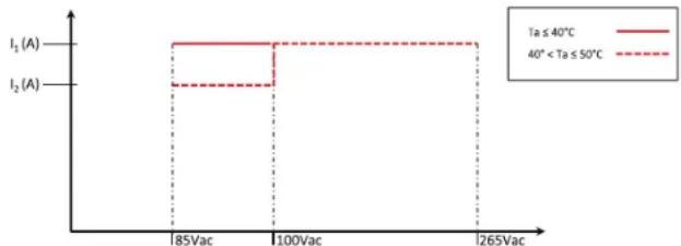
line
| Voltage | Current (A) | Temperature Range | |---|---|---| | 85Vac | I₂ (A) | Ta ≤ 40°C | | 100Vac | I₂ (A) | 40° < Ta ≤ 50°C | | 1265Vac | I₂ (A) | Ta ≤ 40°C | The chart displays a step function with two distinct voltage thresholds separated by a threshold at 100Vac. The current values are labeled as 'Ta ≤ 40°C' and '40° < Ta ≤ 50°C'.Fig. 2-1: Z*800 Rated Output Current Vs. Line Voltage and Ambient Temperature
2.5 Supplemental Characteristics
The supplemental characteristics give typical but non-warranted performance characteristics.
The supplemental characteristics are useful in assessing applications for the power supply. Several kinds of supplemental characteristics are listed below.
- Evaluation Data: Typical performance of the power supply.
- Reliability Data: Reliability performance of the power supply.
- IEC61000 Data: Performance of the power supply under IEC61000 test conditions.
- EMI Data: Typical EMI (conducted and radiated) performance of the power supply.
The supplemental characteristics data is held in each TDK-Lambda sales and service facility. For further details please contact the TDK-Lambda office near you.
2.6 Z200W/400W/600W/800W Outline Drawing
![BUS BAR PROTECTION CONNECTORS PROTECTION ANALOG CONTROL & MONITOR CONNECTOR IPL1-106-01-S-D-RA-K (SAMTEC) (SEE NOTE 5) [J1] SENSE PLUG IA710-81-06_ (J2) SIGNALS CONNECTOR IPL1-104-01-S-D-RA-K(SAMTEC) (SEE NOTE 6) [J3] RS232/RS485 COMMUNICATION CONNECTORS. (SEE NOTE 2) SEE NOTE 4. USB CONNECTOR TYPE B LAN CONNECTOR (OPTIONAL) LXI (LAN) LEDs IEC320-C16 AC INLET RUBBER LEGS 4 PLACES MARKED "B" (REMOVABLE) MOUNTING HOLES M4 3 PLACES MARKED "A" SEE NOTE 1. OUTPUT BUSBAR (+) 55.0 ±0.5 29.0 ±1.0 254.0 ±0.5 35.0 ±0.5 48.0 OUTPUT BUSBAR (-) 16.0 ±1.0 NOTE 1. MOUNTING SCREWS MUST NOT PROTRUDE INTO THE POWER SUPPLY MORE THAN 6.0 mm. 2. RS232/RS485 COMMUNICATION RJ-45. SHIE-DED, 8 CONTACTS CONNECTORS. 3. MODE, NAME AND OUTPUT RATING SHOWN HERE ACCORDING TO THE SPECIFICATION. 4. M6 OR 1/4" SCREWS FOR LOAD WIRES CONNECTION. 5. RECEPTACLE SAMTEC P/N IPD1-06-D-K CONTACT PIN SAMTEC CC79R-2024-01-L HAND TOOL: CAT-HT-179-2024-11 WIRE AWG 20-24. 6. RECEPTACLE SAMTEC P/N IPD1-04-D-K CONTACT PIN SAMTEC CC79R-2024-01-L HAND TOOL: CAT-HT-179-2024-11 WIRE AWG 20-24.](/content/2026/05/841135/images/cb090fcde3c703aeee7e506ff919231eb8f6cd58d2acbf795082a8ec13b4f405.jpg)
2.7 Z200W/400W/600W/800W Optional IEEE, Isolated Analog Interface Outline Drawing
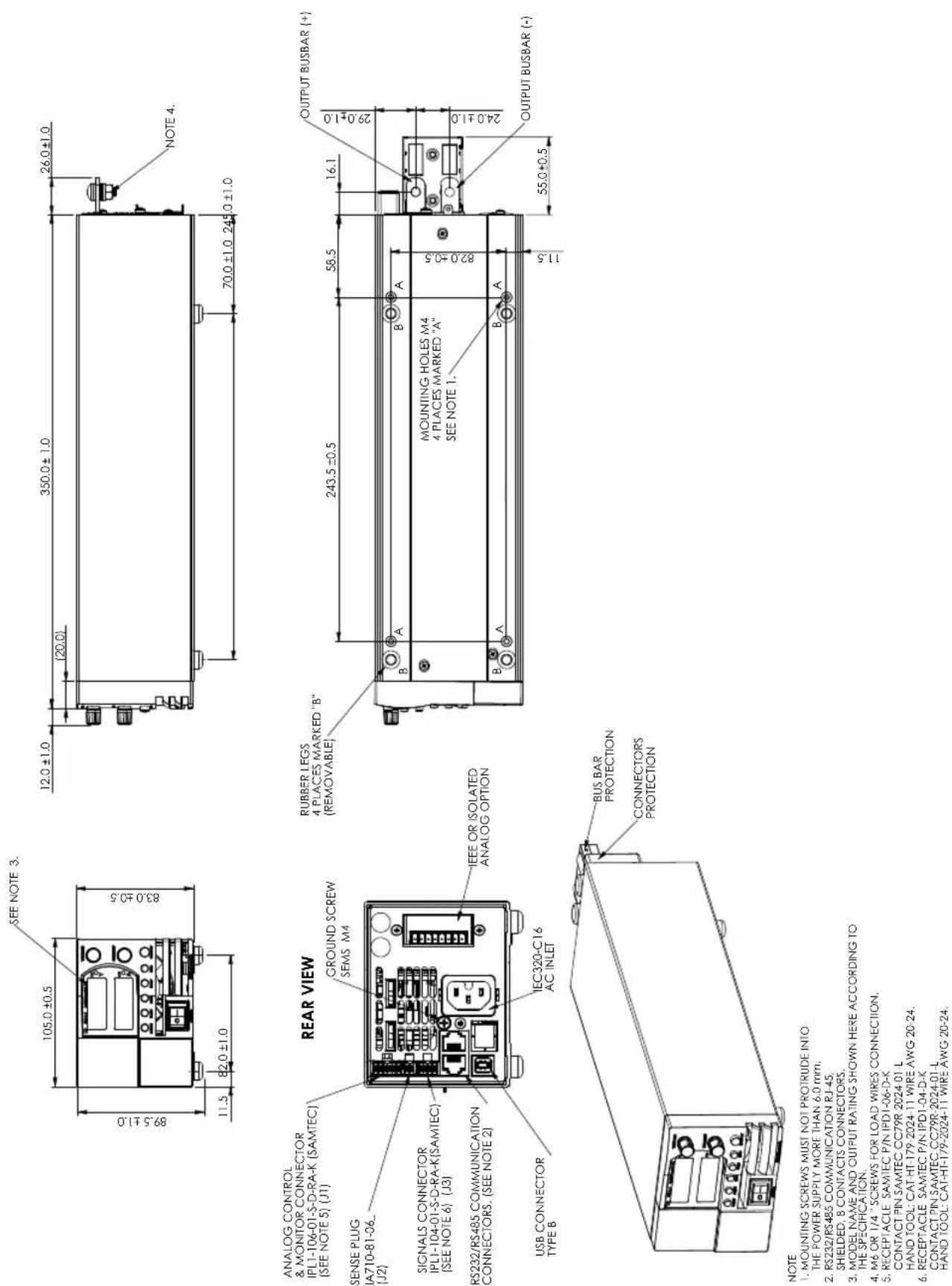
NOTE
1. MOUNTING SCREWS MUST NOT PROTRUDE INTO THE POWER SUPPLY MORE THAN 4.0 mm.
2. RS232/RS485 COMMUNICATION RJ-45.
SHIELDED, 8 CONTACTS CONNECTORS.
3. MODEL NAME AND OUTPUT RATING SHOWN HERE ACCORDING TO THE SPECIFICATION
4. M6 OR 1/4 " SCREWS FOR LOAD WIRES CONNECTION.
5. RECEPTACLE SAMTEC P/N IPD1-06-D-K
CONTACT PIN SAMIEC CC79R 2024 01 L
HAND TOOL: CAT.HT 178-2024.11 WIRE AWG 20.24
6. RECEPTACLE SAMTEC P/N IPD1-04-D-K
CONTACT PIN SAMTEC CC79R-2024-01-L
HAND TOOL: CAT-HT-179-2024-11 WIRE AWG 20-24.
2.8 Z200W/400W/600W/800W Front Panel Output Binding Post Outline Drawing
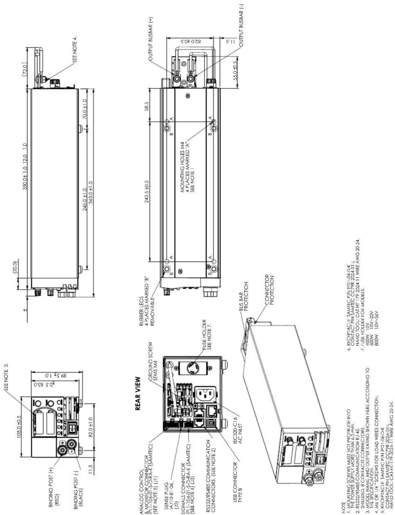
NOTE
- RECEPTACLE SAMTEC P/N IPD1-04-D-K CONTACT PIN SAMTEC CC79R 2024-01
HAND TOOL: CAT-HI 179-2024 IT WIRE AWG 20-24. 7. FUSE HOLDER FOR MODELS:
400W 10V 600W 10V\~20V 800W 10V\~36V
- MOUNTING SCREWS MUST NOT PROTRUDE INTO THE POWER SUPPLY MORE THAN 6.0 mm.
-
P5000175-195 COMMUNICATION D/45
-
RS232/RS485 COMMUNICATION RJ-45, SHIELDED, 8 CONTACTS CONNECTORS.
-
MODEL NAME AND OUTPUT RATING SHOWN HERE ACCORDING TO THE SPECIFICATION.
-
M6 OR 1/4" SCREWS FOR LOAD WIRES CONNECTION.
-
RECEPTACLE SAMTEC P/N IPD1-06-D-K CONTACT PIN SAMTEC GG78B 2024-01
CONTACT PIN SAMIEC CC79K-2024-01-L HAND TOOL: CAT-HI-179-2024-11 WIRE AWG 20-24.
CHAPTER 3: INSTALLATION
3.1 General
This chapter contains instructions for initial inspection, preparation for use and repackaging for shipment. Connection to PC, setting the communication port and linking Z^+ power supplies are described in Chapter 7.
NOTE:
Z^+ power supplies generate magnetic fields which might affect the operation of other instruments. If your equipment is susceptible to magnetic fields, do not position it adjacent to the power supply.
3.2 Preparation for Use
In order to be operational the power supply must be connected to an appropriate AC source. The AC source voltage should be within the power supply specification. Do not apply power before reading, Section 3.6 and 3.7.
Table 3-1 below, describes the basic setup procedure. Follow the instructions in Table 3-1 in the sequence given to prepare the power supply for use.
Step no. Item Description Reference
| 1 Inspection Initial physical inspection of the power supply Section 3.3 | ||
| 2 Installation | Installing the power supply, Ensuring adequate ventilation. | Section 3.4 Section 3.5 |
| 3 AC source | AC source requirements Connecting the power supply to the AC source. | Section 3.6 Section 3.7 |
4 Test Turn-on checkout procedure. Section 3.8
5 Load connection Wire size selection. Local /Remote sensing. Section 3.9
6 Default setting Single or multiple loads. Section 7.2.1
Table 3-1: Basic setup procedure
3.3 Initial Inspection
Prior to shipment this power supply was inspected and found free of mechanical or electrical defects. Upon unpacking of the power supply, inspect for any damage which may have occurred in transit. The inspection should confirm that there is no exterior damage to the power supply such as broken knobs or connectors and that the front panel and meter faces are not scratched or cracked. Keep all packing material until the inspection has been completed. If damage is detected, file a claim with carrier immediately and notify the TDK-Lambda sales or service facility nearest you.
3.4 Rack Mounting
The Z^+ power supply series is designed to fit in a standard 19" 2U height rack. Six units (70mm width) can be assembled into 19" 2U-rack. Refer to Fig.3-1. Four units (105mm width) can be assembled into 19" 2U-rack. Refer to Fig.3-2
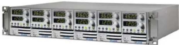
natural_image
Front view of a rack-mounted industrial control unit with multiple drive bays and indicator lights (no visible text or labels)Fig.3-1 Fig.3-2
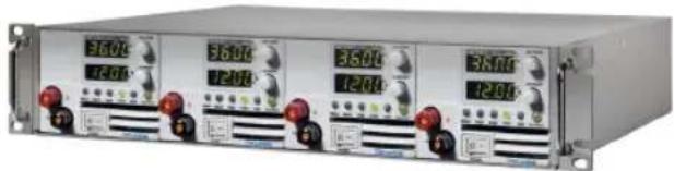
natural_image
Front view of a dual-chamber industrial control unit with multiple digital displays and red buttons (no visible text or labels)3.5 Location, Mounting and Cooling
This power supply is fan cooled. The air intake is at the front panel and the exhaust is at the rear panel. Upon installation allow cooling air to reach the front panel ventilation inlets. Allow minimum 10cm (4") of unrestricted air space at the front and the rear of the unit.
The power supply should be used in an area that the ambient temperature does not exceed +50°C.
3.6 AC Source Requirements
The Z^+ series can be operated from a nominal 100V to 240V, single phase, 47\~63Hz. The input voltage range and current required for each model is specified in Chapter 2. Ensure that under heavy load, the AC voltage supplied to the power supply does not fall below the specifications described in Chapter 2.
Some components inside the power supply are at AC voltage even when the On/Off switch is in the "Off" position. To avoid electric shock hazard, disconnect the line cord and load and wait two minutes before removing cover.
WARNUNG:
An IEC connector is provided on the rear panel for connecting the unit to the AC power source with an AC cord. The IEC connector also provides the safety ground connection while the AC cord is plugged into an appropriate AC.
3.7.2 AC Input Cord
Refer to section 1.3.4 for details of the AC input cords recommended.
WARNING:
The AC input cord plug is the disconnect device of the power supply. The plug must be readily identifiable and accessible to the user. The AC input cord must be no longer than 3m.
WARNUNG:
The following procedure ensures that the power supply is operational and may be used as a basic incoming inspection check.
3.8.2 Prior to Operation
- Ensure that the power supply is configured to the default setting:
AC On/Off switch at Off position.
Sense connector : Configured to Local Sense as shown in Fig.3-3:
1 Local (-) sense
2 (-) Sense
3 (+) Sense
4 Local (+) sense
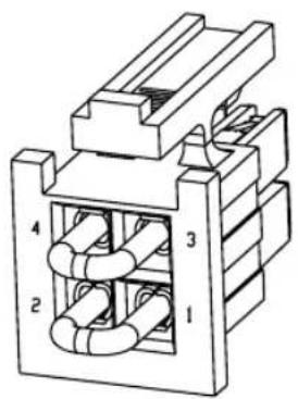
natural_image
Technical line drawing of a mechanical or electrical component with numbered parts (1, 2, 3, 4) and no visible text or symbols.Plug P/N: IPD1-02-D-K (SAMTEC)
Fig.3-3: Sense connector default connection
- Ensure that the protection of output bus-bars or of output connector is mounted and properly assembled for power supplies when the output voltage exceed 42.4VDC.
- Connect the unit to an AC source as described in section 3.7.
- Connect a DVM with appropriate cables for the rated voltage to the output terminals.
- Turn the front panel AC power switch to On.
- When power supply is turned ON the display shows "8888" and all LEDs illuminate momentarily. The power supply operating status is then displayed.
3.8.3 Constant Voltage Check
- Turn on the output by pressing OUTPUT button so the OUTPUT LED illuminates.
- Observe the power supply Voltage display and rotate the Voltage encoder.
Ensure that the output voltage varies while the Voltage encoder is rotated.
The minimum control range is from zero to the maximum rated output for the power supply model. Compare the DVM reading with the front panel Voltage display to verify the accuracy of the Voltage display. Ensure that the front panel CV LED illuminates.
- Turn off the front panel AC power switch.
3.8.4 Constant Current Check
Ensure that the front panel AC power switch is at Off position and the DVM connected to the output terminals shows zero voltage.
- Connect DC shunt across the output terminals. Ensure that the shunt and the wires current ratings are higher than the power supply rating. Connect a DVM to the shunt.
- Turn the front panel AC power switch to On position.
- Turn on the output by pressing OUTPUT button so the OUTPUT LED illuminates.
- Observe the power supply Current display and rotate the Current encoder. Ensure that the output current varies while the Current encoder is rotated. The minimum control range is from zero to the maximum rated output for the power supply model. Compare the DVM reading with the front panel Current display to verify the accuracy of the Current display. Ensure that the front panel CC LED is on.
- Turn off the front panel AC power switch.
- Remove the shunt from the power supply output terminals.
3.8.5 OVP Check
Refer to Section 5.3.2 for explanation of the OVP function prior to performing the procedure below.
- Turn the front panel AC power switch to On position and turn on the output by pressing OUTPUT button.
- Using the Voltage encoder, adjust the output voltage to approx. 10% of the unit voltage rating.
- Set OVP to 50% of of the unit voltage rating.
- Adjust the output voltage toward it's maximum and check that the output voltage cannot be increased more than the OVP setting.
- Adjust OVP limit to the maximum.
3.8.6 UVL Check
The UVL can be set when the power supply output is Enabled (On) or Disabled (Off). UVL setting values are limited at the maximum level to approximately 5% below the Output Voltage setting. Attempting to adjust the value above this limit will result in no response to the adjustment attempt. The minimum value setting is zero.
- Press PROT button, PROT (GREEN) LED illuminates. Current display shows "UUP" message.
- Press Current Encoder. Voltage Display shows "UUL" message, Current display shows setting level.
- Rotate the Voltage encoder to set "UUL".
- Rotate the Current encoder to adjust the level.
- Press PROT button twice or wait 15 sec. to return display to its previous state and then PROT LED turns OFF.
- Adjust the output voltage toward it's minimum and check that the output voltage cannot be decreased below the UVL setting.
- Adjust the UVL limit to the minimum.
3.8.7 Foldback Check
WARNING:
There is a potential shock hazard when checking a power supply with output voltage greater than 42.4V. Observe proper safety procedures during the checking.
WARNUNG:
Refer to Section 5.3.4 for explanation of the FOLD function prior to performing the procedure below.
- Ensure that the output voltage is set to approx. 10% of the unit rating.
- Adjust the Current encoder to set the current limit to approx. 10% of the unit rating.
- Set Foldback to CC MODE.
- Short the output terminals momentarily (approx. 0.5 sec.). Ensure that the output voltage falls to zero, the Voltage display shows "FOLd", Current display shows "FAIL" and the PROT red LED blinks.
- Set Foldback to OFF. The output voltage remains zero.
- Press OUTPUT button. Ensure that the output voltage returns to it's last setting.
- Turn the output off by pressing OUTPUT button. Ensure that the Voltage display shows "OFF".
3.9 Connecting the Load
Turn off the AC input power before making or changing any rear panel connection. Ensure that all connections are securely tightened before applying power. There is a potential shock hazard when using a power supply with a rated output greater than 42.4V.
WARNING:
There is a potential shock hazard when using a power supply with a rated output voltage greater than 42.4V. Turn off the AC input power before making or changing any rear panel connection.
Ensure that the protection of output bus-bars or of output connector is mounted and properly assembled for power supplies when output voltage exceed 42.4VDC. Ensure that all connections are securely tightened before applying power.
WARNUNG:
The following considerations should be made to select wiring for connecting the load to the power supply:
• Current carrying capacity of the wire (refer to 3.9.2)
- Insulation rating of the wire should be at least equivalent to the maximum output voltage of the power supply.
• Maximum wire length and voltage drop (refer to 3.9.2)
- Noise and impedance effects of the load wiring (refer to 3.9.4).
3.9.2 Current Carrying Capacity
Two factors must be considered when selecting the wire size:
-
Wires should be at least heavy enough not to overheat while carrying the power supply load current at the rated load, or the current that would flow in the event the load wires were shorted, whichever is greater.
-
Wire size should be selected to enable voltage drop per lead to be less than 1.0V at the rated current. Although units will compensate higher voltage drop in each load wire (refer to the specifications). It is recommended to minimize the voltage drop (1V maximum) to prevent excessive output power consumption from the power supply and poor dynamic response to load changes. Please refer to Tables 3-2 and 3-3 for maximum wire length to limit voltage drop in American and European dimensions respectively.
| Wire size AWG | Resistivity Ohm/1000ft | Maximum length in feet to limit voltage drop to 1V or less |
| 5A 10A 20A 50A 80A | ||
| 14 2.526 80 40 20 8 5 | ||
| 12 1.589 120 60 30 12 7.5 | ||
| 10 0.9994 200 100 50 20 12.5 | ||
| 8 0.6285 320 160 80 32 20 | ||
| 6 0.3953 500 250 125 50 31 | ||
| 4 0.2486 800 400 200 80 50 | ||
| 2 0.1564 1200 600 300 125 78 | ||
Table 3-2: Maximum wire length for 1V drop on lead (in feet)
| Cross sect. area (mm2) | Resistivity Ohm/Km | Maximum length in meters to limit voltage drop to 1V or less |
| 5A 10A 20A 50A 80A | ||
| 2.5 8.21 24.0 12 6 | 2.4 | 1.5 |
| 4 5.09 39.2 18.6 9.8 | 4 2.5 | |
| 6 3.39 59.0 29.4 14.8 5.8 | 3.6 | |
| 10 1.95 102.6 | 51.2 25.6 10.2 6.3 | |
| 16 1.24 160.0 | 80 40 16 10 | |
| 25 0.795 250.0 | 125 62 25.2 15.7 | |
| 35 0.565 354.0 | 177 88 35.4 22 |
Table 3-3: Maximum wire length for 1V drop on lead (in meters)
For currents not shown in Table 3-2 and 3-3, use the formula:
Maximum length=1000/(current x resistivity)
Where current is expressed in amperes and resistivity in ohms/km or ohms/1000ft.
3.9.3 Wire Termination
The wires should be properly terminated with terminals securely attached. DO NOT use non-terminated wires for load connection at the power supply.
CAUTION:
When local sensing, a short from +LS or +S to -V or -S or -LS, will cause damage to the power supply. Reversing the sense wires might cause damage to the power supply in local and remote sensing. (Do not connect -S to +V or +S to -V.)
3.9.4 Noise and Impedance Effects
To minimize the noise pickup or radiation, the load wires and remote sense wires should be twisted pairs to the shortest possible length. Shielding of sense leads may be necessary in high noise environments. Where shielding is used, connect the shield to the chassis via a rear panel Ground screw. Even if noise is not a concern, the load and remote sense wires should be twisted-pairs to reduce coupling, which might impact the stability of power supply. The sense leads should be separated from the power leads.
Twisting the load wires reduces the parasitic inductance of the cable which could produce high frequency voltage spikes at the load and the output of power supply, because of current variation in the load itself.
The impedance introduced between the power supply output and the load could make the ripple and noise at the load worse than the noise at the power supply rear panel output. Additional filtering with bypass capacitors at the load terminals may be required to bypass the high frequency load current.
3.9.5 Inductive Loads
Inductive loads can produce voltage spikes that may be harmful to the power supply. A diode should be connected across the output. The diode voltage and current rating should be greater than the power supply maximum output voltage and current rating. Connect the cathode to the positive output and the anode to the negative output of the power supply.
Where positive load transients such as back EMF from a motor may occur, connect a surge suppressor across the output to protect the power supply. The breakdown voltage rating of the suppressor must be approximately 10% higher than the maximum output voltage of the power supply.
3.9.6 Making the Load Connections
WARNING:
There is a potential shock hazard when using a power supply with an output voltage greater than 42.4V. To protect personnel against accidental contact with hazardous voltages, ensure that the protection of output bus-bars or of output connector is mounted and properly assembled. Ensure that the load and its connections have no accessible live parts. Ensure that the load wiring insulation rating is greater than or equal to the maximum output voltage of the power supply.
WARNUNG:
Ensure that the load wiring mounting hardware does not short the output terminals. Heavy connecting cables must have some form of strain relief to prevent loosening the connections or bending the bus-bars.
10V to 100V Models
Refer to Fig.3-4 for connection of the load wires to the power supply bus-bars and to Fig.3-5 for mounting the bus-bars shield to the chassis.
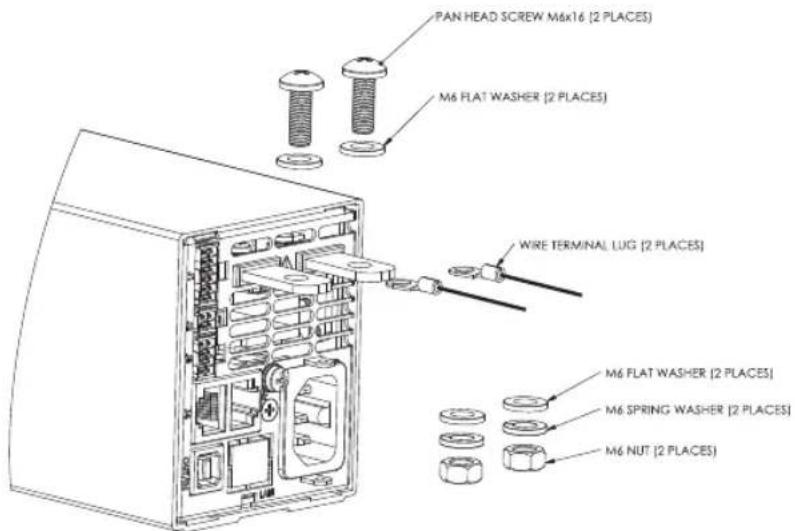
Fig. 3-4: Load wires connection, 10V to 100V models.
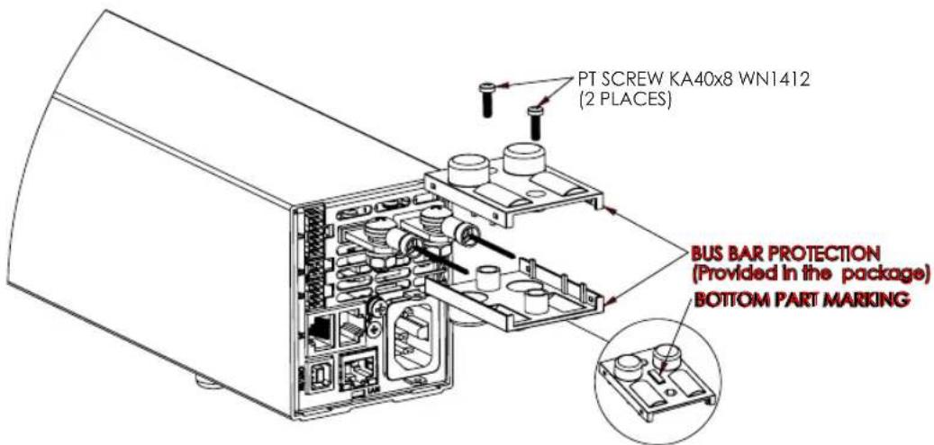
Fig. 3-5: Bus-bars shield mounting
100V Models
WARNING:
There is a potential shock hazard when using a power supply with an output voltage greater than 42.4V. Do not turn ON power supply an output voltage above 42.4VDC without output bus-bars or output connector protection assembled.
Ensure that the protection of output bus-bars or of output connector is mounted and properly assembled, and that the bus bar protection is locked by a two SEMS type screws as described in Fig. 3.5
WARNUNG:
Fig.3-6 shows recommended load and sensing connections for a single load. The local sense lines shown are default connections at the rear panel J2 sense connector. Local sensing is suitable for applications where load regulation is less critical.
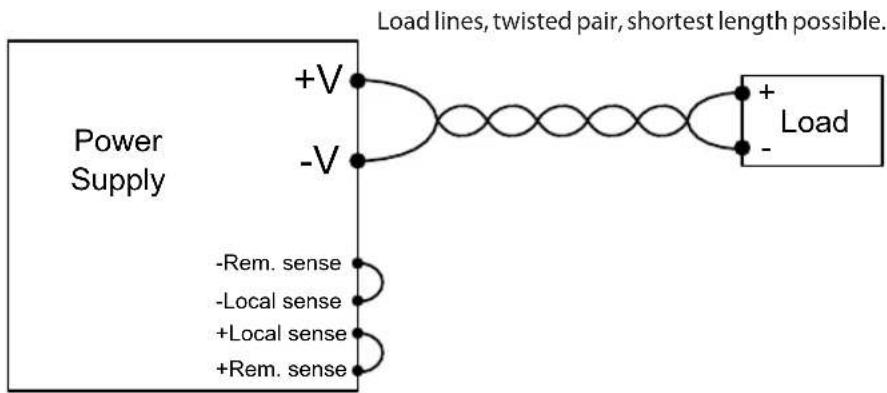
Fig.3-6: Single load connection, local sensing
3.9.8 Connecting Single Loads, Remote Sensing
Fig.3-7 shows recommended remote sensing connection for single loads. Remote sensing is used when, in Constant Voltage mode, the load regulation is important at the load terminals. Use twisted or shielded wires to minimize noise pick-up. If shielded wires are used, the shield should be connected to the ground at one point, either at the power supply chassis or the load ground. The optimal point for the shield ground should be determined by experimentation.
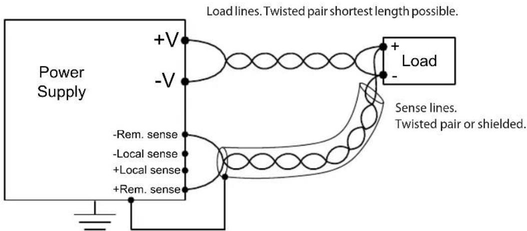
Fig.3-7: Remote sensing, single load
3.9.9 Connecting Multiple Loads, Radial Distribution Method
Fig.3-8 shows multiple loads connected to one supply. Each load should be connected to the power supply's output terminals using separate pairs of wires. It is recommended that each pair of wires will be as short as possible and twisted or shielded to minimize noise pick-up and radiation. The sense wires should be connected to the power supply output terminals or to the load with the most critical load regulation requirement.
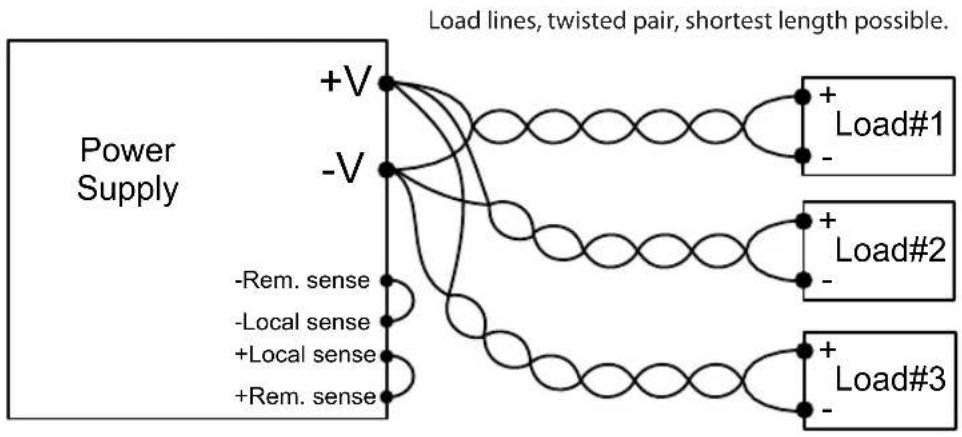
flowchart
graph TD
    A["Power Supply"] --> B["+V"]
    A --> C["-V"]
    B --> D["Load#1"]
    C --> E["Load#2"]
    C --> F["Load#3"]
    B --> G["-Rem. sense"]
    C --> H["-Local sense"]
    C --> I["+Local sense"]
    C --> J["+Rem. sense"]
    D --> K["+"]
    E --> L["+"]
    F --> M["+"]
    style A fill:#f9f,stroke:#333
    style B fill:#ccf,stroke:#333
    style C fill:#ccf,stroke:#333
    style D fill:#cfc,stroke:#333
    style E fill:#cfc,stroke:#333
    style F fill:#cfc,stroke:#333
    style G fill:#ffc,stroke:#333
    style H fill:#ffc,stroke:#333
    style I fill:#ffc,stroke:#333
    style J fill:#ffc,stroke:#333
Fig.3-8: Multiple loads connection, radial distribution, local sense
3.9.10 Multiple Load Connection with Distribution Terminals
If remotely located output distribution terminals are used, the power supply output terminals should be connected to the distribution terminals by a pair of twisted and/or shielded wires. Each load should be separately connected to the remote distribution terminals (see Fig.3-9). If remote sensing is required, the sensing wires should be connected to the distribution terminals or at the most critical load.
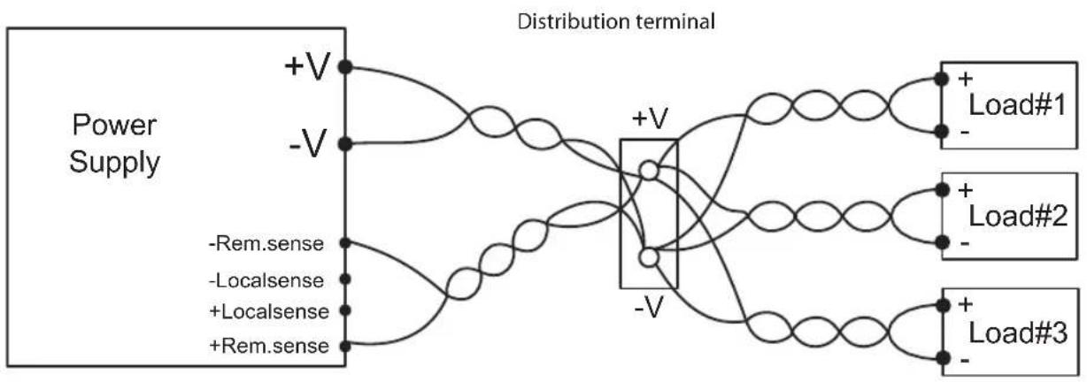
flowchart
graph LR
    A["Power Supply"] --> B["+V"]
    A --> C["-V"]
    A --> D["-Rem.sense"]
    A --> E["-Localsense"]
    A --> F["+Localsense"]
    A --> G["+Rem.sense"]
    B --> H["Distribution terminal"]
    C --> H
    D --> H
    E --> H
    F --> H
    G --> H
    H --> I["+ Load#1"]
    H --> J["+ Load#2"]
    H --> K["+ Load#3"]
Fig.3-9: Multiple loads connection with distribution terminal
3.9.11 Grounding Outputs
Either the positive or negative output terminals can be grounded. To avoid noise problems caused by common-mode current flowing from the load to ground, it is recommended to ground the output terminal as close as possible to the power supply chassis ground.
Always use two wires to connect the load to the power supply regardless of how the system is grounded.
WARNING:
Models up to 100VDC Rated Output shall not float outputs more than +/-100VDC above/below chassis ground.
WARNUNG:
3.10 Local and Remote Sensing
The rear panel J2 sense connector is used to configure the power supply for local or remote sensing of the output voltage. Refer to Fig.3-10 for sense connector location.
3.10.1 Sense Wiring
WARNING:
There is a potential shock hazard at the sense connector when using a power supply with an output voltage greater than 42.4V. Local sense and remote sense wires should have a minimum insulation rating equivalent or greater than the maximum output voltage of the power supply. Ensure that the connections at the load end are shielded to prevent accidental contact with hazardous voltages.
WARNUNG:
The power supply is shipped with the rear panel J2 sense connector wired for local sensing of the output voltage. Refer to Table 3-4 for J2 terminals assignment. With local sensing, the output voltage regulation is made at the output terminals. This method does not compensate for voltage drop on the load wires, therefore it is recommended only for low load current applications or where the load regulation is less critical.
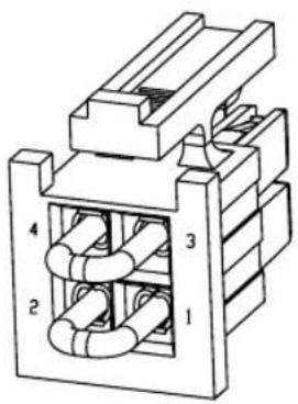
Fig.3-10: Sense connector location
Terminal Function
J2-1 Local negative sense. Connected internally to the negative output terminal (-LS).
J2-2 Remote negative sense (-S).
J2-3 Remote positive sense (+S).
J2-4 Local positive sense. Connected internally to the positive output terminal (+LS).
Table 3-4: J2 terminals
3.10.3 Remote Sensing
WARNING:
There is a potential shock hazard at the sense point when using power supply with an output voltage greater than 42.4V. Ensure that the connections at the load end are shielded to prevent accidental contact with hazardous voltages.
WARNUNG:
Do not operate the Power Supply with remote sense wire connected to the load without connecting load wire to the output terminal. Make sure that the connection is reliable to avoid disconnection during operation. Disconception may cause damage to the power supply.
CAUTION:
When using shielded sense wires, ground the shield in one place only. The location can be the power supply chassis or one of the output terminals.
Use remote sense where the load regulation at the load end is critical. In remote sense, the power supply will compensate for voltage drop on the load wires. Refer to the specifications for the maximum voltage drop on load wires. The voltage drop is subtracted from the total voltage available at the output. Follow the instructions below to configure the power supply for remote sensing:
- Ensure that the AC On/Off is in the Off position.
- Remove the local sense jumpers from J2.
- Connect the negative sense lead to terminal J2-2 (-S) and the positive sense lead to terminal J2-3(+S) of the J2 mating connector. Ensure that the J2 mating connector is plugged securely into the rear panel sense connector, J2.
- Turn On the power supply.
NOTES:
-
If the power supply is operating in remote sense and either the positive or negative load wire is not connected, an internal protection circuit will activate and shut down the power supply. To resume operation, turn the AC On/Off to the Off position, connect the open load wire, and turn On the power supply.
-
If the power supply is operated without the remote sense lines or local sense jumpers, it will continue to work, but the output voltage regulation will be degraded. Also, the OVP circuit may activate and shut down the power supply.
3.10.4 J2 Sense Connector Technical Information
- J2 connector type: IPL1-102-01-S-D-RA-K, SAMTEC.
- Plug type: IPD1-02-D-K, SAMTEC.
- Contact pins: CC79R-2024-01-L, SAMTEC.
- Wire AWG: 24 up to 20
3.11 Repackaging for Shipment
To ensure safe transportation of the instrument, contact the TDK-Lambda sales or service facility near you for Return Authorization and shipping information. Please attach a tag to the power supply describing the problem and specifying the owner, model number and serial number of the power supply. Refer to Warranty Information for further instructions.
CHAPTER 4: FRONT/REAR PANEL CONTROLS AND CONNECTORS
4.1 Introduction
The Z^+ Power Supply series has a full set of controls, indicators and connectors that allow the user to set up and operate the unit. Before starting to operate the unit, please read the following sections for an explanation of the functions, controls and connector terminals.
- Section 4.2: Front Panel Display and Controls.
- Section 4.3: Rear Panel Controls and Connectors.
4.2 Front Panel Display and Controls
Refer to Fig4-1 and Table 4-1 for description of the Front Panel controls and indicators.
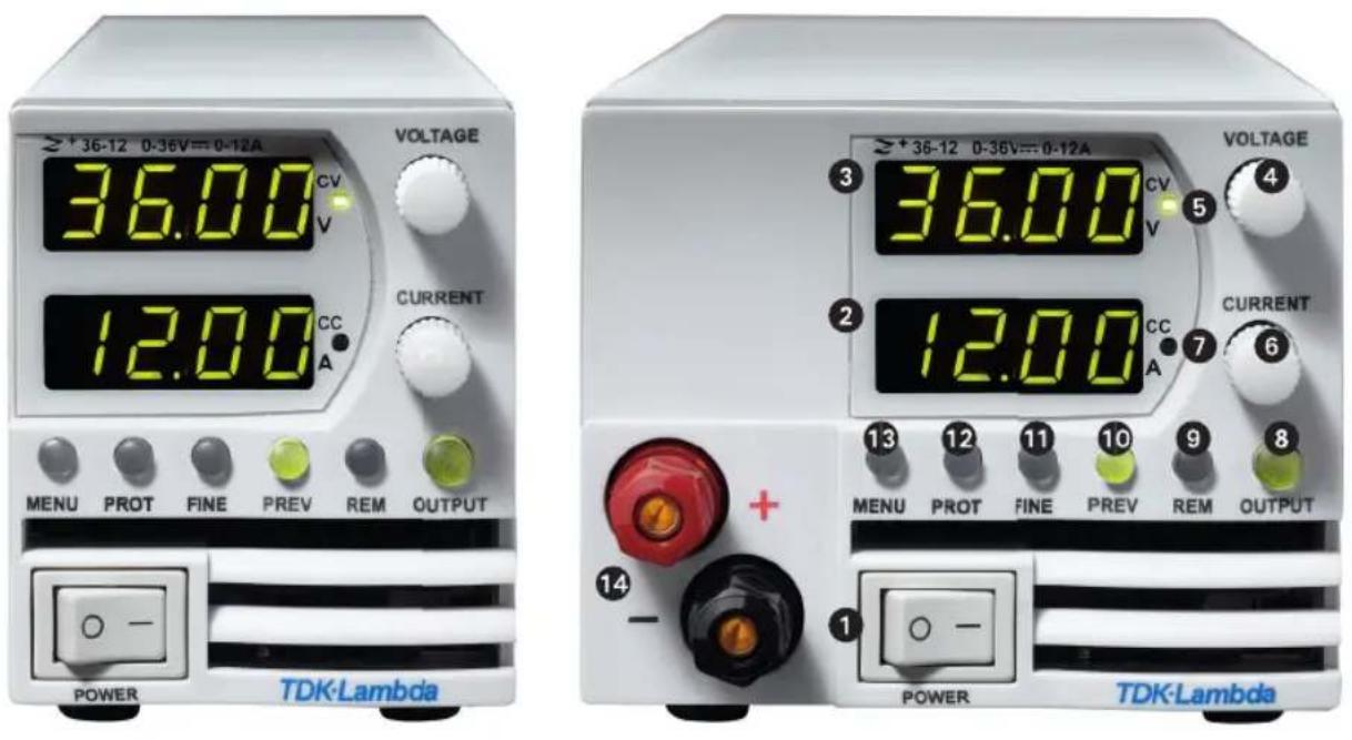
Fig. 4-1: Front panel controls and indicators
| No. | Control/Indicator Description | Section | |
| 1 AC | Power Switch AC ON/OFF control | ||
| 2 Current display | 4 digit 7-segment LED display. Normally displays the output current.In preview mode, the display indicates the program setting of output current. | ||
| 3 Voltage Display | 4 digit 7-segment LED display. Normally displays the output voltage.In preview mode, the display indicates the program setting of output voltage. | ||
| 4 | Voltage encoder and button | Encoder : high resolution rotary Encoder for adjusting the output voltage. Button: Auxiliary function to select between menu levels. | 5.2.1 |
| 5 | Constant Voltage mode indicator | Green LED, light for Constant-Voltage mode operation. | |
| 6 | Current encoder and button | Encoder: High resolution rotary Encoder for adjusting the output current.Button: Auxiliary function to select between menu levels. | 5.2.2 |
| 7 | Constant Current mode indicator | Green LED, light for Constant-Current mode operation. | |
| 8 | OUTPUT button/indicator | Main function: output ON/OFF control. Press OUTPUT to set the output ON or OFF. Press to recovery after OVP, UVP or FOLD fails. Green LED, lights when the DC Output is enabled.Auxiliary function: Select between Safe Start and Auto Start modes. | 5.2.45.2.5 |
| 9 REM | button/indicator | Main function: Go to local. Press REM to put the unit into local (REM button is disabled at Local Lockout mode. Green LED, lights when the unit is in communication Remote mode.Auxiliary function: Communication menu. | |
| 10 PREV button/indicator | Main function: Press PREV to display the output voltage and current limit setting. For 5 sec. the display will show the setting and then it will return to show the actual output voltage and current. Green LED, lights when PREV button is pressed.Auxiliary function: Front Panel Lock. Press and hold PREV button to toggle between "Locked front panel" and "Unlocked front panel". The display will cycle between LFP and UFP. Releasing the PREV button while one of the modes is displayed, selects that mode. | ||
| 11 FINE button/indicator | Voltage, Current, Delay and Counter Fine/Coarse adjustment control. Operates as a toggle switch. In Fine mode, the VOLTAGE and Current encoders operate with high resolution and in Coarse mode with lower resolution (approx. 6 turns). Green LED, lights when the unit is in Fine mode. | ||
| 12 | PROT button/Alarm indicator | Main function: Red LED blinks in cases of fault detection: OVP, UVP, OTP, Foldback, Interlock and AC fail. Auxiliary function: Protection menu.Green LED illuminates when the unit is in protection menu mode. | 5.3 |
| 13 | Main Menu button/indicator | Used for selection between analog or digital mode control, rear panel control parameters, memory management, trigger and program setting, parallel mode settings and software version. | |
| 14 Optional Output Jack Output | Jacks for modules up to 60V: 24A Max | ||
Table 4-1: Front panel controls and indicators
4.3 Rear Panel Connectors
Refer to Fig.4-2 and Table 4-2 for description of the Rear Panel connectors.
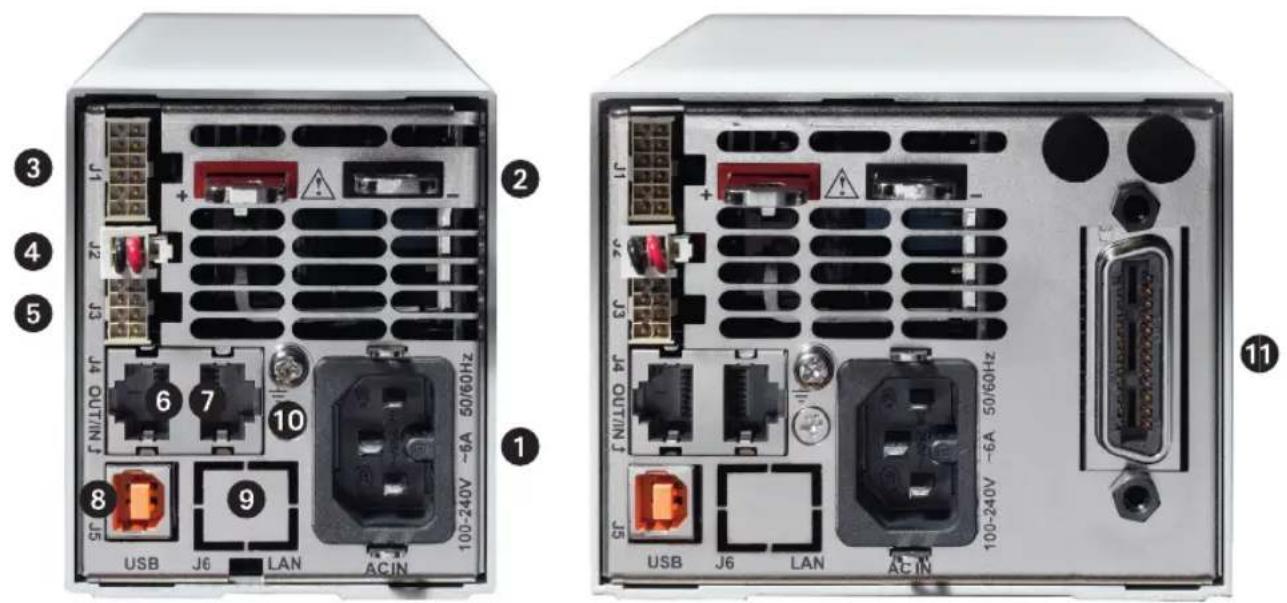
Fig. 4-2: Rear panel connections
| No. | Connection Description Section | ||
| 1 AC | Input Connector IEC320-16 | TYPE CONNECTOR | |
| 2 DC | output bus-bar Bus-bars for | 10V to 100V models. Use M6 or 1/4" screws. 3.9 | |
| 3 | Analog Control and signals. J1 | Connector for remote analog interface. Analog control and monitoring. Referenced internally to output potential -S. | 4.3.1 |
| 4 | Local/Remote sense connector J2 | Connector for making remote sensing connections to the load for regulation of the load voltage and compensation of load wire drop. | 3.10 |
| 5 | Isolated control and signal. J3 | Control and monitoring signal, isolated from the output potential. 4.3.2 | |
| 6 | Remote Serial Out connector | RJ-45 type connector, used for chaining power supplies to/from a serial communication bus. | 7.3 |
| 7 | Remote Serial In connector | RJ-45 type connector, use for connecting power supplies to RS232 or RS485 port of computer for remote control purposes. When using several power supplies in a power system, the first unit Remote-In is connected to the computer and the remaining units are chained, Remote-In to Remote-Out. | 7.3 |
| 8 USB | Connector USB interface connector, type B | ||
| 9 | LAN Connector (optional) | LAN interface connector, type RJ-45 | |
| 10 | Ground screw M4X8 for chassis | Ground connection | |
| 11 | Optional Interface Position for | GPIB Interface (shown) or Isolated Analog Interface. |
Table 4-2: Rear panels connections
WARNING:
Terminals 7, 9 and 12 of J1 are connected internally to the negative sense(-S) potential of the power supply. Do not attempt to bias any of these terminals relative to the negative sense. Use the Isolated Programming interface option to allow control from a programming source at a different potential relative to the power supply negative.
CAUTION:
To prevent ground loops and to maintain the isolation of the power supply when programming from J1, use an ungrounded programming source.
WARNING:
There is a potential shock hazard at the output when using a power supply with output greater than 42.4V. Use wires with minimum insulation rating equivalent to the maximum output voltage of the power supply.
WARNUNG:
Control and monitoring signals are referenced to the negative sense potential (-S).
Connector Technical Information:
• Connector type: IPL1-106-01-S-D-RA-K, SAMTEC
• Receptacle type: IPD1-06-D-K, SAMTEC
- Contact pins: CC79R-2024-01-L, SAMTEC
• Hand tool: CAT-HT-179-2024-11, SAMTEC
• Wire: AWG 20-24
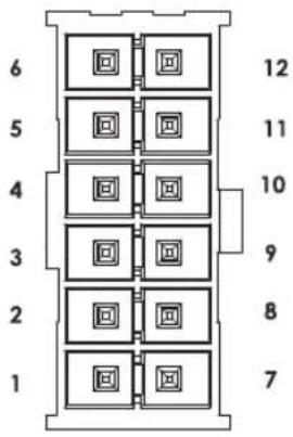
Fig.4-3: J1 connector terminals and functions
| Pin Parameter Specification Section | |||
| 1 LOC/REM SELECT | Input for selecting between Local or Remote analog programming of output voltage and output current. | 6.2 | |
| 2 P Output for current balance in parallel operation 5.5 | |||
| 3 I_MON | Monitoring power supply | output current 6.6 | |
| 4 LOC/REM MON | Output for indicating if the unit is in Local or Remote analog programming mode. | ||
| 5 IPGM | Input for remote analog voltage/resistance programming of the Output Current. | 6.4, 6.5 | |
| 6 VPGM | Input for remote analog voltage/resistance programming of the Output Voltage. | 6.4, 6.5 | |
| 7 COM | Control Common. Return for VMON, IMON, CV/CC, LOC/REM. Connected internally to the negative sense potential (-S). | ||
| 8 CV/CC | Output for Constant-Voltage / Constant-Current mode indication. | 5.8.1 | |
| 9 COM | Control Common. Return for VMON, IMON, CV/CC, LOC/REM. Connected internally to the negative sense potential (-S). | ||
| 10 V_MON | Output for monitoring the power supply Output Voltage. 6.6 | ||
| 11 IPGM | RTN Return for IPGM input. | ||
| 12 | VPGM_RTN | Return for VPGM input. Connected internally to the "-S". | |
Table 4-3: J1 connector terminals and functions
4.3.2 J3 Connector Terminal and Function
Control and monitoring signals are isolated from the power supply output.
Connector Technical Information
- Connector type: IPL1-104-01-S-D-RA-K, SAMTEC
• Receptacle type: IPD1-04-D-K, SAMTEC - Contact pins: CC79R-2024-01-L, SAMTEC
• Hand tool: CAT-HT-179-2024-11, SAMTEC - Wire: AWG 20-24
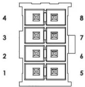
Fig.4-4: J3 connector terminals and functions
| Pin Signal name Function Section | |||
| 1 Programmed Signal 1 General Purpose Open collector Port 1 5.7.3 | |||
| 2 PS_OK Output for indication of the power supply status. High level is OK. 5.7.4 | |||
| 3 Trigger Out Trigger output, positive true, pulse width: Min. 10usec 8.5.2 | |||
| 4 | ILC | Enable /Disable the power supply output by dry-contact (short/open). | 5.7.2 |
| 5 | Shut Off (SO) | Input for shut off control of the power supply output. | 5.7.1 |
| 6 Programmed Signal 2 General Purpose Open collector Port 2 5.7.3 | |||
| 7 IFC_COM Isolated interface, common. | |||
| 8 Trigger In CMOS level input for triggering power supply output. Positive edge,pulse width: Min. 10usec. | 8.5.1 | ||
Table 4-4: J3 connector terminals and functions
4.4 Front Panel Display Messages
Table 4-5 shows the various messages that will be shown on the display in different operating modes.
| Display Text | Text Description |
| Abor | ABORT |
| AC | AC |
| Adr | ADDRESS |
| Auto | AUTO (RESTART) |
| BAud | BAUD RATE |
| BUS | BUS |
| Cont | CONTINUE |
| COUN | COUNTER |
| Curr | CURRENT |
| CC | CC |
| CU | CV |
| d IS | DISABLE |
| EnR | ENABLE |
| E.r ES | EXT.RESISTOR |
| Err | ERROR |
| E.UOL | EXT.VOLTAGE |
| EHt | EXTERNAL |
| F.rSt | FACTORY RESET |
| FA IL | FAIL |
| FOLD | FOLDBACK |
| F.PAN | FRONT PANEL |
| F.Str | FUNCTION STROBE |
| GEN | GEN LANGUAGE |
| HOLD | HOLD |
| HOST | HOST |
| Info | INFORMATION |
| in it | INITIALIZE |
| INF | INTERFACE |
| ILC | INTERLOCK |
| IP | IP |
| LAN | LAN |
| LANG | LANGUAGE |
| LOAD | LOAD |
| NEG | NEGATIVE |
| MAC | MAC |
| NETO | MEMORY |
| OFF | OFF |
| Display Text | Text Description |
| ON | ON |
| ONCE | ONCE |
| OTP | OTP |
| OUP | OVP |
| PrLL | PARALLEL |
| P_in1 | PIN 1 |
| P_in2 | PIN 2 |
| POS | POSITIVE |
| PrOG | PROGRAM |
| Pr.dL | PROTECTION DELAY |
| PSd | PS_OK DELAY |
| rANG | RANGE |
| r_PAN | REAL PANEL |
| rECL | RECALL |
| rSt | RESET |
| rEu. | REVISION |
| 232 | RS232 |
| 485 | RS485 |
| SAFE | SAFE (START) |
| SAVE | SAVE |
| SCPI | SCPI |
| SO | SHUT OFF |
| SET | SET |
| SLUE | SLAVE |
| SLAd | SLAVE (ADVANCED) |
| SL | SLAVE (BASIC) |
| STEP | STEP |
| tr_IG | TRIGGER |
| tr_dL | TRIGGER DELAY |
| tr_In | TRIGGER IN |
| tr_Ou | TRIGGER OUT |
| USB | USB |
| UUL | UVL |
| UVP | UVP |
| UOLT | VOLTAGE |
| YES | YES |
Table 4-5: Front Panel display messages
4.5 Navigating the Main Menu
4.5.1 Introduction
The Main Menu consists of three levels: Subsystem, Function and Parameter. To enter the Menu press the Menu button. The Menu LED illuminates and the display shows the Subsystem Menu. Navigate by rotating the Voltage encoder to scroll through the Subsystem list (first level). Repeat these actions to navigate the Functions list (second level). In the third level, the Voltage display shows the function and the Current display shows the parameter. Scroll the parameter list by rotating the Current encoder and press to select the desired parameter. When parameter is accepted, the display blinks once and exits to the previous level.
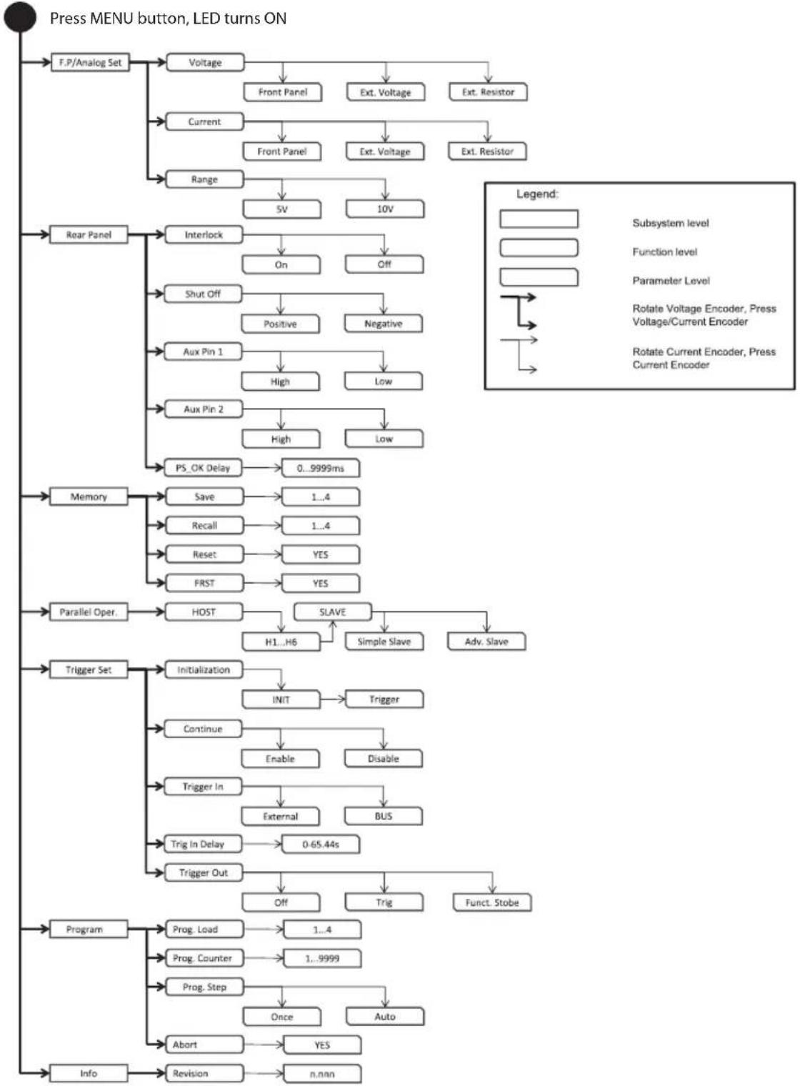
flowchart
graph TD
    A["Press MENU button, LED turns ON"] --> B["F.P/Analog Set"]
    B --> C["Voltage"]
    C --> D["Front Panel"]
    C --> E["Ext. Voltage"]
    C --> F["Ext. Resistor"]
    B --> G["Current"]
    G --> H["Front Panel"]
    G --> I["Ext. Voltage"]
    G --> J["Ext. Resistor"]
    B --> K["Range"]
    K --> L["5V"]
    K --> M["10V"]
    B --> N["Rear Panel"]
    N --> O["Interlock"]
    O --> P["On"]
    O --> Q["Off"]
    N --> R["Shut Off"]
    R --> S["Positive"]
    R --> T["Negative"]
    N --> U["Aux Pin 1"]
    U --> V["High"]
    U --> W["Low"]
    N --> X["Aux Pin 2"]
    X --> Y["High"]
    X --> Z["Low"]
    N --> AA["PS_OK Delay"]
    AA --> AB["0...9999ms"]
    B --> AC["Memory"]
    AC --> AD["Save"]
    AD --> AE["1...4"]
    AC --> AF["Recall"]
    AF --> AG["1...4"]
    AC --> AH["Reset"]
    AH --> AI["YES"]
    AC --> AJ["FRST"]
    AJ --> AK["YES"]
    B --> AL["Parallel Oper."]
    AL --> AM["HOST"]
    AM --> AN["SLAVE"]
    AN --> AO["H1...H6"]
    AN --> AP["Simple Slave"]
    AN --> AQ["Adv. Slave"]
    AL --> AR["Trigger Set"]
    AR --> AS["Initialization"]
    AS --> AT["INIT"]
    AT --> AU["Trigger"]
    AR --> AV["Continue"]
    AV --> AW["Enable"]
    AW --> AX["Disable"]
    AR --> AY["Trigger In"]
    AY --> AZ["External"]
    AY --> BA["BUS"]
    AR --> BB["Trigger Out"]
    BB --> BC["0-65.44s"]
    BB --> BD["Off"]
    BD --> BE["Trig"]
    BE --> BF["Funct. Stobe"]
    AL --> BG["Program"]
    BG --> BH["Prog. Load"]
    BH --> BI["1...4"]
    BG --> BJ["Prog. Counter"]
    BJ --> BK["1...9999"]
    BG --> BL["Prog. Step"]
    BL --> BM["Once"]
    BL --> BN["Auto"]
    BG --> BO["Abort"]
    BO --> BP{YES}
    BG --> BQ["Info"]
    BQ --> BR["Revision"]
    BR --> BS["n.nan"]
Fig.4-5: Main Menu diagram
4.5.2 Exiting the Main Menu
There are three ways to exit from Main Menu:
- Press MENU button twice. MENU LED turns OFF. Display shows present status of power supply.
- Press and hold MENU button 3sec. MENU LED turns OFF. Display shows present status of power supply.
- No action for 15 sec. MENU LED turns OFF. Display shows present status of power supply.
4.6 Navigating Communication Menu
4.6.1 Introduction
The Communication Menu consists of two /three levels: Function level and Parameter level. To navigate the Communication Menu press REM button. The REM LED illuminates. The function menu item appears on the display. Navigate by rotating the Voltage encoder to scroll the function level. To select the desired function, press the Encoder button next to the display. In the Parameter level, the Voltage display shows the function and the Current display shows the parameter. Scroll the parameter list by rotating the Current encoder and press to select the desired parameter. When parameter is accepted, the display blinks once and exits to the previous level.
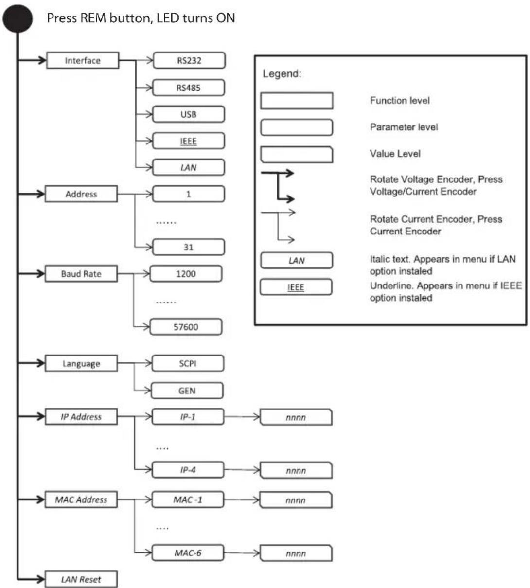
flowchart
graph TD
    A["Press REM button, LED turns ON"] --> B["Interface"]
    B --> C["RS232"]
    B --> D["RS485"]
    B --> E["USB"]
    B --> F["IEEE"]
    B --> G["LAN"]
    A --> H["Address"]
    H --> I["1"]
    H --> J["......"]
    H --> K["31"]
    A --> L["Baud Rate"]
    L --> M["1200"]
    L --> N["......"]
    L --> O["57600"]
    A --> P["Language"]
    P --> Q["SCPI"]
    P --> R["GEN"]
    A --> S["IP Address"]
    S --> T["IP-1"]
    T --> U["nnnn"]
    S --> V["......"]
    S --> W["IP-4"]
    W --> X["nnnn"]
    A --> Y["MAC Address"]
    Y --> Z["MAC-1"]
    Z --> AA["nnnn"]
    Y --> AB["......"]
    Y --> AC["MAC-6"]
    AC --> AD["nnnn"]
    A --> AE["LAN Reset"]
Fig.4-6: Communication Menu diagram
4.6.2 Exiting the Communication Menu
There are three ways to exit from REM menu:
- Press REM button.
- No action for 15sec. REM LED turns OFF. Display shows present status of power supply.
4.7 Navigating the Protection Menu
4.7.1 Introduction
The Protection Menu consists of two levels: Function and Parameter.
To navigate the Protection Menu press PROT button. The PROT GREEN LED illuminates. The function menu item appears on the display. Navigate by rotating the Voltage encoder to scroll the function level. To select the desired function, press the Encoder button next to the display. Toggle the Voltage encoder to select either UVL or UVP functions.
In the Parameter level, the Voltage display shows the function and the Current display shows the parameter. Scroll the parameter list by rotating the Current encoder. Selection of a numerical parameter is automatic and the Encoder cannot be pressed. Press only to select Foldback parameter. When parameter is accepted the display blinks once and exits to the previous level.
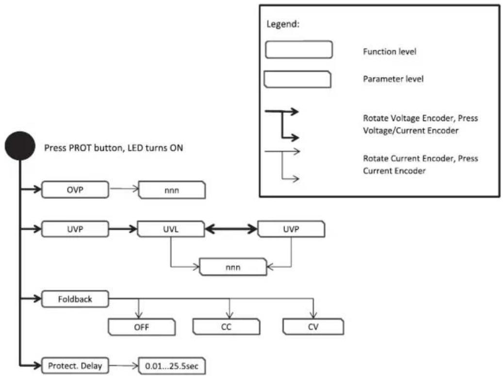
flowchart
graph TD
    A["Press PROT button, LED turns ON"] --> B["OVP"]
    B --> C["nnn"]
    A --> D["UVP"]
    D --> E["UVL"]
    E <--> F["UVP"]
    F --> G["nnn"]
    A --> H["Foldback"]
    H --> I["OFF"]
    H --> J["CC"]
    H --> K["CV"]
    A --> L["Protect. Delay"]
    L --> M["0.01...25.5sec"]
Fig.4-7: Protection Menu Navigation
4.7.2 Exiting the Protection Menu
There are three ways exit the menu:
- Press PROT button.
- No action for 15sec. PROT LED turns OFF. Display shows present status of power supply.
CHAPTER 5: LOCAL OPERATION
5.1 Introduction
This Chapter describes the operating modes that do not require programming and monitoring the power supply via its serial communication ports. USB or RS232/RS485 or by remote analog signals. Ensure that the REM LED on the front panel is Off, (indicating Local mode). If the REM LED is On, press the front panel REM button to change the operating mode to local.
- For information regarding remote analog programming refer to Chapter 6.
- For information regarding usage of the serial communication port refer to Chapter 7.
5.2 Standard Operation
The power supply has two basic operating modes: Constant Voltage mode and Constant Current mode. The mode in which the power supply operates at any given time depends on the output voltage setting, output current limit setting and the load resistance.
5.2.1 Constant Voltage Mode and Voltage Setting
- In constant voltage mode, the power supply regulates the output voltage at the selected value, while the load current varies as required by the load.
- While the power supply operates in constant voltage mode, the CV LED on the front panel illuminates.
- Adjustment of the output voltage can be made when the power supply output is enabled (Output On) or disabled (Output Off). When the output is enabled, simply rotate the Voltage encoder knob to program the output voltage. When the output is disabled, press the PREV button and then rotate the Voltage encoder to required value. The Voltage display will show the programmed output voltage for 5 seconds. Then "OFF" will appear on the Voltage display.
- Resolution can be set to Coarse or Fine adjustment. Press FINE button to select between the lower and higher resolution. The FINE LED illuminates when the resolution is set to Fine.
NOTE:
If after completing the adjustment, the display shows a different value than the setting, the power supply may be at current limit. Check the load condition and the power supply current limit setting.
NOTE:
The maximum and minimum setting values of the output voltage are limited by the Over Voltage protection and Under Voltage limit setting. Refer to sections 5.3.2 and 5.3.3 for more details.
5.2.2 Constant Current Mode and Current Setting
- In constant current mode, the power supply regulates the output current at the selected value, while the voltage varies with the load requirement.
- While the power supply is operating in Constant Current mode, the CC LED illuminates.
- Adjustment of the output current can be made when the power supply output is enabled (Output On) or disabled (Output Off). When the output is enabled, simply rotate the Current encoder knob to program the output current. When the output is disabled, press the PREV button and then rotate the Current encoder to required value. The Current display will show the programmed output current for 5 seconds. Then "OFF" will appear on the Voltage display.
- Resolution can be set to Coarse or Fine adjustment. Press the FINE button to select between the Coarse and Fine adjustment. The FINE LED illuminates when the resolution is set to Fine.
5.2.3 Automatic Crossover
When the power supply operates in Constant Voltage mode, while the load current is increased to greater than the current limit setting, the power supply will automatically switch to Constant Current mode. If the load is decreased to less than the current limit setting, the power supply will automatically switch back to Constant Voltage mode.
5.2.4 Output On/Off Control
The Output On/Off enables or disables the power supply output. The Output On/Off can be activated from the front panel using the OUTPUT button or from the communication interface. The OUTPUT button can be pressed at any time (except in Front Panel Lock mode or when a Fault condition exists). When the output is disabled, the output voltage and current fall to zero and the Voltage display shows "OFF". Press the OUTPUT button to recover from Faults such as: OVP, UVP and FOLD faults, after the Fault conditions have been removed.
5.2.5 Safe Start and Auto-Restart Modes
At turn on, the power supply AC On/Off can start at last setting of Output Voltage and Current limit with the output enabled (Auto-restart), or it can start with the output disabled (Safe mode). Press and hold the OUTPUT button to toggle between Safe start and Auto-restart modes. The Voltage display will continuously cycle between "SAFE" and "AUTO" every 3 seconds. Releasing OUTPUT button while one of the modes is displayed, selects that mode. The default setting at shipment is in Safe mode.
- Automatic Start Mode (RUED) The power supply is restored to last operation setting. Upon start-up, the output is enabled or disabled according to the last setting.
- Safe Start Mode (SAFE)
The power supply is restored to last operation setting and sets the Output to Off state. At start-up, the output is disabled and the output voltage and current are zero. To enable the output, momentarily press OUTPUT button.
5.2.6 Viewing Software Revision
Via the Front Panel Menu, it is possible view installed software revision.
-
Press MENU button. MENU (GREEN) LED illuminates. "SEE" message appears on the Voltage display.
-
Rotate Voltage encoder until "inFo" message appears on Voltage Display.
-
Press Voltage encoder. The "rE u" message appears on the display, and the installed software revision number appears on the Current display.
5.3 Alarms and Protective Functions
5.3.1 Introduction
There are several conditions that cause alarm (RED LED blinks). All alarms affect the output. When an alarm occurs, the respective fault will appear on the display and the alarm LED illuminates. It is possible that more than one fault (alarm) may be triggered but only the first will be shown on the display. If the second fault is still active when the first fault is removed, then the second fault will be displayed.
The following protective functions are incorporated in the power supply:
• OVP - Over Voltage Protection
• UVP - Under Voltage Protection
- ILC - Interlock
• FOLD - Fold Back Constant Current or Constant Voltage
• AC FAIL - AC Power shut down
• OTP - Over Temperature Protection
5.3.2 Over Voltage Protection
The OVP circuit protects the load in the event of a remote or local programming error or a power supply failure. The protection circuit monitors the voltage at the power supply sense points thus providing the protection level at the load. Upon detection of an Over Voltage condition, the power supply output will shut down.
5.3.2.1 Setting the OVP Level
The OVP can be set when the power supply output is Enabled (On) or Disabled (Off). The minimum setting level is 5% above the output voltage, or the value in Table 5-1, whichever is higher. The maximum setting level is shown in Table 5-1.
- Press PROT button. PROT (GREEN) LED illuminates. "OUP" message appears on the Voltage display.
- Press Voltage encoder. "OUP" message appears on the Voltage display and the Current display shows OVP setting level.
- Rotate the Current encoder to adjust the OVP level.
- Press PROT button twice or wait 15 sec. to return display to its previous state and then PROT LED turns OFF.
| Min. OVPMax. OVPModel | |
| 0.5V12.0V10V | |
| 1.0V24.0V20V | |
| 2.0V40.0V36V | |
| 5.0V66.0V60V | |
| 5.0V110.0V100V |
Table 5-1: Maximum/Minimum OVP setting levels
5.3.2.2 Resetting the OVP Circuit
To reset the OVP circuit after activation:
-
Reduce the power supply Output Voltage setting below the OVP set level.
-
Ensure that the load and the sense wiring is connected properly.
-
Four methods to reset the OVP circuit.
-
Press OUTPUT button.
- AC recycle.
• On/Off recycle by analog control (Interlock). - Send communication command to enable output.
5.3.3 Under Voltage Protection and Under Voltage Limit
The UVL function prevents output voltage setting below UVL set value. The UVP function prevents power supply operation if output voltage is below UVP set value. Upon detection of an Under Voltage condition, the power supply output will shut down. The UVL prevents adjustment of the output voltage below a certain limit. The combination of UVP/UVL and OVP functions, allows the user to create a protection window for sensitive load circuitry.
5.3.3.1 Setting the UVP/UVL Mode and Level
The UVP/UVL can be set when the power supply output is Enabled (On) or Disabled (Off). UVL and UVP setting values are limited at the maximum level to approximately 5% below the Output Voltage setting. Attempting to adjust the value above this limit will result in no response to the adjustment attempt. The minimum value setting is zero. If UVP setting is below 5% of rated output voltage, UVP will act as UVL.
- Press PROT button. PROT (GREEN) LED illuminates. Current display shows "UUP" message.
- Press Current Encoder. Voltage Display shows "UUP" or "UUL" message, Current display shows setting level.
- Rotate the Voltage encoder to set "UUP" or "UUL", and then press the encoder. The display blinks once.
- Rotate the Current encoder to adjust the level.
- Press PROT button twice or wait 15 sec. to return display to its previous state and then PROT LED turns OFF.
5.3.3.2 Activated UVP Alarm
When the UVP is activated the power supply output shuts down. The Voltage and Current display shows "UUP FA IL" and the PROT red LED blinks.
5.3.4 Foldback Protection
Foldback protection will shut down the power supply output if power supply operation mode crosses over from CC to CV or from CV to CC, according to selected operation mode. There are three states of foldback protection. OFF (default), CV, CC.
5.3.4.1 Setting the Foldback Protection
The Foldback can be set when the power supply output is Enabled (On) or Disabled (Off).
- Press PROT button. PROT (GREEN) LED illuminates. The "DUP" message appears on the Voltage display.
- Rotate Voltage encoder until "FOLD" message appears on Voltage display.
- Press Voltage encoder. "FOLd" message appears on Voltage Display, and on Current display shows "OFF" or "CC" or "CU" setting mode.
- Rotate the Current encoder to adjust required mode and press to select. Display returns to the previous level.
- Press PROT button to return display to its previous state (PROT LED turns OFF).
5.3.4.2 Activated FOLD Alarm
When the Foldback is activated the power supply output shuts off. The Voltage and Current display shows "FOLD FA IL" and the PROT red LED blinks.
5.3.5 Protection Delay
A delay can be set from between the time when a fault is detected and the output is disabled. It relates only in cases of UVP and Foldback protection.
NOTE:
UVP protection delay = 500ms + delay setting.
5.3.5.1 Setting the Protection Delay
- Press PROT button. PROT (GREEN) LED illuminates. The "DUP" message, appears on the Voltage display.
- Rotate Voltage encoder until "Pr - dL" message appears on Voltage display, and then press the Encoder.
- The "Pr.dL" message appears on the Voltage Display. The Current display shows the value in seconds.
- Rotate the Current encoder to adjust the delay. Protection delay setting range is 0...25.5sec.
- Press Current encoder to select. Display blinks once and exists to the previous level.
- Press PROT button once to return display to the previous state and PROT LED turns off.
5.3.6 Over Temperature Protection
The OTP circuit shuts down the power supply before the internal components can exceed their safe internal operating temperature. When an OTP shutdown occurs, the display shows "OEP FAIL" and the PROT LED blinks. Resetting the OTP circuit can be automatic (non-latched) or manual (latched) depending on if he power supply is in Safe or Automatic restart mode.
- Safe start mode: The power supply stays off after the OTP condition has been removed. The display continue to shows "O EP FAIL" and the PROT LED continues to blink. To reset the OTP circuit, press OUTPUT button (or send Output Enable command).
- Auto-restart mode: The power supply recovers to it's last setting automatically after the OTP condition is removed.
5.3.7 AC Fail Alarm
The AC Fail alarm indicates whether the AC input has been discounted or shut down. When any of these faults occur, the display shows "AC FR IL". Output power is disabled, and the PROT LED blinks.
- Safe start mode: The power supply returns to "OFF", after the AC power returns.
- Auto-restart mode: The power supply recovers to it's last setting automatically when AC power returns.
5.4 Series Operation
Power supplies of the same model can be connected in series to obtain increased output voltage. Split connection of the power supplies gives positive and negative output voltage.
5.4.1 Series Connection for Increased Output Voltage
Two units are connected so that their outputs are summed. Set the current limit of each power supply to the maximum that the load can handle without damage. It is recommended that diodes be connected in parallel with each unit output to prevent reverse voltage during start up sequence or in case one of the units shuts down. Each diode should be rated to at least the power supply rated output voltage and output current. Refer to Fig.5-1 and Fig.5-2 for series operation with local and remote sensing.
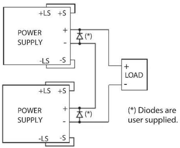
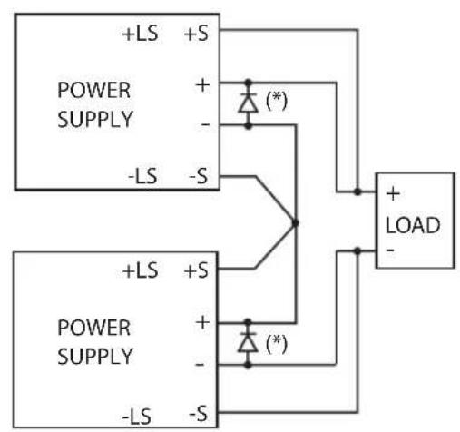
flowchart
graph TD
    A["POWER SUPPLY"] -->|+/-| B["Diode (*)"]
    C["POWER SUPPLY"] -->|-/-| B
    B --> D["+ LOAD"]
    style A fill:#f9f,stroke:#333
    style C fill:#f9f,stroke:#333
    style D fill:#ccf,stroke:#333
Fig.5-1: Series connection, local sensing Fig.5-2: Series connection, remote sensing
5.4.2 Series Connection for Positive and Negative Output Voltage
In this mode, two units are configured as positive and negative output. Set the current limit of each power supply to the maximum that the load can handle without damage. It is recommended that diodes be connected in parallel with each unit output to prevent reverse voltage during start-up or in case one of the units shuts down. Each diode should be rated to at least the power supply rated output voltage and output current. Refer to Fig.5-3 for this operating mode.
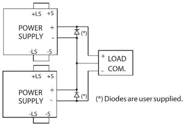
Fig.5-3: Series connection for positive/negative output voltages
5.4.3 Remote Programming in Series Operation
Programming by external voltage: The analog programming circuits of this power supply are referenced to the negative Sense potential. Therefore, the circuits used to control each series connected unit must be separated and floated from each other. Refer to section 6.4
Using the SO function and PS_OK signal: The Shut Off and PS_OK circuits are referenced to the isolated interface common, IFC_COM (J3-7). The IFC_COM terminals of the units can be connected to obtain a single control circuit for the power supplies connected in series.
Programming by external resistor : Programming by external resistor is possible. Refer to section 6.5 for details.
Programming via the Serial Communication port (RS232/RS485, USB):
The Communication port is referenced to the IFC_COM which is isolated from the power supply output potential. Therefore power supplies connected in series can be chained using the Remote-In and Remote-Out connectors. Refer to Chapter 7 for details.
5.5 Parallel Operation
5.5.1 Introduction
Up to six units of the same Voltage and Current rating can be connected in parallel to provide up to six times the output current capability. One of the units operates as a master and the remaining units are slaves. The slave units are analog programmed by the master unit. In remote digital operation, only the master unit can be programmed by the computer while the slave units may be connected to the computer for voltage, current and status readback only.
The Master and Slave modes are stored in the power supply EEPROM when the AC power is turned off. The system will return to the Master/Slave mode upon re-application of AC power.
There are two methods to configure multiple supplies for parallel operation (basic and advanced). Refer to Section 5.5.2 and to Section 5.5.3 for detailed explanation. Parallel modes are selected via Front Panel menu. Refer to table 5-2.
| Subsystem Level Function Level Parameter Level | |||||
| Description Display | Function Display Description Display | ||||
| Parallel Operating Mode | PrLL | Host /Basic Slave / Advanced Slave | HOST | Single power supply | H1 |
| Master | H2..H6 | ||||
| SLUE | Slave (Basic) | SL | |||
| Slave (Advanced) | SLAd | ||||
Table 5-2. Parallel subsystem menu
| Display | Operating Mode |
| H1 | Single unit (default) |
| H2 | Master unit with 1 Slave unit |
| H3 | Master unit with 2 Slave units |
| H4 | Master unit with 3 Slave units |
| H5 | Master unit with 4 Slave units |
| H6 | Master unit with 5 Slave units |
| SL | Slave unit (Basic mode) |
| SLAd | Slave unit (Advanced mode) |
Table 5-2.1: Operation Setting Mode
5.5.2 Basic Parallel Operation
In this method, setting the units as Master and Slaves is made by the rear panel J1 connections and setup via Front Panel. Each unit displays its own output current and voltage. To program the load current, the Master unit should be programmed to the total load current divided by the number of units in the system. The master and slave units operate in a Daisy-Chain connection configuration. For further details about Daisy-chain connection refer to section 5.6. Refer to the following procedure to configure multiple supplies for basic parallel operation.
5.5.2.1 Master Unit Set Up
During operation, the master unit operates in CV mode, regulating the load voltage at the programmed output voltage. Connect the sensing circuit to local or remote sensing as shown in Fig.5-4 or Fig.5-5. Front Panel Main Menu Parallel mode is "H I" as default.
- Press MENU button.
- Rotate Voltage encoder until "PrLL" appears on Voltage display, then press Voltage encoder.
- Rotate Current encoder until "H1" appears.
- Press Current encoder to select "H I", the display blinks once and returns to previous menu level.
- Set the master unit output voltage to the desired voltage. Program the current limit to the desired load current limit, divided by the number of parallel units.
- If there is more than one Slave unit connected to the Master, then set the PS_OK signal delay of the Master to 200msec. Refer to section 5.7.4 Power Supply OK Signal.
5.5.2.2 Slave Unit Set Up
When Slave mode is selected the power supply enters Current programming mode via external Voltage. Voltage and Current programming setting values are set to 105% of range. During operation the slave units operate as a controlled current source following the master output current. It is recommended that the power system is designed so that each unit supplies up to 95% of its current rating. This helps reduce imbalance which may occur by cabling and connections voltage drop.
- Press MENU button
- Rotate Voltage encoder until "P-LL" appears on Voltage display, then press Voltage encoder.
- Rotate Current encoder until "5L" appears.
- Press Current encoder to select "SL". Display blinks once and returns to previous display.
- For wiring instructions, refer to Fig.5-4: Parallel connection with local sensing or Fig.5-5: Parallel connection with remote sensing.
5.5.2.3 Setting Over Voltage Protection
The master unit OVP should be programmed to the desired OVP level. In slave mode, the power supply is set to maximum as default.
5.5.2.4 Setting Foldback Protection
Foldback protection, if desired, may only be used with the master unit. When the master unit shuts down it programs the slave units to zero output voltage.
5.5.2.5 Connection to Load
In parallel operation, power supplies can be connected in local or remote sensing. Refer to Fig.5-4 and 5-5 for typical connections of parallel power supplies. The figures show connection of two units, however the same connection method applies for up to 6 units.
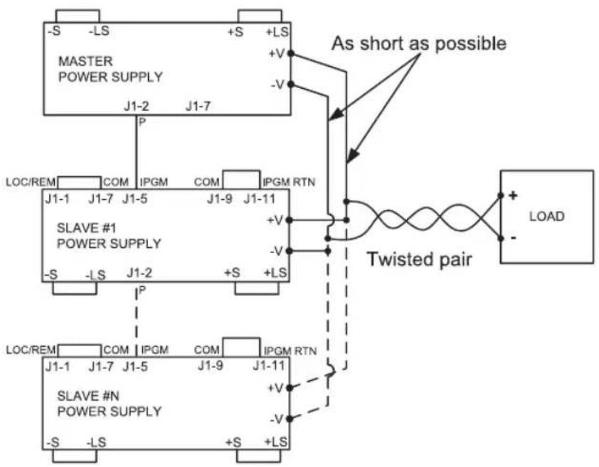
flowchart
graph TD
    A["MASTER POWER SUPPLY"] -->|+V -V| B["As short as possible"]
    C["SLAVE #1 POWER SUPPLY"] -->|+V -V| B
    D["SLAVE #N POWER SUPPLY"] -->|+V -V| B
    E["LOC/REM"] --> F["COM IPGM"] --> G["IPGM RTN"]
    H["LOAD"] --> I["Swisted pair"]
    style A fill:#f9f,stroke:#333
    style C fill:#f9f,stroke:#333
    style D fill:#f9f,stroke:#333
    style E fill:#f9f,stroke:#333
    style F fill:#ccf,stroke:#333
    style G fill:#ccf,stroke:#333
    style H fill:#ccf,stroke:#333
    style I fill:#ccf,stroke:#333
Fig.5-4: Parallel connection with local sensing
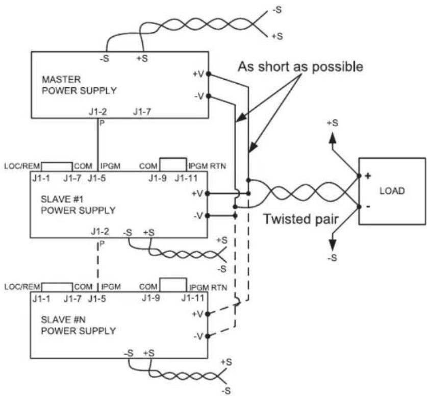
flowchart
graph TD
    A["MASTER POWER SUPPLY"] -->|S +V| B["As short as possible"]
    C["SLAVE #1 POWER SUPPLY"] -->|P J1-2 -S +V| D["Twisted pair"]
    E["SLAVE #N POWER SUPPLY"] -->|P J1-1 -S +V| D
    D --> F["LOAD"]
    style A fill:#f9f,stroke:#333
    style C fill:#f9f,stroke:#333
    style E fill:#f9f,stroke:#333
    style B fill:#ccf,stroke:#333
    style D fill:#ccf,stroke:#333
    style F fill:#ccf,stroke:#333
Fig.5-5: Parallel operation with remote sensing
CAUTION:
Make sure that the connection between - Vo terminals is reliable to avoid disconnection during operation. Disconnection may cause damage to the power supply.
NOTE:
With local sensing it is important to minimize the wire length and resistance. Also the positive and negative wire resistance should be as close as possible to each other to achieve current balance between power supplies.
5.5.3 Advanced Parallel Operation
In Advanced Parallel operation the master unit displays the total current of all units connected in Parallel. The slave units display "ON SLUE". The master and slave units operate in a Daisy-Chain connection configuration. For further details about Daisy-chain connection refer to section 5.6.
In the Advanced Parallel mode, the total current is programmed and reported by the master unit. The Current display accuracy is 2%+/- 1 count. In cases where higher accuracy is required, it is recommended to use Basic Parallel operation mode.
5.5.3.1 Master Unit Set Up
During operation, the master unit operates in CV mode, regulating the load voltage at the programmed output voltage. Connect the sensing circuit to local or remote sensing as shown in Fig.5-4 or Fig.5-5.
- Press MENU button.
- Rotate Voltage encoder until "PrLL" appears on Voltage display, then press Voltage encoder.
- Rotate Current encoder and select required 'n' value (from 2-6) for example, "H∃". The display blinks once and returns to previous level. Refer to Table 5-2.1.
- Set the master unit output voltage to the desired voltage. Program the current limit to the desired load current limit, divided by the number of parallel units.
- Recycle AC power.
- If there is more than one Slave unit connected to the Master, then set the PS_OK signal delay of the Master to 200msec. Refer to section 5.7.4 Power Supply OK Signal.
5.5.3.2 Slave Unit Set Up
When Advanced Slave mode is selected the power supply enters Current programming mode via external Voltage. Voltage and Current programming setting values are set to 105% of range. During operation the slave units operate as a controlled current source following the master output current. It is recommended that the power system is designed so that each unit supplies up to 95% of its current rating. This helps reduce imbalance which may occur by cabling and connections voltage drop.
When a unit is programmed to Advanced Slave mode it enters Remote mode with Local Lockout. In this mode, Front panel controls are disabled to prevent accidental setting change except Menu parallel setting and factory reset. Communication commands are disabled. Power supply responds only upon query.
- Press MENU button.
- Rotate Voltage encoder until "PrLL" appears on Voltage display, then press Voltage encoder.
- Rotate Current encoder until "SLAd" appears.
- Press Current encoder to select "SLAd". Display blinks once and returns to previous level.
- Recycle AC power.
- For wiring instructions, refer to Fig.5-4: Parallel connection with local sensing or Fig.5-5: Parallel connection with remote sensing and Section 5.6: Daisy-Chain connection.
NOTE:
To release units from Advanced mode select "H I".
5.6 Daisy-Chain Connection
It is possible to configure a multiple power supply system to shut down all units when a fault condition occurs in one of the units. When the fault is removed, the system recovers according to a preset state: Safe start mode or Automatic restart.
Set signal "SO" to positive logic via Front panel (refer to section 5.7.1). If a fault occurs in one of the units it's "PS_OK" signal will be set to low level and the display will indicate the fault. The other units will shut off and their displays will indicate "SO". When the fault condition is removed, the units will recover to their last setting according to their respective Safe start or Auto-restart setting.
Fig.5-6 shows connection of three units, however the same connection method applies to systems with more units.
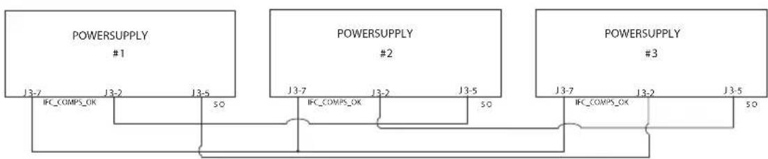
flowchart
graph TD
    A["POWERSUPPLY #1"] -->|J3-7 IFC_COMPS_OK| B["POWERSUPPLY #2"]
    B -->|J3-7 IFC_COMPS_OK| C["POWERSUPPLY #3"]
    C -->|J3-7 IFC_COMPS_OK| B
    B -->|J3-5 SO| C
    A -->|J3-2 IFC_COMPS_OK| B
    B -->|J3-2 IFC_COMPS_OK| C
    C -->|J3-5 SO| B
    B -->|SO| C
Fig.5-6: Daisy-Chain connection
5.7 Rear Panel (J3 Connector) Functions and Settings
| Subsystem Level | Display | Function Level | Display Parameter Level Display Description | |||
| Rear Panel | r.PAN | Interlock | 1LC | Enable (ON) | ON | Enable/Disable interlock function (Analog ON/OFF) |
| Disable (OFF) | OFF | |||||
| Shut OFF | 50 | Positive | POS | Positive (polarity) same as PS_OK signal | ||
| Negative | NEG | |||||
| Programmed PIN 1 | Pin 1 | High | Hi | Open collector | ||
| Low | Lo | |||||
| Programmed PIN 2 | Pin2 | High | Hi | Open collector | ||
| Low | Lo | |||||
Table 5-3: Rear panel subsystem menu
5.7.1 External Shut Off Function
SO signal serves as Output Shut Off. It is an optically isolated signal from the power supply output. Connection to the signal is made via pin J3-5 (Shut Off) and pin J3-7 (IFC_COM). The SO pin accepts a 2.5V to 15V signal or Open-Short contact to disable or enable the power supply output. The SO function will be activated only when a transition from On to Off is detected after applying AC power to the unit. Thus, in Auto start mode, the output will be enabled after applying AC power, even if SO is in Off level. After On to Off transition is detected, the SO will enable or disable the power supply output according to the signal level or the short/open applied to J3. When the external SO is triggered, the power supply will display "50" on the voltage display but the PROT LED will not illuminate.
The external shutdown is useful when using the power supply as part of a larger test system in which digital or analog control is required or in "Daisy-Chain".
The SO control logic can be selected via the Front panel as follows:
- Press MENU button. MENU (GREEN) LED illuminates. "SEE" message appears on the Voltage display and "r-PAH" message appears on the Current display.
- Press Current encoder. The "50" message appears on the Current display.
- Press the Current encoder again. The "50" message appears on the Voltage display. Parameter "POS" or "NEG" appears on the Current display.
- Rotate and press the Current encoder to select the required parameter.
- For signal details refer to Table 5-4.
SO logic SO signal level (J3-5 - J3-7) Output status
| Positive (as PS_OK) (default) 2-15V or Open | On |
| 0-0.6V or Short | Off 50 |
| Negative 2-15V or Open | Off 50 |
| 0-0.6V or Short | On |
Table 5-4: SO logic selection
5.7.2 Interlock Function - Analog On/Off. (Enable/Disable)
Interlock signal serves as Output Enable/Disable via switch or relay. Use the Interlock function to enable or disable the output as emergency shutoff or door open switch. It is an optically isolated signal from the power supply output. Connection to the signal is made via pin J3-4 (ILC) and pin J3-7 (IFC_COM).
The ILC control logic can be selected via the Front panel as follows:
- Press MENU button. MENU (GREEN) LED illuminates. "SEE" message appears on the Voltage display. "r.PAN" message appears on Current display.
- Press Current encoder and the "IL E" message appears on the display.
- Press Voltage encoder and "ILC" message appears on the display. The parameters "OFF" or "ON" appear on the Current encoder display.
- Rotate and press the Current encoder to select desired parameter.
- For signal details refer to Table 5-5.
| Front Panel ILC Setting | ILC Input | Power Supply Output | Display Alarm LED | |
| OFF - Default Open or Short On Voltage/Current Off | ||||
| ON | Open Off | EnR | Blinking | |
| Short On Voltage/Current Off | ||||
Table 5-5: Interlock functions and settings
CAUTION:
To prevent possible damage to the unit, do not connect any of the Enable /Disable inputs to the positive or negative output potential.
NOTE:
Safe Start mode - If the Interlock fault condition clears while units are in safe start mode, the power supply returns to Off mode.
Auto Restart mode - The output will automatically return to previous settings.
5.7.3 Auxiliary Programmed Function Pin 1 and Pin 2
The programmed signal Pin 1 (J3-1) and Pin 2 (J3-6) are open collector, maximum input voltage 25V and maximum sink current 100mA, and can be controlled via Front panel or software.
Pin 1 or Pin 2 settings are made as follows:
- Press MENU button. MENU (GREEN) LED illuminates. The "r .PAN" message appears on the Current display.
- Press Current encoder and the "IL E" message appears on the Voltage display.
- Rotate Voltage encoder until "P in1/P in2" message appears on display. Press Encoder to select the desired Pin.
- Voltage display shows the selected Pin number.
- Rotate the Current encoder to toggle between "H1" (High) or "L0" (Low).
- Press Current encoder to select desired parameter.
- Press MENU button twice to return display to it's previous state. MENU LED turns OFF.
CAUTION:
Do not connect Pin 1 and Pin 2 to a voltage source higher than 25V. Always connect Pin 1 and Pin 2 to the voltage source with a series resistor to limit the sink current to less than 100mA.
5.7.4 Power Supply OK Signal
PS_OK signal indicates fault condition in the power supply. It is a TTL signal output at J3-2, referenced to IFC_COM at J3-7 (Isolated Interface Common). When a fault condition occurs, PS_OK level is low, with maximum sink current of 1mA. When no fault condition occurs, PS_OK level is high with maximum source current of 2mA. All conditions when output status is disabled sets PS_OK to low level.
The PS_OK signal at high level can be delayed via Front panel setting or software. This function is used to prevent signal rise before output reaches set value.
PS_OK delay setting:
- Press MENU button. MENU (GREEN) LED illuminates. The "r .PAN" message appears on the Current display.
- Press Current encoder, "ILE" message appears on the Voltage Display.
- Rotate Voltage encoder until "PSd" message appears and press Encoder.
- Parameter delay time in mSec appears on the Current display
- Rotate the Current encoder to adjust the setting level. PS_OK delay range is from 0 to 9999mSec.
- Press Current encoder to select desired level.
- Press MENU button twice to return display to it's previous state. MENU LED turns OFF.
5.8 Rear Panel (J1 Connector) Functions
5.8.1 CV/CC Signal
The CV/CC signal indicates the operating mode of the power supply. Constant Voltage or Constant Current. CV/CC signal is an open collector output with a 30V parallel zener, at J1-8, referenced to the COM at J1-7 (connected internally to the negative sense potential). When the power supply operates in Constant Voltage mode, CV/CC output is open. When the power supply operates in Constant Current mode, CV/CC signal output is low (0-0.6), with maximum 10mA sink current.
CAUTION:
Do not connect CV/CC signal to a voltage source higher than 30VDC. Always connect CV/CC signal to the voltage source with a series resistor to limit the sink current to less than 10mA.
5.9 Parameter Setting Memory
Power Supply has four memory configuration modes:
| Subsystem Level | Display | Function Level | Display | Parameter Level | Display Description |
| Memory | rEtno | SAVE | SAVE | 1...4 | 1...4 Save setting in non violate memory |
| RECALL | rECL | 1...4 | 1...4 Recall setting in non violate memory | ||
| RST | rSt | YES | YES Reset setting | ||
| FRST | F.rSt | YES | YES Set factory default setting |
Table 5-6: Parameter Setting Memory
5.9.1 Default Setting
For factory default parameters refer to Table 5-7.
-
Press MENU button. MENU (green) LED illuminates. "SEE" message appears on the Voltage display.
-
Rotate Voltage encoder until "FENIO" message appears on Voltage display.
-
Press Voltage encoder. "SAVE" message appears on Voltage Display.
-
Rotate Voltage encoder until "F .r5 E" message appears on Voltage display.
-
Press Voltage encoder. "E-SE" message appears on Voltage Display, and "YES" appears on Current display.
-
Press the Current encoder "HOLD" Message appears on the display for 1sec. The display blinks once and returns to previous level.
-
Press MENU button twice to return display to previous state, MENU LED turns OFF.
NOTE:
No response for FRST command. After this command the power supply loses communication because of communication setting change.
5.9.2 Reset
For Reset parameters refer to Table 5-7.
-
Press MENU button. MENU (green) LED illuminates. "SEE" message appears on the Voltage display.
-
Rotate Voltage encoder until "EID" message appears on Voltage display.
-
Press Voltage encoder. "SAVE" message appears on Voltage Display.
-
Rotate Voltage encoder until "-5E" message appears on Voltage display.
-
Press Voltage encoder. "RSE" message appears on Voltage Display. "YES" appears on the Current display.
-
Press the Current encoder, display blinks and returns to previous level.
-
Press MENU button twice to return display to previous state, MENU LED turns OFF.
5.9.3 Last Setting Memory
Memory stores last set parameters when AC switch is turned off.
For last set parameters refer to Table 5-7.
5.9.4 Save <1..4>
This command saves the present state of the power supply to a specified location in memory (refer to Table 5-7). Up to 4 states can be stored. Storage locations 1 through 4 are in nonvolatile memory.
Save Front panel setting:
- Press MENU button. MENU (green) LED illuminates. "SET" message appears on the Voltage display.
- Rotate Voltage encoder until "TET0" message appears on Voltage display.
- Press Voltage encoder. "SAVE" message appears on Voltage display.
- Press Voltage encoder. "SAVE" message appears on Voltage display. Numbers "1..4" appear on Current display.
- Rotate the Current encoder to select required number value and then press the Current encoder. Display blinks and returns to previous level.
5.9.5 Recall <1..4>
This command recalls the present state of the power supply from a specified location in memory (refer to Table 5-7). Up to 4 states can be stored. Storage locations 1 through 4 are in nonvolatile memory.
Recall front panel setting:
- Press MENU button. MENU (green) LED illuminates. "5E" message appears on the Voltage display.
- Rotate the Voltage encoder until "TET0" message appears on Voltage display.
- Press Voltage encoder. "rECL" message appears on Current display.
- Press Current encoder. Numbers "1..4" appear on Current display.
- Rotate the Current encoder to select required number value and then press the Current encoder. Display blinks and returns to previous level.
| Parameter Factory Default | Resetting Last setting | Save & Recall | ||
| Output Status OFF OFF + + | ||||
| Voltage Set-point 0V 0V + + | ||||
| Current Set-point MAX 0A + + | ||||
| Fold Back mode OFF OFF + + | ||||
| Over Voltage Protection OVP | MAX MAX + + | |||
| Under Voltage Level/ Protection mode | OFF (UVL) | OFF (UVL) | ++ | |
| Under Voltage Level/ Protection level | 0V 0V + + | |||
| Auto Start Mode | SAFE | SAFE | ++ | |
| Control pin 1 | 1 | 1 | ++ | |
| Control pin 2 | 1 | 1 | ++ | |
| Input Trigger Source | EXT | EXT | + | - |
| Protection Delay | 0mS | 0mS | ++ | |
| Voltage Programming Mode | Digital - | + | - | |
| Current Programming Mode | Digital - | + | - | |
| Programming and Monitor Range | 5V | - | + | - |
| Current Share Mode {Master|Slave} | (Master H1) | - | + | - |
| Interlock (Inhibit) | OFF (disabled) | OFF (disabled) | + | - |
| Shutdown Logic | 1 (positive) | - | + | - |
| Remote mode | LOC LOC + + | |||
| Communication Mode | RS232 | - | + | - |
| Address | 6 | - | + | - |
| Baud Rate | 9600 | - | + | - |
| Language | SCPI - | + | - | |
| Lock/unlock front panel | Unlock | - | + | - |
| LIST and WAVE subsystems | OFF | OFF | - | - |
| Program Step | AUTO | AUTO (COUNT 1) | - | - |
| Trigger Out | OFF OFF + + | |||
| PS_OK delay | 0mS | 0mS + + | ||
| Enable registers | Clear | Clear | - | - |
| Event registers | Clear | Clear | - | - |
Table 5-7: Memory parameters.
CHAPTER 6: REMOTE ANALOG PROGRAMMING
6.1 Introduction
The Rear Panel connector J1 allows the user to program the power supply output voltage and current limit with an analog device. J1 also provides monitoring signals for output voltage and output current. The programming range and monitoring signals range can be selected between 0-5V or 0-10V using the Front Panel Menu Subsystem Level.
| Subsystem Level | Display | Function Level | Display | Parameter Level Display | Description | |
| SET | SET | Voltage limit source | UOLT | Front Panel (Digital) | F.PAN | Parameter settings in Analog/ Digital control mode, Voltage channel. |
| Ext. Voltage | E.VOL | |||||
| Ext. Resist. | E.rES | |||||
| Current limit source | Curr | Front Panel (Digital) | F.PAN | Parameter settings in Analog/ Digital control mode, Current channel. | ||
| Ext. Voltage | E.VOL | |||||
| Ext. Resist. | E.rES | |||||
| Source and monitor range | rRNG | 5/10 (V/KΩ) range | 5 | Control by external Voltage/ Resistor, Range 5/10 |
Table 6-1: MENU. Analog Programming Setting
CAUTION:
COM (J1-7,9) and VPGM_RTN (J1-12) terminals of J1 are connected internally to the -Sense potential (-S). Do not connect these terminals to any potential other than -Sense (-S), as it may damage the power supply.
6.2 Local/Remote Analog Control
Contact J1-1 (Fig.4-3, item 1) accepts TTL signal or Open-Short contact (Referenced to J1-7,9) to select between Local or Remote Analog programming of the output voltage and current limit. In Local mode, the output voltage and current limit can be programmed via the front panel Voltage and Current encoders or via the Communication interface. In Remote Analog mode, the output voltage and current limit can be programmed by analog voltage or by programming resistors via J1 contacts 6 and 5. Refer to Analog Programming Setting Table 6-2.
6.3 Local/Remote Analog Indication
Contact J1-4 (Fig.4-3, item 4) is an open collector output that indicates if the power supply is in Local mode or in Remote Analog mode. To use this output, connect a pull-up resistor to a voltage source of 30Vdc maximum. Choose the pull-up resistor so that the sink current will be less than 5mA when the output is in low state. J1-4 signal will be low if J1-1 is low and at least one of Analog control modes are selected. Refer to Analog Programming Setting Table 6-2.
| J1-1 LOC/REM SELECT Front Panel selection Front Panel selection J1-4 LOC/REM MON | |||
| OPEN"1" | Not applicable Not applicable Open | ||
| TTL "0" or Short | F.PAN F | .PAN | Open |
| E.UOL or E.rES | F.PAN | 0~0.6V | |
| F.PAN | E.UOL or E.rES 0~0.6V | ||
| E.UOL or E.rES E | UOL or E.rES 0~0.6V | ||
Table 6-2: Local/Remote Analog Control and Indication
6.4 Remote Voltage Programming of Output Voltage and Current
Remote Programming settings are as follows:
- For Voltage Analog Programming wiring refer to Fig.6-1.
- Short pins J1-1 to J1-7.
- Press MENU button. MENU (GREEN) LED illuminates. "SET" message appears on Voltage display.
- Press Voltage encoder. "UOLE" message appears on Voltage Display and "Curr" appears on the Current display.
- Press Voltage encoder to select programming of the Output Voltage, or press Current encoder to select programming of the Output Current.
- The selected function appears on the Voltage display. Parameter "F .PAN" or "E.UOL" or "E-ES" appears on the Current display.
- Rotate and press the Current encoder to select "E .UOL".
- "UOLE" message appears on Voltage Display and "Curr" appears on the Current display.
- Rotate Voltage encoder until "¬ANO" appears on display. Press on the relevant Encoder.
- "rANG" appears on Voltage display and "S" (5V) or "I0" (10V) appears on Current display.
- Rotate and press the Current encoder to select the desired programming Voltage range.
- Press MENU button twice to return display to it's previous state. MENU LED turns OFF
CAUTION:
To maintain the isolation of power supply and prevent ground loops, use an isolated programming source when operating the power supply via remote analog programming at J1 connector.
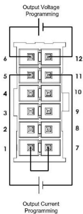
Fig.6-1: J1-Remote Voltage Programming Connection
6.5 Remote Resistor Programming of Output Voltage and Output Current
For resistive programming, internal current sources, for output voltage and/or output current control, supply 1mA current through external programming resistors connected between J1-6 and J1-12 and between J1-5 and J1-1, J1-7 & J1-11. The voltage across the programming resistors is used as a programming voltage for the power supply. Resistance of 0\~5Kohm or 0\~10Kohm can be selected to program the output voltage and current limit from zero to full scale. A variable resistor can control the output over the entire range, or a combination of variable resistors and series/parallel resistors can control the output over restricted portion of the range.
Remote Programming settings as follows:
- For Resistor Analog Programming wiring refer to Fig.6-2.
- Short pins J1-1 to J1-7.
- Press MENU button. MENU (GREEN) LED illuminates. "SEE" message appears on Voltage display.
- Press Voltage encoder. "UOLE" message appears on Voltage Display and "Curr" appears on the Current display.
-
Press on the Voltage encoder to select programming the Output Voltage, or Press Current encoder to select programming of the Output Current.
-
The selected function appears on the Voltage display. Parameter "F .PAN" or "E.UOL" or "E-ES" appears on the Current display.
-
Rotate and press the Current encoder on to select "E .rES".
-
"UOLE" message appears on Voltage Display and "Curr" appears on the Current display.
-
Rotate Current encoder until "rANG" appears on the display. Press on the relevant Encoder.
-
"RANG" appears on Voltage display and "S" (5K) or "I0" (10K) appears on Current display.
-
Rotate and press the Current encoder to select the desired programming Resistance range.
-
Press MENU button twice to return display to the previous state. MENU LED turns OFF.
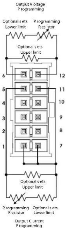
Fig.6-2: J1-Remote Resistor Programming Connection
NOTES:
- In Remote analog mode: the output voltage cannot be set by the Voltage encoder.
The output voltage limit is set to 5% over the model-rated maximum value. The output Current limit is set by the Current encoder to 5% over the model-rated maximum value. - The power supply will operate within the extended range, however it is not recommended to operate the power supply over its voltage and current rating and performance is not guaranteed.
- Communication: In Remote analog mode, power supply parameters can be programmed and read back via the Communication port except output voltage and current settings.
- To maintain the temperature stability specification of the power supply, the resistors used for programming should be stable and low noise resistors, with a temperature coefficient of less than 50ppm.
- Radiated emissions, FCC requirements: FCC requirements for radiated emissions, use a shielded cable for the analog control signals. In cases using a non-shielded cable, attach an EMI ferrite suppressor to the cable, as close as possible to the power supply.
- Front panel PREV button: Use PREV button to display the output voltage and current settings defined by the Encoders or Communication.
6.6 Programming Monitoring of Output Voltage (V\_MON) and Current (I\_MON)
The J1 connector, located on the rear panel provides analog signals for monitoring the output voltage and output current. Selection of the voltage range between 0-5V or 0-10V is made via Front Panel.
The monitoring signals represent 0 to 100% of the power supply output voltage and output current. The monitor outputs have 500 ohm series output resistance.
Ensure that the sensing circuit has an input resistance of greater than 500 Kohm or accuracy will be reduced.
Range selection as follows:
- Press MENU button. MENU (GREEN) LED illuminates. "SEE" appears on Voltage display.
- Press Voltage encoder. "UOLE" message appears on Voltage Display and "Curr" appears on the Current display.
- Rotate Voltage encoder until "r-ANG" appears on display. Press on the relevant Encoder.
- "r-ANG" appears on Voltage display and "S" (5V) or "10" (10V) appears on Current display.
- Rotate and press the Current encoder to select the desired monitoring Voltage range.
- Press MENU button twice to return display to the previous state. MENU LED turns OFF.
CHAPTER 7: Serial RS232/RS485 and USB Interface
7.1 Introduction
This chapter describes the set-up, operation, commands and communication protocol of Z^+ power supplies via serial communication interfaces: RS232, RS485 or USB.
7.2 Configuration
| Function Level Display | Parameter Level | Display Description | ||
| Interface | INTF | 232 | 232 | |
| 485 | 485 | |||
| USB | USB | |||
| LAN | LAN | Available only if IEEE or LAN option installed | ||
| IEEE | IEEE | |||
| Address | Adr | 1....31 | 1...31 | |
| Baud Rate | bAUD | 1200..57600 | 57.6 | |
| Language | LANG | SCPI | SCPI | |
| GEN | GEN | |||
| IP Address | IP | IP1---IP4 | IP 2 1096 | Available only if LAN option installedMAC Address |
| iAC | MAC1-MAC6 | iAC6 3345 | ||
| LAN Reset | rSt | Yes | YES | |
Table 7-1: Front panel setup
7.2.1 Default Setting
Refer to Table 5-7: Memory parameters.
7.2.2 Address Setting
The power supply address can be set to any address between 1 and 31.
- Press REM button. The REM LED illuminates. "Rdr" message appears on the Current display.
- Press Current encoder. Voltage display shows "Rdr" and Current display shows present address.
- Rotate the Current encoder to select required address.
- Press Current encoder to enter selected parameter to memory.
- When parameter is accepted the display blinks once and returns to the previous level.
7.2.3 Communication Interface Selection
Z^+ power supply can be configured for RS232, RS485 or USB communication interface.
1. Press REM button. The REM LED illuminates. "IIEF" message appears on the Voltage display.
2. Press Voltage encoder. Voltage display shows "INFE" and Current display shows communication interface.
3. Rotate the Current encoder to select the required interface.
4. Press Current encoder to enter selected parameter to memory.
5. When parameter is accepted the display blinks once and returns to the previous level.
7.2.4 Baud Rate Setting
Seven optional rates are possible: 1200, 2400, 4800, 9600, 19200, 38400, 57600.
- Press REM button. The REM LED illuminates. "INFE" message appears on the Voltage display.
- Rotate Voltage encoder until Voltage display shows "bRUD".
- Press Voltage encoder. Voltage display shows "bRUD" and Current display shows baud rate.
- Rotate the Current encoder to select required baud rate.
- Press Current encoder to enter selected parameter to memory.
- When parameter is accepted the display blinks once and returns to the previous level.
7.2.5 Language Selection (RS232/RS485, USB)
The Z^+ implements SCPI standard command line interface to remotely control the power supply. Additionally, a small subset of legacy GEN commands has been provided for ease of use and backwards compatibility.
1 Press REM button. The REM LED illuminates. "INLEF" message appears on the Voltage display.
2. Rotate Voltage encoder until Voltage display shows "LANG".
3. Press Voltage encoder. Voltage display shows "LANG" and Current display shows language.
3. Rotate the Current encoder to select required language.
4. Press Current encoder to enter selected parameter to memory.
5. When parameter is accepted the display blinks once and returns to the previous level.
7.2.6 Setting Unit in Remote, Local Lockout or Local Mode
Local mode:
When the power supply is in local mode, it can receive queries. If a query is received, the power supply will reply and remain in Local mode. Serial commands may be sent to set and read the status registers while the unit is in Local mode. If the Enable registers are set the power supply will transmit SRQ's while in Local mode.
Remote mode:
If a command is received that affects the output or a Remote command is received, the power supply will perform the command and change to Remote mode.
When the power supply is in Remote mode, REM LED illuminates and parameters cannot be changed via the front panel. Return to Local mode by pressing the front panel REM Button or via serial port command.
Local Lockout mode:
When the power supply is in Local Lockout mode, REM LED illuminates and parameters cannot be changed via the front panel. It is possible to return to Remote mode, only with a serial port command or by AC power recycle.
7.3 Rear Panel RS232/485 Connector
The RS232/485 interface is accessible through the Rear panel RS232/485 IN and RS485 OUT connectors. The connectors are 8 contact RJ-45. The IN and OUT connectors are used to connect power supplies in a RS232 or RS485 chain to a controller. Refer to Fig.7-1 for IN/OUT connectors.
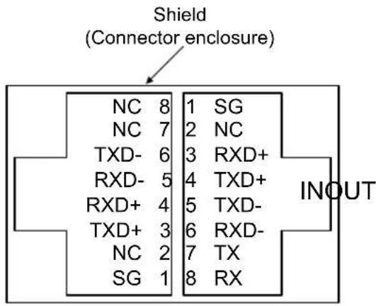
Fig.7-1: J4 rear panel IN/OUT connectors pinout
NOTE:
Tx and Rx are used for RS232 communication. Txd +/- and Rxd +/- are used for RS485 communication. Refer to RS232 and RS485 cable descriptions for connection details.
7.4 Connectig Power Supply To RS232 Or RS485 BUS
Connect rear panel IN connector to the controller RS232 or RS485 port using a suitable shielded cable. Refer to Figures 7-2, 7-3 and 7-4 for available RS232 and RS485 cables.
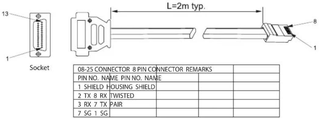
| 08-25 CONNECTOR 8 PIN CONNECTOR REMARKS | ||||
| PIN NO. NAME PIN NO. NAME | ||||
| 1 SHIELD HOUSING SHIELD | ||||
| 2 TX 8 RX | TWISTED | |||
| 3 RX 7 TX | PAIR | |||
| 7 SG 1 SG | ||||
Fig.7-2: RS232 cable with DB25 connector (P/N: Z/232-25)
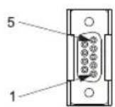
Socket
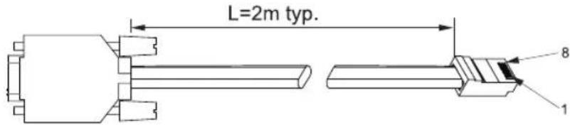
| D08-9 CONNECTOR 8 PIN CONNECTOR REMARKS | ||||
| PIN NO. NAME PIN NO. NAME | ||||
| HOUSING | SHIELD | HOUSING | SHIELD | |
| 2 | RX | 7 | TX TWISTED | |
| 3 | TX 8 | RX PAIR | ||
| 5 | SG | 1 SG | ||
Fig.7-3: RS232 cable with DB9 connector (P/N: Z/232-9)
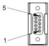
Socket
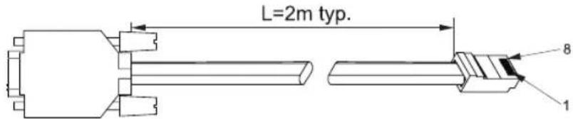
| D08-9 CONNECTOR | 8 PIN CONNECTOR REMARKS | ||
| PIN NO. NAME | PIN NO. | NAME | |
| HOUSING SH | ELD HOUSING SH | ELD | |
| 9 TXD- | 6 | RXD- | TWISTED |
| 8 TXD+ | 3 | RXD+ | PAIR |
| 1 SG | 1 | SG | |
| 5 RXD- | 5 | TXD- | TWISTED |
| 4 RXD+ 4 | TXD+ | PAIR | |
Fig.7-4: RS485 cable with DB9 connector (P/N: Z/485-9)
7.5 Rear Panel USB Connector
A standard USB Series B device connector is located on Rear panel for USB control. Refer to Fig.7-5 and Table 7-2.
1
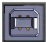
2
3
4
Pin Designator Description
| 1 VBUS +5 VDC |
| 2 D- Data - |
| 3 D+ Data + |
| 4 GND Interface com |
Fig.7-5: USB Connector
Table 7-2: USB connector pin out
7.5.1 USB Getting Started
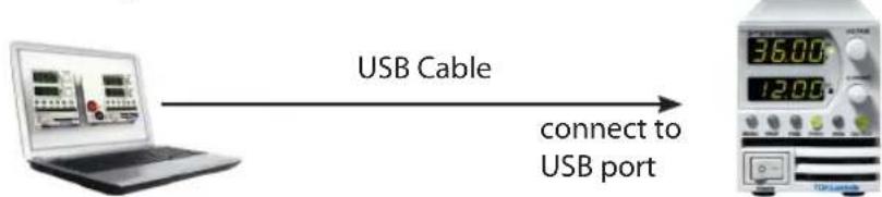
flowchart
graph LR
    A["Laptop with display"] -->|USB Cable| B["Digital terminal: 36.00, 12.00"]
    B -->|connect to USB port| A
The following steps will help you quickly get started connecting your USB-enabled instrument to the Universal Serial Bus (USB):
- Verify AC switch is OFF.
- Connect Z ^+ to the USB port on the computer.
-
Turn AC switch ON.
-
Insert the software CD-ROM that is shipped with the product to your CD-ROM Drive.
The Z ^+ drivers selection menu will automatically appear. click on the ICON "USB drivers". Install the USB Driver.
7.6 Multi Power Supply Connection to RS232 Or RS485 or USB
A Daisy-chain configuration of up to 31 units can be connected to RS232, RS485 or USB. The first unit connects to the controller via RS232, RS485 or USB and other units are connected with a RS485 bus. The user must set all slave power supplies to a unique address. No two power supplies may have the same address.
- First unit connection: Select communication Interface. Refer to section 7.2.3.
- Other unit connections: The other units on the bus are connected via their RS485 interface. Refer to Figures 7-6 and 7-7 for typical connections.
- Using the Linking cable supplied with each unit (Refer to Fig.7-8), connect each unit OUT connector to the next unit IN connector.

flowchart
graph TD
    A["In Power Supply #1"] --> B["RS232/485"]
    C["Power Supply #2"] --> D["RS485"]
    E["Power Supply #3"] --> F["RS485"]
    G["Power Supply #31"] --> H["RS485"]
    B --> I["IN POWER SUPPLY #1"]
    D --> J["IN POWER SUPPLY #2"]
    F --> K["IN POWER SUPPLY #3"]
Fig.7-6: Multi power supplies RS232/485 connection

flowchart
graph TD
    A["USB"] --> B["IN IN POWER SUPPLY #1"]
    B --> C["RS485"]
    C --> D["IN POWER SUPPLY #2"]
    D --> E["RS485"]
    E --> F["IN POWER SUPPLY #3"]
    F --> G["RS485"]
    G --> H["IN POWER SUPPLY #31"]
Fig.7-7: Multi power supplies USB connection
NOTES:
It is recommended when using ten or more power supplies in Daisy-chain system to connect 120Ω resistive termination at the last unit's RS-485 out connector 120Ω, 0.5W between TXD+ and TXD-. 120Ω, 0.5W between RXD+ and RXD-.

| 8 PIN CONNECTOR (IN) 8 PIN CONNECTOR (OUT) | |||
| PIN NO. NAME PIN NO. NAME | |||
| HOUSING SHIELD HOUSING | SHIELD | ||
| 1 SG 1 SG | |||
| 6 TXD- | 6 RXD- | ||
| 3 TXD+ | 3 RXD+ | ||
| 5 RXD- | 5 TXD- | ||
| 4 RXD+ | 4 TXD+ | ||
Fig.7-8: Serial link cable with RJ-45 shielded connectors (P/N: Z/RJ45)
7.7 GEN Protocol (GEN series communication language)
NOTE:
The address (ADR n) command must return an "OK" response before any other commands are accepted.
7.7.1 Data Format
Serial data format is 8 bit, one start bit and one stop bit. No parity bit.
7.7.2 End of Message
The end of message is the Carriage Return character (ASCII 13, 0x0D). The power supply ignores the Line Feed (ASCII 10, 0x0A) character.
7.7.3 Command Repeat
The backslash character "\" will cause the last command to be repeated.
7.7.4 Checksum
The user may optionally add a checksum to the end of the command. The checksum is "\" followed by two hex characters. If a command or a query has checksum, the response will also have one. There is no CR between the command string and the "\" sign. Example: STT? 3A STAT? 7B
7.7.5 Acknowledge
The power supply acknowledges received commands by returning "OK" message. If an error is detected, the power supply will return an error message. The rules for checksum also apply to the acknowledge feature.
7.7.6 Backspace
The backspace character (ASCII 8) clears the last character sent to the power supply.
7.7.7 Error Messages
The power supply will return error messages for illegal commands and illegal programming parameters. Refer to Table 7-3 for programming error messages and Table 7-4 for command error messages.
Error Code Description
E01 Returned when program voltage (PV) is programmed above acceptable range. Example: PV above 95% of OVP setting.
E02 Returned when programming output voltage below UVL setting.
E04 Returned when OVP is programmed below acceptable range. Example: OVP value is less than 105% of voltage setting.
E06 Returned when UVL value is programmed above the programmed output voltage.
E07 Returned when programming the Output to ON during a latched fault shut down.
E08 Cannot execute command via Advanced Slave Parallel mode.
Table 7-3: Programming error messages
Error Code Description
| C01 Illegal command or query |
| C02 Missing parameter |
| C03 Illegal parameter |
| C04 Checksum error |
| C05 Setting out of range |
Table 7-4: Commands error messages
7.8 GEN Command Set Description
7.8.1 General guides
- Any command or argument may be in capital letters or small letters.
- In commands with an argument, a space must appear between the command and the argument.
- For any command that sets a numeric value, the value may be up to 12 characters long.
- Carriage Return: If the CR character (ASCII 13) is received by itself, the power supply will respond with "OK" and CR.
7.8.2 Command Set Categories
The command set is divided into four categories as follows:
- Identification Commands
- Initialization Commands
- Output Commands
- Global Commands
- Auxiliary Commands
- Status Commands
7.8.3 Identification Commands
| IDN? | Returns the power supply model identification as an ASCII string:Default: "TDK-Lambda,ZX-Y" (one comma, no spaces)X = rated output voltageY = rated output current |
| REV? Returns the software version as an ASCII string. Current rev: "REV:1.0" | |
| SN? Return power supply serial number. Up to 12 characters in any format. | |
| DATE? Returns date of last calibration. Format "yyyy/mm/dd". Example "2009/12/17" | |
7.8.4 Initialization Commands
| Command Description | |
| ADR n ADR is followed by | address which can be 1 to 31 and is used to access the power supply. |
| CLS Clear status. Sets FEVE | and SEVE registers to zero. |
| RST | Reset command. Brings the power supply to a safe and known state:Output voltage: zero, Remote: non-latched remote,Output current: zero, Auto-start: Off,Output: Off, OVP: maximum,FOLD: Off, UVL: zeroThe conditional registers (FLT and STAT) are updated, the other registers are not changed. |
| RMT | Sets the power supply to local or remote mode:1. RMT 0 or RMT LOC, sets the power supply to Local mode.2. RMT 1 or RMT REM, sets the unit to remote mode.3. RMT 2 or RMT LLO, sets the unit to Local Lockout mode (latched remote mode). |
| RMT? | Returns the Remote mode setting:1. "LOC"- The unit is in Local mode.2. "REM"- The unit is in Remote mode.3. "LLO"- The unit is in Local Lockout (latched remote) mode. |
| \ Repeat last command. If | is received, the power supply will repeat the last command. |
7.8.5 Output Commands
| Command Description | |
| PV n | Sets the output voltage value in Volts. The range of voltage value is described in Table 7-5. The maximum number of characters is 12. See the following examples for PV n format: PV 12, PV 012, PV 12.0, PV 012.00, etc... |
| PV? | Reads the output voltage setting. Returns the string "n" where "n" is the exact string sent in the PV n command. When in Local mode, returns the PREVIEW (front panel) settings in a 5 digit string. |
| MV? | Reads the actual output voltage. Return 5 digit string.Example: 60V supply sends 01.150, 15.012, 50.000, etc... |
| PC n(See Note 1) | Sets the output current value in Amperes. The range of current values are described in Tables 7-6, 7-7 and 7-8. The maximum number of characters is 12. See the following examples for PC n format: PC 10, PC 10.0, PC 010.00, etc... |
| PC? | Reads the output current setting. Returns the string "n" where "n" is the exact string sent in the PC n command. When in Local mode, returns the PREVIEW (front panel) settings in a 5 digit string. |
| MC?(See Note 2) | Reads the actual output current. Returns 5 digit string.Example: 200A supply sends 000.50, 110.12, 200.00, etc... |
| DVC? | Display Voltage and Current data. Data will be returned as a string of ASCII characters.A comma will separate the different fields.The fields, in order, are: Measured Voltage, Programmed Voltage, Measured Current, Programmed Current, Over Voltage Set point and Under Voltage Set Point.Example: 5.9999, 6.0000, 010.02, 010.00, 7.500, 0.000 |
| OUT n | Turns the output to ON or OFF. Recover from Safe-Start, OVP or FLD fault. OUT 1 (or OUT ON)-Turn On. |
| OUT? | Returns the output On/Off status string.ON- output on. OFF- output off. |
| FLD n | Sets the Foldback protection to ON or OFF.FLD 1 (or FOLD ON) - Arms the Foldback protection.FLD 0 (or FOLD OFF)- Cancels the Foldback protection.When the Foldback protection has been activated, OUT 1 command will release the protection and re-arm it, while FLD 0 will cancel the protection. |
| FLD? | Returns the Foldback protection status string:"ON"- Foldback is armed, "OFF"- Foldback is canceled. |
| FBD nn | Add (nn x 0.1) seconds to the Fold Back Delay. This delay is in addition to the standard delay.The range of nn is 0 to 255. The value is stored in eprom at AC power and recovered at AC power up. |
| FBD? Supply returns the value of the added Fold Back Delay. | |
| FBDRST Reset the added | Fold Back Delay to zero. |
| OVP n | Sets the OVP level. The OVP setting range is given in Table 7-9. The number of characters after OVP is up to 12. The minimum setting level is approx. 105% of the set output voltage, or the value in Table 7-9, whichever is higher. Attempting to program the OVP below this level will result in execution error response ("E04"). The OVP setting stays unchanged. |
| OVP? | Returns the setting "n" where "n" is the exact string in the user's "OVP n". When in Local mode returns the last setting from the front panel in a 4 digit string. |
| OVM Sets OVP level to the maximum level. Refer to Table 7-9. | |
| UV? Returns the under voltage mode UVP or UVL. | |
| UVL n | Sets Under Voltage Limit. Maximum value of "n" is 5% below PV setting, but returns "E06" if higher. Refer to Table 7-10 for UVL programming range. |
| UVL? | Returns the setting "n" where "n" is the exact string in the user's "UVL n". When in Local mode, returns the last setting from the front panel in a 4 digit string.When UVP is activated, returns the setting |
| UVP n | Sets Under Voltage Protection. Maximum value of "n" is 5% below PV setting, but returns "E06" if higher. Refer to Table 7-10 for UVP programming range. |
| UVP? | Returns the setting "n" where "n" is the exact string in the user's "UVP n". When in Local mode, returns the last setting from the front panel in a 4 digit string. |
| AST n | Sets the auto-restart mode to ON or OFF.AST 1 (or AST ON)- Auto restart on.AST 0 (or AST OFF)- Auto restart off. |
| AST? Returns the string auto-restart mode status. | |
| SAV n Saves present settings to specified location in memory (n=1...4). | |
| RCL n Recalls saved settings from specified location in memory (n=1...4). | |
| MODE? | Returns the power supply operation mode. When the power supply is On (OUT 1) it will return "CV" or "CC". When the power supply is OFF (OUT 0) it will return "OFF". |
| PMS n | Sets the Master/Slave parallel operation mode of the power supply. n=H1...H6 (Master), n=SL (Basic Mode Slave), n=ADSL (Advanced Mode Slave). (Refer to tables 5-2, 5-2.1). |
| PMS? | Returns the Master/Slave setting. Master: H1...H6, Slave (Basic mode): S, Slave (Advanced mode): AD |
NOTES:
- In Advanced Parallel mode (Refer to Sec. 5.5.3), "n" is the total system current.
- In Advanced Parallel mode, "MC?" returns the Master unit current multiplied by the number of Slave units.
- UVL? will return "C01" if UVP is activated and vice versa.
- No command execution in Advance slave mode.
7.8.6 Global Output Commands
General
Global commands can be received by all power supplies connected to the BUS, without individual address commands. All power supplies will execute the command immediately. There is no acknowledgment back to the PC when using global commands. A delay must be set of 20msec after each global command. Error messages are not reported back to the issuing PC.
| GRST | Reset. Brings the Power Supply to a safe and known state:Output voltage: 0V, output current: 0A, OUT: Off, Remote: RMT 1, AST: Off, OVP:Max, UVL:0V.The conditional register (FLT and STAT) are updated. Other registers are not changed.Non-Latching faults (FoldBack, OVP, SO, UVP) are cleared, OUT fault stays. |
| GPV n | Sets the output voltage value in volts. The range of voltage values is shown in Table 7-5. 'n' may be up to 12 char plus dec. pt |
| GPC n | Program the output current value in amperes. The range of current values is shown in Tables 7-6, 7-7 and 7-8. 'n' may be up to 12 char plus dec. pt |
| GOUT | Turns the output to ON or OFF:"OUT 1/ON" = turn on"OUT 0/OFF" = turn off, clears CV and CC bits in the Status Condition (STAT).OUT ON will respond with "E07" if the output cannot be turned on because of a latching fault (OTP, AC, ENA, SO) shutdown. |
| GSAV n | Saves present settings to specified loction in memory (n=1...4). Same settings as power-down last settings listed in table 5-7. |
| GRCL n Recall | I saved settings from specified location in memory (n=1...4). |
| Model Rated Output Voltage (V) | Minimum (V) Maximum (V) |
| 10 00.00 10.00 | |
| 20 00.00 20.00 | |
| 36 00.00 36.00 | |
| 60 00.00 60.00 | |
| 100 000.0 100.0 |
Table 7-5: Voltage programming range
NOTE:
The power supply can accept values higher by 5% than the table values, however it is not recommended to program the power supply over the rated values.
| Model Minimum (A) Maximum (A) | ||
| 10-20 00.00 | 20.00 | |
| 20-10 00.00 | 10.00 | |
| 36-6 0.000 | 6.000 | |
| 60-3.5 | 0.000 | 3.500 |
| 100-2 0.000 | 2.000 | |
Table 7-6: Z200 models Current programming range
| Model Minimum (A) Maximum (A) | ||
| 10-40 00.00 | 40.00 | |
| 20-20 00.00 | 20.00 | |
| 36-12 00.00 | 12.00 | |
| 60-7 0.000 | 7.000 | |
| 100-4 0.000 | 4.000 | |
Table 7-7: Z400 models Current programming range
| Model Minimum (A) Maximum (A) | |
| 10-72 00.00 72.00 | |
| 20-40 00.00 40.00 | |
| 36-24 00.00 24.00 | |
| 60-14 00.00 14.00 | |
| 100-8 00.00 8.000 | |
Table 7-8: Z800 models Current programming range
NOTE:
The power supply can accept values higher by 5% than the table values, however it is not recommended to program the power supply over the rated values.
| Model Rated Output Voltage (V) | Minimum (V) | Maximum (V) |
| 10 0.5 12.0 | ||
| 20 1.0 24.0 | ||
| 36 2.0 40.0 | ||
| 60 5.0 66.0 | ||
| 100 5.0 110 |
Table 7-9: OVP programming range
| Model Rated Output Voltage (V) | Minimum (V) | Maximum (V) |
| 10 0 9.5 | ||
| 20 0 19.0 | ||
| 36 0 34.2 | ||
| 60 0 57.0 | ||
| 100 0 95.0 |
Table 7-10: UVL/UVP programming range
NOTE:
The UVP protection starts operating for values higher than 5% of Rated Output Voltage.
7.8.7 Auxiliary Commands
| SOP Sets SO | polarity "SO 1/ON"-Positive (default), "SO 0/OFF"-Negative |
| SOP? Returns the SO polarity | |
| RIE Remote | Interlock (Inhibit) enable. "RIE 1/ON"-Enable, "RIE 0/OFF"-Disable" |
| RIE? Returns | Interlock enable status. "ON"-interlock enable, "OFF"-interlock disable. |
| FRST | Factory reset command. This command cover *RST command and additional settings. Sets factory default. This command breaks communication. Refer to Table5-7. |
| MP? Reads the actual output power. Returns 5 digit string. | |
| REL1 Set auxiliary programmed pin state J3-1. "REL1 1/ON"- High, REL1 0/OFF"- Low | |
| REL1? | Response auxiliary programmed pin state J3-1. |
| REL2 | Set auxiliary programmed pin state J3-6, "REL2 1/ON"- High, REL2 0/OFF"- Low |
| REL2? | Response auxiliary programmed pin state J3-6 |
7.8.8 Status Commands
Refer to section 9.3.1, 9.3.2 for Register definitions.
| # Command Description | |
| 1 STT? | |
| 2 FLT? Reads Fault Conditional Register. Return 4-digit hex. | |
| 3 FENA Set Fault Enable Register using 4-digit hex. | |
| 4 FENA? Reads Fault Enable Register. Returns 4-digit hex. | |
| 5 FEVE? Reads Fault Event Register. Returns 4-digit hex. Clears bits of Fault Event Register. | |
| 6 STAT? Reads Status Conditional Register. Returns 4-digit hex. | |
| 7 SENA Sets Status Enable Register using 4-digit hex. | |
| 8 SENA? Reads Status Enable Register. Returns 4-digit hex. | |
| 9 SEVE? Reads Status Event register. Returns 4-digit hex. Clears bits of Status Event register. | |
7.9 Serial Communication Test Set-Up
Basic set-up to test serial communication operation.
-
Equipment: PC with Windows Hyper Terminal, private edition, software installed, Z RS232 cable.
-
PC set-up: 2.1 Open Hyper Terminal.....New Connection.
2.2 Enter a name
2.3 Connect to....Direct to Com1 or Com 2
2.4 Configure port properties:
Bits per second .....9600
Data bits .....8
Parity ....None
Stop bits.....1
Flow control......None
2.5 Open Properties in the program File....Properties
2.6 Setting: ASCII Set Up
Select Echo characters locally, select send line ends with line feed.
On some PC systems, pressing the number keypad "Enter" will
distort displayed messages. Use the alphabetic "Enter" instead.
- Power supply set-up:
3.1 Connect the power supply to the PC using the RS232 cable.
3.2 Set via the front panel: Baud Rate: 9600, Address: 06, RS232, GEN Language
- Communication test:
4.1 Model identification:
PC: write: ADR 06
Power supply response: "OK"
4.2 Command test:
PC write: OUT 1
Power supply response: "OK"
PC write: PV n (for n values see Table 7-5)
Power supply response: "OK"
PC write: PC n (for n values see Tables 7-6, 7-7 and 7-8)
Power supply response: "OK"
The power supply should turn on and the display will indicate the output voltage and the actual output current.
7.10 SCPI Protocol
NOTE:
Selecting the power supply (INSTrument:NSELect
) is necessary before using any other command.7.10.1 Data Format
Serial data format is 8 bit, one start bit and one stop bit. No parity bit.
7.10.2 End of Message
End of message is the Carriage Return character (ASCII 13) and the Line Feed (ASCII 10) character.
7.10.3 End of Command
End of command is Carriage Return character (ASCII 13) and/or the Line Feed (ASCII 10) character.
7.10.4 Checksum
The user may optionally add a checksum to the end of the command. The checksum is "\" followed by two hex characters. If a command or a query has checksum, the response will also have one. There is no CR between the command string and the "\" sign.
7.10.5 SCPI Requirements
The power supply conforms to the following SCPI requirements:
- SCPI common commands.
- SCPI Command Tree.
3 Subsystem commands. - The ROOT level.
- The power supply is powered On
- A device clear (DCL) is sent to the power supply
- The SCPI interface encounters a root specifier (:)
- Questionable Status Register (QSR), Condition, Event, Enable
- Operation Status Register (OSR), Condition, Event, Enable
- Status Byte Register (SBR)
- Standard Event Status Register (SESR)
- Using the MIN and MAX Parameters.
- Suffix and Multipliers.
- Boolean data. 1 | 0 or ON | OFF
7.10.6 SCPI Command Hierarchy
SCPI is an ASCII-based command language designed for use in test and measurement equipment. The command structure is organized around common roots, or nodes, which are the building blocks of SCPI subsystems. An example of a common root is OUTPUT, and some of the commands that reside in the OUTPUT subsystem are:
OUTPUT
[:STATE]<bool>
:PON
    [:STATE]<bool>
:PROTection
    :CLEar
    :FOLDback
    [:MODE]
A colon (:) is used to separate a command keyword from a lower-level keyword.
7.10.7 Header
Headers are instructions recognized by the power supply. Headers (which are sometimes known as "keywords") may be either in long or short form.
Long form The header is completely spelled out, such as VOLTAGE, STATUS, and DELAY Short form The header has only the first three or four letters, such as VOLT, STAT, and DEL.
The SCPI interface is not sensitive to case. It will recognize any case mixture, such as TRIGGER, Trigger, TRIGger. Short form headers result in faster program execution.
7.10.8 Data Formats
| Data Formats Description | |
| Digits with an implied decimal point assumed at the right of the least-significant digit. Examples: 256 | |
| Digits with an explicit decimal point. Example: .0253 | |
| Digits with an explicit decimal point and an exponent. Example: 2.73E+2 | |
| Extended format that includes, and. Examples: 273 273.1 2.73E2 | |
| Expanded decimal format that includesand MIN MAX. Examples: 273,273.1, 2.73E2, MAX. MIN and MAX are the minimum and maximum limit values that are implicit in the range specification for the parameter. | |
| Boolean Data. Example: 0 | 1 or ON | OFF | |
7.10.9 Character Data
7.10.10 Commands Notes
• Expressions enclosed in square brackets, [ ], are optional and entered without the [ or ].
- Expressions enclosed in greater than/less than, < >, are programming values and entered without the < or >.
• The expression
• In all commands upper case characters can be interchanged with lower case characters.
7.11 SCPI Common Commands
Common commands begin with an * and consist of three letters (command) or three letters and a ? (query). Common commands are defined by the IEEE 488.2 standard to perform some common interface functions.
\*CLS
Clear Status command. Clears the entire status structure.
NOTE:
Execution time for this command 150mS
| Meaning and Type Clear Status | |
| Command Syntax *CLS | |
| Parameters None | |
| Query Syntax None |
\*ESE
Standard Event Status Enable command. Modifies the contents of the Event Status Enable Register.
| Meaning and Type Event Status Enable | Device Status | |
| Command Syntax *ESE | ||
| Parameters 0 to 255 | ||
| Query Syntax *ESE? | ||
| Returned Parameters3digits | ||
Bit Position 76543210
| Bit Name PON 0 CME EXE DDE QYE 0 OPC | ||||||||
| Bit Weight | 128 | 64 | 32 | 16 | 8 | 4 | 2 | 1 |
CME = Command error; DDE = Device-dependent error; EXE = Execution error; OPC = Operation, complete; PON Power-on; QYE = Query error
\*ESR?
Standard Event Status Register query. Returns the contents of the Event Status Register.
| Meaning and Type | Event Status | Device Status |
| Query Syntax | *ESR? | |
| Returned Parameters | 0 to 255 (Register Decimal value) | |
\*IDN?
Identification query. Returns an identification string in the following format: 'Manufacturer, Model, Serial number, Firmware level'.
| Meaning and Type | Identification System Interface | |
| Query Syntax | *IDN? | |
| Returned Parameters | Field | Information |
| TDK-Lambda | Manufacturer | |
| Z | Model | |
| -- | Model ratings | |
| 25B1234 | Serial number, typically 7 alpha-numeric characters | |
| 3.0-C1 | Revisions,-- | |
| Example | TDK-Lambda,Z20-30,25B1234, 1.0-C1 | |
\*OPC
Operation Complete command. Sets the Operation Complete bit in the Standard Event Status Register if all commands and queries are completed.
| Meaning and Type Operation | Complete Device Status | |
| Command Syntax *OPC | ||
| Parameters None | ||
\*OPC?
Operation Complete query. Returns ASCII '1' as soon as all commands and queries are completed.
| Meaning and Type Operation | Complete Device Status | |
| Query Syntax *OPC? | ||
| Parameters | ASCII 1 is placed in the Output Queue when the power supply has completed operations. | |
\*OPT?
The options (OPT) query returns a comma-separated list of all of the instrument options currently installed on the signal generator.
| Parameter Option | |
| 0 NONE | |
| 1 IEEE | |
| 2 LAN | |
| 3 BOTH |
Query Syntax *OPT?
Returned Parameters
\*PSC
The Power-On Status Clear (PSC) command controls the automatic power-on clearing of the Service Request Enable Register, the Standard Event Status Enable Register, and device-specific event enable registers.
• ON(1) - This choice enables the power-on clearing of the listed registers.
- OFF(0) - This choice disables the clearing of the listed registers and they retain their status when a power-on condition occurs.
| Meaning and Type | Power-on Status Clear Device Initialization |
| Command Syntax | *PSC |
| Parameters | 0 | 1 | OFF | ON |
| Example | *PSC 0 *PSC 1 |
| Query Syntax | *PSC? |
| Returned Parameters | <NR1> 0 | 1 |
\*RCL n
Restores the power supply to a state previously stored in memory by *SAV command. Refer to Table 5-7.
| Command Syntax *RCL | |
| Parameters 1 to 4 | |
| Example *RCL 3 |
\*RST
This command resets the power supply to a defined state as shown in Table 5-7. *RST also forces an ABORt command.
| Command Syntax *RST | |
| Parameters None |
\*SAV n
The SAV command saves all applied configuration setting. Refer to Table 5-7.
| Command Syntax *SAV | |
| Parameters 1 to 4 | |
| Query Syntax None |
\*SRE
Service Request Enable command. Modifies the contents of the Service Request Enable Register.
| Meaning and Type Service Request | Enable Device Interface |
| Command Syntax *SRE | |
| Parameters 0 to 255 | |
| Default Value See *PSC | |
| Example *SRE 20 | |
| Query Syntax *SRE? | |
| Returned Parameters(Register binary value) 3digits | |
\*STB?
Status Byte query. Returns the contents of the Status Byte Register.
| Meaning and Type Status Byte Device Status | |
| Query Syntax *STB? | |
| Returned Parameters(Register binary value) |
| Bit Position 7 6 5 4 3 2 1 0 | ||||||||
| Condition OPER MSS ESB | MAV QUES 0 0 (RQS) | 0 | ||||||
| Bit Weight | 128 | 64 | 32 | 16 | 8 | 4 | 2 | 1 |
| ESB = Event status byte summary; MAV = Message available | ||||||||
| MSS = Master status summary; OPER = Operation status summary; | ||||||||
| QUES = Questionable status summary; RQS = Request for service | ||||||||
Table 7-11: Bit Configuration of Status Byte Register
\*TRG
The Trigger command starts the waveform when the trigger source is set to BUS.
| Meaning and Type | Trigger | Device Trigger |
| Command Syntax | *TRG | |
| Parameters | None | |
| Query Syntax None | ||
ABORt
Resets the trigger system and places the power supply in an IDLE state without waiting for the completion of the trigger cycle.
| Command Syntax | ABORt |
| Parameters | None |
| Example | ABOR |
| Query Syntax None |
7.12 SCPI Subsystem Commands
Subsystem commands are specific to power supply functions. They can be a single command or a group of commands. Groups are comprised of commands that extend one or more levels below the root.
Commands followed by a question mark (?) take only the query form. Except as noted in the syntax descriptions, all other commands take both the command and query form.
7.12.1 Output Subsystem
OUTPUT
This command enables or disables the power supply output. When output is turned off, voltage display shows "OFF".
| SCPI Command Syntax OUTPUT[:STATE] | |
| GEN Command Syntax OUT | |
| Parameters 0|OFF 1|ON | |
| *RST Value OFF | |
| Examples OUTP 1 OUTP:STAT ON | |
| Query Syntax OUTPUT[:STATE]? | |
| Returned Parameters 0|1 |
OUTPUT:PON[:STATE]
- AUTO - The power supply output will return to its previous value when the latching fault condition is removed or to the stored value after AC recycle.
- SAFE - The power supply output will remain Off after the fault condition is removed or after AC recycle.
| SCPI Command Syntax OUTPUT:PON[:STATe] | |
| GEN Command Syntax AST | |
| Parameters 0|OFF 1|ON | |
| *RST Value OFF | |
| Examples OUTPUT:PON 1 | |
| Query Syntax OUTPUT:PON[:STATe]? | |
| Returned Parameters 0|1 |
OUTPUT:PROTection:CLEar
This command clears the latch that disables the output when an over voltage (OVP), under voltage (UVP), or foldback (FOLD) fault condition is detected. All conditions that generate a fault must be removed before the latch can be cleared. The output is then restored to the state before the fault condition occurred.
| SCPI Command Syntax OUTPUT:PROTction:CLEar |
| GEN Command Syntax None |
| Parameters None |
OUTPUT:PROTection:FOLDBack
Foldback mode is used to disable the output when a transition is made between the operation modes. The power supply will turn off the output after a specified delay if the power supply makes transition into CV mode or into CC mode. This feature is particularly useful for protecting current or voltage sensitive loads.
| SCPI Command Syntax OUTPUT:PROT:FOLDback[:MODE] | |
| GEN Command Syntax FLD | |
| Parameters OFF|0, CC|1, CV|2. | |
| *RST Value OFF | |
| Examples OUTPUT:PROT:FOLDback[:MODE] CC | |
| Query Syntax OUTPUT:PROT:FOLDback[:MODE]? | |
| Returned Parameters |
OUTPUT:PROTection:DELay
Sets the delay time between the programming of an output change that produces a CV or CC status condition. This command applies to UVP and Foldback functions.
| SCPI Command Syntax OUTPUT:PROTction:DELay | |
| GEN Command Syntax FBD | |
| Parameters 0.1 to 25.5|MIN|MAX (step 0.1s) | |
| Unit S (second) | |
| *RST Value 0mS | |
| Examples OUTPUT:PROTection:DELay 2E-1 | |
| Query Syntax OUTPUT:PROTection:DELay? | |
| Returned Parameters |
OUTPUT:ILC:MODE
Selects the mode of operation of the Remote Inhibit protection. In OFF mode the power supply ignores J3-4 (ILC) status.
| SCPI Command Syntax OUTPUT:ILC:MODE | |
| GEN Command Syntax RIE | |
| Parameters 0|OFF 1|ON | |
| *RST Value OFF | |
| Examples OUTPUT:ILC:MODE ON | |
| Query Syntax OUTPUT:ILC:MODE? | |
| Returned Parameters ON/OFF |
OUTPUT:TTLTrg:MODE
Sets the operation of the Trigger Out signal to either OFF, Function Strobe or Trigger mode. Programming Mode NONE, FIX:
• In TRIG mode, trigger is generated when output status changes.
- In Function Strobe mode, an output pulse is generated automatically any time an output parameter such as output, voltage or current is programmed.
Programming modes LIST or WAVE:
• In TRIG mode, trigger is generated when LIST or WAVE is completed.
- In Function Strobe mode, an output pulse is generated automatically any time a step is completed. The power supply Trigger Out signal is available at J3-3 connector on the rear panel.
| SCPI Command Syntax OUTPUT:TTLTrg:MODE | |
| GEN Command Syntax None | |
| Parameters TRIG| FSTR|OFF | |
| *RST Value OFF | |
| Examples OUTP:TTLT:MODE TRIG | |
| Query Syntax OUTP:TTLT:MODE? | |
| Returned Parameters |
OUTPUT:RELay1(2):STATE
Sets pin J3-1 (1) and J3-6 (2) state. The ON parameter is according to low level.
| SCPI Command Syntax OUTPUT:RELay1(2)[:STATe] | |
| GEN Command Syntax REL1(2) | |
| Parameters 0|OFF 1|ON | |
| *RST Value 1 | |
| Examples OUTP:REL1(2) 1 OUTP:REL1(2) ON | |
| Query Syntax OUTPUT:REL1(2)[:STATe]? | |
| Returned Parameters 0|1 |
OUTPUT:MODE?
Returns the power supply operation mode. When the power supply is On (OUT 1) it will return "CV" or "CC". When the power supply is OFF (OUT 0) it will return "OFF".
| SCPI Query Syntax OUTPUT:MODE? | |
| GEN Query Syntax MODE? | |
| Returned ParametersCV|CC|OFF | |
7.12.2 Instrument Subsystem
The subsystem programs one or more power supplies.
INSTrument:COUPle
| SCPI Command Syntax INSTrument | COUPIe |
| GEN Command Syntax None | |
| Parameters ALL|NONE |
INSTrument:NSELect
| SCPI Command Syntax INSTrument: | NSELect |
| GEN Command Syntax ADR n (single address) | |
| Examples INSTrument:NSELect 6 | |
| Query Syntax INSTrument:NSELect? | |
7.12.3 Voltage Subsystem
VOLTage
Sets the output voltage value in Volts. The range of voltage values are described in Table 7-5. The maximum number of characters is 12.
| SCPI Command Syntax [SOURce]:VOLTage[:LEVel] [:IMMediate][:AMPLitude] | |
| GEN Command Syntax PV < NRf+> | PV? |
| Default Suffix V | |
| *RST Value 0 | |
| Examples :VOLT 500 MV VOLT:LEV | 234.56789 |
| Query Syntax | [SOURce]:VOLTage[:LEVel][:IMMediate][:AMPLitude]?VOLTage? MAX VOLTage? MIN |
| Returned Parameters | VOLT? returns the present programmed voltage level.VOLT? MAX and VOLT? MIN returns the maximum and minimum programmable voltage levels. |
VOLTage:MODE
This command selects FIX, LIST, WAVE subsystems control over the power supply output voltage.
| SCPI Command Syntax [SOURce]:VOLTage:MODE |
| GEN Command Syntax None |
| Parameters NONE | FIXed | LIST | WAVE |
| *RST Value NONE |
| Examples VOLT:MODE LIST VOLT:MODE FIX |
| Query Syntax [SOURce]:VOLTage:MODE? |
| Returned Parameters NONE | FIX | LIST | WAVE |
NOTE:
VOLT:MODE LIST and WAVE is an implied ABORT command. WAVE mode cannot be programmed simultaneously for both Voltage and Current. Only the last sent command can be accepted as WAVE. Previous mode reverts to NONE.
VOLTage:PROTction:LEVel
Sets the OVP level. The OVP setting range is given in Table 7-9. The number of characters after OVP is up to 12. The minimum setting level is approx. 105% of the set output voltage, or the value in Table 7-9, whichever is higher.
| SCPI Command Syntax [SOURce]:VOLTage:PROTection:LEVel | |
| GEN Command Syntax OVP < NRf+> | |
| Default Suffix V | |
| *RST Value MAX | |
| Examples VOLT:PROT:LEV 2.5 | |
| Query Syntax | [SOURce]:VOLTage:PROT:LEV?VOLT:PROT:LEVel? MIN VOLT:PROT:LEVel? MAX |
| Returned Parameters | VOLT:PROT:LEV? returns presently programmed OVP level. VOLT:PROT:LEV? MAX and VOLT:PROT:LEV? MIN return the maximum and minimum programmable OVP levels. |
NOTE:
VOLT:PROT:LEV MIN set OVP level 5% above voltage set value
VOLTage:PROTction:LOW:STATE
Sets the under voltage protection (UVP) status of the power supply. If the UVP status selected, then the under voltage protection is enabled.
| SCPI Command Syntax [SOURce]:VOLTage:PROTection:LOW:STATe | |
| GEN Command Syntax UVL < NRf+>, UVP < NRf+> | |
| Parameters UVL|UVP | |
| *RST Value UVL | |
| Examples VOLT:PROT:LOW:STAT UVP | |
| Query Syntax [SOURce]:VOLTage:PROTection:LOW :STATe? | |
| Returned Parameters UVP|UVL | |
VOLTage:PROTction:LOW
Sets the under voltage protection (UVP) level of the power supply.
| SCPI Command Syntax [SOURce]:VOLTage:PROTection:LOW | |
| GEN Command Syntax UVL < NRf+> , UVP < NRf+> | |
| Default Suffix V | |
| *RST Value 0 | |
| Examples VOLT:PROT:LOW 2.5 VOLT:PROT:LOW MAX | |
| Query Syntax | [SOURce]:VOLTage:PROTection:LOW [:LEVel]?VOLT:PROT:LOW? MIN; VOLT:PROT:LOW? MAX |
| Returned Parameters | VOLT:PROT:LOW? returns presently programmed UVP level.VOLT:PROT:LOW? MAX and VOLT:PROT:LOW? MIN returns the maximum and minimum programmable UVP levels. |
NOTE:
VOLT:PROT:LOW MAX set UVP level maximum 5% below voltage value
VOLTage:TRIGger
Programs the pending triggered voltage level of the power supply. The pending triggered voltage level is a stored value that is transferred to the output terminals when a trigger occurs.
| SCPI Command Syntax [SOURce]:VOLTage[:LEVel]:TRIGger [:AMPLitude] | |
| GEN Command Syntax None | |
| Default Suffix V | |
| Examples VOLT:TRIG 1200 MV VOLT:LEV:TRIG 1.2 | |
| Query Syntax [SOURce]:VOLTage[:LEVel]:TRIGger [:AMPLitude]? | |
| Returned Parameters | VOLT:TRIG? returns the presently programmed voltage level.If the VOLT:TRIG level is not programmed, the default value is 0V. |
7.12.4 Current Subsystem
This subsystem programs the output current of the power supply.
CURRENT
Sets the output current value in Amperes. The range of current values are described in Tables 7-6, 7-7 and 7-8. The maximum number of characters is 12.
| SCPI Command Syntax [SOURce]:CURRent[:LEVel] [:IMMediate][:AMPLitude]<NRf+> | |
| GEN Command Syntax PC<NRf+>PC? | |
| Default Suffix A | |
| *RST Value 0 | |
| Examples CURR 500 MA CURR:LEV .5 | |
| Query Syntax | [SOURce]:CURRent[:LEVel][:IMMediate][:AMPLitude]?[SOURce]:CURRent? MAX [SOURce]:CURRent? MIN |
| Returned Parameters | <NR3> CURR? returns the present programmed current level.CURR? MAX and CURR? MIN returns the maximum and minimum programmable current levels. |
CURRENT:MODE
This command selects FIX, LIST, WAVE subsystems control over the power supply output current.
| SCPI Command Syntax [SOURce]:CURRent:MODE |
| GEN Command Syntax None |
| Parameters NONE | FIXed | LIST | WAVE |
| *RST Value NONE |
| Examples CURR:MODE LIST CURR:MODE FIX |
| Query Syntax [SOURce]:CURRENT:MODE? |
| Returned Parameters NONE | FIX | LIST | WAVE |
CURRent:TRIGger
Programs the pending triggered current level of the power supply. The pending triggered current level is a stored value that is transferred to the output terminals when a trigger occurs.
| SCPI Command Syntax [SOURce]:CURRent[:LEVel]:TRIGger[:AMPLitude] | |
| GEN Command Syntax None | |
| Default Suffix A | |
| Examples CURR:TRIG 3200 MA CURR:LEV:TRIG 3.2 | |
| Query Syntax [SOURce]:CURRent[LEVel]:TRIGger[:AMPLitude]? | |
| Returned Parameters | <NR3> CURR:TRIG? returns the presently programmed triggered level. If no triggered level is programmed, the CURR level is returned. |
NOTE:
CURR:MODE LIST and WAVE are an implied ABORt command. Only the last sent command can be accepted as WAVE or LIST. Previous mode reverts to NONE.
7.12.5 Measure Subsystem
This subsystem reads the actual voltage and current. The power is a result of multiplying voltage and current measurements.
MEASure: CURRENT?
Reads the measured output current. Returns a 5 digit string.
| SCPI Command Syntax MEASure:CU | RRent? |
| GEN Command Syntax MC? | |
| Parameters None | |
| Default Suffix A | |
| Returned Parameters |
MEASure:VOLTage?
Reads the measured output voltage. Returns a 5 digit string.
| SCPI Command Syntax MEASure:VOLTage? | |
| GEN Command Syntax MV? | |
| Parameters None | |
| Default Suffix V | |
| Returned Parameters | |
MEASure:POWer?
Reads the measured output power. Returns a 5 digit string.
| SCPI Command Syntax MEASure:PO | Wer? |
| GEN Command Syntax MP? | |
| Parameters None | |
| Default Suffix W | |
| Returned Parameters |
7.12.6 DISPLAY Subsystem
DISPLAY:STATE
Turns front panel voltage and Current display toggle On or Off.
| SCPI Command Syntax DISPLAY[:WINDow]:STATe | |
| GEN Command Syntax none | |
| Parameters 0|OFF 1|ON | |
| Examples DISP:STAT 1 DISP:STAT OFF | |
| Query Syntax DISPLAY[:WINDow]:STAT? | |
| Returned Parameters 0 |1 |
DISPLAY:FLASH
Makes front panel voltage and Current displays flash.
| SCPI Command Syntax DISPLAY[:WINDow]:FLASH |
| GEN Command Syntax none |
| Parameters 0|OFF 1|ON |
| Examples DISP:FLASH 1 DISP:FLASH OFF |
7.12.7 INITiate Subsystem
INITiate
Enables the trigger subsystem. If a trigger circuit is not enabled, all trigger commands are ignored.
| SCPI Command Syntax INITiate[:IMM | Mediate] |
| GEN Command Syntax None | |
| Parameters None | |
| Examples INIT:IMM | |
| Query Syntax None |
INITiate:CONTinuous
- INIT:CONT 0 - Enables the trigger subsystem only for a single trigger action. The subsystem must be enabled prior to each subsequent trigger action.
- INIT:CONT 1 - Trigger system is continuously enabled and INIT is redundant.
| SCPI Command Syntax INITiate:CONTinuous | |
| Parameters 0|OFF 1|ON | |
| Examples INIT:CONT 1 INIT:CONT ON | |
| Query Syntax INITiate:CONTinuous? | |
| Returned Parameters 0 |1 |
NOTE:
When power supply is in INIT:CONT ON mode, it's impossible to change any programming parameter. Display shows "Err". Send ABORt commands to allow parameter change.
7.12.8 LIST Subsystem
This subsystem receives parameters to create a step waveform of the output voltage or current.
NOTE:
All list subsystem commands (as well as CURR:MODE LIST and VOLT:MODE LIST) are implied ABORt commands.
LIST:COUNT
Sets the number of times that the list is executed before it is completed. The command accepts parameters in the range 1 through 9999, but any number greater than 9999 is interpreted as INFinity. Use INF if you wish to execute a list indefinitely.
| SCPI Command Syntax [SOURce]:LIST:COUNt | |
| Parameters 1 to 9999 | INFinity | |
| *RST 1 | |
| Examples LIST:COUN 3 LIST:COUN INF | |
| Query Syntax [SOURce]:LIST:COUNt? (if count>9999 the response is INF) | |
| Returned Parameters |
LIST:CURRent
Specifies the output current points in a list. The current points are given in the command parameters, which are separated by commas.
| SCPI Command Syntax [SOURce]:LIST:CURRENT{,} | |
| Default Suffix A | |
| Examples | LIST:CURR 2.5,3.0,3.5 LIST:CURR MAX,2.5,MIN up to 12 parameters |
| Query Syntax LIST:CURRENT? | |
| Returned Parameters 2.5,3.0,3.5 | |
LIST:LOAD
Loads from memory LIST type. Type voltage/current values, dwell values, STEP parameter and counter specified in stored numbers <1..4>
| SCPI Command Syntax [SOURce]LIST:LOAD | |
| Examples LIST:LOAD 3 |
LIST:DWELI
Specifies the time interval that each value (point) of a list is to remain in effect.
| SCPI Command Syntax [SOURce]:LIST:DWELI{,} | {,} |
| Range 0.01 to 129,600 seconds | |
| Default Suffix S | |
| Examples LIST:DWEL .6,1.5,1.5,.4 up | to 12 parameters |
| Related Commands | CURR:MODE LIST:COUN LIST:CURR LIST:STEPLIST:VOLT VOLT:MODE |
| Query Syntax LIST:DWEL? | |
| Returned Parameters .6,1.5,1.5,.4 |
LIST:STEP
Determines if a trigger causes a list to advance only to its next point or to sequence through all the points.
• LIST:STEP AUTO - When triggered, it creates waveforms consecutively, until the list is completed.
• LIST:STEP ONCE - When triggered, it executes one step from the list.
| SCPI Command Syntax [SOURce]:LIST:STEP |
| Parameters AUTO | ONCE |
| *RST AUTO |
| Examples LIST:STEP ONCE |
| Query Syntax [SOURce]:LIST:STEP? |
| Returned Parameters AUTO | ONCE |
LIST:VOLTage
Specifies the output voltage points in a list. The voltage points are given in the command parameters, which are separated by commas.
| SCPI Command Syntax [SOURce]:LIST:VOLTage{,} | |
| Default Suffix V | |
| Examples | LIST:VOLT 2.0,2.5,3.0 LIST:VOLT MAX,2.5,MIN up to 12 parameters |
| Query Syntax LIST:VOLT? | |
| Returned Parameters 2.0,2.5,3.0 | |
LIST:STORE
Saves data under specified numbers <1..4> of the last LIST typed (voltage or/and current, dwell time, STEP parameter and counter).
| SCPI Command Syntax [SOURce]LIST:STORe | |
| Example LIST:STORe 3 |
7.12.9 STATus Subsystem
Refer to Fig. 9-1 for more details.
STATus:OPERation:EVENT?
This query returns the value of the Event register. This is a read-only register that receives data from the Condition register according to Enable register setting. Reading the Event register clears it.
| SCPI Command Syntax STATus:OPER | Ration:EVENT? |
| GEN Command Syntax SEVE? | |
| Parameters None | |
| Returned Parameters(Register Value) decimal | |
| Examples STAT:OPER:EVENT? |
STATus:OPERation:CONDITION?
Returns the value of the Condition register, which is a read-only register that holds the real-time (unlatched) operational status of the power supply.
| SCPI Command Syntax STATUS:OPER | Ration:CONDITION? |
| GEN Command Syntax STAT? | |
| Parameters None | |
| Returned Parameters <NR1> (Register Value) decimal | (Register Value) decimal |
| Examples STAT:OPER:COND? |
STATUS:OPERation:ENABLE
Sets the value of the Enable register. This register is a mask for enabling specific bits from the Condition register to the Event register.
| SCPI Command Syntax STATus:OPER | Ration:ENABLE |
| GEN Command Syntax SENA nnnn, | SENA? |
| Parameters 0...7FFF | |
| Returned Parameters(Register Value) decimal | (Register Value) decimal |
| Default Value 0 | |
| Query Syntax STATus:OPERation:ENABLE? | |
| Examples STAT:OPER:ENAB 1312 STAT:OPER:ENAB 1 | |
STATUS:QUESTIONable[:EVENT]?
This query returns the value of the Event register. It is a read-only register that receives data from the Condition register according to Enable register setting. Reading the Event register clears it.
| SCPI Command Syntax STATUS:QUESTIONable[:EVENT]? | |
| GEN Command Syntax FLT? | |
| Parameters None | |
| Returned Parameters(Register Value) decimal | |
| Examples STAT:QUES:EVENT? | |
STATUS:QUESTIONable:CONDITION?
Returns the value of the Condition register, which is a read-only register that holds the real-time (unlatched) operational status of the power supply.
| SCPI Command Syntax STATUS:QUESTIONable:CONDITION? | |
| GEN Command Syntax FEVE? | |
| Parameters None | |
| Returned Parameters(Register Value) decimal | |
| Examples STAT: QUES: COND? | |
STATUS:QUESTIONABLE:ENABLE
Sets the value of the Enable register. This register is a mask for enabling specific bits from the Condition register to the Event register.
| SCPI Command Syntax STATus:QUESTionable:ENABLE | |
| GEN Command Syntax FENA nnnn | |
| Parameters 0 to 32727 | |
| Returned Parameters(Register Value) decimal | |
| Default Value 0 | |
| Query Syntax STATus: QUESTIONabl:ENABLE? | |
| Examples STAT:QUES:ENAB 18 |
7.12.10 SYSTem Subsystem
SYSTem:ERRor:ENABLE
Enables Error messages.
| SCPI Command Syntax SYSTem:ERRor:ENABLE |
| GEN Command Syntax None |
| Parameters None |
| Returned Parameters None |
SYSTem:ERRor?
Returns the next error number and corresponding error message in the power supply error queue. Works as FIFO. When no error exists 0, "No error" is returned.
| SCPI Command Syntax SYSTem:ERRor? | |
| GEN Command Syntax None | |
| Parameters None | |
| Returned Parameters,, | |
| Example SYST:ERR? |
SYSTem:LANGUAGE
| SCPI Command Syntax SYSTem:LANGUAGE | GEN |
| GEN Command Syntax None | |
| Query Syntax SYSTem:LANGUAGE? | |
| Returned Parameters SCPI |
SYSTem:REMote
Sets the power supply to local or remote mode.
| SCPI Command Syntax SYSTem:REM | Mote[:STAte] |
| GEN Command Syntax RMT | |
| Parameters LOC/0|REM/1|LLO/2 | |
| *RST Value LOC | |
| Example SYST:REM REM | |
| Query Syntax SYST:REM? | |
| Returned Parameters LOC|REM|LLO |
SYSTem:VERSION?
| SCPI Command Syntax SYSTem:VERSION? | |
| GEN Command Syntax REV? | |
| Returned Parameters Rev: | |
| Example Rev:1.010 | |
SYSTem:DATE?
| SCPI Command Syntax SYSTem:DATE? | |
| GEN Command Syntax DATE? | |
| Query Syntax SYSTem:DATE? | |
| Returned Parametersyyyy/mm/dd |
SYSTem:PON:TIME?
Time measured from first power On.
| SCPI Command Syntax SYSTem:PON:TIME? | |
| Parameters Minute | |
| Example 6534 | |
| Returned Parameters | |
The Trigger subsystem must be enabled from the Initiate subsystem or no triggering action will occur.
TRIGger
When the Trigger subsystem is enabled, TRIG generates an immediate trigger signal that bypasses selected TRIG:DEL.
| SCPI Command Syntax TRIGger[:STARt][:IMMediate] |
| GEN Command Syntax None |
| Parameters None |
TRIGgger:DELay
Sets the time delay between the detection of an event on the specified trigger source and the start of any corresponding trigger action on the power supply output.
| SCPI Command Syntax TRIGger[:STARt]:DELay | |
| GEN Command Syntax None | |
| Default Suffix S | |
| *RST Value 0 | |
| Examples TRIG:DEL .25 TRIG:DEL MAX | |
| Query Syntax TRIGger[:STARt]:DELay? | |
| Returned Parameters |
TRIGger:SOURce
Selects the power supply input trigger source as follows:
• BUS (*TRG & TRIG) and Front Panel
• EXT Mainframe backplane Trigger IN PIN
| SCPI Command Syntax TRIGger[:STARt]:SOURce | |
| GEN Command Syntax None | |
| Parameters BUS | EXTernal | |
| *RST Value EXTernal | |
| Examples TRIG: SOUR BUS | |
| Query Syntax TRIGger[:STARt]:SOURCE? | |
| Returned Parameters BUS | EXT |
7.12.12 WAVE Subsystem
This subsystem receives parameters to create a sloped waveform of the output voltage or current.
WAVE:COUNT
Sets the number of times that the list is executed before it is completed. The command accepts parameters in the range 1 through 9999. Any number greater than 9999 is interpreted as INFinity. Use INF if you wish to execute a list indefinitely.
| SCPI Command Syntax [SOURce]:WAVE:COUNt | |
| Parameters 1 to 9999 | INFinity | |
| *RST 1 | |
| Examples WAVE:COUN 3 WAVE:COUN INF | |
| Query Syntax [SOURce]:WAVE:COUNt? (if count>9999 the response is INF) | |
| Returned Parameters |
WAVE:CURRent
This command specifies the output current points in a waveform list. The current points are given in the command parameters, which are separated by commas.
| SCPI Command Syntax [SOURce]:WAVE:CURRENT{,} | AVE:CURRENT{,} |
| Default Suffix A | |
| Examples WAVE:CURR 2.5,3.0,3.5 up to 12 parameters | |
| Query Syntax WAVE:CURR? | |
| Returned Parameters | |
WAVE:LOAD
Loads Voltage or Current, Time, STEP parameter and counter values to a specific location in the memory defined by numbers <1..4>.
| SCPI Command Syntax [SOURce]WAVE:LOAD | |
| Example | WAVE:LOAD 3 |
| Query Syntax none | |
| Returned Parameters 1..4 |
WAVE:STEP
- WAVE:STEP AUTO - When triggered, creates waveforms consecutively, until the wave is completed.
- WAVE:STEP ONCE - When triggered, it executes one step from the list.
| SCPI Command Syntax [SOURce]WAVE:STEP | |
| Example WAVE:STEP AUTO | |
| Query Syntax [SOURce]:WAVE:STEP? | |
| Returned Parameters AUTO | ONCE |
WAVE:STORe
Stores Voltage or Current, Time, STEP parameter and counter values to specific location in the memory defined by numbers <1..4>.
| SCPI Command Syntax [SOURce]WAVE:STORe |
| Example WAVE:STORe 3 |
WAVE:TIME
Sets the slope time of the waveform.
| SCPI Command Syntax [SOURCE]:WAVE:TIME{,} | WAVE:TIME{,} |
| Range 0.01 to 129,600 seconds | |
| Default Suffix S | |
| Examples WAVE:TIME .6,1.5,1.5,.4 up to 12 parameters | |
| Query Syntax WAVE:TIME? | |
| Returned Parameters .6,1.5,1.5,.4 | |
WAVE:VOLTage
Specifies the output voltage points in a waveform list.
| SCPI Command Syntax [SOURce]:WAVE:VOLTage{,} | AVE:VOLTage{,} |
| Default Suffix V | |
| Examples WAVE:VOLT 2.5,3.0,3.5 WAVE:VOLT MAX,2.5,MIN up to 12 parameters | |
| Query Syntax WAVE:VOLT? | |
| Returned Parameters MAX,2.5,MIN | |
7.12.13 Global Subsystem
Global Commands General
• Power supplies acting upon Global Commands need not be a currently addressed supply.
• All power supplies attached to the Interface must be capable of accepting Global Commands.
- No messages, OPC or Not Busy will be returned to the HOST PC after a Global Command has been issued. The Busy Bit of the Status Byte will be set to 0 after this command is issued.
- It will be the responsibility of the User Software to add a 20mS delay after each Global Command is issued and before any other command can be issued.
Global Commands List
| Command Name Description SCPI Format GEN Format | Result From Supply | |||
| Enable all Outputs Output On to last V & I levels | GLOBal:OUTPUT:STATE 1|ON GOUT 1 None | |||
| Disable all Outputs Turn outputs Off to zero V & I | GLOBal:OUTPUT:STATE 0|OFF GOUT 0 None | |||
| Program all Voltages Set all power supply output voltage | GLOBal:VOLTage:[AMPLitude] xxx.yy | GPV xxx.yy None | ||
| Program all Currents Set all power supply output current | GLOBal:CURRENT:[AMPLitude] xxx.yy | GPC xxx.yy None | ||
| Save Settings of all power supplies | Same as *SAV n | GLOBal:*SAV | GSAV n | None |
| Recall Settings of all power supplies | Same as *RCL n | GLOBal:*RCL | GRCL n | None |
| Reset all supplies | Same as *RST | GLOBal:*RST | GRST | None |
Table 7-12: Global Commands
7.13 Command Summary
Common Commands
| SCPI Command | Description | GEN Command |
| *CLS | Clear status | CLS |
| *ESE | Standard event status enable | |
| *ESE? | Return standard event status enable | |
| *ESR? | Return event status register | |
| *IDN? | Return instrument identification string | IDN? |
| *OPC | Set "operation complete" bit in ESR | |
| *OPC? | Return a "1" when operation command complete | |
| *OPT? | Return option number | |
| *PSC {1|0} | Power - ON status enable (1) /disable (0) | |
| *PSC? | Power - ON status clear | |
| *RCL {1|2|3|4} | Recalls a saved instrument state | RCL |
| *RST | Reset | RST |
| *SAV {1|2|3|4} | Saves an instrument state | SAV |
| *SRE | Set service request enable register | |
| *SRE? | Return service request enable register | |
| *STB? | Return status byte | |
| *TRG | Trigger |
Subsystem Commands
SCPI Command Description GEN Command
ABORt Aborts the triggered action <NC>
DISPLAY
[:WINDOW]:STATE <bool> Display ON/OFF <NC>
[:WINDOW]:FLASH <bool> Display Flash <NC>
GLOBal
:CURRENT
:[AMPLitude] <NRf+> Set the output current for all power supplies GPC
:VOLTage
:[AMPLitude] <NRf+> Set the output voltage for all power supplies GPV
:OUTPUT:STATE <bool> Enables/disables the all power supplies output GOUT
*RCL {1|2|3|4} Recall setting for all power supplies GRCL
*RST Reset all power supplies GRST
*SAV {1|2|3|4} Save settings for all power supplies GSAV
INITiate
[:IMMediate] Trigger initiate <NC>
:CONTINUOUS <bool> Enable/disable continuously trigger <NC>
INSTrument
:COUPLE ALL|NONE Couple for all Z+power supplies <NC>
:NSELECT <NRf> Select the power supply for communication ADR
MEASure
:CURRENT[:DC]? Returns the measured output current MC?
:VOLTAGE[:DC]? Returns the measured output voltage MV?
:POWER[:DC]? Returns the measured output power MP?
OUTPUT
[:STATE] <Bool> Enables/disable the supply output OUT[?]
:PON
[:STATE] <bool> Programs the Power-ON state AST[?]
:PROTection
:CLEar Resets latched protection
:FOLDback
[:MODE] OFF|CC|CV Set operation protection mode FLD[?]
:DELAY <NRf+> Set protection delay FBD[?]
:ILC
:MODE <bool> Enables/disable analog output ON/OFF control RIE[?]
:TTLTrg
:MODE OFF|FSTR|TRIG Set output trigger mode <NC>
:RELay {1|2}
[:STATE] <bool> Set control pins status REL{1|2}[?]
:MODE? Returns the operation mode CV/CC/OFF MODE?
[SOURce]
:CURRENT
[:LEVel]
[:IMMEDIATE]
[:AMPLitude] <NRf+>[:AMPLitude]<NRf+>Set the output current PC[?]
:TRIGger <NRf+> Set the triggered output current <NC>
:MODE NONE|FIX|LIST|WAVE Select arbitrary trigger control mode <NC>
:VOLTage
[:LEVel]
[:IMMEDIATE]
[:AMPLitude] <NRf+> Set the output voltage PV[?]
:TRIGger <NRf+> Set the triggered output voltage <NC>
:PROTection
:LEVel <NRf+> Set over-voltage protection level OVP[?],OVM
:LOW
:STATE UVP|UVL Set under-voltage limit or protection mode UV?(*)
:[LEVel] <NRF+> Set under-voltage level UVP,UVL
:MODE NONE|FIX|LIST|WAVE Select arbitrary control mode <NC>
:LIST
:COUNT{0...9999,Inf} Set number of time execution <NC>
:CURRENT <NRf+> Set output current points <NC>
:LOAD {1|2|3|4} Load stored LIST program from memory <NC>
:STEP ONCE|AUTO Set trigger depends execution step <NC>
:STORE {1|2|3|4} Store LIST program in memory <NC>
:DWELI <NRf+> Set time interval <NC>
:VOLTage <NRf+> Set output voltage points <NC>
:WAVE
:COUNT{1...9999,Inf} Set number of time execution <NC>
:CURRENT <NRf+> Set output current points <NC>
:LOAD {1|2|3|4} Load stored WAVE program from memory <NC>
:STEP ONCE|AUTO Set trigger depends execution step <NC>
:STORE {1|2|3|4} Store WAVE program in memory <NC>
:TIME <NRf+> Set slope time <NC>
:VOLTage <NRf+> Set output voltage points <NC>
STATUS
:OPERation
[:EVENT]? Returns the value of the Event register SEVE?
:CONDITION Returns the value of the Condition register STAT?
:ENABLE <NRf> Enables specific bits in the Event register SENA[?]
:QUESTIONable
[:EVENT]? Returns the value of the Event register FEVE?
:CONDITION Returns the value of the Condition register FLT?
:ENABLE <NRf> Enables specific bits in the Event register FENA[?]
SYSTem
:ERRor:ENABLE Enable error message <NC>
:ERRor? Read system error messages <NC>
:LANGUAGE GEN Set communication language LANG[?]
:REMote
[:STATE] LOC|REM|LLO Set the remote/local state RMT[?]
:VERSION? Returns software revision VER?
:DATE? Returns calibration date DATE?
:PON
:TIME? Response time from last reset <NC>
TRIGger
[:STARt] Run trigger <NC>
:DELay <NRf+> Set input trigger delay <NC>
:SOURce EXTERNAL||BUS Set input trigger source <NC>
<NC> Display Voltage and Current data. Data DVC?
<NC> Reads the complete power supply status. STT?
<NC> Reset the added Fold Back Delay to zero. FBDRST
<NC> Sets the Master/Slave parallel operation mode PMS[?]
<NC> Sets SO signal polarity SOP[?]
<NC> Set factory default parameters FRST
NOTES:
- "NO COMMAND" command/query don't exist.
• [?] – Command and query available (GEN command).
• (*) – command UVP or UVL set protection or limit mode and level
CHAPTER 8: ADVANCED FUNCTIONS
8.1 Introduction
This chapter describes the advanced functions of output programmable modes. The are three programmable modes: FIX, WAVE and LIST. The user can program the output transient state. The programmable modes are synchronized by input trigger (refer to section 8.5.1). According to the selected mode, the power supply activates the output trigger on J3-3 (refer to section 8.5.2).
8.2 FIX Mode
Output value is changed via input trigger. Refer to 7.12.3 VOLTage:TRIGger and 7.12.4 CURRENT:TRIGger.
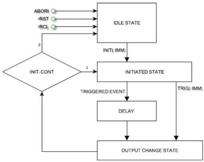
flowchart
graph TD
    A["ABORI"] --> B["IDLE STATE"]
    C["RST"] --> B
    D["RCL"] --> B
    B --> E["INITI: IMM"]
    E --> F["INITIATED STATE"]
    F --> G["TRIGGERED EVENT"]
    G --> H["DELAY"]
    H --> I["OUTPUT CHANGE STATE"]
    I --> J["0"]
    J --> K{INIT: CONT}
    K --> L["1"]
    L --> F
    F --> M["TRIGI: IMM"]
Fig.8-1: Simplified Models of FIX Mode
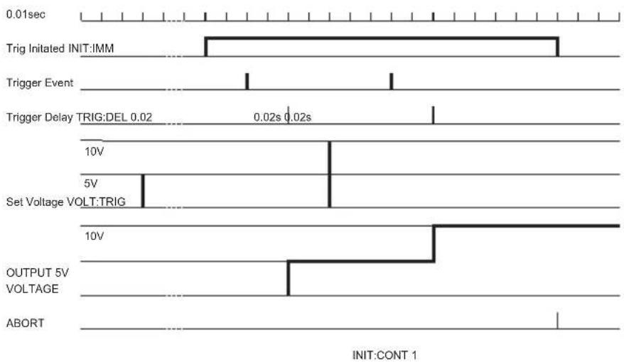
other
| Signal Event | Description | | ------------ | --------------------------------- | | Initiated INIT:IMM | Trigger Initiated INIT:IMM | | Event | Trigger Event | | Delay | Trigger Delay TRIG:DEL 0.02 | | 10V | Set Voltage VOLT:TRIG | | 5V | Set Voltage VOLT:TRIG | | 10V | OUTPUT 5V VOLTAGE | | ABORT | ABORT |Fig.8-2: Fix Mode Sequence example
8.3 LIST Mode
Output change value in step determined by parameters in the LIST subsystem via input trigger. Refer to section 7.12.8
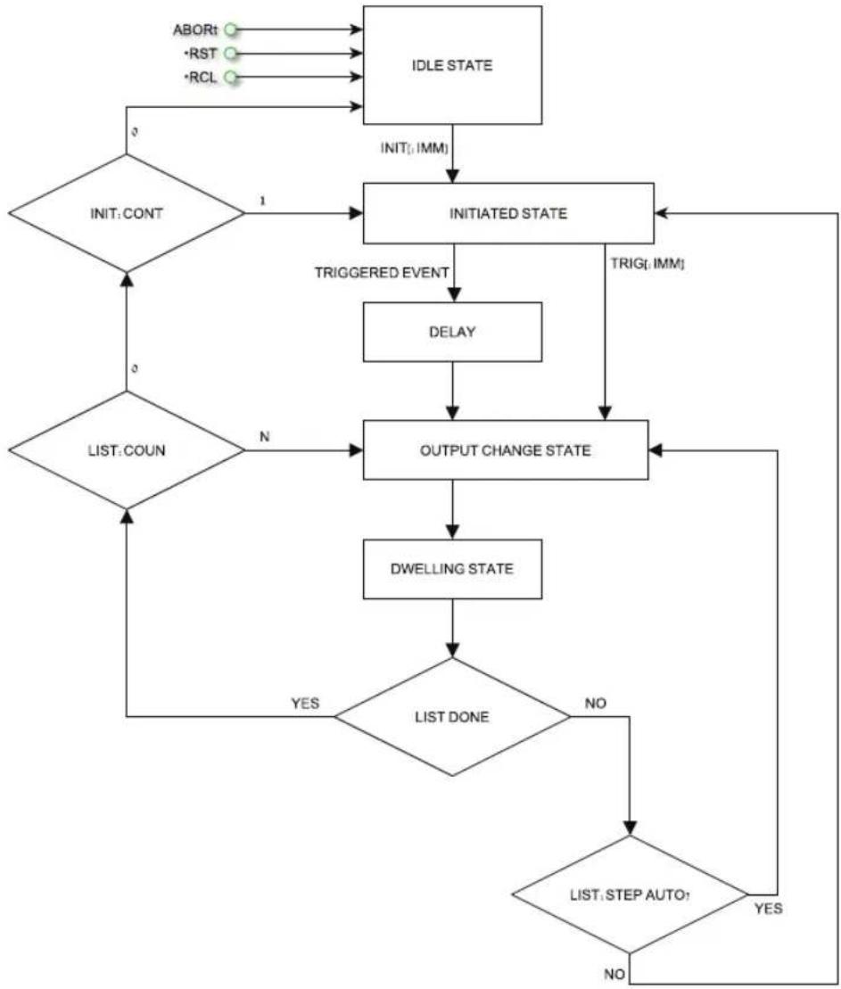
flowchart
graph TD
    A["ABORT"] --> B["IDLE STATE"]
    C["RST"] --> B
    D["RCL"] --> B
    B --> E["INIT: IMM"]
    E --> F["INITIATED STATE"]
    F --> G["TRIGGERED EVENT"]
    G --> H["DELAY"]
    H --> I["OUTPUT CHANGE STATE"]
    I --> J["DWELLING STATE"]
    J --> K{LIST DONE}
    K -->|YES| L["LIST: COUN"]
    K -->|NO| M{LIST: STEP AUTO?}
    M -->|YES| N["End"]
    M -->|NO| O["End"]
    F --> P["INIT: CONT"]
    P --> Q["1"]
    Q --> F
    P --> R["0"]
    R --> S["0"]
    S --> T["LIST: COUNT"]
    T --> U["N"]
    U --> I
Fig.8-3: Simplified Models of LIST Mode
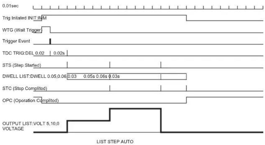
other
| Signal | Value | | --- | --- | | Trig Initiated INIT:IMM | 0.01sec | | WTG (Wait Trigger) | 0.02s | | Trigger Event | 0.02s | | TDC TRIG:DEL 0.02 | 0.02s | | STS (Step Started) | 0.03s | | DWELL LIST:DWELL 0.05,0.06 | 0.03s | | STC (Step Complited) | 0.03s | | OPC (Operation Complited) | 0.03s | | OUTPUT LIST:VOLT 5,10,0 VOLTAGE | 5,10,0 |Fig.8-4: LIST Mode Sequence example
8.4 WAVE Mode
Output change value in slope determined by parameters in the WAVE subsystem via input trigger. Refer to section 7.12.12.
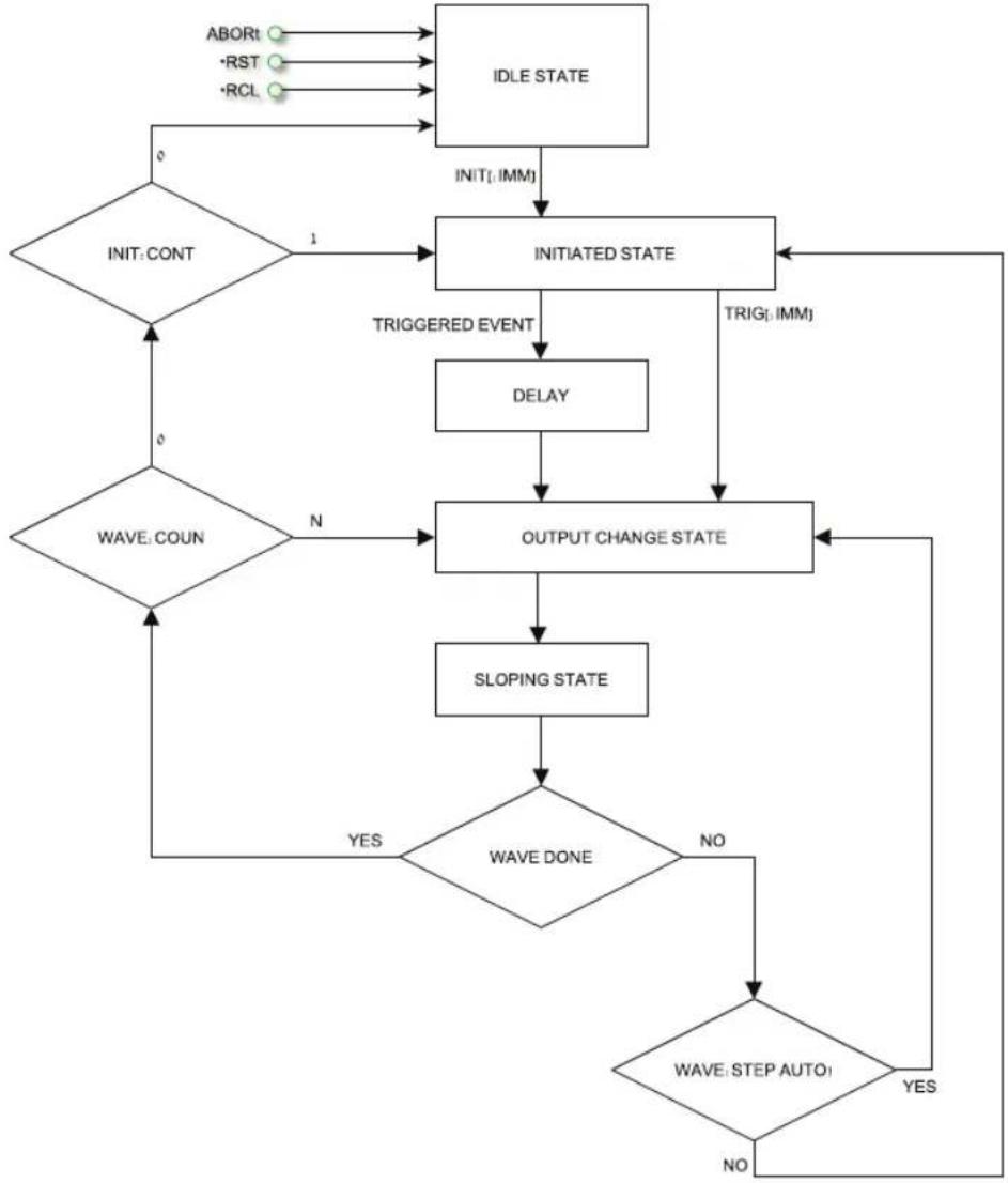
flowchart
graph TD
    A["ABORT"] --> B["IDLE STATE"]
    C["RST"] --> B
    D["RCL"] --> B
    B --> E["INIT CONT"]
    E --> F{1}
    F --> G["INITIATED STATE"]
    G --> H["TRIGGERED EVENT"]
    H --> I["DELAY"]
    I --> J["OUTPUT CHANGE STATE"]
    J --> K["SLOPING STATE"]
    K --> L{WAVE DONE}
    L -->|YES| M["WAVE: COUN"]
    L -->|NO| N["WAVE: STEP AUTO1"]
    N --> O{0}
    O --> P["INIT [IMM"]]
    P --> G
    Q["TRIG [IMM"]] --> G
    R["0"] --> S{0}
    S --> T["INIT CONT"]
    T --> U{1}
    U --> V["INITIATED STATE"]
    V --> W["TRIGGERED EVENT"]
    W --> X["DELAY"]
    X --> Y["OUTPUT CHANGE STATE"]
    Y --> Z["SLOPING STATE"]
    Z --> AA{0}
    AA -->|YES| AB["WAVE: COUN"]
    AA -->|NO| AC{0}
    AC --> AD["INIT CONT"]
Fig.8-5: Simplified Models of Trigger in WAVE Mode
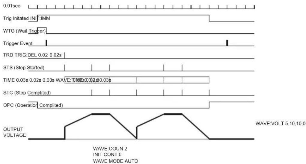
other
| Signal Type | Value | | ----------------------- | ------------ | | Output Voltage | VOLT | | WAVE: COUN 2 | 5.10,10.0 | | INIT CONT 0 | 0 | | WAVE MODE AUTO | 0 |Fig.8-6: WAVE Mode Sequence example
8.5 Trigger
| Subsystem Level | Display Function Level Display Parameter Level Display Description | |||||
| Trigger Setting | tr.10 | INIT | in it | INIT | in it | Initialization(Refer to command INIT)ready for trigger. |
| TRIG | tr.10 | |||||
| Continue | Cont | ENA | EnR | refer to commandINIT:CONT | ||
| DIS | d.5 | |||||
| Trigger IN (input trigger) | tr.in | BUS (via Software or front Panel), | BUS | refer to command TRIG:SOUR | ||
| EXT (Analog) | EHT | |||||
| Trigger delay | tr.dL | 0-65sec | 0.100 | refer to command TRIG:DELAY.Fine and Course modes | ||
| Trigger OUT | tr.0u | OFF | OFF | refer to command OUTP:TTLT:MODE | ||
| Trigger | tr.10 | |||||
| Function Strobe | F.Str | |||||
| Programming | Prog | LOAD List or Wave data | LOAD | L1...L4 | L2 | Refer to commands LIST:LOAD and WAVE:LOAD |
| COUNter (set repeat time) | COUN | 1...9999 | 12 | (Refer to LIST:COUN and WAVE:COUN) allow course and fine setting | ||
| STEP setting | STEP | ONCE | ONCE | (Refer to LIST:STEP and WAVE:STEP) | ||
| AUTO | AUTO | |||||
| ABORt execution | Abor | YES | YES | (Refer to command ABORt) | ||
Table 8-1: Trigger and Programming front panel menu
NOTE:
At AC power ON the display shows last selected program list but doesn't load it from memory.
NOTE:
If during program selection L1-L4, display shows "Err" message then program memory is empty or power supply is in initiated state. Select "ABORt" to EXIT from initiate state.
8.5.1 Input Trigger
Trigger source can be set via:
- BUS - Command (Refer to section 7.11 *TRG, 7.12 TRIGger) or Front Panel.
- EXT - Rear panel connector J3-8 (Refer to section 4.3.2).
Input Trigger source setting via Front Panel:
- Press MENU button. MENU (green) LED illuminates. "5E" message appears on the Voltage display.
- Rotate Voltage encoder until "E r i G" message appears on Voltage display.
- Press Voltage encoder. "in" message appears on Voltage display.
- Rotate Voltage encoder until "tr .in " message appears. Press Voltage encoder.
- "E" in" message appears on Voltage Display and "EHE" or "BUS" messages appear on Current display. Rotate to scroll list and press Current encoder to select.
8.5.2 Output Trigger
Rear panel connector J3-3 (Refer to section 4.3.2). There are three output trigger modes: Programming Mode NONE, FIX:
- OFF – No Trigger out.
• In TRIG mode, trigger is generated when output status changes.
- In Function Strobe mode, an output pulse is generated automatically any time an output parameter such as output, voltage or current is programmed.
Programming modes LIST or WAVE:
- OFF – No Trigger out.
• In TRIG mode, trigger is generated when LIST or WAVE is completed.
• In Function Strobe mode, an output pulse is generated automatically any time a step is competed.
Output Trigger mode settings:
- Press MENU button. MENU (green) LED illuminates. "SET" message appears on the Voltage display.
- Rotate Voltage encoder until "E r, G" message appears.
- Press Voltage encoder. "in it" message appears on Current display.
- Rotate Voltage encoder until "Er .0u" message appears. Press Voltage encoder.
- "tr.0u" message appears on Voltage Display and "OFF", "tr.0U", "F.5Er" messages appear on Current display. Rotate to scroll list and press Current encoder to select.
8.6 Transient Waveform Example
8.6.1 Wave Programming
- Select required transient operation mode Insert communication command (Example: VOLT:MODE WAVE).
- Set Voltage values Insert communication command (Example: WAVE:VOLT 5,10,10,0).
- Set Timing values Insert communication command (Example: WAVE:TIME 0,2,3,2).
- Set Counter value for sequence execution (Example: WAVE:COUN 2).
- Set Step parameter AUTO or ONCE (Example: WAVE:STEP AUTO).
- In this step possible store program in memory and continue programming without PC connection Insert communication command (Example: WAVE:STORe 2).
- Recycle AC power. Set OUT ON.
8.6.2 Wave Execution via Communication PC
- Load stored data Insert communication command (Example: WAVE:LOAD 2)
- Set COUNTER (How many times program will be repeated if STEP in AUTO mode). Insert communication command (Example: WAVE:COUN 2)
- Set Trigger IN source (BUS for Command or Front Panel and EXT via Rear Panel J3-8 pin) Insert communication command (Example: TRIG:SOUR BUS)
- Set Trigger Initialize Continue mode (If 1 then after program execution power supply will be ready for next trigger. If 0 then send INIT command to get to the next trigger. Insert communication command (Example: INIT:CONT 1)
- Send INIT command. (Power supply ready for TRIGGER). Insert communication command (Example: INIT).
- Send *TRG command or press Current encoder.
NOTE:
In order to be able to change the transient operation mode while the power supply is ready for trigger and not in an idle state, send ABORt and then set INIT:CONT 0.
8.6.3 Wave Execution via Front Panel
- Load stored data MENU -> "Pr-0G" -> "LOAD" -> L2
- Set Trigger IN source (BUS for Command or Front Panel and EXT via Rear Panel J3.2 pin) MENU -> "tr.iG" -> "tr.ln" -> "bUS"
- Set Trigger Initialize Continue mode (If 1 then after program execution power supply will be ready for the next trigger. If 0 then send INIT command MENU -> "EniG" -> "ConE" -> "EnB" to get to the next trigger.
- Set INIT command. (Power supply ready for TRIGGER) MENU -> "tr, 5" -> "in, 1E" -> "in, 1E"
- Exit from MENU and Press Current encoder to trigger.
8.7 Additional Examples
8.7.1 List Example
TRIG:SOUR BUS Select trigger source external analog signal
VOLT:MODE LIST Select sequence mode "LIST"
LIST:VOLT 2,4,2,8,5,4 Set voltage values "2,4,2,8,5,4" Volts
LIST:DWEL 0.5,0.5,1,1,1,1 Set dwell values "0.5,0.5,1,1,1,1" seconds
LIST:COUN 1 Set list execution time "1"
LIST:STEP AUTO Set step execution mode "AUTO"
INIT:CONT OFF Trigger subsystem enabled for a single trigger action
INIT Trigger initializing
*TRG Trigger command
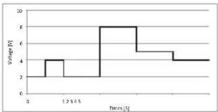
line
| Time [s] | Value | | -------- | ----- | | 0 | 2 | | 12.345 | 4 | | 23.675 | 8 | | 36.905 | 5 | | 49.235 | 4 |8.7.2 Waveform Example
TRIG:SOUR BUS Select trigger source via communication
interface or front panel
VOLT:MODE WAVE Select sequence mode "WAVE"
WAVE:VOLT 2,2,4,4,9,9,3,3 Set voltage values "2,2,4,4,9,9,3,3" Volts
WAVE:TIME 0,1,0.5,0.5,0.5,0.5,1.5,1 Set time values "0,1,0.5,0.5,0.5,0.5,1.5,1" seconds
WAVE:COUN 2 Set wave execution time "2"
WAVE:STEP AUTO Set step execution mode "AUTO"
INIT:CONT ON Trigger system is continuously enabled
INIT Trigger initializing
*TRG Trigger command
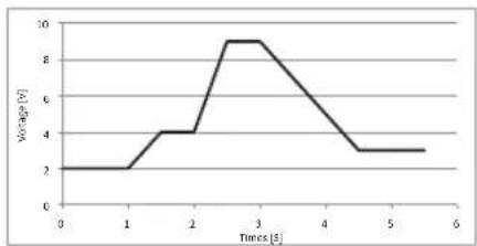
line
| Times [s] | Voltage [V] | | --------- | ----------- | | 0 | 2 | | 1 | 2 | | 2 | 4 | | 3 | 9 | | 4 | 6 | | 5 | 3 | | 6 | 3 |NOTE:
For an easy way to create arbitrary waveforms, you can use the "Z" Waveform Creator" Application that can be installed from the CD-ROM shipped with the product. (for further information, see the 'Quick Start Guide' on the CD-ROM).
CHAPTER 9: STATUS, FAULT AND SRQ REGISTERS
9.1 General
This section describes various status errors (faults) and SRQ register structures. The registers can be read or set via the RS232/485/USB commands. Refer to Fig.9-1 for the Status and Fault Registers Diagram.
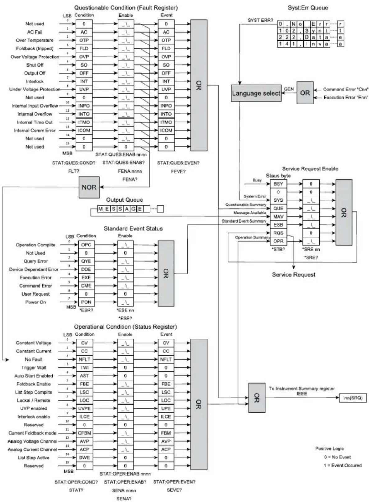
flowchart
graph TD
    subgraph Questionable Condition (Fault Register)
        A["LSB Condition"] --> B["0"]
        C["AC Fail"] --> D["1"]
        E["Over Temperature"] --> F["2"]
        G["Foldback (tripped)"] --> H["3"]
        I["Over Voltage Protection"] --> J["4"]
        K["Shut Off"] --> L["5"]
        M["Output Off"] --> N["6"]
        O["Interlock"] --> P["7"]
        Q["Under Voltage Protection"] --> R["8"]
        S["Not used"] --> T["9"]
        U["Internal Input Overflow"] --> V["10"]
        W["Internal Overflow"] --> X["11"]
        Y["Internal Time Out"] --> Z["12"]
        AA["Internal Comm Error"] --> AB["13"]
        AC["Not used"] --> AD["14"]
        AE["Not used"] --> AF["15"]
        AG["MSB"] --> AH["0"]
        AI["NOT"] --> AJ["INPO"]
        AK["INTO"] --> AL["ITMO"]
        AM["ICOM"] --> AN["0"]
        AO["0"] --> AP["0"]
        AQ["NOR"] --> AR["STAT:QUES:ENAB nnnn"]
        AS["FLT?"] --> AT["STAT:QUES:ENAB?"]
        AU["FENA nnnn"] --> AV["FENA?"]
    end

    subgraph Service Request Enable
        AW["OR Request Enable"] --> AX["STaus byte"]
        AX --> AY["BSY"]
        AX --> AZ["SYS"]
        AX --> BA["QUE"]
        AX --> BB["MAV"]
        AX --> BC["ESB"]
        AX --> BD["RQS"]
        AX --> BE["*STB?"]
        AX --> BF["*SRE nn"]
        AX --> BG["Syst:Err Queue"]

    end

    subgraph Operational Condition (Status Register)
        BH["Operational Condition (Status Register)"]
        BI["Constant Voltage"] --> BJ["LSB Condition"]
        BK["Constant Current"] --> BL["CC"]
        BM["No Fault"] --> BN["NFLT"]
        BO["Trigger Wait"] --> BP["TWI"]
        BQ["Auto Start Enabled"] --> BR["AST"]
        BS["Foldback Enable"] --> BT["FBE"]
        BU["List Step Complete"] --> BV["LSC"]
        BW["Lockal / Remote"] --> BX["LOC"]
        BY["UVP enabled"] --> BZ["UVPE"]
        CA["Interlock enable"] --> CB["ILCE"]
        CC["Current Foldback mode"] --> CD["CFBM"]
        DE["Analog Voltage Channel"] --> FD["AVP"]
        DG["Analog Current Channel"] --> DH["ACP"]
        DI["List Step Active"] --> DJ["DWE"]
        DK["Reserved"] --> DL["0"]
        DM["NOR"] --> DN["NOR"]

    end

    A --> OR
    B --> OR
    AC --> OR
    AD --> OR
    AE --> OR
    BH --> OR
    BI --> OR
    BJ --> OR
    BK --> OR
    BL --> OR
    BN --> OR
    BP --> OR
    DB --> OR
    DC --> OR
    DD --> OR
    DL --> OR
    DJ --> OR
    DLN --> OR

    style Questionable Condition fill:#f9f,stroke:#333
    style Operational Condition fill:#bbf,stroke:#333
Fig.9-1: Status and Fault Registers Diagrams (SCPI)
9.2 Power Supply Status Structure
Status and Fault Register shows the status register structure of the power supply. The Standard Event, Status Byte, and Service Request Enable registers and the Output Queue perform standard functions as defined in the IEEE 488.2 Standard Digital Interface for Programmable Instrumentation. The Operation Status and Questionable Status registers implement status functions specific to the power supply.
9.3 Condition Registers
There are two registers that the user may read to see the condition of the supply. The register bits are set to show a fault or if an operating mode is active. The bits are cleared when the fault or mode is cleared. The registers are read-only.
9.3.1 Fault Register
The fault register sets a bit when a Fault occurs (Refer to table 9-1). The bit is cleared when the fault condition is removed.
Bit Number Decimal Value Bit Symbol Description
| 0 | 1 |
| 1 2 AC AC Fail | |
| 2 4 OTP Over Temperature | |
| 3 8 FLD Fold Back Protection | |
| 4 16 OVP Over Voltage Protection | |
| 5 32 SO Shut Off | |
| 6 64 OFF Output Off | |
| 7 128 INT Interlock | |
| 8 256 UVP Under Voltage Protection | |
| 9 512 0 Not used | |
| 10 1024 INPO Internal Input Overflow * | |
| 11 2048 INTO | Internal Overflow * |
| 12 4096 ITMO | Internal Time Out * |
| 13 8192 ICOM | Internal Comm Error * |
| 14 to 15 | N/A 0 Not used |
Table 9-1: Bit Configuration of Questionable Registers
9.3.2 Status Register
The status register sets a bit when status changes (Refer to Table 9-2). The bit is cleared when the condition is removed.
Bit Number Decimal Value Bit Symbol Description
| 0 1 CV Set high if Constant Voltage Operation | ||
| 1 2 CC Set high if Constant Current Operation | ||
| 2 4 NFL No fault | ||
| 3 8 TW Trigger wait | ||
| 4 16 AST Auto Start Enabled | ||
| 5 32 FBE Foldback enable | ||
| 6 64 LSC List step complete | ||
| 7 128 LOC Local / Remote | ||
| 8 256 UVP Ena Under voltage Protect enabled | ||
| 9 512 ILC Ena Interlock Enabled | ||
| 10 1024 | ||
| 11 2048 FBC Foldback CC mode enabled | ||
| 12 4096 AVP Remote Analog Voltage Programming mode | ||
| 13 8192 ACP | Remote Analog Current Programming mode | |
| 14 16384 | DWE | The list step is active (dwelling) |
| 15 32768 | Reserved | |
Table 9-2: Bit Configuration of Operation
9.4 Conditional, Enable and Event Registers
9.4.1 Conditional Registers.
The condition registers show a snapshot of the power supply state at the present time. Some faults or mode changes occur and clear quickly before the control computer can detect them. The change may be latched in EVENT REGISTERS so the computer can detect them even if they cleared quickly.
9.4.2 Event Registers.
Bits are sent to the Event register when a fault or mode change occurs. The bit remains set until the control computer reads the Event register or clears it. The control computer cannot tell if the fault or mode change occurred more than once since the last time the Event register was read.
9.4.3 Enable Register
The Status and Fault Enable registers are set by the user to enable SRQs in the event of changes in power supply status or fault.
9.5 Service Request
A SRQ will be sent when the contents of at least one of the event registers changes from all zeroes to any bit(s) set. When SRQ occurs, power supply sends "!nn" message (nn-power supply address).
9.6 Standard Event Status Group
9.6.1 Register Functions
This group consists of an Event register and an Enable register that are programmed by COMMON commands. The Standard Event register latches events relating to interface communication status. It is a read-only register that is cleared when read. The Standard Event Enable register functions similarly to the Enable registers of the Operation and Questionable status groups.
9.6.2 Register Commands
The common *ESE command programs specific bits in the Standard Event Status Enable register. Because the power supply implements *PSC, the register is cleared at power on if *PSC = 1.
*ESR? reads the Standard Event Status Event register. Reading the register clears it.
Bit Signal Meaning
| 0 OPC Operation complete |
| 2 QYE Query error |
| 3 DDE Device-dependent error |
| 4 EXE Execution |
| 6 CME Command error |
| 7 PON Power on |
Table 9-3: Standard Event Status Group
Operation Complete
Set whenever the last command is completed and the software is ready to accept another command, or when query results are available.
Query Error
Set when a query is made for which no response is available.
Device Dependent Error
Set for device specific errors. These errors are entered in the System Error Queue and have error codes greater than 0. See Table 9-6 for error descriptions.
Execution Error
Set when a parameter exceeds its allowed range.
Command Error
Set for a syntax error.
Power On
Set once at power-up. The Status Byte ESR bit is not set.
This register summarizes the information from all other status groups as defined in the IEEE 488.2 Standard Digital Interface for Programmable Instrumentation standard. The register can be read either by a serial poll or by *STB?. Both methods return the same data, except for bit 6. Sending *STB? return MSS in bit 6, while polling returns RQS in bit 6. The *CLS command will clear the Status Byte.
Bit Signal Meaning
| 0 BSY Busy bit | |
| 1 0 Not used | |
| 2 SYS System Error | |
| 3 QUES Questionable Status summary bit | |
| 4 MAV Message Available summary bit | |
| 5 ESB Event Status summary bit | |
| 6 MSS | Master Status summary bit |
| RQS | Request Service bit |
7 OPER Operation Status summary bit
Table 9-4: Status Byte Register
Error Information Available
This bit is set when any error is entered in the System Error queue. It is read using the SYSTem:ERRor?Query.
Message Available
Indicates a message is available in the GPIB output queue. This bit is cleared then the GPIB output buffer is read.
Standard Event Status Register
This is a summary bit for the ESR. It is set when any of the ESR bits are set, and cleared when the ESR is read.
The RQS Bit
Whenever the power supply requests service, it sets the SRQ interrupt line true and latches RQS into bit 6 of the Status Byte register. When the controller services the interrupt, RQS is cleared inside the register and returned in bit position 6 of the response. The remaining bits of the Status Byte register are not disturbed.
The MSS Bit
This is a real-time (unlatched) summary of all Status Byte register bits that are enabled by the Service Request Enable register. MSS is set whenever the power supply has at least one or more reasons for requesting service. Sending *STB? reads the MSS in bit position 6 of the response. No bits of the Status Byte register are cleared by reading it.
9.6.4 Determining the Cause of a Service Interrupt
You can determine the reason for an SRQ by the following actions:
Use a serial poll or the *STB? query to determine which summary bits are active.
Read the corresponding Event register for each summary bit to determine which events caused the summary bit to be set. When an Event register is read, it is cleared. This also clears the corresponding summary bit.
The interrupt will recur until the specific condition that caused the event is removed. If this is not possible, the event may be disabled by programming the corresponding bit of the status group Enable register. A faster way to prevent the interrupt is to disable the service request by programming the appropriate bit of the Service Request Enable register.
9.6.5 Output Queue
The Output Queue is a first-in, first-out (FIFO) data register that stores power supply-to-controller messages until the controller reads them. Whenever the queue holds one or more bytes, it sets the MAV bit (4) of the Status Byte register. If too many unread error messages are accumulated in the queue, a system error message is generated. The Output Queue is cleared at power On and by *CLS.
9.6.6 Error Messages
System Error Messages are read back via the SYST:ERR? query. The error number is the value placed in the power supply error queue. SYST:ERR? returns the error number into a variable and combines the number and the error message into a string. Table 9-5 lists the system errors that are associated with SCPI syntax errors and interface problems. Information within the brackets is not part of the standard error message, but is included for clarification. When system errors occur, the Standard Event Status register records them as follows:
Bit Set Error code Error Type Bit Set Error code Error type
5 -100 thru -199 Command 3 -300 thru -399 Device-dependent
4 -200 thru -299 Execution 2 -400 thru -499 Query
Table 9-5: Standard Event Status Register Error Bits
The Status and Error Registers described in the previous section are only one of the status methods in the IEEE board. There is also a SCPI requirement for error messages that are in the form of:
The user sends the "SYST:ERR?" query to read the error message. The messages are stored in a first-in/first-out queue.
The SYST:ERR queue can buffer up to TEN error messages, although the tenth is replaced by the -350,"Queue Overflow" if an eleventh message is generated. After the queue overflow, only the first ten messages are stored and the later messages are lost.
The SYST:ERR queue is cleared by:
Reading the messages one at a time using "SYST:ERR?" until 0, "No error" is read, or The *CLS (Clear Status) command.
If any message is in the SYST:ERR queue (except "No error"), then bit 2 of the Status Byte is set. A Service Request is generated if bit 2 is enabled.
| Error Number | Error Description Error Event | |
| 0 "No Error" No Error Reported | ||
| -100 "Command Error" Unit Receives Command With Unspecified Error. | ||
| -101 "Invalid Character" | A Character Was Received That Is Not: A-Z, A-Z, 0-9, ?, *, ;, Period, Space, CR, LF. | |
| -104 "Data Type Error" | IEEE Receives Command Parameter With Wrong Type Of Data. Example: Receives Letter Where Number Expected. | |
| -109 "Missing Parameter" Valid Command Received But Not Enough Characters. | ||
| -131 "Invalid Suffix" Unrecognized Units, Or Units Not Appropriate | ||
| -200 Execution Error | Generic. This is the generic syntax error for devices that can not detect more specific errors. | |
| -222 "Data Out Of Range" Attempt To Program Voltage, Current Or OVP Beyond Supply Limits. | ||
| -223 "Too Much Data" Out Of Memory; Block, String, Or Expression Too Long | ||
| -241 "Hardware Missing" | When Operating In Multi Drop Mode, An Attempt Was Made To Address A Non-Existent Supply. (only for IEEE and LAN) | |
| -284 "Program Currently Running" Occur when the device was initiated by "INIT" command. | ||
| -286 "Data Load Empty" Data doesn't saved in List or Wave cell | ||
| -350 "Queue Overflow" | Too Many SYST:ERR Messages Are Stored In This Queue And The Newest Messages Are Discarded | |
| 301 | "PV Above OVP" | Attempt To Program Voltage Above OVP Setting. |
| 302 | "PV Below UVL" | Attempt To Program Voltage Below UVL Setting. |
| 304 | "OVP Below PV" | Attempt To Set OVP Below Voltage Setting. |
| 305 | "UVL Below Zero" | Attempt To Set UVL Above Voltage Setting. |
| 306 | "UVL Above PV" | Attempt To Set UVL Above Voltage Setting. |
| 307 | "On During Fault" Attempt To Turn Supply Output ON When A Fault Exists. | |
| 320 | "Under-Voltage Shutdown" | Under Voltage Shutdown Occurred |
| 321 | "AC Fault Shutdown" | Brown-Out Or Phase-Loss Shutdown Occurred |
| 322 | "Over-Temperature Shutdown" | Over-Temperature Shutdown Occurred |
| 323 | "Fold-Back Shutdown" | Fold-Back Shutdown Occurred |
| 324 | "Over-Voltage Shutdown" | Over Voltage Shutdown Occurred |
| 325 | "Analog Shut Off Shutdown" | Shut Off Occurred From Rear Panel |
| 326 | "Output-Off Shutdown" | Output-Off Occurred From Front Panel Button |
| 327 | "Interlock Open Shutdown" | Interlock Open Occurred From Rear Panel |
| 329 | "SLAD mode" | Cannot execute command in Advanced Slave mode. |
| 340 | "Internal Message Fault" | General Non-Specified Internal Message Fault |
| 341 | "Input Overflow" | Receive Buffer over 500 chars |
| 342 | "Internal Overflow" | Serial Receive Buffer In IEEE Is Full Because Supply Sent Too Many Characters |
| 343 | "Internal Timeout" | IEEE Did Not Receive Response From Supply Before Timeout Period |
| 344 | "Internal Checksum" | IEEE Received Checksum Error, From Supply. |
| 399 | "Unknown Error" | No Known Error. |
| -400 "Query Error" | This Is The Generic Error For The Power Supply, Used Only When The Other Types Of Error Do Not Apply | |
| -410 "Query INTERRUPTED" | Generated When A New Command Was Received Before It Could Finish The Query. | |
Table 9-6: Error Table
CHAPTER 10: ISOLATED ANALOG PROGRAMMING OPTION
10.1 Introduction
Isolated Analog Programming is an internal option card for analog programming of the Z^+ Power Supply series. The option is factory installed and cannot be obtained with GPIB (IEEE) Interface. Output Voltage and Current Limit can be programmed and readback through optically isolated signals which are isolated from all other ground references in the power supply.
There are two types of Isolated Analog programming cards:
-
0-5V/0-10V option (PN: IS510): Using 0-5V or 0-10V signals for programming and readback.
-
4-20mA option (PN: IS420): Using current signals for programming and readback.
10.2 Specifications
10.2.1 0-5V/0-10V Option (PN: IS510)
| Programming Inputs | Output voltage programming accuracy % +/-1 | ||
| Output current programming accuracy % +/-1 | |||
| Output voltage programming temperature coefficient PPM/ C +/-100 | |||
| Output current programming temperature coefficient PPM/ C +/-100 | |||
| Input impedance Ohm 1M | |||
| Absolute maximum voltage Vdc 0-15 | |||
| Max. voltage between program inputs and supply outputs Vdc 400 | |||
| Monitoring Outputs | Output voltage monitoring accuracy | % +/-1.5 | |
| Output current monitoring accuracy | % +/-1.5 | ||
| Output Impedance (see note) | Ohm 100 | ||
| Max. voltage between monitoring outputs and supply outputs | Vdc | 400 |
NOTE:
Use 100Kohm minimum input impedance for the monitoring circuits to minimize the readback error.
10.2.2 4-20mA Option (PN: IS420)
| Programming Inputs | Output voltage programming accuracy % +/-1 | ||
| Output current programming accuracy % +/-1 | |||
| Output voltage programming temperature coefficient PPM/ C +/-200 | |||
| Output current programming temperature coefficient PPM/ C +/-200 | |||
| Input impedance Ohm 50 | |||
| Absolute maximum input current | mA | 0-30 | |
| Max. voltage between program inputs and supply outputs Vdc 400 | |||
| Monitoring Outputs | Output voltage monitoring accuracy | % +/-1.5 | |
| Output current monitoring accuracy | % +/-1.5 | ||
| Maximum load impedance | Ohm 500 | ||
| Max. voltage between monitoring outputs and supply outputs | Vdc | 400 |
10.3 Isolated Programming & Monitoring Connector
Refer to Table 10-1 for detailed description of the Rear Panel Isolated Programming & Monitoring connector. To provide the lowest noise performance, it is recommended to use shielded-twisted pair wiring.
Refer to Fig.10-1 for description of the connector.
Isolated programming plug P/N: MC1.5/8-ST-3.81, Phoenix.
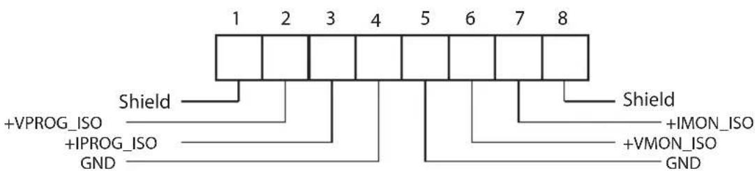
Fig.10-1: Isolated Programming & Monitoring connector
| Terminal Signal name Function | Range 0-5/0-10V IS510 option | Range 4-20mA IS420 option | ||
| 1 SHLD | Shield, connected internally to chassis of the supply. | Chassis ground | ||
| 2 | +VPROG_ISO | Output voltage programming input 0-5/0-10V 4-20mA | ||
| 3 +IPROG_ISO Output current | programming input 0-5/0-10V 4-20mA | |||
| 4 GND Ground for programming signals. Ground Ground | ||||
| 5 GND Ground for programming signals. Ground Ground | ||||
| 6 +VMON_ISO Output voltage | monitoring output 0-5/0-10V 4-20mA | |||
| 7 +IMON_ISO Output current | monitoring output 0-5/0-10V 4-20mA | |||
| 8 SHLD | Shield, connected internally to chassis of the supply. | Chassis ground | ||
Table 10-1: Detailed description of the Rear Panel Isolated Programming & Monitoring connector.
CAUTION:
When the Isolated Analog Option is installed, do not apply any signals to the non-isolated VPGM and IPGM (J1-6 and J1-5) pins. All other J1 features may be used normally. Refer to Section 4.3.1 for a description of J1 features.
Parallel operation: Optional Isolated Analog IS510/IS420 must be installed in both the Master and Slave units.
10.4 Setup and Operating Instructions
CAUTION:
To prevent damage to the unit, do not program the output voltage and current to higher than the power supply rating.
10.4.1 Setting Up Power Supply for 0-5/0-10V Isolated Programming and Monitoring
Perform the following procedure to configure the power supply:
- Turn the power supply AC power switch to Off.
- Short pins J1-1 to J1-7, and turn AC power switch to On.
- Press MENU button. MENU (GREEN) LED illuminates. "SE" message appears on Voltage display.
- Press Voltage encoder. "UOLE" message appears on Voltage Display and "Curr" appears on the Current display.
- Press Voltage encoder to select programming of the Output Voltage, or press Current encoder to select programming of the Output Current.
- The selected function appears on the Voltage display. Parameter "F .PAN" or "E.UOL" or "Er-ES" appears on the Current display.
- Rotate and press the Current encoder to select "E .UOL".
- "UOLE" message appears on Voltage Display and "Curr" appears on the Current display.
- Rotate Voltage encoder until "-RNG" appears on Voltage display. Press on the Voltage encoder.
- "RANG" appears on Voltage display and "5" (5V) or "10" (10V) appears on Current display.
- Rotate and press the Current encoder to select the desired programming Voltage range.
- Press MENU button twice to return display to it's previous state. MENU LED turns OFF
- Connect the programming sources to the mating plug of the Isolated Programming connector. Observe for correct polarity of the voltage source.
- Set the programming sources to the desired levels and turn the power supply ON.
NOTE:
J1-1 and J1-7 must be shorted together with a jumper.
10.4.2 Setting Up Power Supply for 4-20mA Isolated Programming and Monitoring
The set up procedure of 4-20mA Isolated Programming and Monitoring is the same as section 10.4.1 except "r-ANG" setting. "r-ANG" setting must be set to "IO"(10V).
CAUTION:
To prevent damage to the unit, do not program the output voltage and current to higher than the power supply rating.
CHAPTER 11: MAINTENANCE
11.1 Introduction
This chapter provides information about maintenance, calibration and troubleshooting.
11.2 Units Under Warranty
Units requiring repair during the warranty period should be returned to a TDK Lambda authorized service facility. Refer to the address listings on the back cover of this manual. Unauthorized repairs performed by other than the authorized service facilities may void the warranty.
11.3 Periodic Maintenance
No routine maintenance of the power supply is required except for periodic cleaning. To clean, disconnect the unit from the AC supply and allow 30sec. for discharging internal voltage. The front panel and the metal surfaces should be cleaned using a mild solution of detergent and water. The solution should be applied onto a soft cloth, and not directly to the surface of the unit. Do not use aromatic hydrocarbons or chlorinated solvents for cleaning. Use low pressure compressed air to blow dust from the unit.
11.4 Adjustments and Calibration
No internal adjustment or calibration is required. There is NO REASON to open the power supply cover.
11.5 Parts Replacement and Repairs
As repairs are made only by the manufacturer or by authorized service facilities, no parts replacement information is provided in the manual. In case of failure, unusual or erratic operation of the unit, contact the TDK Lambda sales or service facility nearest you. Please refer to the TDK Lambda sales offices address listings on the back cover of this user manual.
11.6 Troubleshooting
If the power supply appears to be operating improperly, use the troubleshooting guide to determine whether the power supply, load or external control circuits are the cause.
Configure the power supply for basic front panel operation and perform the tests listed in Section 3.8 to determine whether the problem can be found with the power supply.
Table 11-1 provides the basic checks that can be performed to diagnose problems, and references to relevant sections of this manual for further information.
| SYMPTOM CHECK ACTION REF. | |||
| No output. All displays and indicators are blank. | Is the AC power cord defective? | Check continuity, replace if necessary. | 3.7 |
| Is the AC input voltage within range? | Check input AC voltage. Connect to appropriate voltage source. | 3.6 3.7 | |
| Output is present momentarily but shuts off quickly. The display indicates "RC". | Does the AC source voltage sag when load is applied? | Check input AC voltage. Connect to appropriate voltage source. | 3.6 |
| Output is present momentarily but shuts off quickly. the display indicates "DUP". | Is the power supply configured to Remote sense? | Check if the positive or negative load wire is loose. | 3.9.6 3.9.8 |
| Output voltage will not adjust. Front panel CC LED is on. | Is the unit in constant current mode? | Check current limit setting and load current. | 5.2.1 5.2.2 |
| Output voltage will not adjust. Front panel CV LED is on. | Check if output voltage is adjusted above OVP setting or below UVL setting. | Set OVP or UVL not to limit the output. | 5.3.2 5.3.3 |
| Output current will not adjust. Front panel CV LED is on. | Is the unit in constant voltage mode? | Check current limit and voltage settings. 5.2 | |
| Large ripple present in output. | Is the power supply in Remote sense? Is the voltage drop on the load wire high? | Check load and sense wire connections for noise and impedance effects. Minimize the drop on the load wires. | 3.9.4 3.9.8 |
| No output. Display indicates "DUP" | Over Voltage Protection circuit is tripped. | Turn off the AC power switch. Check load connections. If analog programming is used, check if the OVP is set lower than the output. | 5.3.2 |
| No output. Front panel PROT LED is blinking. | Display indicates "EnA" | Check rear panel J3 Interlock Function. | 5.7.2 |
| Display indicates "SO" | Check rear panel J3 Output Shut Off connection. | 5.7.1 | |
| Display indicates "OFP" | Check if air intake or exhaust are blocked. Check if the unit is installed adjacent to heat generating equipment. | 5.3.6 | |
| Display indicates "FOLD" Check FOLDback setting and load current. 5.3.4 | |||
| Poor Load regulation Front panel CV LED is on. | Are sensing wires connected properly? | Connect the sense wires according to User's Manual instructions. | 3.9.8 |
| The front panel controls are nonfunctional. | Is the power supply in Local-Lockout mode? | Turn Off the AC power and wait until the display turns off. Turn on the AC power and press front panel REM button. | 7.2.6 |
Table 11-1: Maintenance
11.7 Fuse Rating
There are no user replaceable fuses in the power supply. Internal fuses are sized for fault protection and if a fuse was opened it will indicate that service is required. Fuse replacement should be made by qualified technical personnel. Refer to Table 11-2 for a listing of the fuses.
| Z200/400 Input AC fuse F101 250VAC, 10A, Fast acting | |
| Z800 Input AC fuse F101 250VAC, 16A, Fast acting |
Table 11-2: Internal Fuse
11.1 Einleitung
ac cables 17 humidity 20, 24, 28, 32 safe start 61, 90, 101
ac fail 64 hyper terminal 90 safety 11
accessories 17 SCPI 82, 83, 94
acknowledge 87 I series operation 64
| address | 82, 89, 104 | Identification Commands | 88, 97 | shield | 17, 43, 44, 45 |
| auto restart | 61, 90, 101 | initialization | 89, 98, 124 | shut off | 55, 71, 72 |
| installation | 37 specifications | 18, 134 | |||
| B | interlock | 62, 71, 72, 93 | srq | 83, 127 | |
| backspace | 87 | isolated | 52, 134 | status command | 93, 96 |
| baud rate | 83 subsystem | 67, 71, 75, 101 |
L
C
| calibration | 137 | linking cable | 16, 17, 86 | TXD | 84, 87 |
| configuration | 82 | line feed | 87, 94 | TX (RS232) | 84 |
| checksum | 87, 88, 95, 133 | list mode | 109, 122 | trigger | 55, 100, 114, 124 |
| communication | 16, 17, 58, 82 | local operation | 60 | ||
| constant current | 40, 54, 60, 74 | local sensing | 39, 43, 45, 47 | U | |
| constant voltage | 40, 54, 60, 74 | UVL | 40, 63, 90, 92 | ||
| cooling | 16, 38 | M | UVP | 63, 64, 90, 92 |
D
| daisy-chain | 71, 86 | W | |||
| display | 50, 56, 108 | O | warranty | 10, 137 | |
| otp | 64 wave mode | 115, 123 | |||
| E | outline | 34, 35, 36 | wire size | 42 |
E
enable/disable 55,61,72 over voltage 40,62
error message 87, 113, 132
external resistor 80 P
external voltage 79 parallel operation 54,67
| parity | 87,94 | |
| F | PS_OK | 55,71,72,74 |
F
| fine 51,60 preview | 51,89 | |
| fix mode | 121 | |
| foldback | 41,63,68,90 | R |
| fuse | 11,138 | rack mounting 37 |
| front panel control | 50 rear panel | 50 |
| front panel lock | 51 remote sensing | 45,47,52 registers structure 127 |
| G | RS232 52,82,84 | |
G
| GEN protocol | 87 RS485 | 52, 82, 84 |
| grounding | 12, 47 | |
| global output command | 91 |
NOTES
NOTES
NOTES
NORTH AMERICA
TDK-Lambda Americas Inc.
3055 Del Sol Boulevard San Diego, CA 92154 U.S.A.
Tel: +1-619-575-4400
Fax: +1-619-575-7185
www.us.tdk-lambda.com/lp
UK
TDK-Lambda UK Ltd.
Kingsley Avenue Ilfracombe, Devon
EX 34 8ES United Kingdom
Tel: +44-1271-856666 Fax: +44-1271-864894
E-mail: powersolutions@uk.tdk-lambda.com
www.uk.tdk-lambda.com
FRANCE
TDK-Lambda France SAS
ZAC des Delaches
BP 1077 - Gometz le Chatel
91940 LES ULIS
Tel: +33 1 60 12 71 65
Fax: +33 1 60 12 71 66
E-mail: france@fr.tdk-lambda.com
www.fr.tdk-lambda.com
GERMANY
TDK-Lambda Germany GmbH
Karl-Bold-Str.40,
D-77855 Achern, Germany
Tel: +49-7841-666-0 Fax: +49-7841-500-0
E-mail: info.germany@de.tdk-lambda.com
www.de.tdk-lambda.com
AUSTRIA
TDK-Lambda Austria Sales Office
Aredstrasse 22,
A - 2544 Leobersdorf, Austria
Tel:+43-2256-65584 Fax:+43-2256-64512
E-mail: info.germany@de.tdk-lambda.com
www.de.tdk-lambda.com
ITALY
TDK-Lambda Italy Sales Office
Plant: 56 Haharoshet St
Karmiel Industrial Zone 2165158, Israel
Tel: +972-4-9887-491 Fax: +972-4-9583-071
www.tdk-lambda.co.il E-mail: info@tdk-lambda.co.il
JAPAN
TDK-Lambda Corporation
International Sales Division
Nittetsu Bldg. 6F, 1-13-1 Nihonbashi, Chuo-ku, Tokyo 103-0027, Japan
Tel: +81-3-5201-7175
Fax: +81-3-5201-7287
www.tdk-lambda.com
CHINA
Shanghai Branch of Wuxi TDK-Lambda Electronic Co. Ltd.
28F, Xingyuan Technology Building No.418, Guiping Road,
Shanghai, China 200233
Tel: +86-21-6485-0777 Fax: +86-21-6485-0666
www.cn.tdk-lambda.com
Beijing Branch of Wuxi TDK-Lambda Electronic Co. Ltd.
Room 12B11-12B12, Unit 7 DACHENG SQUARE, No.28
Xuanwumenxi Street, Xuanwu District Beijing, 100053, CHINA
Tel: +86-10-6310-4872 Fax: +86-10-6310-4874
www.cn.tdk-lambda.com
Shenzhen Branch of Wuxi TDK-Lambda Electronics Co.Ltd.
Room 4302, Excellence Times Square Building,
4068 Yi Tian Road, Futian District,
Shenzhen, China 518048
Tel: +86 -755-83588261 Fax: +86 -755-83588260
www.cn.tdk-lambda.com
KOREA
TDK-Lambda Corporation Seoul Office
8F Songnam Bldg, 1358-6, Seocho-Dong,
Seocho-Gu, Seoul, 137-862 KOREA
Tel:+82-2-3473-705
Fax: +82-2-3472-9137
www.tdk-lambda.co.kr
SINGAPORE
TDK-Lambda Singapore Pte.Ltd.
Blk 1008 Toa Payoh North # 07-01/03
Singapore 318996
Tel:+65-6251-7211 Fax:+65-6250-9171
www.tdk-lambda.com.sg
INDIA
TDK-Lambda Bangalore Office
526, Ground Floor, 10th Main, 7th Cross,
Jeevanbhimanagar,Bangalore 560 075
Karnataka,India
Tel: +91-80-43550 550
Fax: +91-80-43550 501
www.tdk-lambda.com.sg
MALAYSIA
TDK-Lambda Malaysia Sdn. Bhd.
c/o TDK (Malaysia) Sdn Bhd
Lot 709, Nilai Industrial Estate 71800 Nilai
www.tdk-lambda.com.my

TDK
TDK-Lambda EMEA
www.emea.tdk-lambda.com


- Programmable DC Power Supplies
- 200W/400W/600W/800W in 2U
- Built-in USB, RS-232 & RS-485 Interface
- Optional Interface:
- LXICompliantLAN
- IEEE488.2 SCPI (GPIB) Multi-Drop
- Isolated Analog Programming
- 200W/400W/600W/800W
- USER MANUAL
- Information Concerning Inclusion of Toxic and Hazardous Substances
- DECLARATION OF CONFORMITY Z+200, 400, 600 and 800 SERIES
- Table of Contents
- REGULATORY NOTICES 11
- SAFETY INSTRUCTIONS....11
- CHAPTER 1: GENERAL INFORMATION
- CHAPTER 2: SPECIFICATIONS
- CHAPTER 3: INSTALLATION
- CHAPTER 4: FRONT/REAR PANEL CONTROLS AND CONNECTORS
- CHAPTER 5: LOCAL OPERATION
- CHAPTER 6: REMOTE ANALOG PROGRAMMING
- CHAPTER 7: Serial RS232/RS485 and USB Interface
- CHAPTER 8: ADVANCED FUNCTIONS
- CHAPTER 9: STATUS, FAULT AND SRQ REGISTERS
- CHAPTER 10: ISOLATED ANALOG PROGRAMMING OPTION
- CHAPTER 11: MAINTENANCE
- USER MANUAL INDEX 141
- WARRANTY
- Limitation of Warranty
- Warranty Service
- Disclaimer
- Trademark Information
- REGULATORY NOTICES
- FCC Notice
- NOTE:
- WARNING:
- CE NOTICE (European Union)
- SAFETY APPROVALS
- OTHER
- SAFETY INSTRUCTIONS
- CAUTION:
- VORSICHT:
- ERDUNG
- NETZSTROMEINGANG
- SICHERUNG
- WARNUNG:
- Introduction
- General Description
- Models Covered by this Manual
- Features and Options
- Multiple Output Power System
- Control via the USB or RS232/485 Communication Ports
- Analog Voltage Programming and Monitoring
- Parallel Operation
- Output Connections
- Cooling and Mechanical Construction
- Accessories
- General
- Serial Link Cable
- Misc. Hardware
- AC Cables
- Serial Port Cables
- Z + 200 Series Specifications
- NOTES:
- Z + 400 Series Specifications
- Z+600 Series Specifications
- Z + 600 Series Specifications
- Z + 800 Series Specifications
- Supplemental Characteristics
- Z200W/400W/600W/800W Outline Drawing
- Z200W/400W/600W/800W Optional IEEE, Isolated Analog Interface Outline Drawing
- Z200W/400W/600W/800W Front Panel Output Binding Post Outline Drawing
- General
- Preparation for Use
- Initial Inspection
- Rack Mounting
- Location, Mounting and Cooling
- AC Source Requirements
- AC Input Cord
- Prior to Operation
- Constant Voltage Check
- Constant Current Check
- OVP Check
- UVL Check
- Foldback Check
- Connecting the Load
- Current Carrying Capacity
- Wire Termination
- Noise and Impedance Effects
- Inductive Loads
- Making the Load Connections
- 10V to 100V Models
- 100V Models
- Connecting Single Loads, Remote Sensing
- Connecting Multiple Loads, Radial Distribution Method
- Multiple Load Connection with Distribution Terminals
- Grounding Outputs
- Local and Remote Sensing
- Sense Wiring
- Terminal Function
- Remote Sensing
- J2 Sense Connector Technical Information
- Repackaging for Shipment
- Introduction
- Front Panel Display and Controls
- Rear Panel Connectors
- J3 Connector Terminal and Function
- Connector Technical Information
- Front Panel Display Messages
- Navigating the Main Menu
- Introduction
- Exiting the Main Menu
- Navigating Communication Menu
- Introduction
- Exiting the Communication Menu
- Navigating the Protection Menu
- Introduction
- Exiting the Protection Menu
- Introduction
- Standard Operation
- Constant Voltage Mode and Voltage Setting
- Constant Current Mode and Current Setting
- Automatic Crossover
- Output On/Off Control
- Safe Start and Auto-Restart Modes
- Viewing Software Revision
- Alarms and Protective Functions
- Introduction
- Over Voltage Protection
- Setting the OVP Level
- Resetting the OVP Circuit
- Under Voltage Protection and Under Voltage Limit
- Setting the UVP/UVL Mode and Level
- Activated UVP Alarm
- Foldback Protection
- Setting the Foldback Protection
- Activated FOLD Alarm
- Protection Delay
- Setting the Protection Delay
- Over Temperature Protection
- AC Fail Alarm
- Series Operation
- Series Connection for Increased Output Voltage
- Series Connection for Positive and Negative Output Voltage
- Remote Programming in Series Operation
- Parallel Operation
- Introduction
- Basic Parallel Operation
- Master Unit Set Up
- Slave Unit Set Up
- Setting Over Voltage Protection
- Setting Foldback Protection
- Connection to Load
- Advanced Parallel Operation
- Master Unit Set Up
- Slave Unit Set Up
- Daisy-Chain Connection
- External Shut Off Function
- Interlock Function - Analog On/Off. (Enable/Disable)
- Auxiliary Programmed Function Pin 1 and Pin 2
- Power Supply OK Signal
- Rear Panel (J1 Connector) Functions
- CV/CC Signal
- Parameter Setting Memory
- Default Setting
- Reset
- Last Setting Memory
- Save <1..4>
- Save Front panel setting:
- Recall <1..4>
- Recall front panel setting:
- Introduction
- Local/Remote Analog Control
- Local/Remote Analog Indication
- Remote Voltage Programming of Output Voltage and Current
- Remote Resistor Programming of Output Voltage and Output Current
- Programming Monitoring of Output Voltage (V\_MON) and Current (I\_MON)
- Introduction
- Configuration
- Default Setting
- Address Setting
- Communication Interface Selection
- Baud Rate Setting
- Language Selection (RS232/RS485, USB)
- Setting Unit in Remote, Local Lockout or Local Mode
- Local mode:
- Remote mode:
- Local Lockout mode:
- Rear Panel RS232/485 Connector
- Connectig Power Supply To RS232 Or RS485 BUS
- Rear Panel USB Connector
- USB Getting Started
- Multi Power Supply Connection to RS232 Or RS485 or USB
- GEN Protocol (GEN series communication language)
- Data Format
- End of Message
- Command Repeat
- Checksum
- Acknowledge
- Backspace
- Error Messages
- Error Code Description
- GEN Command Set Description
- General guides
- Command Set Categories
- Global Output Commands
- General
- Auxiliary Commands
- Status Commands
- Serial Communication Test Set-Up
- SCPI Protocol
- Data Format
- End of Message
- End of Command
- Checksum
- SCPI Requirements
- SCPI Command Hierarchy
- Header
- Data Formats
- Character Data
- Commands Notes
- SCPI Common Commands
- \*CLS
- \*ESE
- \*ESR?
- \*IDN?
- \*OPC
- \*OPC?
- \*OPT?
- \*PSC
- \*RCL n
- \*RST
- \*SAV n
- \*SRE
- \*STB?
- \*TRG
- ABORt
- SCPI Subsystem Commands
- Output Subsystem
- OUTPUT
- OUTPUT:PON[:STATE]
- OUTPUT:PROTection:CLEar
- OUTPUT:PROTection:FOLDBack
- OUTPUT:PROTection:DELay
- OUTPUT:ILC:MODE
- OUTPUT:TTLTrg:MODE
- OUTPUT:RELay1(2):STATE
- OUTPUT:MODE?
- Instrument Subsystem
- INSTrument:COUPle
- INSTrument:NSELect
- Voltage Subsystem
- VOLTage
- VOLTage:MODE
- VOLTage:PROTction:LEVel
- VOLTage:PROTction:LOW:STATE
- VOLTage:PROTction:LOW
- VOLTage:TRIGger
- Current Subsystem
- CURRENT
- CURRENT:MODE
- CURRent:TRIGger
- Measure Subsystem
- MEASure: CURRENT?
- MEASure:VOLTage?
- MEASure:POWer?
- DISPLAY Subsystem
- DISPLAY:STATE
- DISPLAY:FLASH
- INITiate Subsystem
- INITiate
- INITiate:CONTinuous
- LIST Subsystem
- LIST:COUNT
- LIST:CURRent
- LIST:LOAD
- LIST:DWELI
- LIST:STEP
- LIST:VOLTage
- LIST:STORE
- STATus Subsystem
- STATus:OPERation:EVENT?
- STATus:OPERation:CONDITION?
- STATUS:OPERation:ENABLE
- STATUS:QUESTIONable[:EVENT]?
- STATUS:QUESTIONable:CONDITION?
- STATUS:QUESTIONABLE:ENABLE
- SYSTem Subsystem
- SYSTem:ERRor:ENABLE
- SYSTem:ERRor?
- SYSTem:LANGUAGE
- SYSTem:REMote
- SYSTem:VERSION?
- SYSTem:DATE?
- SYSTem:PON:TIME?
- TRIGger
- TRIGgger:DELay
- TRIGger:SOURce
- WAVE Subsystem
- WAVE:COUNT
- WAVE:CURRent
- WAVE:LOAD
- WAVE:STEP
- WAVE:STORe
- WAVE:TIME
- WAVE:VOLTage
- Global Subsystem
- Command Summary
- Subsystem Commands
- Introduction
- FIX Mode
- LIST Mode
- WAVE Mode
- Trigger
- Input Trigger
- Output Trigger
- Output Trigger mode settings:
- Transient Waveform Example
- Wave Programming
- Wave Execution via Communication PC
- Wave Execution via Front Panel
- Additional Examples
- List Example
- Waveform Example
- General
- Power Supply Status Structure
- Condition Registers
- Fault Register
- Status Register
- Conditional, Enable and Event Registers
- Conditional Registers.
- Event Registers.
- Enable Register
- Service Request
- Standard Event Status Group
- Register Functions
- Register Commands
- Operation Complete
- Query Error
- Device Dependent Error
- Execution Error
- Command Error
- Power On
- Error Information Available
- Message Available
- Standard Event Status Register
- The RQS Bit
- The MSS Bit
- Determining the Cause of a Service Interrupt
- Output Queue
- Error Messages
- Introduction
- Specifications
- Isolated Programming & Monitoring Connector
- Setup and Operating Instructions
- Setting Up Power Supply for 0-5/0-10V Isolated Programming and Monitoring
- Setting Up Power Supply for 4-20mA Isolated Programming and Monitoring
- Introduction
- Units Under Warranty
- Periodic Maintenance
- Adjustments and Calibration
- Parts Replacement and Repairs
- Troubleshooting
- Fuse Rating
- Einleitung
- L
- C
- D
- E
- F
- G
- NOTES
- NORTH AMERICA
- UK
- FRANCE
- GERMANY
- AUSTRIA
- ITALY
- JAPAN
- CHINA
- KOREA
- SINGAPORE
- INDIA
- 526, Ground Floor, 10th Main, 7th Cross,
- MALAYSIA
Brand : TDK-Lambda
Model : Z60-10
Category : Uncategorized