
EK1550 - Heating Escea - Free user manual and instructions
Find the device manual for free EK1550 Escea in PDF.


| Product Type | Gas Fireplace |
| Brand | Escea |
| Model | EK1550 |
| Dimensions (HxWxD) | 580 x 600 x 250 mm |
| Weight | 22 kg |
| Power Input | 15 kW (gas) |
| Efficiency | 78% |
| Heating Area | Up to 150 m² |
| Fuel Type | Natural Gas or LPG |
| Flue Type | Balanced flue |
| Control | Remote control included |
| Glass Type | Tempered ceramic glass |
| Maintenance | Clean glass with soft cloth; annual service recommended |
| Safety Features | Flame failure device, overheat protection |
| Warranty | 2 years parts and labor |
| Installation | Must be installed by certified professional |
| Spare Parts | Available through Escea authorized dealers |
Frequently Asked Questions - EK1550 Escea
User questions about EK1550 Escea
0 question about this device. Answer the ones you know or ask your own.
Ask a new question about this device
Download the instructions for your Heating in PDF format for free! Find your manual EK1550 - Escea and take your electronic device back in hand. On this page are published all the documents necessary for the use of your device. EK1550 by Escea.
USER MANUAL EK1550 Escea
Installation Instructions and User Guide
EK Series
Escea Fireplace Kitchen
WARNING
THE APPLIANCE & FLUE SYSTEM SHALL BE INSTALLED IN ACCORDANCE WITH:
• AS/NZS 2918
• THIS INSTALLATION INSTRUCTION BOOKLET
• LOCAL / NATIONAL BUILDING CODES
• ANY OTHER RELEVANT STATUTORY REGULATIONS
LEAVE THESE INSTRUCTIONS WITH THE END USER.
Warranty Repair and Annual Servicing
Warranty repair work must be carried out by a suitably qualified person.
Any shortcomings in the appliance and flue installation will be the responsibility of the installer. Escea will not be accountable for any such failings or their consequences.
Manufactured by: Escea Ltd, PO Box 5277 Dunedin NZ, Ph: +64 3 478 8220
For contact details of your local Escea distributor or dealer, please visit www.escea.com, call 0800173000, or email us at info@escea.com.
From Australia, please visit www.escea.com.au, call AU: 1800 460 832 or WA: 1800 730 140, or email us at info@escea.com
WARNING
FAILURE TO FOLLOW THESE INSTRUCTIONS COULD RESULT IN DEATH, SERIOUS BODILY INJURY, AND/OR PROPERTY DAMAGE. FAILURE TO FOLLOW THESE INSTRUCTIONS MAY ALSO VOID YOUR FIRE INSURANCE AND/OR WARRANTY.
MAINTAIN AND OPERATE THE FIREPLACE IN ACCORDANCE WITH THESE INSTRUCTIONS.
DO NOT USE FLAMMABLE LIQUIDS OR AEROSOLS TO START OR REKINDLE A FIRE.
DO NOT PLACE ANY COMBUSTIBLES IN FRONT OF THE FIRE AS SOME FIREWOOD MAY SPIT SPARKS.
DO NOT TOUCH THE SURFACES AS THEY CAN BE VERY HOT EVEN AFTER THE FIRE HAS BURNT OUT.
ENSURE CORRECT INSTALLATION AS PER THESE INSTRUCTIONS.
DO NOT MODIFY THE FIRE.
DO NOT OPERATE THE FIRE WITHOUT THE FLUE SYSTEM.
YOUNG CHILDREN SHOULD BE CAREFULLY SUPERVISED WHEN THEY ARE IN THE SAME AREA AS THE COOKING FIRE.
TODDLERS, YOUNG CHILDREN, AND OTHERS MAY BE SUSCEPTIBLE TO ACCIDENTAL CONTACT BURNS AND MUST NOT OPERATE THE COOKING FIRE. A PHYSICAL BARRIER IS RECOMMENDED IF THERE ARE “AT RISK” INDIVIDUALS IN THE VICINITY. TO RESTRICT ACCESS TO A FIREPLACE OR STOVE, INSTALL AN ADJUSTABLE SAFETY GATE TO KEEP TODDLERS, YOUNG CHILDREN, AND OTHER “AT RISK” INDIVIDUALS OUT OF THE AREA AND AWAY FROM HOT SURFACES.
TAKE CARE WHEN INSTALLING TO PREVENT INJURY AS THIS PRODUCT IS HEAVY.
ALWAYS WEAR THE GLOVES PROVIDED WHEN OPERATING THE APPLIANCE.
IMPROPER DISPOSAL OF ASHES MAY RESULT IN FIRES.
CRACKED, BROKEN, EXTENSIVELY CORRODED OR BUCKLED COMPONENTS MAY RENDER THE INSTALLATION UNSAFE.
DO NOT OVER FIRE THE APPLIANCE - FOLLOW FIRE LOADING GUIDELINES.
DO NOT STORE CHEMICALS OR FLAMMABLE MATERIALS NEAR THIS APPLIANCE.
DO NOT SPRAY AEROSOLS NEAR THIS APPLIANCE.
A Installation Process and Product Details 5
A1 Product Description 5
A2 Product Dimensions 5
B External Clearances to Combustible Surfaces 8
C Platform Minimum Requirements 9
D Concrete/ Block Structure Installation 10
D1 Minimum Requirements of Concrete/ Block Structure 10
D2 Sealing Requirements 11
D3 Concrete/ Block Structure Flue System Installation 12
E Timber/ Combustible Structure Installation 13
E1 Minimum Requirements of the Timber/ Combustible Structure 13
E2 Sealing Requirement 14
E3 Autoclaved Aerated Concrete (AAC) Heat Cell Assembly 15
E4 Timber/ Combustible Structure Flue System Installation 20
F Assembling and Installing the Fireplace 22
F1 Gather Installation 22
F2 Securing the Base of the Appliance 23
F3 Assembling the Fireplace 24
F4 Attaching and Removing the Pivot Drawer 25
F5 Using the Weather Cover (Optional Accessory) 26
G Burning Guide 27
G1 Fuel Selection 27
G2 Starting the Fire 27
G3 Loading the Fire 27
G4 Extinguishing the Fire 27
H Cooking Guide 28
H1 Cast Iron Instructions 28
H2 Storage 28
H3 Optimal Ember Generation 28
H4 Cooking on the Fire 29
I Maintenance 31
11 Chimney Maintenance 31
12 Recommended Refurbishment Products 31
J General Warranty Terms and Conditions 32
A1 Product Description
The EK series is an outdoor cooking wood fire with the ability to seamlessly transform from a cooking appliance into a fireplace for entertainment. It is designed for outdoor use ONLY.
A2 Product Dimensions
The EK series consists of three different sizes of fireplace: the EK950, the EK1250, and the EK1550. Dimensions for each fireplace can be found on the next pages.
For more detail, view architectural drawings at www.escea.com or www.escea.com.au.
EK950

natural_image
Isometric line drawing of a mechanical or architectural component with labeled dimensions H, W, and D (no text or symbols beyond labels)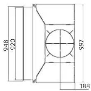

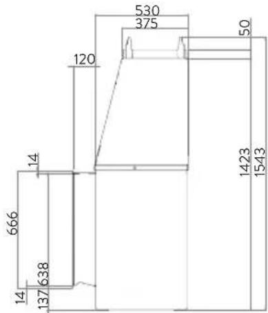
| EK950 Specifications | |
| Appliance Dimensions(mm): 977W x 1543H x 655D | |
| Appliance Weight(kg): 300 | |
| Concrete or Concrete Block Structure | |
| Minimum Cavity Dimensions without 140mm concrete(mm): 1077W x 835D | |
| Minimum Cavity Dimensions with 140mm concrete(mm): 1357W x 1050D | |
| Timber or Combustible Structure | |
| Minimum AAC Heat Cell Dimensions(mm): | 1260W x 1700H x 896D |
| Minimum Cavity Dimensions(mm): | 1320W x 1800H x 930D |
Note: For Concrete or Concrete Block Structure Height dimension refer to section D1.
EK1250
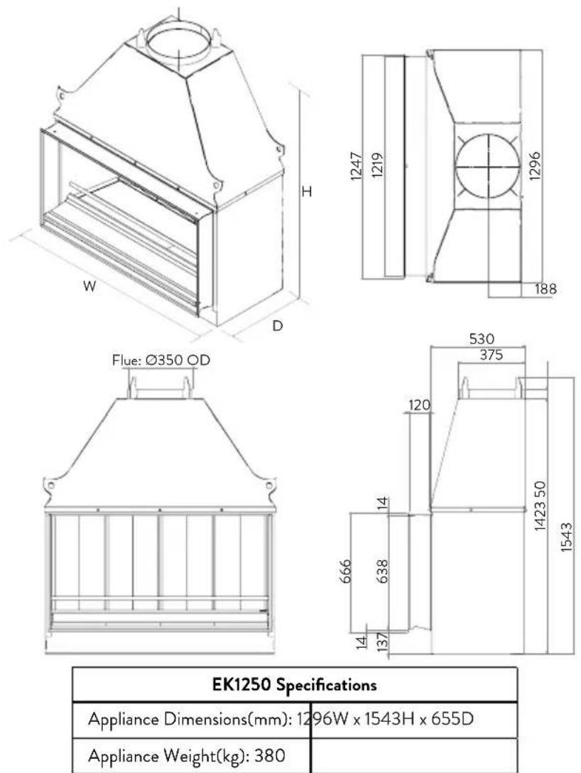
| EK1250 Specifications | |
| Appliance Dimensions(mm): 12 | 96W x 1543H x 655D |
| Appliance Weight(kg): 380 | |
| Concrete or Concrete Block Structure | |
| Minimum Cavity Dimensions without 140mm concrete(mm): 1376W x 835D | |
| Minimum Cavity Dimensions with 140mm concrete(mm): 1656W x 1050D | |
| Timber or Combustible Structure | |
| Minimum AAC Heat Cell Dimensions(mm): 1560W x 1700H x 896D | |
| Minimum Cavity Dimensions(mm): 1620W x 1800H x 930D | |
Note: For Concrete or Concrete Block Structure Height dimension refer to section D1.
Note: The EK1550 requires two flues to function properly - this is mandatory.

natural_image
Technical line drawing of a mechanical housing or enclosure with labeled dimensions H, D, and W (no text or symbols beyond labels)


| EK1550 Specifications | |
| Appliance Dimensions(mm): 15 | 96W x 1543H x 655D |
| Appliance Weight(kg): 450 | |
| Concrete or Concrete Block Structure | |
| Minimum Cavity Dimensions without 140mm concrete(mm): 1676W x 835D | |
| Minimum Cavity Dimensions with 140mm concrete(mm): 1956W x 1050D | |
| Timber or Combustible Structure | |
| Minimum AAC Heat Cell Dimensions(mm): | 1860W x 1700H x 896D |
| Minimum Cavity Dimensions(mm): | 1920W x 1800H x 930D |
Note: For Concrete or Concrete Block Structure Height dimension refer to section D1.
B
External Clearances to Combustible Surfaces
Note: The cavity structure must comply with the relevant section section “D1 Minimum Requirements of Concrete | Concrete Block Structure” on page 10 or section “E1 Minimum Requirements of the Timber | Combustible Structure” on page 13, depending on the installation method of choice.


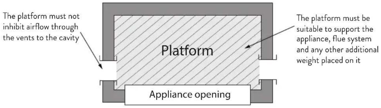
Platform Minimum Requirements
The platform must be installed at a height to satisfy the requirements listed in section "B Clearances to Combustible Surfaces" on page 8.
If the platform is to be constructed of combustible material, the platform must be insulated from the appliance. The insulation requirement depends on the installation method of choice, as follows:
If the appliance is installed into a poured concrete | concrete block structure:
The perimeter of the platform must be insulated from the appliance using either:
• Calcium silicate board (eg. 9mm Promina)
- AAC material of thickness no less than 75mm and having a minimum thermal resistance/ R-value of no less than 0.59m^2.K / W
• Concrete of a thickness no less than 140mm.
If the appliance is installed into a timber | combustible structure:
The platform must be insulated from the appliance using the required base of the AAC heat cell. See section "E3 Autoclaved Aerated Concrete (AAC) Heat Cell Assembly" on page 15 for details.
View looking down through cavity from above
D1 Minimum Requirements of Concrete | Concrete Block Structure
This appliance is designed for outdoor use ONLY.
If the appliance is installed into a concrete block or poured concrete structure, and the structure forms part of a building, then the entire appliance must be fully enclosed in concrete material of thickness 140mm or greater. Cladding over the concrete structure can consist of any heat resistant material.
When the appliance is installed in a remote, freestanding structure that is not attached to or encompassed within the envelope of the building and is at least 2000mm from any combustible material in any direction, then the enclosure may be constructed from any heat resistant material. If any combustible material is within 2000mm of the fire in any direction, then the enclosure must comply with the concrete structure specified below.
Appliance Minimum Clearances for 140mm thick Concrete Structure
Note: If installing into a heat resistant material other than concrete, or if concrete thickness is less than 140mm- minimum clearance of 2000mm to any heat sensitive material applies.

Venting Minimum Requirements for Concrete Structure
The air vent(s) can be any size or shape, provided that the total combined open surface area is at least 28000 mm^2 (eg. 2x 75mm dia vents).
Vents are necessary in the structure, not higher than 300mm above the base of the fire. Vents must take air from outside. Venting air exits the structure through the flashing cone (supplied in Escea flue kit).
Note: The EK1250 |EK950 are shown as an example; the EK1550 requires two flues.

D2 Sealing Requirements
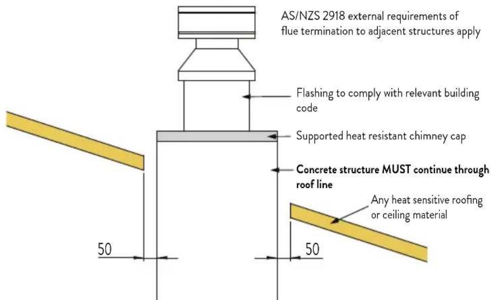
All joints in the flue system and between the gather | chassis should be sealed with a suitable high temperature fire cement sealant | cement that is able to operate at temperatures greater than 500°C.
D3 Concrete | Concrete Block Structure Flue System Installation
Flue Specifications
Note: The EK1550 will require two of each item shown below (two flue terminals, two cones, etc.). The EK1250 and EK950 require one of each item shown below.

NOTE: THE APPLIANCE & FLUE SYSTEM SHALL BE INSTALLED IN ACCORDANCE WITH AS/NZS 2918 AND THESE SPECIFICATIONS.
Flue Installation- Order of Operations
- Install first length of flue, crimp down to fit into firebox spigot
- Install first length of liner, crimp up. Liner fits onto tabs welded to firebox gather
- Repeat steps 1 and 2 with remaining flue(s) and liner(s)
- Complete flashing of structure
- Attach spider to final length of flue, such that it spaces off liners appropriately
- Fit flashing cone
- Fit cowl
Note: repeat the above process for the EK 1550 (as it has two flue pipes)
E
Timber | Combustible Structure Installation
E1 Minimum Requirements of the Timber | Combustible Structure
This appliance is designed for outdoor use ONLY.
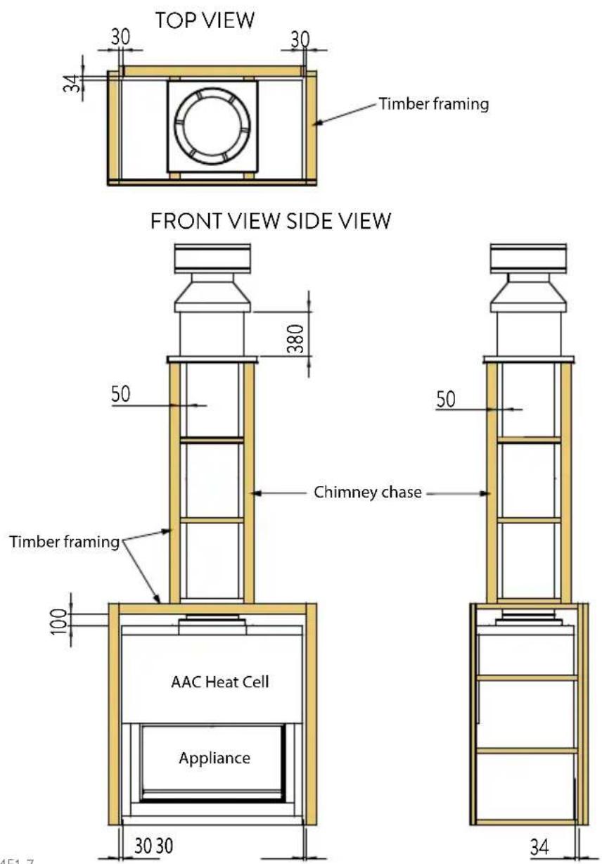
If installing into a timber/combustible structure, and the appliance forms part of a building or is part of a freestanding structure, the following minimum clearances to combustible materials must be adhered to. Furthermore, the appliance MUST be installed with an Autoclaved Aerated Concrete (AAC) heat cell consisting of panels no less than 75mm thick and having a thermal resistance/ R-value of no less than 0.59m ^2 .K/W. The ‘heat cell dropbox’ must be installed with the heat cell to comply. For minimum requirements of the heat cell see “Autoclaved Aerated Concrete (AAC) Heat Cell Assembly” on page 15.
Any cladding over the front of the structure (not including the chimney chase structure) must consist of a heat resistant material. Cladding over any other surface of the structure can consist of a combustible material (eg. plywood).
Appliance Minimum Clearances for Timber | Combustible Structure
Venting Minimum Requirements for Timber | Combustible Structure
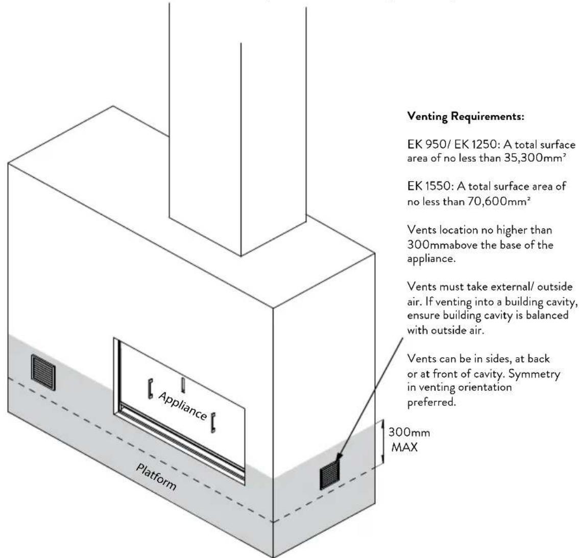
The air vent(s) can be any size or shape, provided that the total combined open surface area is at least 35,300 mm ^2 (eg. 2x 150mm dia vents).
For the EK 1550:
The air vent(s) can be any size or shape, provided that the total combined open surface area is at least 70,600 mm ^2 (eg. 4x 150mm dia vents)
Vents are necessary in the structure, not higher than 300mm above the base of the fire. Vents must take air from outside. Venting air exits through the flashing cone (supplied in Escea flue kit).
Note: The EK1250/EK950 are shown as an example; the EK1550 requires two flues.
E2 Sealing Requirement
All joints in the flue system and between the gather / chassis should be sealed with a suitable high temperature fire cement sealant / cement that is able to operate at temperatures greater than 500°C.
Care should be taken to ensure that the cavity is weatherproof.
E3 Autoclaved Aerated Concrete (AAC) Heat Cell Assembly
Minimum Requirements of the Heat Cell
The AAC heat cell MUST be constructed around the appliance if installing into a timber/ combustible structure. AAC panels MUST be at least 75mm thick and must gave a thermal resistance/ R-value of no less than 0.59m ^2 .K/W. The base of the heat cell must be constructed to the minimum dimensions prescribed to insulate the platform from the appliance. The ‘heat cell dropbox’ (supplied separately) MUST be installed with the heat cell to comply.
There should be a recess from the front of the heat cell to the front of the fire of no less than 35mm.
For the EK 950 and EK 1250, vents should be cut at the base of the heat cell, either in the sides or back panel, with an area of no less than 24,000mm^2 . For the EK 1550, the venting area must be no less than 48,000mm^2 . Note: the venting requirement for the heat cell is different from the structure venting requirements.
Note: Heat cell assemblies in this manual represent the minimum dimensions and are a guide only. The models have a 35mm recess to the front of the fire.
Heat Cell Construction Recommendations
Heat cell panels should be screwed together and bonded with a certified mortar (recommended by manufacturer) to ensure a tight seal.
The models shown in this document have a 5mm clearance from the AAC material to the firebox front flange, which should be altered depending on the chosen finishing method for the heat cell. Follow manufacturer's recommendations regarding finishing of the AAC material.
Note: To prevent the heat cell from cracking, it is recommended to light a few small fires first to dry out the AAC material.
EK 950 Heat Cell Dimensions


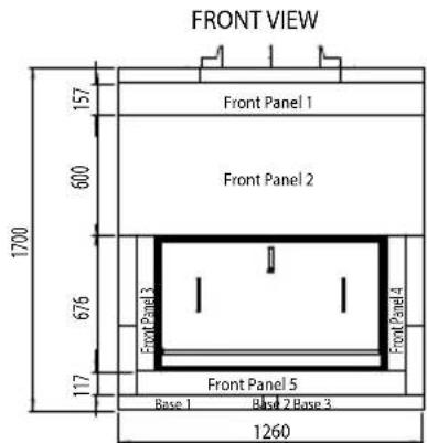

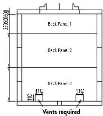
EK 1250 Heat Cell Dimensions

1x heat cell dropbox required with EK 1250 AAC heat cell
EK 1550 Heat Cell Dimensions


EK 950 Heat Cell Cut Pattern
| Top 1340 x 896 | Top 4340 x 896 |
| Base 1600 x 896 | Base 3600 x 896 | Base 260 x 896 |
| Back 2600 x 1110 | |
| Front 5 - 117 x 1110 | |
| Back 3 - 350 x 1110 |
| Back 1600 x 1110 | Front 2600 x 1260 | Top 2580 x 210Top 3580 x 100 |
| Side 2600 x 896 | Side 5600 x 896 | Side 3600 x 821 |
| Side 1350 x 896 | Side 4350 x 896 | Side 6600 x 821 | |
| Front 1 - 157 x 1260 | Front 3 - 76 x 676Front 4 - 76 x 676 | ||
Panels shown are 600mm x 3000mm x 75mm
EK 1250 Heat Cell Cut Pattern
| Top 3580 x 100 | |||
| Top 1490 x 896 | Top 4350 x 896 | ||
| Top 2580 x 210 | |||
| Base 1600 x 896 | Base 3600 x 896 | |
| Base 2360 x 896 |
| Back 2600 x 1410 | |
| Front 5 - 117 x 1410 | |
| Back 1350 x 1410 |
| Back 3600 x 1410 | Front 2600 x 1560 |
| Side 2600 x 896 | Side 5600 x 896 | Side 3600 x 821 |
| Side 1350 x 896 | Side 4350 x 896 | Side 6600 x 821 | |
| Front 1 - 157 x 1560 | |||
| Front 3 - 76 x 676 | Front 4 - 76 x 676 | ||
Panels shown are 600mm x 3000mm x 75mm
EK 1550 Heat Cell Cut Pattern
| Front 2600 x 1860 |
| Top 1490 x 896 | Front 5 - 117 x 1710 |
| Back 3350 x 1710 | |
| Base 1600 x 896 | Base 2600 x 896 | |
| Top 4 - 130 x 896 | ||
| Base 3 | ||
| 60x 896 |
| Back 2600 x 1710 | Base 4600 x 896 | Top 2580 x 210Top 3580 x 100 |
| Back 1600 x 1710 | Top 7490 x 896 |
| Side 2600 x 896 | Side 5600 x 896 | Side 3600 x 821 | Top 5580 x 280 | Top 6580 x 100 |
| Side 1350 x 896 | Side 4350 x 896 | Side 6600 x 821 | |
| Front 1 - 157 x 1860 | |||
| Front 3 - 76 x 676 | Front 4 - 76 x 676 | |||
Panels shown are 600mm x 3000mm x 75mm
E4 Timber | Combustible Structure Flue System Installation
Flue Specifications
Note: The EK1550 will require two of each item shown below (two flue terminals, two cones, etc.). The EK1250 and EK950 require one of each item shown below.

NOTE: THE APPLIANCE & FLUE SYSTEM SHALL BE INSTALLED IN ACCORDANCE WITH AS/NZS 2918 AND THESE SPECIFICATIONS
Flue Installation-Order of Operations
- Place bottom 350 spacer on first length of flue, at height such that the heat cell dropbox will rest on the spacer.
- Lift heat cell dropbox over flue onto bottom spacer.
- Install first length of flue together with spacer and dropbox. Install flue crimp down to fit into spigot on firebox gather. Dropbox should fit into square hole at top of heat cell.
- Place 350-400 spacer onto first length of flue, near top.
- Install first length of inner liner, crimp up. Liner fits to dropbox, on the inside of the dropbox's upright tabs.
- Place 400-450 spacer onto first inner liner, near top.
- Install outer liner, crimp down. Outer liner sits on the dropbox's upright tabs.
- Install further lengths of flue, inner and outer liners as required.
- Complete flashing of structure.
- Attach spider to final length of flue, such that it spaces off liners appropriately.
- Fit flashing cone.
- Fit cowl.
Note: repeat the above process for the EK 1550 (as it has two flue pipes).
Timber | Combustible Structure Flashing Options
Flashing with Chase Structure

Flashing through Roof

F
Assembling and Installing the Fireplace
F1 Gather Installation
The EK Series fires are shipped with most of the interior components packaged and set inside the gather. Remove all of these components and set them aside for later.

CAUTION: Team or mechanically aided lift required for gather.
Gather Weight
EK950: 60 kg
EK1250: 80 kg
EK1550: 120 kg
Once the gather is in place, attach using the bolts, nuts, and washers provided.
F2 Securing the Base of the Appliance
Begin by removing all of the bricks from the fireplace. Remove the shaded parts below to access the securing holes. The EK1250 has been used as an example; the EK950 and EK1550 would be secured in the same manner.
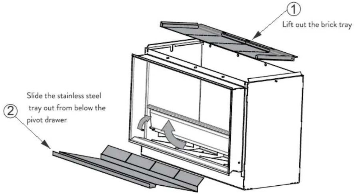
Note: Gather is not pictured
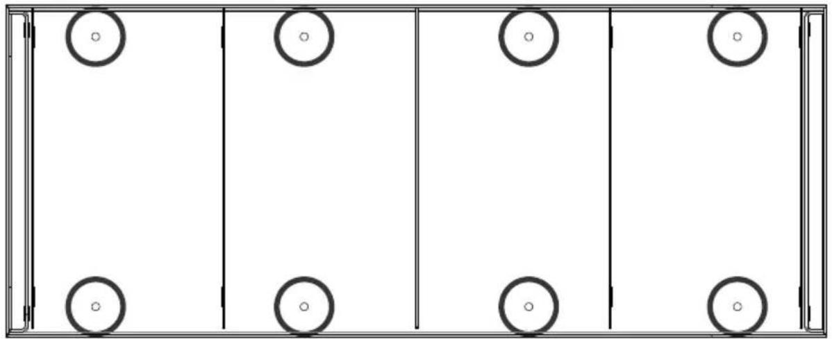
Secure the appliance base suitably using any 4 of the holes circled below.
natural_image
Pure diagram of a rectangular frame with six circular holes, no text or symbols presentF3 Assembling the Fireplace
The EK1250 has been used as an example in the images below. The EK950 will have one fewer panel and racking strip; the EK1550 will have one more panel and racking strip. Unwrap all of the provided parts and remove the plastic film from the stainless steel tray (1).

Note: Gather & pivot drawer not pictured

Note: For the EK950 there is no end spacer - cut bricks are supplied
F4 Attaching and Removing the Pivot Drawer
The stainless steel pivot drawer at the front of the fire, shaded grey in the diagram below, can be attached and removed from the fire for cleaning or repair. To remove the drawer, follow the instructions below.
NOTE: Remove the protective plastic film on the pivot drawer prior to burning the fire.
natural_image
Technical line drawing of a mechanical housing or enclosure with internal components and mounting brackets (no text or symbols)
natural_image
Close-up of a black industrial cabinet with transparent plastic panels and a horizontal light fixture (no visible text or symbols)The drawer is centrally located by a spring on both the right and left hand sides.
Flip the drawer up and remove the screw holding the pin in place.

natural_image
Close-up of a metallic pipe fitting attached to a wall, showing internal components and a cylindrical shaft (no text or symbols visible)
natural_image
Close-up of a finger pressing a metallic mechanical component with bolts (no text or symbols visible)With the screw removed, pull on the pin to remove it. Place one hand beneath the spring to catch it as the pin is removed. Repeat this on the opposite side to remove the other pin. The drawer will now slide out.
To replace the drawer, reverse the above steps.
F5 Using the Weather Cover (Optional Accessory)
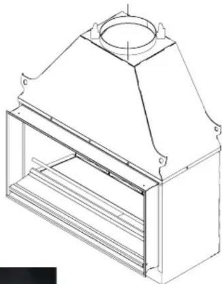
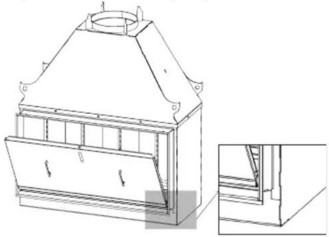
The weather cover (shown below) provides protection from the elements for the interior of the firebox. It is an optional accessory that can be purchased from your local Escea dealer. Ensure that the firebox is cool prior to fitting the weather cover.

To install the weather cover, position the hooks at the bottom of the weather cover on the pins located on either side of the pivot drawer of the fireplace, as shown below.
natural_image
Technical line drawing of a traditional Chinese industrial furnace or boiler unit with a side-view inset showing internal structure (no text or symbols)With the bottom hooks in place, rotate the weather cover up until it slides into the top, as shown below. Use the latch to ensure that the weather cover is locked into place.

natural_image
Technical line drawing of a mechanical cabinet or enclosure with a conical top and two internal doors (no text or symbols)G1 Fuel Selection
For optimal wood burning, use firewood with a moisture content of less than 20%.
G2 Starting the Fire
If you are starting your fire for the purpose of cooking, then please proceed to section "H Cooking Guide" on page 28.
To start the fire, stack kindling so that it leans against the back panels, allowing sufficient airflow between pieces. The use of fire-starters is recommended. Continue adding kindling until you have established an ember bed across the entire width of the fire. Use the provided fire poker to arrange the embers across the fire bed.

natural_image
Architectural cross-section diagram showing structural layers and material distribution (no text or symbols)DO NOT load wood higher than 33% the height of the firebox
For an optimal lighting time, stack kindling vertically against the back of the firebox and use fire-starters to ignite the wood in a timely manner.
Note: Expansion/contraction noises during heating up and cooling down cycles are normal and to be expected.
G3 Loading the Fire
Once an ember bed has been established, continue loading larger pieces of firewood onto the fire until the desired temperature or look has been reached. Ensure that all pieces of firewood do not protrude past the bottom stainless steel bar on the fireplace.
Do not load wood higher than 1/3 (33%) of the height of the firebox.
G4 Extinguishing the Fire
Once you have finished with burning the fire, remove all embers and remaining wood pieces from the fire and place them in a fireproof pail. Soak them well. Store them for a minimum of 5 days prior to disposing of them safely.
Supervise the fire until all logs and embers have been removed.
Note: The firebox will remain warm for several hours after the embers have been removed. Use caution when touching any parts of the firebox (i.e. the bricks, pivot drawer, or back panels) and supervise small children until the firebox has cooled completely.

Cooking Guide
H1 Cast Iron Instructions
All cast iron parts lock into the grill frames provided with the appliance. Ensure that they are securely set prior to cooking.
The cast iron parts supplied are coated in a vitreous enamel. In the event of decay or chipping, the cast iron can be seasoned by rubbing a thin layer of oil on the cast iron and heating the surface.
Seasoning will protect the surface from rusting and reduce the likelihood of food sticking to the surface.
H2 Storage
The EK range of fireplaces is designed to allow storage of cooking implements within the fire. To access the storage area, lift the pivot drawer as shown in the diagram below.

H3 Optimal Ember Generation
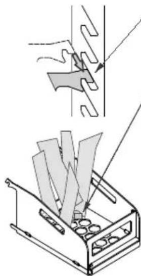
The most efficient way to cook on a wood fire is over a consistent bed of embers. To achieve this, an ember generation box has been provided. To begin, affix the ember generator to any of the racking sets on the back of the fireplace and follow the instructions below.
natural_image
Technical illustration of a mechanical device with cutaway view showing internal components (no text or symbols)Step 1: Affix the ember generator to the back of the firebox
Step 2: Vertically stack kindling
Step 3: Place and ignite fire-starters on the base of the ember generator
Step 4: Place more logs, & if necessary, more fire-starters
Step 5: For optimal ember generation, keep the ember generator fueled with pieces of hardwood that will roughly fit inside the opening of a drinking mug (80mm cross-section).
Note: Other wood or larger wood diameters can be used but will not perform as well. Softwood embers will burn out more quickly and larger diameter wood will take longer to produce embers.
Continue to load the ember generator with wood. Use the fire poker provided to get embers to fall through the grate on the bottom of the ember generator.
H4 Cooking on the Fire
Begin by positioning the desired number of cooking plates at the desired height in the fire. For a warmer grill, position the cooking grills closer to the bottom of the fire. For lower heat, position the cooking grills higher.

natural_image
Technical line drawing of a traditional heating unit with top, side, and interior panels (no text or symbols)For the slotted grill, it is best to position the fat drip tray on the front of the grill prior to cooking. The fat drip tray will collect any grease drips to provide easy cleanup. Align the hooks of the fat drip tray with the slots in the grill, then pull forward and hook the fat drip tray to the grill frame.
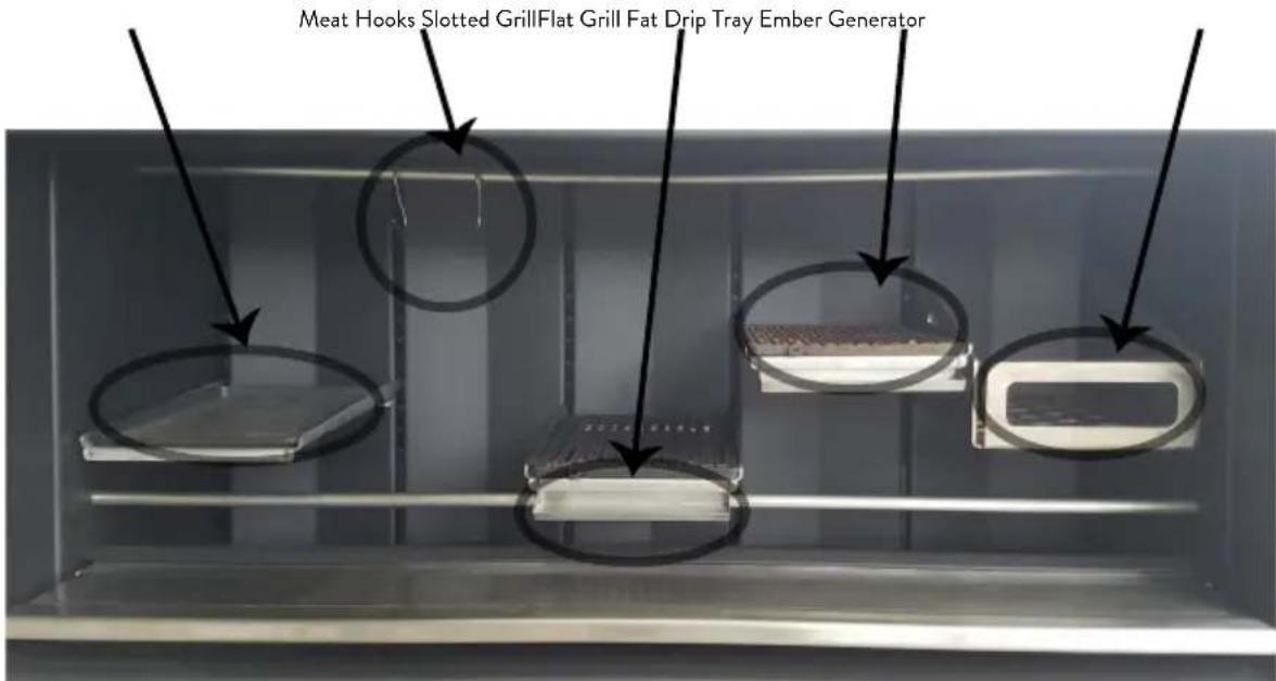
To heat the grills, use the fire poker to scrape the embers from under the ember generator to beneath the desired grill. Continue to load the ember generator so that fresh embers continue to drop through the grate. To maintain heat, continue to scrape fresh embers beneath the cooking area until cooking is complete.
The EK range also comes with meat hooks, as shown in the image above, that can be used to hang and cook large pieces of meat (for example, a whole chicken). The process is the same as with the grills; scrape embers beneath the meat hooks to cook the meat.
It is also possible to use damp wood chips (i.e. cedar, hickory, etc.) thrown directly onto the embers to provide a smoky flavour to the cooking food.
Once you have finished cooking, remove all cooking trays and the ember generator prior to using the fire for standard outdoor heating.
Use the provided gloves when handling the hot cooking trays and the ember generator. Heat will begin to transfer through the gloves after 30 seconds. It is recommended to move the hot trays within 30 seconds. It is also possible to scrape the embers away from the ember generator and cooking trays to allow them to cool; it takes approximately 20 minutes to be able to move them without the heat transferring through the gloves.
Maintenance
I1 Chimney Maintenance
The chimney must be inspected & cleaned at least once per year.
A chimney fire can permanently damage your chimney system; this damage can only be repaired by replacing the damaged component parts.
Chimney fires are not covered by the warranty.
12 Recommended Refurbishment Products Stovebright Metallic Black Spray Paint
This product may be used on all black painted surfaces and is available from your Escea dealer.
Before application, ensure any corrosion is removed by a wire brush; also ensure that the surface is clean and free of any dust.
There is no guarantee the parts can be returned to a new finish.
Autosol Metal Polish
This product may be used on any stainless steel surfaces and applied with a soft cloth.
There is no guarantee the parts can be returned to a new finish.

General Warranty Terms and Conditions
General Information
This quality manufactured product is state of the art. The materials used were meticulously selected and are constantly checked, as is our entire production process.
Setting up or installing this product requires specialised knowledge. Escea products may therefore only be installed and commissioned by specialised firms and in compliance with statutory regulations as amended.
Warranty Conditions for Escea Outdoor Wood Fires
This warranty is provided by Escea Limited (referred to in this document as Escea). The warranty applies from the date of purchase from or through an authorised Escea dealer.
Nature of Warranty
Subject to the exclusions in section 2 & 3, Escea may undertake to put right any defects in the Escea Outdoor Wood Fire products supplied by Escea for the periods specified below:
| Parts Parts and Labour Warranty | |
| Basic firebox**: the steel body of the product only | 5 years* |
| Any removable part, including: top combustion panel, back panels, cooking plates, ember generator, pivot drawer, operation devices such as handles, adjustment levers | 2 year* |
* From date of purchase
** Failure is considered a physical crack or hole that stops the fire functioning as it is designed to.
Escea must pre-authorise all warranty work.
The benefits provided under this warranty are in addition to the consumer guarantees and any other statutory rights you may have under the consumer law and/or other applicable laws.
Warranty Exclusions
This warranty does not apply and will be void where:
The Escea Outdoor Wood Fire is not installed in accordance with AS/NZS 2918:2001 and any building code and consent (if required).
The Escea Outdoor Wood Fire has not been installed or operated in accordance to the Escea Outdoor Wood Fire installation manual, in particular, defects, malfunctions or failures caused by incorrect installation, normal wear and tear, misuse, neglect, lack of proper and regular maintenance, accidental damage, any other alteration, or failure to follow operating instructions in the installation manual or any misuse that causes an overfired situation resulting in heat damage.
The use of products, including flue systems, that are not specified in accordance with the installation manual.
Repairs or modifications by persons not authorised by Escea, use of parts not supplied by Escea, or damage or other events which have occurred since the product left the control of Escea.
Any scratches, dints, finger print marks, and melted items that occurred after the arrival of the product to the Escea Dealer.
Discolouration of the enamel, galvanized surfaces, or glass caused by soiling by soot or built-in residues of burnt materials as well as visibly changed colour or other aspects due to thermal stress or overloading.
Changes in the interior / exterior surfaces of the house, fire, or flue (e.g. any staining or soot / smoke damage, cracking, discoloration or degradation of surfaces caused by thermal stress or overloading).
Damage caused by abnormally corrosive environments (e.g. sea salt corrosion).
Escea wood fires are coated with high temperature paint that may show signs of surface rust if exposed to moisture for an extended period of time. Any repair and replacements of parts that are subject to normal wear and tear expected with any outdoor fire product. Any rust damage discolouration or corrosion in any part of the fire over life of the fire is not covered by warranty.
Damage caused by water affecting the Escea outdoor wood fire.
Operation of the Escea outdoor wood fire without its back panels (if applicable).
Damage caused by chimney fires.
This warranty does not cover paint blemishes or imperfections because of the uneven nature of high temperature paint. A spray can of touch up paint is available at a local paint merchant.
Subject to any statutory provisions to the contrary, at Escea's discretion, Escea's liability in respect of EK Series products that are found to have manufacturing defects will be limited to refunding, repairing, or replacing the defective products. The reinstatement and replacement of any affected outside wall, ceiling, or floor coverings, coatings, or claddings are not covered by warranty. Escea does not accept liability for consequential damage or any incidental expenses resulting directly or indirectly from any defect or breach of warranty, claims for damage to building or any other consequential loss.
Other Escea Outdoor Wood Fire Warranty Conditions
No dealer, distributor, or similar person has the authority to warrant Escea products beyond the terms contained in this warranty.
This warranty is automatically voided if the appliance's serial number has been removed or altered in anyway.
Any differences in fireplace appearance from Escea promotional images that is due to printing limitations, environmental factors, or wood variations are not a warranty issue.
Where you make a claim under this warranty, an authorised repairer may need to attend your premises to inspect the Escea product. Escea may charge you a service call fee if a repairer will be required to travel more than 30 km from the nearest service centre to your location. You can obtain details on the location of service centres and service call fees by visiting the Escea website or calling the customer care line below.
Warranty Claims
If you make a valid claim under warranty and none of the exclusions set out in section 2 and 3 apply, Escea will, at Escea's election either:
Repair the relevant part of the Escea product; or
Replace the relevant part of the Escea product with a product of identical specification (or where the product is superseded or no longer in stock, with a product of as close a specification as possible).
How to Make a Warranty Claim
To make a valid claim under this warranty, you must:
- Lodge the claim through the dealer who supplied the fire, as soon as you first become aware of the breakdown. The Escea Dealer will then follow Escea's warranty claim process.
- Provide the Escea product serial number.
- Provide reasonable proof of purchase for the Escea product.
- If required, provide access to the premises at which the Escea product is located (so it can be inspected).
| Regions Escea Distributors Filing a Claim | ||
| Australia Escea Australia | PTY Ltd.P.O. Box 176Pennant Hills, 1715, Sydney, NSWAU: 1800 460 832 or WA: 1800 730 140www.escea.com.au | Visit the distributor website or call distributor directly. |
| New Zealand Escea Ltd. | 17 Carnforth StreetDunedin, 9018, New Zealand0800 17 3000www.escea.com | Contact the dealer you purchased the fire from |
Contact the dealer you purchased the fire from to file a claim.
This document contains technical data subject to change without notice.
- Installation Instructions and User Guide
- WARNING
- Warranty Repair and Annual Servicing
- A Installation Process and Product Details 5
- B External Clearances to Combustible Surfaces 8
- C Platform Minimum Requirements 9
- D Concrete/ Block Structure Installation 10
- E Timber/ Combustible Structure Installation 13
- F Assembling and Installing the Fireplace 22
- G Burning Guide 27
- H Cooking Guide 28
- I Maintenance 31
- J General Warranty Terms and Conditions 32
- A1 Product Description
- A2 Product Dimensions
- B
- External Clearances to Combustible Surfaces
- Platform Minimum Requirements
- If the appliance is installed into a poured concrete | concrete block structure:
- If the appliance is installed into a timber | combustible structure:
- D1 Minimum Requirements of Concrete | Concrete Block Structure
- Appliance Minimum Clearances for 140mm thick Concrete Structure
- Venting Minimum Requirements for Concrete Structure
- D2 Sealing Requirements
- D3 Concrete | Concrete Block Structure Flue System Installation
- Flue Specifications
- Flue Installation- Order of Operations
- E
- Timber | Combustible Structure Installation
- E1 Minimum Requirements of the Timber | Combustible Structure
- Venting Minimum Requirements for Timber | Combustible Structure
- For the EK 1550:
- E2 Sealing Requirement
- E3 Autoclaved Aerated Concrete (AAC) Heat Cell Assembly
- Minimum Requirements of the Heat Cell
- Heat Cell Construction Recommendations
- EK 1250 Heat Cell Cut Pattern
- E4 Timber | Combustible Structure Flue System Installation
- Flue Installation-Order of Operations
- Timber | Combustible Structure Flashing Options
- F
- Assembling and Installing the Fireplace
- F1 Gather Installation
- F2 Securing the Base of the Appliance
- F3 Assembling the Fireplace
- F4 Attaching and Removing the Pivot Drawer
- F5 Using the Weather Cover (Optional Accessory)
- G1 Fuel Selection
- G2 Starting the Fire
- G3 Loading the Fire
- G4 Extinguishing the Fire
- Cooking Guide
- H1 Cast Iron Instructions
- H2 Storage
- H3 Optimal Ember Generation
- H4 Cooking on the Fire
- Maintenance
- I1 Chimney Maintenance
- Recommended Refurbishment Products Stovebright Metallic Black Spray Paint
- Autosol Metal Polish
- General Warranty Terms and Conditions
- General Information
- Warranty Conditions for Escea Outdoor Wood Fires
- Nature of Warranty
- Warranty Exclusions
- Other Escea Outdoor Wood Fire Warranty Conditions
- Warranty Claims
- How to Make a Warranty Claim
Brand : Escea
Model : EK1550
Category : Heating