
HWD-2105 - Water dispenser Fetco - Free user manual and instructions
Find the device manual for free HWD-2105 Fetco in PDF.


| Type | Hot Water Dispenser (Digital) |
| Brand | Fetco |
| Model | HWD-2105 |
| Height | 24.5 in (62 cm) |
| Width | 9 in (23 cm) |
| Depth | 18.5 in (47 cm) |
| Weight (empty) | 24 lbs (10.9 kg) |
| Weight (filled) | 49 lbs (22 kg) |
| Water Tank Capacity | 3.2 gallons (12 liters) |
| Temperature Range (Selectable) | 158°F to 204°F (70°C to 96°C) |
| Maximum Single Dispense | 24 oz (700 cc) in 15 seconds |
| Electrical Configurations | 120V 1.44kW/12A, 120V 2.1kW/17.5A, 200-240V 3.2kW/11.2-13.4A, 230V 2.9kW/12.8A |
| Water Pressure | 40-75 psig (276-517 kPa) |
| Minimum Flow Rate | 1.5 gpm (5.7 lpm) |
| Water Connection | 1/4 inch male flare fitting |
| Control Technology | ^tf_c Touch Function Selector with digital display |
| Display | Digital screen with temperature and status icons |
| Drip Tray | Removable with built-in float indicator |
| Daily Maintenance | Check and empty drip tray |
| Quarterly Maintenance | Inspect for leaks; de-lime tank and probes if needed |
| Safety Features | Auto lockout when tank depleted, error code diagnostics, high-temp warning |
| Installation Requirement | Under-sink or countertop; requires shut-off valve, backflow prevention, water filter recommended |
| Warranty | Refer to separate warranty document (not included in manual) |
Frequently Asked Questions - HWD-2105 Fetco
User questions about HWD-2105 Fetco
0 question about this device. Answer the ones you know or ask your own.
Ask a new question about this device
Download the instructions for your Water dispenser in PDF format for free! Find your manual HWD-2105 - Fetco and take your electronic device back in hand. On this page are published all the documents necessary for the use of your device. HWD-2105 by Fetco.
USER MANUAL HWD-2105 Fetco
^t_f Touch Function Selector Technology
HWD-2105 Hot Water Dispenser
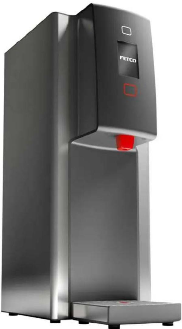
natural_image
Exterior view of a modern stainless steel water dispenser with 'FETCO' branding and red indicator light (no readable text beyond branding)NOTICE TO INSTALLER: Please leave this book with the machine.
Temperature On Demand US design patent applied for. Other Temperature On Demand US patents applied for. FETCO®, is a trademark of Food Equipment Technologies Company.
FETCO® HWD-2105 Hot Water Dispenser
Contact Information
FETCO®
Food Equipment Technologies Company
600 Rose Road
Lake Zurich • IL • 60047-0429 • USA
Internet: www.fetco.com
Phone: (800) 338-2699 (US & Canada)
(847) 719-3000
Fax: (847) 719-3001
Email: sales@fetco.com
techsupport@fetco.com
Description & Features
Water temperature selectable to 158°-204°F/70-96°C English and Metric temperature ranges selectable
Maximum single dispense is 24ounces/700cc in 15 seconds maximum dispense time
Non-Temperature on Demand and Temperature on Demand (TOD) configurations is available as separate equipment.
Specifications
Standard Electrical Configurations-DOMESTIC & CANADA
| Configuration Code | Heater Configuration | Voltage | Phase | Wires | NEMA Plug | KW | Maximum Amp Draw | Gallons/Hour |
| H210511 | 1 X 1.44 kW | 120 | 1 | 2+G | NEMA 5-15P | 1.5 | 12.0 | 4.0 gallon*/15 liter |
| H210521 | 1 X 2.1 kW | 120 | 1 | 2+G | NEMA 5-20P | 2.2 | 17.5 | 5.7 gallon*/22 liter |
Standard Electrical Configurations-DOMESTIC & SPECIALTY
| H210531 | 1 X 3.2 kW | 200-240 | 1 | 2+G | NEMA 6-15P | 2.3-3.3 | 11.2-13.4 | 6-8.7gallon*/22.7-33 liter |
| Electrical Configurations- EXPORT & CANADA | ||||||||
| H210541 | 1 X 3.2 kW | 230 | 1 | 2+G | Cord Only† | 2.9 | 12.8 | 7.8 gallon*/29.5 liter |
Temperature range is selectable from 158°-207°F/70-97°C based on 207°F/97°C hot water tank temperature.
*Flow rate based on 65-70°F 18-21°C water mains supply temperature at lowest possible power supply current.
Selectable English and Metric temperature units. † For EXPORT, Cord without plug will be attached
Single touch pad selectable hot water dispense temperature.
Pressure: 40-75 psig, (276-517kPa)
Water Requirements: Minimum Flow Rate: 1½gpm (5.7lpm)
Water connection inlet: 14 inch male flare fitting
Power Plug Configurations
Weights and Capacities
| Dispenser Model | Weight (empty) | Water tank Capacity | Weight (filled) | Height Inches/cm | Wide Inches/cm | Deep Inches/cm |
| Hot Water Dispenser HWD-2105 | 24 lbs/10.9kg | 3.2 gallon/12 liter | 49 lbs/22kg | 24 1/2 in/62 cm | 9 in/23 cm | 18 1/2 in/47 cm |
| NOTE: Temperature accuracy of dispensed hot water may vary up to 3 1⁄2 % of displayed temperature selection. Factors affecting accuracy include quantity of hot water dispensed, ambient air temperature, distance of container from hot water faucet (pouring over longer distance causes more cooling) | ||||||
NEW TECHNOLOGICAL FEATURES
The FETCO hot water dispenser uses new ^tf_c Touch Function Selector Technology to operate the hot water dispenser.
The ^t f_c Touch Function Selector buttons (above and below display screen) alternately dim and brighten when selection is not active.
Dispensing and Feature Selections activate when touched. The front panel is clean and uncluttered.
Programming, display and error codes are interactive and more intuitive.
Float indicator is built into drip tray to help simplify maintenance and cleaning.
NOTE:
The HWD-2105 Digital Hot Water Dispenser cannot be modified into a HWD-2105 TOD Temperature on Demand Hot Water Dispenser
Dimensions & Utility Connections
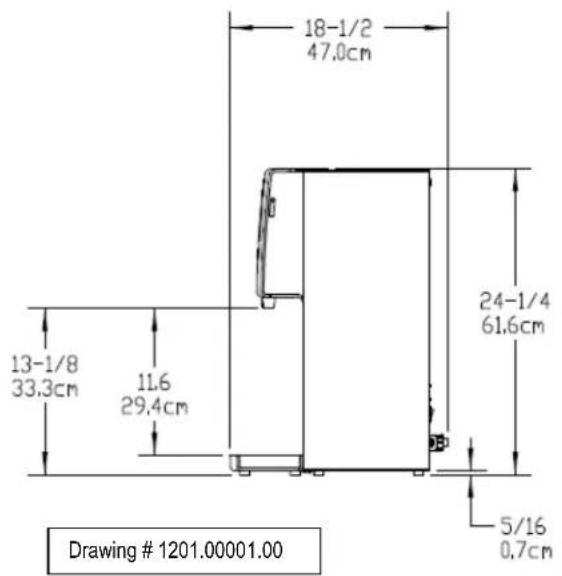
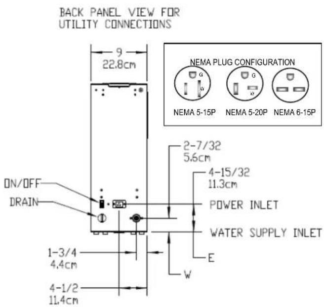
Water inlet fitting: 14 inch male flare fitting
Installation
The installation must comply with applicable federal, state, and local codes having jurisdiction at your location. Utilize only qualified beverage equipment service technicians for installation.
A Service Company Directory may be found on our website, http://www.fetco.com.
Setup
- Before placing the unit, verify that it will fit in the space intended for it, and that the counter or table will support the weight of the HWD-2105 when filled.
- When the unit is in position, use a bubble level to level it front to back and side to side by adjusting the legs.
Water Connection
- Water inlet is a 14 inch male flare fitting.
- Install a shut off valve near the unit to facilitate service.
- Install a backflow prevention device. A spring loaded double check valve such as a WATTS® SD-2 or SD-3, two models accepted by most zoning authorities. The check valve should be as close to the water supply inlet as possible.
- An inline water filter is highly recommended. It should be installed after the water shutoff valve and in a position to facilitate filter replacement.
- Flush the water supply line and filter before connecting it to the unit.
- Verify that the water line provides at least 112 gpm (5.7lpm), and that the water pressure is between 40-75 psig (276-517kPa).
Electrical Connection
- Check serial number plate for the maximum wattage and verify that the actual voltage at the electrical outlet is compatible with the unit's specifications.
- Plug unit in. Note that the plug is NEMA 5-15P or NEMA 5-20P (domestic).
- The temperature and water tank fill level are pre-set at the factory and there is no need to turn off the heater during the installation process. The heating process will start automatically when the tank is filled enough to cover the heating element

Warning: Legs are to be adjusted only to level the unit. Do not extend them higher than necessary
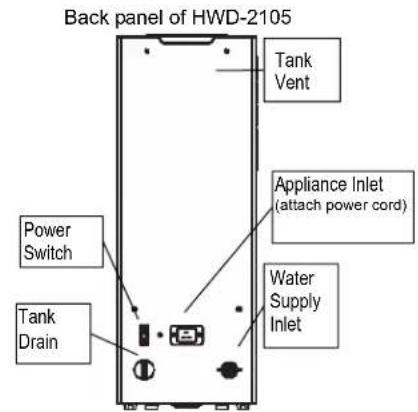

Warning:
To prevent electrical shock, this unit must be properly grounded.
Final Setup-Fill and Initial Heating
- Turn on the incoming water supply line and inspect both inside and outside of the unit for leaks in all fittings and tubes.
- Plug the unit into the appropriate electrical outlet.
- Turn on the unit's main power switch (located on the back). Screen one-the FETCO Home Screen will display.
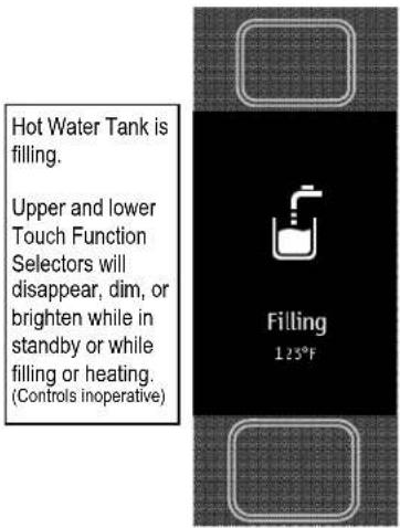
- Within 6 seconds, the water tank will begin filling until tank probe senses water Screen two, the "FILLING" will display.
- Water will cover heating element or when tank water is heating from cold, Screen three-the "HEATING" Screen will display. The upper and lower "Touch Function Selector" will not light.
- After the water has reached the set temperature, the lower "Touch Function Selector" will light red color to signal READY
(The touch selector buttons will alternately dim and brighten when selection is not active)
- The display will read the four temperature settings as the tank temperature rises. More detailed operation information follows
- The upper "Touch Function Selector" will light when the pre-set is ready
- Re-inspect for leaks.
Operating Instructions
- Turn the main power switch on.
- Touch the upper "Touch Function Selector", tapping finger to scroll to select
- When a temperature is enlarged and brightened - that temperature is available. Touch the lower red selector to dispense hot water.
- Maximum continuous "ON" is fifteen seconds in a single activating touch
- Maximum dispense is approximately 1quart/1 liter.
Approximately three 1quart/1 liter batches may be dispensed in succession.
- Unit returns to inactive "Enabled Screen" if no water is dispensed in 3 seconds
- Steam and condensation from the water tank is released into the vent whenever the unit is on. Access the vent barbed fitting located on the upper back to run gravity drain. For venting to a drain, tubing requirement is 14 " I.D. (To prevent vacuum backflow, do not place discharge end of vent drain tube into drain sump)
Operator Training
Review the operating procedures with everyone who will be using the unit.
Pay particular attention to the following areas:
- How to change temperature settings (See page 7) & dispensing water
- Scrolling and selecting temperatures and operating the hot water faucet. Pay particular attention to the safety warnings. (See page 6 & 7)
- Refer to cleaning procedures and drip tray, listed on the following page.
- Show the location of the on/off switch, water shut off valve and the utility power supply circuit breaker for the unit. (See page 3)
The three primary screens for HWD-2105 start up
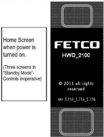
Above-Screen One-FETCO Home Screen Below-Screen Two-HWD Status Screen
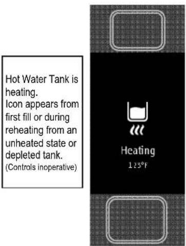
Above-Screen Three-HWD Status Screen
Operating Principles
The dispense valve assembly delivers precision temperature water at selected temperatures.
When hot water is drawn from the faucet, the fill valve pulses on and off every few seconds to replenish the tank.
By controlling the flow of incoming water, the amount of cold water entering the tank is synchronized with the rate at which the water can be heated. This ensures an uninterrupted supply of hot water.
When dispensing water at a rate that exceeds the unit's capacity to heat, the screen will show that the temperature is not available.
If hot water tank supply is depleted during high use, faucet will temporary “lockout” to allow the hot water tank to reheat for an adequate hot water supply. The “HEATING” screen will display at this time.
Cleaning & Maintenance
Daily:
- Check the drip tray and empty if necessary.
Quarterly:
- Inspect all fittings and hoses for leaks.
- Inspect inside of tank for lime deposits. De-lime tank and probes if necessary. This procedure should be performed by a qualified service technician
Notice:
- Turn off power to the HWD-2105 before any cleaning procedure, including wiping the exterior for appearance reasons. Dry the exterior, especially the face panel, before turning on power.
WARNING:
- Do not apply any type of spray cleaner on the face panel of this equipment.
- Never use any solvent based cleaner or polish on this equipment.
- Dry the face of the HWD-2105 before turning on power.
- WARNING-Do not plug-in this equipment or attempt to operate without all covers in place and all screws fastened.
Tank Drain
The water tank must be drained before maintenance procedures, and when the unit is to be relocated or shipped.
- Disconnect power to the unit.
- Move the unit near a sink or obtain a container to large enough to hold the four gallons of water from the tank.
- Remove the tank cover and allow the tank to cool to a safe temperature.
- The tank drain is located on the back of the unit. Turn the drain plug one-quarter turn in either direction.
- Pull the plug out far enough to expose the silicone tube.
- Using pliers loosen the hose clamp and move it back over the tube.
- Crimp the tube an inch or two away from the drain plug to prevent water from flowing.
- Use the other hand to pull the drain plug out of the tube.
- Release the crimped tube and allow the water to flow into the sink or container.
Control and Operational Screens
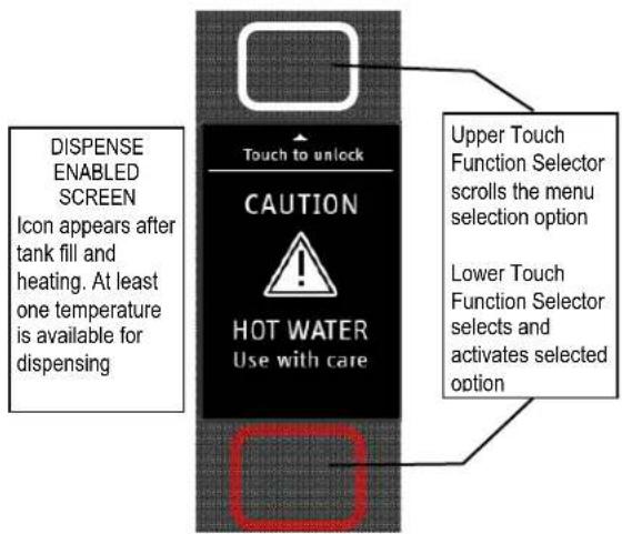
The FETCO® Hot Water Dispenser uses a digital display screen and illuminated touch pads to control the set-up and on-off water functions.
-Upper and lower pads are lighted when ready, and may alternately brighten and dim.
-Touch lower (red) pad to activate.
- "WARNING-HOT WATER" screen will light for two to three (2-3) seconds
-The upper (white) selector pad will light when selected temperature is ready
-Touch and hold lower (red) pad to dispense hot water.
-Maximum single dispense is 24ounces/700cc in 15 seconds maximum dispense time
-When dispensing an amount of water- ("DISPENSE ENABLED SCREEN") displays after five (3) seconds inactivity.
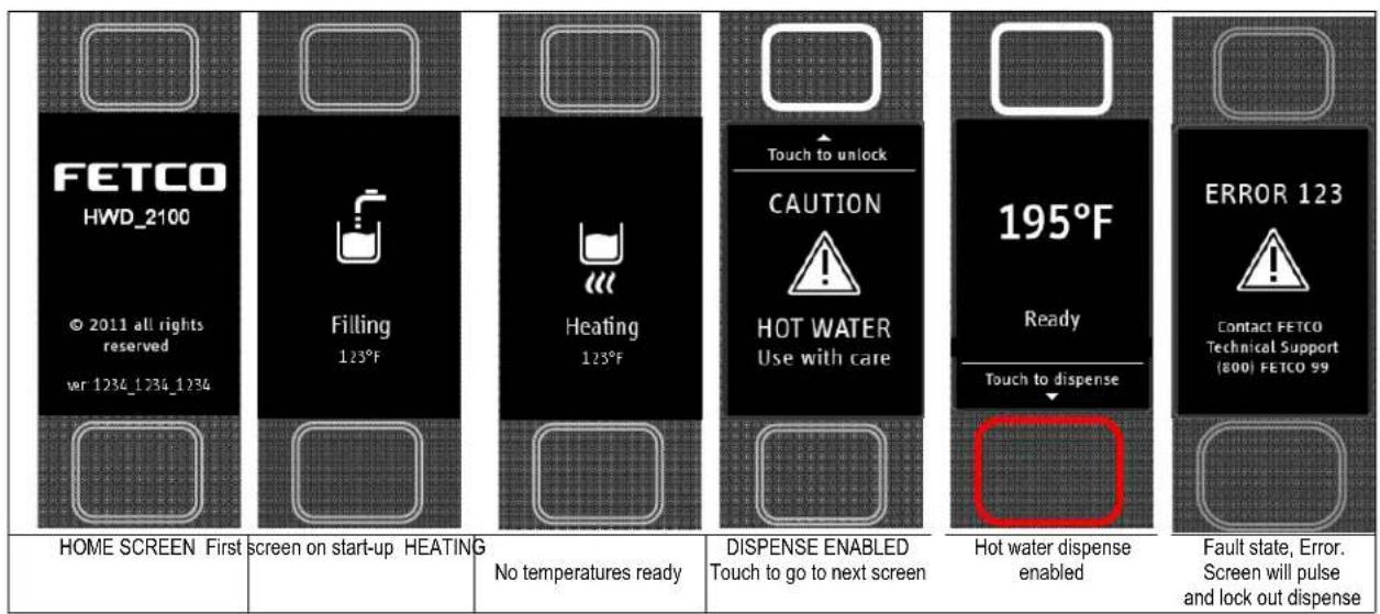
Programming and diagnostic screens
To enter Programming and Diagnostics dialog screens
Turn power switch on lower back of unit "OFF"
Turn power switch "ON" and when first screen is displayed touch lower (red) pad to activate
The First Programming screen will display. Displayed are the default settings programmed into the equipment
Touch upper "Touch Function Selector" to scroll through the programming lines.
Touch lower (red) pad to scroll through the screens and active outputs.
Setting as displayed will be saved on exit.
EXIT Programming and Diagnostics dialog by selecting EXIT and touching the lower (red) pad
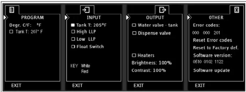
| Programming for hot water tank temperature setting (also dispense temperature) and display units (°C or °F) | Internal tank functions Verify probe readings for tank temperature, and water level.Show status of liquid level probes for tank water level. | Output TOD functions And test points.Will activate selection for 2-3 seconds. | Service technician error report for fault and software diagnostics and upgrade |
| PROGRAMMED Tank Temperature and Dispense Temperature are the same | Touch pad verification (instructions in following section) |
| Chart to correct for boiling point for altitude in tank water temperature. See INPUT Screen | ||
| Altitude (ft.) | Suggested Setting(°F) | Boiling point (°F) |
| -500 207 | 212.9 | |
| 0 207 2 | 12.0 | |
| 500 207 | 211.1 | |
| 1000 205 | 210.2 | |
| 2000 204 | 208.4 | |
| 2500 203 | 207.5 | |
| 3000 200 | 206.6 | |
| 3500 197 | 205.7 | |
| 4000 195 | 204.8 | |
| 4500 194 | 203.9 | |
| 5000 194 | 203.0 | |
| 5500 193 | 202.0 | |
| 6000 192 | 201.1 | |
| 6500 191 | 200.2 | |
| 7000 190 | 199.3 | |
| 7500 188 | 198.3 | |
| 8000 187 | 197.4 | |
| Error Code Screen | ||
| Error codes are cleared by selecting the “OTHER” screen. Scroll and press the upper control to “Reset Error Codes”. Press the lower selector to clear. | Error codes050 Shorted temperature probe - tank051 Open temperature probe - tank052 Outlet temperature sensor shorted053 Outlet temperature sensor open100 Initial fill error (not filled in 6 minutes after power up)101 Error on refill (The tank has not refilled in 1 minutes-Possibly faulty solenoid or issue with the water line)102 Unwanted fill (Possibly tank or internal leak)103 Overflow error (float switch activated)104 Lower (longer) liquid level probe fault105 Upper (shorter) liquid level probe fault200 Flat line temperature201 Heater open (heater or triac failure) | |
| Touch pad function testTests the Upper and Lower touch pads for proper sensitivity.Use after servicing to check functionality of the touch padWhen selected - the indicator will display the key being touched.The example to the right shows the UPPER -White key is active.Touching the LOWER-Red pad will highlight the red key markerCircuit logic digits may display variable number. Used for manufacturing | ||
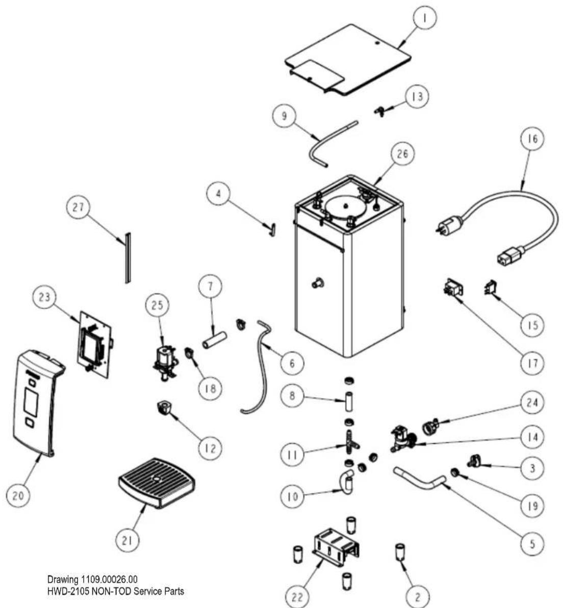
Drawing 1109.00026.00
HWD-2105 NON-TOD Service Parts
| PARTS LIST FOR HWD-2105 NON TOD Service Parts Drawing 1109.00026.00 | |||
| ITEM NO | PART NO DESC | RIPTION QTY | |
| 1 1023.00 | 131.00 TOP COV | VER HWD-2105 1 | |
| 2 | 1023.00136.00 | LEG HWD-2100 4 | |
| 3 1023.00 | 147.00 PLUG, TANK SERVICE DRAIN for 18GA AND UP BODY 1 | ||
| 4 1024.00 | 040.00 CARD PL | UG, HWD-2100 1 | |
| 5 1025.00 | 039.00 TUBE, 5/8" OD X 3/8 ID X 10" LG, DRAIN 1 | ||
| 6 1025.00 | 040.00 TUBE, 1/4" OD X .125" ID X 16" LG, VENT 1 | ||
| 7 1025.00 | 041.00 TUBE, 3/4" OD X 1/2" ID X 2.75" LG, DISPENSE 1 | ||
| 8 1025.00 | 042.00 TUBE, 5/8" OD X 3/8" ID X 2" LG, BOTTOM TANK 1 | ||
| 9 1025.00 | 044.00 TUBE, SILICONE, 5/16" OD X 3/16" ID X 10.5" LG, TANK VENT 1 | ||
| 10 | 1025.00046.00 | TUBE, 5/8" OD X 3/8" ID X 5.0" LG, DOUBLE VALVE | 1 |
| 11 | 1029.00002.00 | FITTING, HOSE BARB TEE, SIZE 3/8", NYLON | 1 |
| 12 | 1029.00017.00 | FAUCET, SILICONE, HWD-2100 | 1 |
| 13 | 1029.00023.00 | FITTING, SINGLE BARBED ELBOW, 1/4", KYNAR | 1 |
| 14 | 1057.00043.00 | SOLENOID VALVE, SINGLE, 180 DEG, 24VDC | 1 |
| 15 | 1058.00020.00 | SWITCH, POWER ROCKER RED, ILLUMINATED 250V 1 | |
| 16 1063.0 | 0001.00 CORD, | POWER, IEC-320-19, 20A/125VAC | 1 | |
| 16 | 1063.00002.00 | CORD, POWER, IEC-320-19, 15A/125VAC | 1 | |
| 17 1065.0 | 0001.00 CONNE | CTOR, IEC POWER EN60320 C20, 0722 SERIES 1 | ||
| 18 1086.0 | 0002.00 CLAMP | HOSE, SIZE "G" NYLON 2 | ||
| 19 1086.0 | 0003.00 UNICLA | MP, 15.9 HOSE OD CLAMP 6 | ||
| 20 1102.0 | 0153.00 FRONT | PANEL TOP, ASSEMBLY HWD-2100 1 | ||
| 21 | 1102.00156.00 | DRIP TRAY ASSEMBLY, HWD-2100 1 | ||
| 22 1102.0 | 0159.00 POWER | SUPPLY ASSEMBLY, HWD-2100 1 | ||
| 23 1102.0 | 0160.00 BOARD | AND DISPLAY ASSEMBLY, HWD-2100 1 | ||
| 24 | 1102.00164.00 | ADAPTER ASSEMBLY, 3/4" BSP X 1/4 SAE FLARE 1 | ||
| 25 | 1102.00167.00 | DISPENSE VALVE ASSEMBLY, HWD-2100 1 | ||
| 26 | 1104.00018.00 | TANK ASSEMBLY, 2100W/120V, HWD-2105 | 1 | |
| 26 | 1104.00031.00 | TANK ASSEMBLY, 1440W/120V, HWD-2105 | 1 | |
| 26 | 1104.00032.00 | TANK ASSEMBLY, 3200W/200-230V, HWD-2105 | 1 | |
| 27 | 1402.00020.00 | HARNESS, UNIVERSAL, HWD-2105 | ||
1
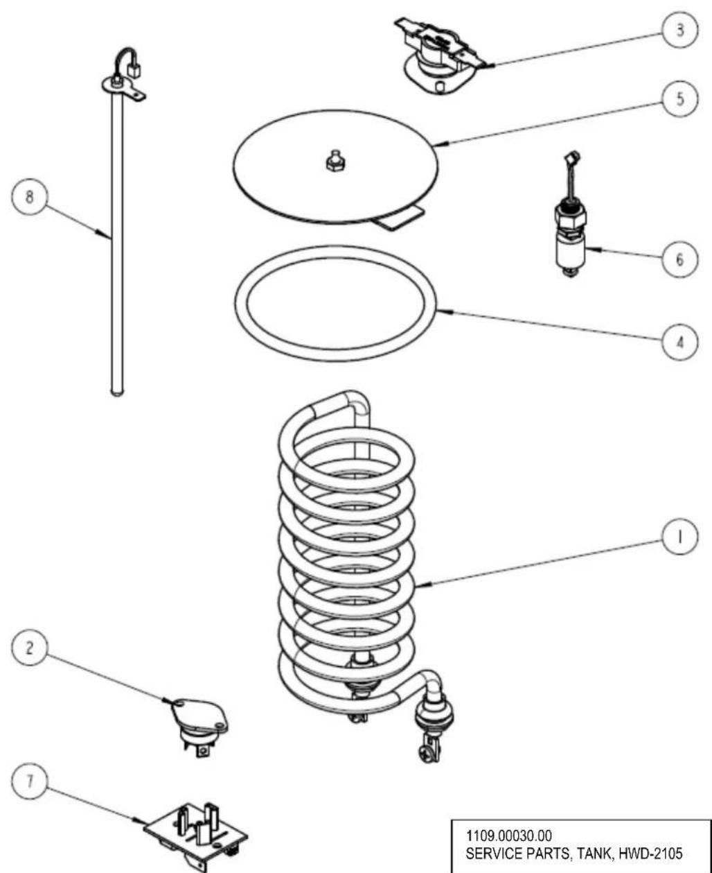
| PARTS LIST FOR HWD-2105 With TOD Hot Water Tank Drawing 1104.00018.00 | |||
| ITEM# | PART# DESCRIPTION QTY | ||
| 1 | 1107.00008.00 | HEATER ASSEMBLY, IMMERSION 2100W/120VAC | 1 |
| 1 | 1107.00014.00 | HEATER ASSEMBLY, IMMERSION 1440W/120VAC | 1 |
| 1 | 1107.00015.00 | HEATER ASSEMBLY, IMMERSION 3200W/200-230VAC EXPORT | 1 |
| 2 | 1059.00001.00 | TRIAC 40A, 600V 1 | |
| 3 1053.00 | 0004.00 THERMOSTAT, SINGLE SHOT, 25A 1 | ||
| 4 1024.00 | 0007.00 O-RING, DASH #344, TANK COVER 1 | ||
| 5 1102.00 | 0007.00 TANK COVER ASSEMBLY 1 | ||
| 6 1054.00 | 0006.00 FILL SENSOR, HWD TOD 1 | ||
| 7 1051.00 | 0016.00 BOARD, TRIAC DRIVE WITH RC FILTER 1 | ||
| 8 | 1102.00161.00 | PROBE ASSEMBLY, TEMP. AND LLC, HWD-2105 1 | |
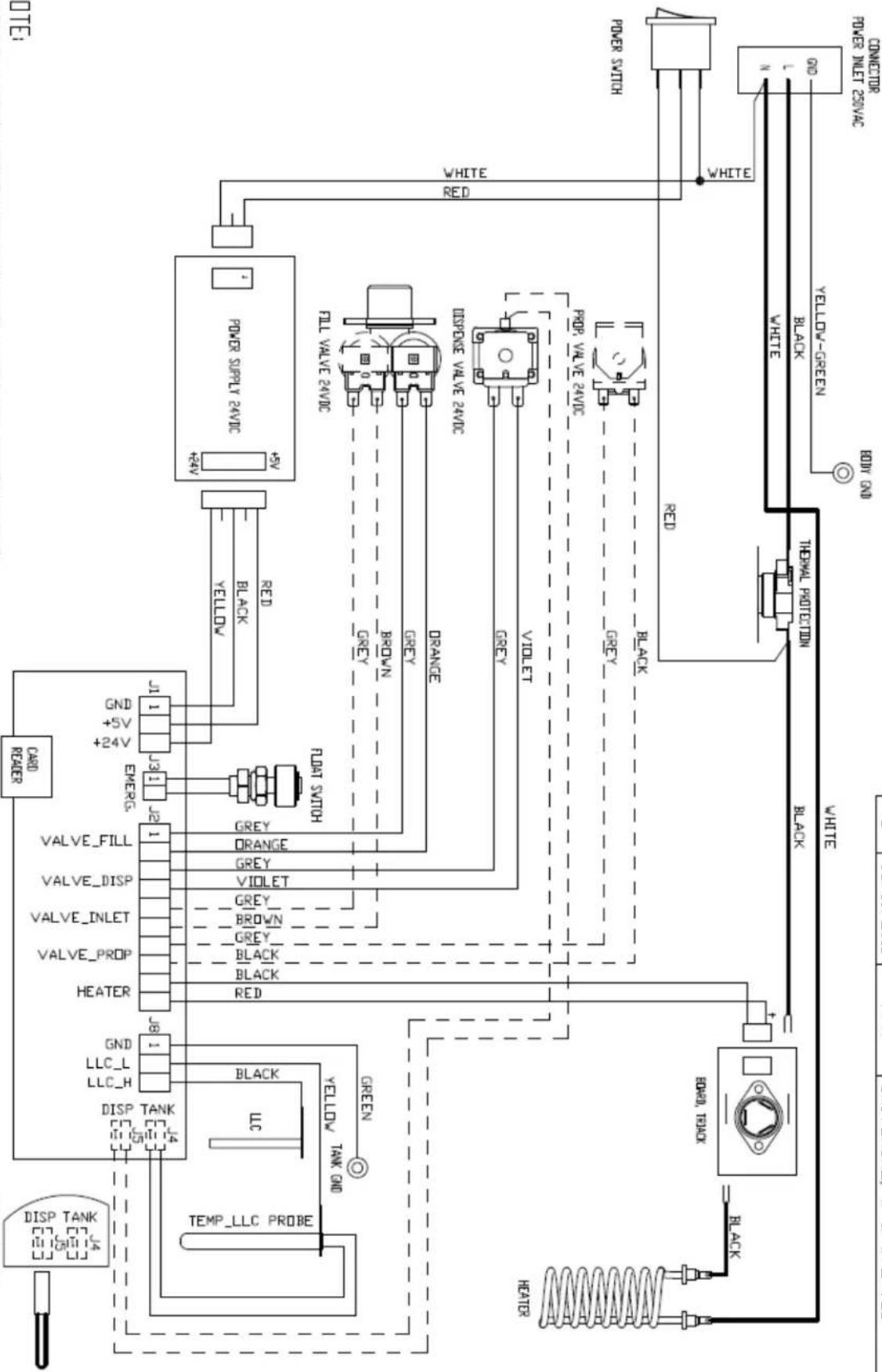
SINGLE VALUE AND NO PROPORTIONAL VALUE, DASHED WIRES IN THE ELECTRICAL HARNESS AND SENSOR ASSY 1102.00151.00 ARE NOT USED BOOK RESISTOR ASSY PN:1059.00002.00 IN PLACE FOR SENSOR ASSY ON THE BOARD SEE DETAIL.A.
NOTE: DASHED LINES INDICATE NON TOP VERSION WHICH USES
| TOTALRANICES | REVISIONS | |||
| NO | DATE | BY | FETCODE | |
| DECIMAL | 4 | 02-08-2011 | AG | VVG NAME:WIRING, HWB-2105 W & V/D 100, LL, N+GND, I HEATHER |
| FRACTIONALN/A | 4 | 06-07-2011 | AG | AV |
| ANCULARN/A | C | X | DRAWN BY AGSCALE N/AMATISTERN/A | |
| X | X | A | SIZE A | |
| A | CHKD | AS | ||
| DATE | 02-08-2011 | CG | APP'D | |
DETAIL, A.
| REV | DATE | ECO NO | DESCRPTION | BY: |
| A | ||||
| A | 02/08/2011 | N/A | ORIGINAL | A |
| B | 06/10/2011 | N/A | UNIVERSAL, W & W/O TDD | A |
- HWD-2105 Hot Water Dispenser
- FETCO® HWD-2105 Hot Water Dispenser
- Contact Information
- Description & Features
- Specifications
- Dimensions & Utility Connections
- Installation
- Setup
- Water Connection
- Electrical Connection
- Final Setup-Fill and Initial Heating
- Operating Instructions
- Operator Training
- Operating Principles
- Cleaning & Maintenance
- Daily:
- Quarterly:
- Notice:
- WARNING:
- Tank Drain
- Control and Operational Screens
- Programming and diagnostic screens
- DETAIL, A.
Brand : Fetco
Model : HWD-2105
Category : Water dispenser