
LIVA One H610 - Desktop computer ECS - Free user manual and instructions
Find the device manual for free LIVA One H610 ECS in PDF.


| Product Type | Desktop Computer (SFF Mini PC, 1.1L chassis) |
| Dimensions | 205 mm (H) x 176 mm (D) x 33 mm (W) |
| Weight | Approx. 1.0 kg (estimated) |
| Power Supply | 120W power adapter (19V / 6.32A) |
| Processor Support | Intel LGA1700 socket: 12th/13th Gen Core, Pentium, Celeron (up to 65W TDP) |
| Chipset | Intel H610 |
| Memory | 2x DDR4 SO-DIMM, dual-channel, up to 64 GB, 3200 MHz |
| Storage Support | 1x 2.5" SATA III HDD/SSD (not included); M.2 SSD not specified |
| Graphics Output | 2 x DP 1.4, 1 x HDMI 2.0, 1 x D-Sub/RS232 (optional); supports up to 3 displays |
| Networking | Realtek 2.5 Gigabit Ethernet; M.2 2230 Key E for Wi-Fi 802.11ax (CNVi/PCIe) |
| USB Ports (Front) | 2 x USB 3.2 Gen 1 Type-A, 2 x USB 3.2 Gen 2 Type-C |
| USB Ports (Rear) | 2 x USB 2.0, 2 x USB 3.2 Gen 1 |
| Audio | 1 x Combo jack (headphone/mic), 1 x Mic-in |
| Operating System | Windows 11 (supported) |
| Security | Kensington lock; TPM 2.0 support; BIOS password |
| Mounting | VESA mount bracket included |
| Cooling | Active fan cooling (heatsink included) |
| Package Contents | Quick Installation Guide, VESA mount & stand, 120W power adapter, cooler; memory/CPU/SSD/HDD not included |
| Additional Features | Low power consumption, space-saving 1.1L design, Multi-Monitor support |
Frequently Asked Questions - LIVA One H610 ECS
User questions about LIVA One H610 ECS
0 question about this device. Answer the ones you know or ask your own.
Ask a new question about this device
Download the instructions for your Desktop computer in PDF format for free! Find your manual LIVA One H610 - ECS and take your electronic device back in hand. On this page are published all the documents necessary for the use of your device. LIVA One H610 by ECS.
USER MANUAL LIVA One H610 ECS
This publication, including all photographs, illustrations and software, is protected under international copyright laws, with all rights reserved. Neither this manual, nor any of the material contained herein, may be reproduced without written consent of the author.
Version 1.0
Disclaimer
The information in this document is subject to change without notice. The manufacturer makes no representations or warranties with respect to the contents hereof and specifically disclaims any implied warranties of merchantability or fitness for any particular purpose. The manufacturer reserves the right to revise this publication and to make changes from time to time in the content hereof without obligation of the manufacturer to notify any person of such revision or changes.
Trademark Recognition
Windows ® 11 are registered trademarks of Microsoft Corp.
Other product names used in this manual are the properties of their respective owners and are acknowledged.
Federal Communications Commission (FCC)
This equipment has been tested and found to comply with the limits for a Class B digital device, pursuant to Part 15 of the FCC Rules. These limits are designed to provide reasonable protection against harmful interference in a residential installation. This equipment generates, uses, and can radiate radio frequency energy and, if not installed and used in accordance with the instructions, may cause harmful interference to radio communications. However, there is no guarantee that interference will not occur in a particular installation. If this equipment does cause harmful interference to radio or television reception, which can be determined by turning the equipment off and on, the user is encouraged to try to correct the interference by one or more of the following measures:
• Reorient or relocate the receiving antenna
- Increase the separation between the equipment and the receiver
- Connect the equipment onto an outlet on a circuit different from that to which the receiver is connected
- Consult the dealer or an experienced radio/TV technician for help
Any changes or modifications not expressly approved by the grantee of this device could void the user's authority to operate the equipment. This equipment complies with FCC radiation exposure limits set forth for an uncontrolled environment. This equipment should be installed and operated with minimum distance 20cm between the radiator & your body.
The terms HDMI, HDMI High-Definition Multimedia Interface, and the HDMI Logo are trademarks or registered trademarks of HDMI Licensing Administrator, Inc.
Declaration of Conformity
This device complies with part 15 of the FCC rules. Operation is subject to the following conditions:
• This device may not cause harmful interference, and
- This device must accept any interference received, including interference that may cause undesired operation.
Canadian Department of Communications
This class B digital apparatus meets all requirements of the Canadian Interference-causing Equipment Regulations.
Your system is designed and tested to meet the latest standards of safety for information technology equipment. However, to ensure your safety, it is important that you read the following safety instructions.
Setting up your system
- Read and follow all instructions in the documentation before you operate your system.
- Do not use this product near water or a heated source such as a radiator.
- Set up the system on a stable surface.
- Openings on the chassis are for ventilation. Do not block or cover these openings. Make sure you leave plenty of space around the system for ventilation. Never insert objects of any kind into the ventilation openings.
- Use this product in environments with ambient temperatures between 0°C and 40°C.
- If you use an extension cord, make sure that the total ampere rating of the devices plugged into the extension cord does not exceed its ampere rating.
- Only technicians are allowed to open the chassis, please contact with your vendor / supplier for any technical support.
Attention during use
- Do not step on the power cord or let anything rest on top of it.
- Do not spill water or any other liquid on your system.
- When the system is turned OFF, a small amount of electrical current still flows. Always unplug all power, modem, and network cables from the power outlets before cleaning the system.
-
If you encounter the following technical problems with the product, unplug the power cord and contact a qualified service technician or your retailer.
-
The power cord or plug is damaged.
- Liquid has been spilled into the system.
- The system does not function properly even if you follow the operating instructions.
- The system was dropped or the cabinet is damaged.
• The system performance changes

The warranty does not apply to products that have been disassembled by users
Safety cautions and warnings
Product disposal notice

IMPORTANT:
This symbol if the crossed out wheeled bin indicates that the product (electrical and electronic equipment) should not be placed in municipal waste. Check local regulations for disposal of electronic products.
Nordic Lithium Cautions (for lithium-ion batteries)

CAUTION:
Danger of explosoin if battery is incorrectly replace only with the same or equivalent type recommended by the manufacturer. Dispose of used batteries according to the manufacturer's instructions.
Product disposal notice

- Do not place this product underneath heavy loads or in an unstable position.
- Do not use or expose this product around magnetic fields as magnetic interference may affect the performance of the product.
- Do not expose this product to high levels of direct sunlight, highhumidity or wet conditions.
- Do not block the air vents to this product or impede the airflow in any way.
Warning

Do not ingest battery, Chemical Bum Hazard
This Product contains a coin/button cell battery. If the coin /button cell battery is swallowed, it can cause severe internal burns in just 2 hours and lead to death.
Keep new and used batteries away from children.
If battery compartment does not close securely, stop using the product and keep it away from children.
If you think batteries might have be swallowed or placed inside any part of the body, seek immediate medical attention.
Manufactured by
Elitegroup Computer Systems Co., Ltd
No.239, Sec.2, Tiding Blvd., Taipei, Taiwan 11493
+886-2-2162-1177
Preface i
Chapter 1 1
Introducing the PC 1
Introduction....1
Specification 2
Front and Rear I/O 3
Packing Contents ....5
Chapter 2 7
Installing the PC 7
System Quick Installation 7
Chapter 3 9
Using BIOS 9
About the Setup Utility....9
The Standard Configuration....9
Entering the Setup Utility....9
Using BIOS....10
BIOS Navigation Keys....11
Main Menu 12
Advanced Menu....13
Chipset Menu....25
Tweak Menu 32
Security Menu 38
Boot Menu 39
Exit Menu....41
Updating the BIOS 42
Chapter 4 43
Trouble Shooting 43
Trouble shooting and problem solution....43
vi
Memo
Chapter 1 Introducing the PC
Introduction
Thank you for choosing this 1.1L case of great performance and with stylish and flexible design.
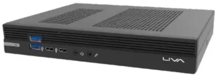
Supports LGA1700 Socket for Intel ® 12th and 13th Generation Core ™ , Pentium ® and Celeron ® and a dimension of 205mm (H)* 176mm (D)* 33mm (W), 1.1L SFF provides the features of low power consumption (working with a 120Watt power adapter), and space saving. This Model uses Intel ® LGA1700, supporting up to 64 GB of system memory with DDR4 memory SO-DIMM, 2.5" SATA III HDD, 3 independent displays.

natural_image
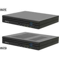
Exterior view of a black LIVA desktop computer chassis (no visible text or symbols on body)35W SKU
natural_image
Front view of a black LIVA desktop computer chassis with ventilation grilles and ports (no visible text or symbols beyond branding)65W SKU

Note:
ID design may vary.
Specifications
| Chipset | Intel® H610 Chipset |
| CPU • | LGA1700 socket, support Intel® 12th and 13th Generation CoreTM, Pentium® and Celeron® processorsSupports CPU up to 65W |
| Memory • | Dual-channel SO-DIMM DDR4 3200MHz max, up to 64 GB |
| LAN • | Realtek 2.5 Gigabit Ethernet |
| Wi-Fi • | M.2 2230 Key E, CNVi/PCIe wireless cardSupports 802.11ax, 2x2 |
| Video Output • | 2 x DP 1.4 ports1 x HDMI 2.0 port1 x D-Sub/RS232 port (optional)(max. 3 Displays) |
| Front Panel • | 1 x Power button• 2 x USB 3.2 Gen 1x1• 2 x USB 3.2 Gen 2x1 Type-C• 1 x Combo jack• 1 x MIC-in |
| Rear Panel • | 1 x Kensington lock• 1 x DC-in• 2 x DP 1.4 ports• 1 x HDMI 2.0 port• 1 x VGA/RS232 port (optional)• 1 x 2.5 Gigabit Ethernet• 2 x USB 2.0 ports• 2 x USB 3.2 Gen 1x1 ports |
| Adapter • | 35W & 65W: 19V/6.32A, 120W power adapter |
| OS Support • | Windows 11 |
| Kensington lock • | Supported |
| Dimensions (mm) • | 205mm (H)* 176mm (D)* 33mm (W) |
Front and Rear I/O

- Power Button with LED Press the power button to turn the system on and off.
- HDD LED This is the HDD LED light.
- USB 3.2 Gen 1x1 Type A The USB 3.2 Gen 1x1 connectors are used for devices with USB, such as mouse, keyboard, printer, scanner.
- USB 3.2 Gen 2x1 Type-C The USB 3.2 Gen 2x1 Type-C connector is used for devices with USB Type-C.
- Combo Jack Connecting headset.
- Mic In Jack Connecting microphone.
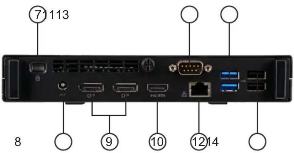
- Kensington Lock This is the security lock.
- DC Jack It is used for power adapter.
- DP Ports Connecting display devices to the DP ports.
- HDMI Port Connecting a display device to the HDMI port.
- D-SUB Connector or Connecting VGA Monitor.
COM Port (optional) Connecting a device with COM port.
- LAN Connecting the Network.
- USB 3.2 Gen 1x1 Connectors Connecting USB 3.0 compatible devices.
- USB 2.0 Connectors Connecting USB 2.0 compatible devices.
Packing Contents

Quick Installation Guide

natural_image
3D rendered image of a dark gray plastic tray or cover with cutouts and a small central slot (no text or symbols)Stand VESA Mount

natural_image
Black metal door panel with a handle and mounting holes, no visible text or symbols
natural_image
Exterior view of a black rectangular electronic device with attached cable and power cord (no visible text or symbols)Power 120W
CPU TDP 35W & 65W
natural_image
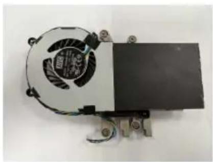
Top-down view of a small electronic device with a fan and cooling unit (no visible text or symbols)Cooler

NOTE: Please contact us immediately if any of the items is damaged or missing. (Memory, SSD, CPU and HDD are required to be purchased additionally.)
Memo
Chapter 2 Installing the PC
System Quick Installation
- Connecting HDMI device.
natural_image
Large CRT television displaying a landscape scene with a red figure on a cliff and blue sky (no visible text or symbols)
natural_image
Back panel of a network device showing ports, connectors, and a red circular connector (no visible text or labels)- Connecting VGA Monitor. (D-SUB Connector)

natural_image
Front view of a black flat-screen computer monitor (no visible text or symbols)
natural_image
Back panel of a network device showing ports, connectors, and an external port with a red circle highlighting the connector (no visible text or symbols)- The USB connectors are used for attaching USB devices, such as mouse, keyboard, printer, scanner and other USB-compatible device.

natural_image
Blue computer keyboard with mouse, USB drive, and card slot (no text or symbols visible)
natural_image
Back panel of a network device showing ports, connectors, and a highlighted port (no visible text or labels)- Attaching Ethernet cable here. (LAN Connector)

natural_image
Coiled blue network cable with connectors (no text or symbols visible)
natural_image
Back panel of a network device showing ports, connectors, and an Ethernet port (no visible text or labels)- Connecting the Microphone. (Microphone Jack)


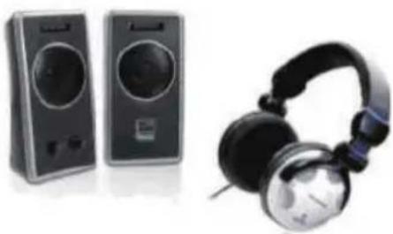
- Connecting Speakers or Headphones. (Headphone Jack)
natural_image
Product photo of audio equipment including two speakers and a pair of headphones (no visible text or labels)
- Connecting Power. (DC jack)

natural_image
Electricity charger with black cable and earplifier (no visible text or symbols)
natural_image
Back panel of a network device showing ports, connectors, and a highlighted connection point (no readable text or symbols)About the Setup Utility
The computer uses the latest “American Megatrends Inc.” BIOS with support for Windows Plug and Play. The CMOS chip on the motherboard contains the ROM setup instructions for configuring the motherboard BIOS.
The BIOS (Basic Input and Output System) Setup Utility displays the system's configuration status and provides you with options to set system parameters. The parameters are stored in battery-backed-up CMOS RAM that saves this information when the power is turned off. When the system is turned back on, the system is configured with the values you stored in CMOS.
The BIOS Setup Utility enables you to configure:
- Hard drives, diskette drives and peripherals
• Video display type and display options - Password protection from unauthorized use
• Power Management features
The settings made in the Setup Utility affect how the computer performs. Before using the Setup Utility, ensure that you understand the Setup Utility options.
This chapter provides explanations for Setup Utility options.
The Standard Configuration
A standard configuration has already been set in the Setup Utility. However, we recommend that you read this chapter in case you need to make any changes in the future.
This Setup Utility should be used:
- when changing the system configuration
- when a configuration error is detected and you are prompted to make changes to the Setup Utility
- when making changes to the Power Management configuration
- when changing the password or making other changes to the Security Setup
Entering the Setup Utility
When you power on the system, BIOS enters the Power-On Self Test (POST) routines. POST is a series of built-in diagnostics performed by the BIOS. After the POST routines are completed, the following message appears:
Press DEL to enter SETUP
Press the delete key to access BIOS Setup Utility.

Using BIOS
When you start the Setup Utility, the main menu appears. The main menu of the Setup Utility displays a list of the options that are available. A highlight indicates which option is currently selected. Use the cursor arrow keys to move the highlight to other options. When an option is highlighted, execute the option by pressing
Some options lead to pop-up dialog boxes that prompt you to verify that you wish to execute that option. Other options lead to dialog boxes that prompt you for information.
Some options (marked with an icon) lead to submenus that enable you to change the values for the option. Use the cursor arrow keys to scroll through the items in the submenu.
In this manual, default values are enclosed in parenthesis. Submenu items are denoted by an icon >>.

The default BIOS setting for this motherboard apply for most conditions with optimum performance. We do not suggest users change the default values in the BIOS setup and take no responsibility to any damage caused by changing the BIOS settings.
BIOS Navigation Keys
The BIOS navigation keys are listed below:
| KEY FUNCTION | |
| ESC Exits the current menu | |
| ↑↓→← | Scrolls through the items on a menu |
| +/- Change Opt. | |
| Enter Select | |
| F1 General Help | |
| F2 Previous Value | |
| F3 Optimized Defaults | |
| F4 Save & Exit | |

- For the purpose of better product maintenance, the manufacture reserves the right to change the BIOS items presented in this manual. The BIOS setup screens shown in this chapter are for reference only and may differ from the actual BIOS. Please visit the manufacture's website for updated manual.
- In this Gui BIOS, you can operate by mouse or keyboard. Click : select item; Double click: enter; Right click: exit.
Default
Select the default icon and press
Advanced
Select the advanced icon and press
Exit
Select the exit icon and press
Main Menu
This menu shows the information of BIOS and enables you to set the system language, date and time.

System Language (English)
This item is used to set system language.
System Date & Time
The Date and Time items show the current date and time on the computer. If you are running a Windows OS, these items are automatically updated whenever you make changes to the Windows Date and Time Properties utility.
Advanced Menu
The Advanced menu items allow you to change the settings for the CPU and other system.
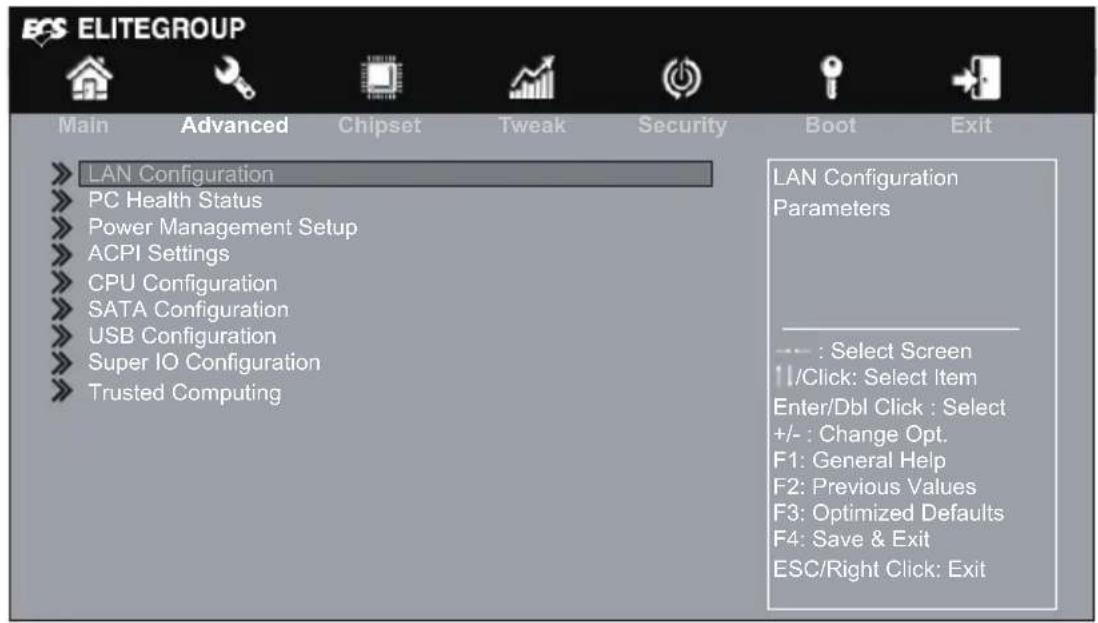
» LAN Configuration
The item in the menu shows the LAN-related information that the BIOS automatically detects.

Onboard LAN Controller (Enabled)
Use this item to enable or disable Onboard LAN controller.
Press
» PC Health Status
On motherboards support hardware monitoring, this item lets you monitor the parameters for critical voltages, temperatures and fan speeds.
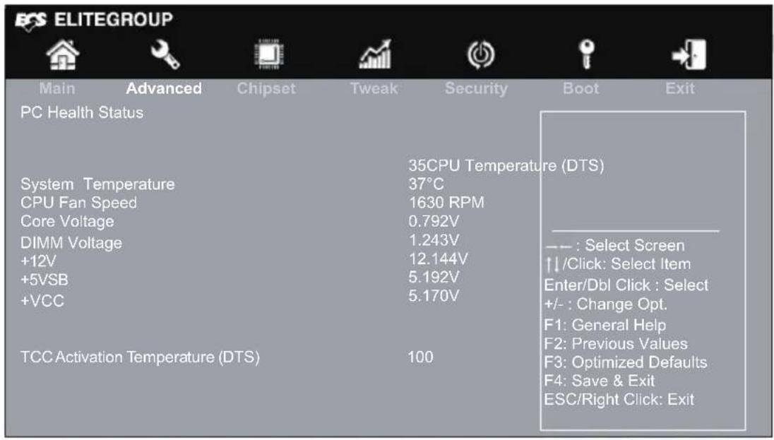
System Component Characteristics
These items display the monitoring of the overall inboard hardware health events, such as CPU & DIMM voltage, CPU & System fan speed...etc.
- CPU Temperature
• System Temperature - CPU Fan Speed
- Core Voltage
- DIMM Voltage
+12V
+5VSB
• +VCC
TCC Activation Temperature (DTS) (100)
This item show the TCC Activation Temperature.
Press
» Power Management Setup
This page sets up some parameters for system power management operation.

Resume By RING (Disabled)
An input signal on the serial Ring Indicator (RI) line (in other words, an incoming call on the modem) awakens the system from a soft off state.
Resume By PME (Disabled)
The system can be turned off with a software command. If you enable this item, the system can automatically resume if there is an incoming call on the PCI/PCI-E Modem or PCI/PCI-E LAN card. You must use an ATX power supply in order to use this feature. Use this item to do wake-up action if inserting the PCI/PCI-E card.
Resume By USB (Disabled)
This item allows you to enable or disable the USB device wakeup function from S3 mode.
Resume By RTC Alarm (Disabled)
The system can be turned off with a software command. If you enable this item, the system can automatically resume at a fixed time based on the system's RTC (realtime clock). Use the items below this one to set the date and time of the wake-up alarm. You must use an ATX power supply in order to use this feature.
EUP Function (Enabled)
This item allows user to enable or disable EUP support.
System Power select (65W)
This item allows user to adjust System Power.
Press
» ACPI Settings
The item in the menu shows the highest ACPI sleep state when the system enters suspend.

ACPI Sleep State [S3(Suspend to RAM)]
This item allows user to enter the ACPI S3 (Suspend to RAM) Sleep State (default).
Press
» CPU Configuration
The item in the menu shows the CPU.

12th Gen Inter(R) Core(TM) i3-12300T
This is display-only field and displays the information of the CPU installed in your computer.
Processor Speed (2300 MHz)
This item shows the processor speed.
ID (0x90675)
This item shows the processor ID.
Microcode Revision (1E)
This item shows the Microcode Revision.
VMX (Supported)
This item shows the computer supports the VMX or not.
SMX/TXT (Not Supported)
This item shows the computer supports the SMX/TXT or not.
Hyper-Threading (Enabled)
This item is only available when the chipset supports Hyper-Threading and you are using a Hyper-Threading CPU.
Use this item to enable or disable the maximum CPUID value limit, you can enable this item to prevent the system from "ebooting" when trying to install Windows NT 4.0.
Intel (VMX) Virtualization Technology (Enabled)
When disabled, a VMM cannot utilize the additional hardware capabilities provided by Vandor Pool Technology.
Package C State Limit (Auto)
Use this item to set the Package C State limit.
Enhanced Halt (C1E) (Enabled)
Use this item to enable or disable the Enhanced C1 state.
Intel(R) Speed Shift Technology (Enabled)
Use this item to enable the CPU energy-saving function when the system is not running.
Press
» SATA Configuration
Use this item to show the mode of serial SATA configuration options.

SATA Mode Selection (AHCI)
Use this item to select SATA mode.
SATA Port 1 [TPSJOBA Q300. (120.0GB)]
This item shows the SATA Port 1 Device.
SATA Port 2 (Not Present)
This item shows the SATA Port 2 Device.
Press
» USB Configuration
Use this item to show the information of USB configuration.

All USB Devices (Enabled)
Use this item to enable or disable all USB devices.
Press
» Super IO Configuration
Use this item to show the information of Super IO configuration.

Super IO Chip (IT8613)
This item shows the information of the super IO chip.
» Serial Port 1 Configuration
Scroll to this item and press

Serial Port (Enabled)
This item allows you to enable or disable serial port.
Device Settings (IO=3F8h; IRQ=4)
This item shows the information of the device settings.
Change Settings (Auto)
Use this item to change device settings.
Press
» Trusted Computing
Use this item to show the information of trusted computing configuration.

TPM Support (Enabled)
Use this item to enable or disable the TPM support. O.S. will not show TPM. Reset of platform is required.
Active PCR banks (SHA256)
Use this item to show the Active PCR banks.
Available PCR banks (SHA256, SHA384, SM3)
Use this item to show the Available PCR banks.
SHA256 PCR Bank (Enabled)
Use this item to enable or disable the SHA256 PCR bank.
SHA384 PCR Bank (Disabled)
Use this item to enable or disable the SHA384 PCR bank.
SM3\_256 PCR Bank (Disabled)
Use this item to enable or disable the SM3_256 PCR bank.
Pending operation (None)
Schedule an Operation for the Security Device. NOTE: Your Computer will reboot during restart in order to change State of Security Device.
Platform Hierarchy (Enabled)
Use this item to enable or disable the platform hierarchy.
Storage Hierarchy (Enabled)
Use this item to enable or disable the storage hierarchy.
Endorsement Hierarchy (Enabled)
Use this item to enable or disable the Endorsement hierarchy.
Physical Presence Spec Version (1.3)
Use this item to show the Physical Presence Spec Version.
TPM 20 Interface Type (CRB)
Use this item to select the communication interface to TPM 20 device.
Press
Chipset Menu
The chipset menu items allow you to change the settings for the North Bridge chipset, South Bridge chipset and other system.

» System Agent Configuration
Scroll to this item and press
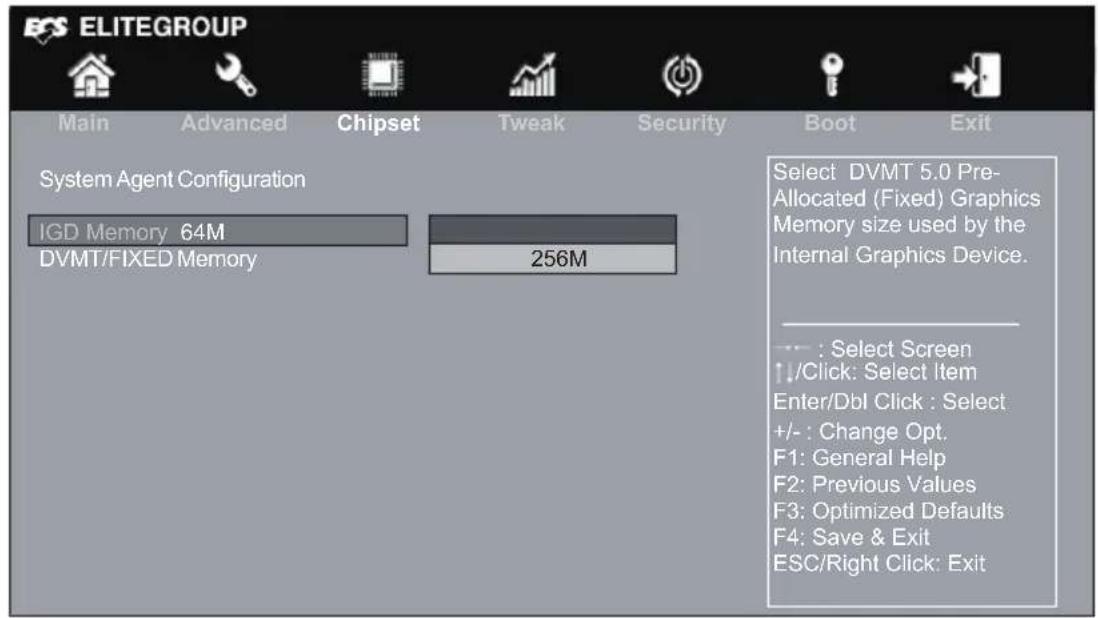
IGD Memory (64M)
This item shows the information of the IGD (Internal Graphics Device) memory.
DVMT/FIXED Memory (256M)
When set to Fixed Mode, the graphics driver will reserve a fixed position of the system memory as graphics memory, according to system and graphics requirement.
Press
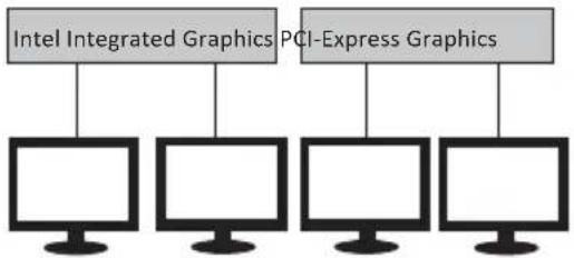
Multi-Monitor technology
Multi-Monitor technology can help you to increase the area available for programs running on a single computer system through using multiple display devices.
It is not only to increase larger screen viewing but aslo to improving personal productivity.
flowchart
graph TD
    A["Intel Integrated Graphics"] --> B["Computer"]
    C["PCI-Express Graphics"] --> D["Computer"]
    B --> E["Computer"]
    D --> F["Computer"]

Please note that Multi-Monitor technology supports up to four monitors: one or two Intel integrated Graphics and one or two PCI-Express graphics devices under Windows 11/10.
Step 1. Insert ECS drives DVD to run Auto setup or browse the DVD to install Intel chipset drivers, VGA and sound drivers. (If you want know the detail information, please refer to chapter 4.)
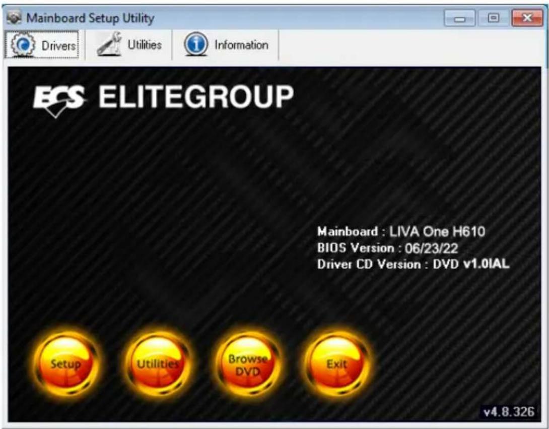
Step 2. Install all the drivers of PCI-Express graphic cards. Click the Browse CD item, then appears the following screen. Select the driver you want to install(e.g NVIDIA GeForce 8400 GS(Microsoft Corporation-WDDM v1.1)) and double click it.

Step 3. Enable IGD Multi-Monitor from BIOS. In the following BIOS screen, please set IGD Multi-Monitor to [Enabled].

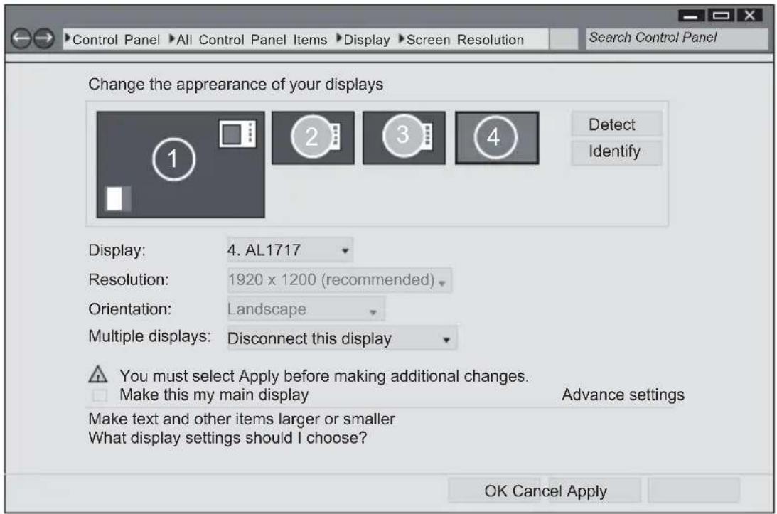
Step 4. Change the appearance of your displays under Windows 11/10. The following pictures are for reference only, please focus on the actual operation interface.
- Enter the Control Panel menu, select the Display in the All Control Panel Items and click the Screen Resolution, then appears the following screen.

- Select display devices, set the multiple displays option and to extend destop for display "Multi-Monitor technology".


» PCH Configuration
Scroll to this item and press

Restore AC Power Loss (Power Off)
This item enables your computer to automatically restart or return to its operating status.
HD Audio (Enabled)
This item enables or disables Azalia HD audio.
Case Open Warning (Disabled)
Use this item to enable or disable the warning if the case is opened up, and the item below indicates the current status of the case.
Chassis Opened (No)
This item indicates whether the case has been opened.
Press
» ME Configuration
Scroll to this item and press

ME Control (Enabled)
Use this item to enable or disable the ME Firmware.
ME FW Version (16.0.15.1735)
This item shows the ME FW version.
Tweak Menu
This page enables you to set the clock speed and system bus for your system. The clock speed and system bus are determined by the kind of processor you have installed in your system.

» CPU OverClocking Configuration
Scroll to this item and press

EIST (Enabled)
This item allows users to enable or disable the EIST (Enhanced Intel SpeedStep Technology).
Turbo Boost (Enabled)
Use this item to enable or disable the turbo boost.
Power Limit 1 Override (Enabled)
Use this item to enable or disable the Power Limit 1 Override. If this option is disabled, BIOS will program the default values for Power Limit 1.
Power Limit 1 Value (Maximum)
Power limit 1 in Milli Watts and stepsize is 125mW .XE SKU: Any value can be programmed. Overclocking SKU: Value must be between Max and Min Power Limits (specified by PACKAGE_POWER_SKU_MSR). Other SKUs: This value must be between Min Power Limit and TDP Limit. If value is 0, BIOS will program TDP value.
Power Limit 1 Time Window (28)
Power limit 1 Time Window value in seconds. The value may vary from 0 to 128. If the value is 0, default values will be programmed (28 sec for Mobile and 1 sec for Desktop). Indicates the time window over which TDP value should be maintained.
Power Limit 2 Override (Enabled)
Use this item to enable or disable the Power Limit 2 Override. If this option is disabled, BIOS will program the default values for Power Limit 2.
Power Limit 2 Value (Maximum)
Power limit 2 value in Milli Watts and stepsize is 125mW. If the value is 0, BIOS will program this value as 1.25*TDP. Processor applies control policies such that the package power does not exceed this limit.
» Power Limit 3 Settings
Scroll to this item and press
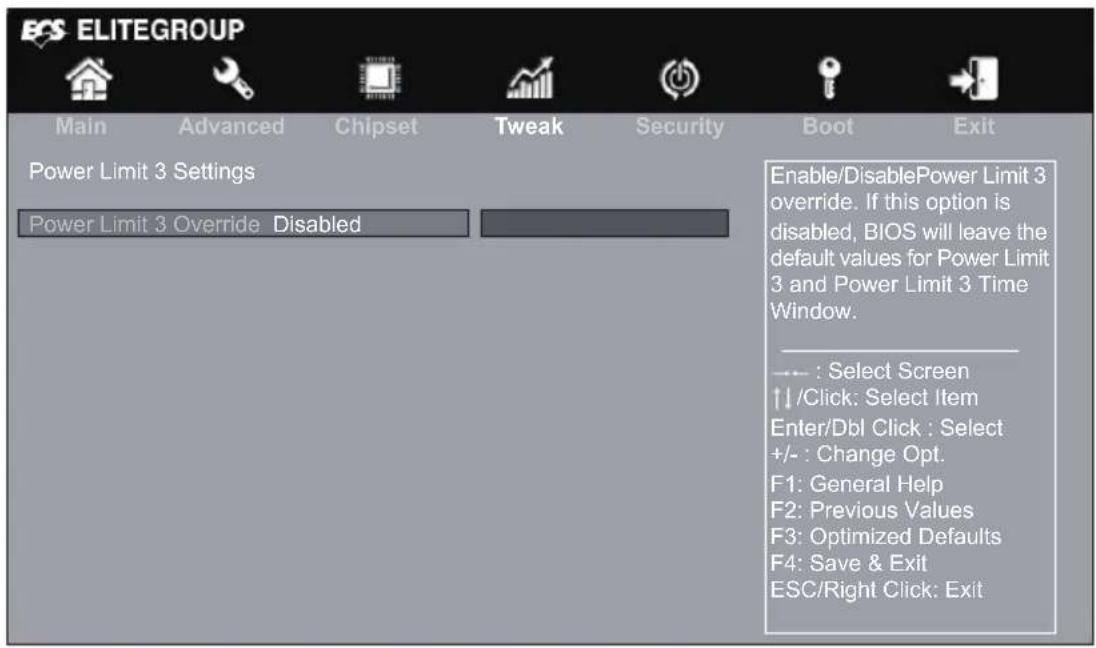
Power Limit 3 Override (Disabled)
Use this item to enable or disable the Limit 3 Override. If this option is disabled, BIOS will leave the default values for Power Limit 3 and power limit 3 time window.
Press
» Power Limit 4 Settings
Scroll to this item and press

Power Limit 4 Override (Enabled)
Use this item to enable or disable the Limit 4 Override. If this option is disabled, BIOS will leave the default values for Power Limit 4 and power limit 4 time window.
Power Limit 4 (95000)
Use this item to set the value of Power Limit 4.
Power Limit 4 Lock (Disabled)
Use this item to enable or disable Power Limit 4 lock.
Press
Boot Performance mode (Max Non-Turbo Perfor...)
Use this item to select the performance state that the BIOS will set before OS handoff.
TDP Lock (Disabled)
This item allows you to enable or disable the Package TDP lock.
CPU Ratio (23)
This item allows you to control CPU ratio.
Turbo Ratio Limit Ration 0/1/2/3 (42/42/38/38)
Use these items to set the Turbo Ratio Limit Ratio value.
Press
» Memory Configuration
Scroll to this item and press

Memory Profile (Default SPD profile)
This item enables you to set the memory profiles. The selection of memory profiles impacts memory sizing behavior.
Memory Frequency (2400)
This item shows the memory frequency.
eDRAM Mode (eDRAM HW Mode)
Use this item to set the eDRAM mode.
Retrain on Fast Fail (Enabled)
Use this item to enable or disable restrain on fast fail.
Exit On Failure (MRC) (Enabled)
Use this item to enable or disable the exit on failure (MRC).
Ch Hash Support (Enabled)
Use this item to enable or disable the Ch Hash support.
Memory Scrambler (Enabled)
Use this item to enable or disable the memory scrambler.
Memory Remap (Enabled)
Use this item to enable or disable the memory remap above 4G.
Fast Boot (Enabled)
This item allows you to enable or disable the fast boot.
Memory Thermal Management (Enabled)
This item allows you to enable or disable the memory thermal management.
DDR PowerDown and idle counter (BIOS)
This item allows you to BIOS or PCODE the DDR Power Down and idle counter. BIOS: BIOS is in control of DDR CKE mode and idle timer value. PCODE: pcode will manage the modes.
SelfRefresh Enable (Enabled)
This item allows you to enable or disable the SelfRefresh.
Press
12th Gen Inter(R) Core(TM) i3-12300T
This is display-only field and displays the information of the CPU installed in your computer.
Processor Speed (2300 MHz)
This item shows the processor speed.
Memory Frequency (2400MHz)
This item shows the information of the memory frequency.
This item shows the information of the total memory.
Security Menu
This page enables you to set setup administrator password and user password.

Administrator Password Status (Not Install)
This item shows administrator password installed or not.
User Password Status (Not Install)
This item shows user password installed or not.
System Mode state (Setup)
This item shows system mode setup or not.
Secure Boot state (Not Active)
This item allows you to enable or disable the secure boot state.
Secure Boot (Enabled)
This item is used to control the secure boot flow, it is possible only if system runs in User Mode.
Secure Boot Mode (Standard)
This item is used to select the secure boot mode.
Boot Menu
This page enables you to set the keyboard NumLock state.
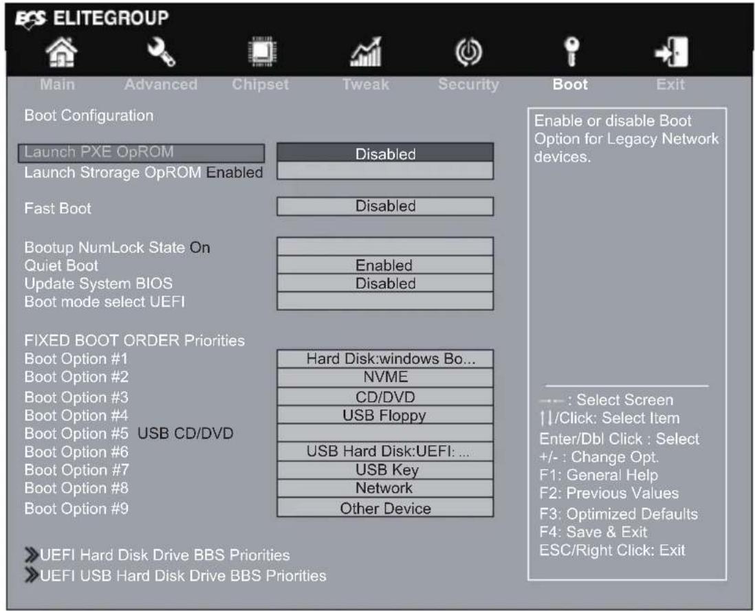
Launch PXE OpROM (Disabled)
The item enables or disables launch PXE Option ROM.
Launch Storage OpROM (Enabled)
Use this item to enable or disable the Storage OpROM.
This item enables or disables boot with initialization of a minimal set of device required to launch active boot option. Has no effect for BBS boot options.
Bootup NumLock State (On)
This item enables you to select NumLock state.
Quiet Boot (Enabled)
This item enables or disables quiet boot.
Update System BIOS (Disabled)
This item enables or disables Update System BIOS.
Boot mode select (UEFI)
Use this item to select boot mode.
These items show the boot priorities.
» UEFI Hard Disk Drive BBS Priorities
This item enables you to specify the sequence of loading the operating system from the installing UEFI Disk drive. Press
» UEFI USB Hard Disk Drive BBS Priorities
This item enables you to specify the sequence of loading the operating system from the installing USB Key drive. Press
Exit Menu
This page enables you to exit system setup after saving or without saving the changes.

Back to EZ Mode
This item enables you to back to EZ mode.
Save Changes and Exit
This item enables you to exit the system setup after saving the changes.
Discard Changes and Exit
This item enables you to exit system setup without saving any changes.
Save Changes and Reset
This item enables you to reset system setup after saving the changes.
Discard Changes and Reset
This item enables you to reset system setup without saving any changes.
Save Options
This item enables you to save the options that you have made.
Save Changes
This item enables you to save the changes that you have made.
Discard Changes
This item enables you to discard any changes that you have made.
Restore Defaults
This item enables you to restore defaults to all the setup options.
Save as User Defaults
This item enables you to save the changes that you have made as user defaults.
This item enables you to restore the user defaults.
Boot Override
Use this item to select the boot device.
Updating the BIOS
You can download and install updated BIOS for this motherboard from the manufacturer's Website. New BIOS provides support for new peripherals, improvements in performance, or fixes for known bugs. Install new BIOS as follows:
1 If your motherboard has a BIOS protection jumper, change the setting to allow BIOS flashing.
2 If your motherboard has an item called Firmware Write Protect in Advanced BIOS features, disable it. (Firmware Write Protect prevents BIOS from being overwritten.)
3 Prepare a bootable device or create a bootable system disk. (Refer to Windows online help for information on creating a bootable system disk.)
4 Download the Flash Utility and new BIOS file from the manufacturer's Web site. Copy these files to the bootable device.
5 Turn off your computer and insert the bootable device in your computer. (You might need to run the Setup Utility and change the boot priority items on the Advanced BIOS Features Setup page, to force your computer to boot from the bootable device first.)
6 At the fs0:> prompt, type the Flash Utility program name and the file name of the new BIOS and then press
7 When the installation is complete, remove the bootable device from the computer and restart your computer. If your motherboard has a Flash BIOS jumper, reset the jumper to protect the newly installed BIOS from being overwritten. The computer will restart automatically.
This concludes Chapter 3. Refer to the next chapter for information on the software supplied with the motherboard.
Chapter 4 Trouble Shooting
Troubleshooting and problem solution
After assembling the PC for the first time you may experience some start up problems. Before calling for technical support or returning for warranty, this chapter may help to address some of the common questions using some basic troubleshooting tips.
a) Boot up failed.
- Use the specified adapter provided by ECS
- Check whether the adapter has been plugged in.
- Check the connection between adapter and the system.
- Check that the power button can be pushed normally. If it is successfully power on, the white light from LED will show up.
- If the boot up problem still exists after these checking steps, please turn to local dealer or repair center for further customer service.
b) Black screen or no image is displayed on the monitor.
- Check whether the monitor has been turned on or works normally on other system.
- Check whether the system has been power on successfully.
- Check the cable is securely inserted into rear IO ports(VGA/HDMI) and also at monitor side (VGA/HDMI).
- If the display problem still exists after checking steps, please turn to local dealer or repair center for further customer service.
c) Display Error
- Check whether the driver is correctly installed in "Device Manager". If there is yellow mark or unknown devices message shown in the list, please reinstall the driver via the official Driver DVD.

LIVA ONE H610 USER MANUAL
- From the BIOS setting, try to disable the Smartfan function to let the fan run at default speed. Doing a Load Optimised Default will also disable the Smartfan.

d) Wire LAN connecting failed.
- Check whether the LAN driver is correctly installed in "Device Manager". If there is yellow mark or unknown devices message shown in the list, please reinstall the driver via the official Driver DVD.
- Ensure the LAN cable is securely inserted to the RJ45 port and the LED light flashes normally.
- Check IP address.
- If the LAN connection problem still exists after these checking steps, please turn to local dealer or repair center for further customer service.
e) Wireless LAN connecting failed
- Check whether the WLAN card driver is correctly installed in "Device Manager". If there is yellow mark or unknown devices message shown in the list, please reinstall the driver via the official Driver DVD.
- Check the WIFI in your working area is well functional and has good reception.
- If the WIFI connection problem still exists after these checking steps, please turn to local dealer or repair center for further customer service.
f) No sound from audio combo jack
- Check whether the audio driver is correctly installed in "Device Manager". If there is yellow mark or unknown devices message shown in the list, please reinstall the driver via the official Driver DVD.
- After connecting the speaker or header phone, adjust audio setting in Control panel> Hardware and sound.

Note: Due to chipset limitation, the mic function of audio codec AL282 can be only compatibel to iPhone devices.
- If the audio problem still exists after these checking steps, please turn to local dealer or repair center for further customer service.
Memo
- Disclaimer
- Trademark Recognition
- Federal Communications Commission (FCC)
- Declaration of Conformity
- Canadian Department of Communications
- Setting up your system
- Attention during use
- Safety cautions and warnings
- Product disposal notice
- Nordic Lithium Cautions (for lithium-ion batteries)
- Warning
- Manufactured by
- Preface i
- Chapter 1 1
- Introducing the PC 1
- Chapter 2 7
- Installing the PC 7
- Chapter 3 9
- Using BIOS 9
- Chapter 4 43
- Trouble Shooting 43
- Chapter 1 Introducing the PC
- Introduction
- Front and Rear I/O
- Packing Contents
- Chapter 2 Installing the PC
- System Quick Installation
- About the Setup Utility
- The Standard Configuration
- Entering the Setup Utility
- Using BIOS
- BIOS Navigation Keys
- Default
- Advanced
- Exit
- Main Menu
- System Language (English)
- System Date & Time
- Advanced Menu
- » LAN Configuration
- Onboard LAN Controller (Enabled)
- » PC Health Status
- System Component Characteristics
- TCC Activation Temperature (DTS) (100)
- » Power Management Setup
- Resume By RING (Disabled)
- Resume By PME (Disabled)
- Resume By USB (Disabled)
- Resume By RTC Alarm (Disabled)
- EUP Function (Enabled)
- System Power select (65W)
- » ACPI Settings
- ACPI Sleep State [S3(Suspend to RAM)]
- » CPU Configuration
- 12th Gen Inter(R) Core(TM) i3-12300T
- Processor Speed (2300 MHz)
- Hyper-Threading (Enabled)
- Intel (VMX) Virtualization Technology (Enabled)
- Package C State Limit (Auto)
- Enhanced Halt (C1E) (Enabled)
- Intel(R) Speed Shift Technology (Enabled)
- » SATA Configuration
- » USB Configuration
- All USB Devices (Enabled)
- » Super IO Configuration
- Super IO Chip (IT8613)
- » Serial Port 1 Configuration
- Serial Port (Enabled)
- Change Settings (Auto)
- » Trusted Computing
- TPM Support (Enabled)
- Active PCR banks (SHA256)
- Available PCR banks (SHA256, SHA384, SM3)
- SHA256 PCR Bank (Enabled)
- SHA384 PCR Bank (Disabled)
- SM3\_256 PCR Bank (Disabled)
- Pending operation (None)
- Platform Hierarchy (Enabled)
- Storage Hierarchy (Enabled)
- Endorsement Hierarchy (Enabled)
- Physical Presence Spec Version (1.3)
- TPM 20 Interface Type (CRB)
- Chipset Menu
- » System Agent Configuration
- IGD Memory (64M)
- DVMT/FIXED Memory (256M)
- Multi-Monitor technology
- » PCH Configuration
- Restore AC Power Loss (Power Off)
- HD Audio (Enabled)
- Case Open Warning (Disabled)
- Chassis Opened (No)
- » ME Configuration
- ME Control (Enabled)
- ME FW Version (16.0.15.1735)
- Tweak Menu
- » CPU OverClocking Configuration
- EIST (Enabled)
- Turbo Boost (Enabled)
- Power Limit 1 Override (Enabled)
- Power Limit 1 Value (Maximum)
- Power Limit 1 Time Window (28)
- Power Limit 2 Override (Enabled)
- Power Limit 2 Value (Maximum)
- » Power Limit 3 Settings
- Power Limit 3 Override (Disabled)
- » Power Limit 4 Settings
- Power Limit 4 Override (Enabled)
- Power Limit 4 (95000)
- Power Limit 4 Lock (Disabled)
- Boot Performance mode (Max Non-Turbo Perfor...)
- TDP Lock (Disabled)
- CPU Ratio (23)
- Turbo Ratio Limit Ration 0/1/2/3 (42/42/38/38)
- » Memory Configuration
- Memory Profile (Default SPD profile)
- Memory Frequency (2400)
- eDRAM Mode (eDRAM HW Mode)
- Retrain on Fast Fail (Enabled)
- Exit On Failure (MRC) (Enabled)
- Ch Hash Support (Enabled)
- Memory Scrambler (Enabled)
- Memory Remap (Enabled)
- Fast Boot (Enabled)
- Memory Thermal Management (Enabled)
- DDR PowerDown and idle counter (BIOS)
- SelfRefresh Enable (Enabled)
- Memory Frequency (2400MHz)
- Security Menu
- Administrator Password Status (Not Install)
- User Password Status (Not Install)
- System Mode state (Setup)
- Secure Boot state (Not Active)
- Secure Boot (Enabled)
- Secure Boot Mode (Standard)
- Boot Menu
- Launch PXE OpROM (Disabled)
- Launch Storage OpROM (Enabled)
- Bootup NumLock State (On)
- Quiet Boot (Enabled)
- Update System BIOS (Disabled)
- Boot mode select (UEFI)
- » UEFI Hard Disk Drive BBS Priorities
- » UEFI USB Hard Disk Drive BBS Priorities
- Exit Menu
- Back to EZ Mode
- Save Changes and Exit
- Discard Changes and Exit
- Save Changes and Reset
- Discard Changes and Reset
- Save Options
- Save Changes
- Discard Changes
- Restore Defaults
- Save as User Defaults
- Boot Override
- Updating the BIOS
- Chapter 4 Trouble Shooting
- Troubleshooting and problem solution
- a) Boot up failed.
- b) Black screen or no image is displayed on the monitor.
- c) Display Error
- d) Wire LAN connecting failed.
- e) Wireless LAN connecting failed
- f) No sound from audio combo jack
Brand : ECS
Model : LIVA One H610
Category : Desktop computer