
DM284 - Multimeter FLIR - Free user manual and instructions
Find the device manual for free DM284 FLIR in PDF.


| Product Type | True RMS Industrial Multimeter with IGM (Infrared Guided Measurement) |
| Dimensions (L x W x H) | 200 x 95 x 49 mm (7.9 x 3.7 x 1.9 in) |
| Weight | 537 g (18.9 oz) |
| Power Supply | 4 x 1.5 V AAA alkaline or lithium batteries, or optional TA04 rechargeable Li-Polymer battery system |
| Battery Life (DMM Mode) | Approximately 9 hours (alkaline) / 11.5 hours (lithium) / 30 hours (rechargeable) |
| Battery Life (IGM Mode) | Approximately 2 hours (alkaline) / 5.5 hours (lithium) / 12 hours (rechargeable) |
| Display | 2.8-inch TFT color display with 6000 counts and bargraph |
| Measurement Functions | AC/DC Voltage, AC/DC Current (A, mA, μA), Resistance, Continuity, Diode (Smart & Classic), Capacitance, Frequency, Type-K Temperature, LoZ, VFD, NCV, and IGM Thermal Imaging |
| Safety Rating | CAT IV-600V, CAT III-1000V |
| Maximum Voltage | 1000 V DC or 1000 V AC RMS |
| Auto Power Off | Programmable (1-10 minutes, default 10 minutes) |
| Operating Temperature & Humidity | 14°F to 86°F (-10°C to 30°C) @ <85% RH; 86°F-104°F (30-40°C) @ <75% RH; 104°F-122°F (40-50°C) @ <45% RH |
| Storage Temperature & Humidity | -4°F to 140°F (-20°C to 60°C) @ 0-80% RH (without batteries) |
| Drop Protection | 3 m (9.8 ft) |
| Vibration | Random Vibration per MIL-PRF-28800F Class 2 |
| Infrared Temperature Range | 14°F to 302°F (-10°C to 150°C) |
| Thermal Imager Resolution | 80 x 60 pixels (Lepton® sensor) |
| Field of View (FOV) | 50° (horizontal) x 38.6° (vertical) |
| Distance to Spot Ratio | 30:1 |
| Cleaning & Maintenance | Wipe housing with damp cloth; clean lenses with high-quality lens wipe. Replace batteries and fuses as needed. |
| Fuse Ratings | mA: 440 mA / 1000 V IR 10 kA (Bussmann DMM-B-44/100); A: 11 A / 1000 V IR 20 kA (Bussmann DMM-B-11A) |
| Reparability | Contact FLIR Technical Support for service; fuse and battery replacement by user. |
| Warranty | 10-year limited warranty on product components and thermal imaging sensor (registration required within 60 days) |
Frequently Asked Questions - DM284 FLIR
User questions about DM284 FLIR
0 question about this device. Answer the ones you know or ask your own.
Ask a new question about this device
Download the instructions for your Multimeter in PDF format for free! Find your manual DM284 - FLIR and take your electronic device back in hand. On this page are published all the documents necessary for the use of your device. DM284 by FLIR.
USER MANUAL DM284 FLIR
True RMS Industrial Mulmeter with IGM ™
1. ADVISORIES 4
1.1 Copyright 4
1.2 Quality Assurance 4
1.3 Documentaon 4
1.4 Disposal of Electronic Waste 4
2. SAFETY 4
3. INTRODUCTION 6
3.1 Key Features 6
4. METER DESCRIPTION AND REFERENCE GUIDE 7
4.1 Front and Back Meter Descripons 7
4.2 Funcon Switch Posions 8
4.3 Funcon Buons and Selector/Navigaon Pad 9
4.3.1 MODE Buon Operaon 9
4.3.2 Selector/Navigaon Pad Operaon 10
4.4 Display Icons and Status Indicators 10
5. OPTIONS AND SETTINGS MENUS 12
5.1 Using the Opons and Sengs Menus 12
5.2 Opons and Sengs Details 12
5.2.1 Image Mode Menu 12
5.2.2 Thermal Sengs Menu 12
5.2.3 VFD Mode 13
5.2.4 Advanced Menu 13
5.2.5 MIN-MAX-AVG Mode 13
5.2.6 Peak Mode 14
5.2.7 Relave mode 14
5.2.8 Mulmeter Sengs Menu 14
6. METER POWER 16
6.1 Powering the Meter 16
6.2 Auto Power OFF (APO) 16
7. MULTIMETER OPERATION 17
7.1 Auto/Manual Range Mode 17
7.2 Probe Connecon Alert 17
7.3 Out of Range Warning (OL) 17
7.4 Data Hold and Auto Hold 17
7.4.1 Data Hold Mode 17
7.4.2 Auto Hold Mode 17
7.5 Status Bar and Menu Icons 18
7.6 Test Lead Holder Accessory 19
7.7 Voltage and Frequency Measurements 20
7.8 Non-Contact Voltage Detector 21
7.9 Resistance Measurements 22
7.10 Connuity Test 23
7.11 Classic Diode Test 23
7.12 Smart Diode Test 25
7.13 Capacitance Measurements 26
7.14 Type K Temperature Measurements 27
7.15 Current and Frequency Measurements (A, mA, A) 28
7.15.1 Test Lead Current Measurements (A, mA, and A) 28
7.15.2 FLEX Clamp Adaptor Current and Frequency Measurements 31
8. IGM ^TM (INFRARED GUIDED MEASUREMENT) OPERATION 32
8.1 Thermal Camera IGM ^TM Basics 32
8.2 Thermal Sengs Menu 34
8.3 Image Mode Menu 35
8.4 Status Bar Display Icons 35
8.5 Using the Mulmeter in the IGM ^TM mode 36
8.6 Emissivity Factors for Common Materials 36
8.7 Infrared Energy and Thermal Imaging Overview 37
9.MAINTENANCE 38
9.1 Cleaning and Storage 38
9.2 Baery Replacement 38
9.3 Fuse Replacement 38
9.4 Disposal of Electronic Waste 38
10. SPECIFICATIONS 39
10.1 General specicaons 39
10.2 Thermal Imaging Specicaons 40
10.3 Electrical Specicaons 41
11. TECHNICAL SUPPORT 46
12. WARRANTIES 47
12.1 FLIR Test & Measurement Imaging Product 10-year/10-year Warranty 47
1.1 Copyright
© 2016, FLIR Systems, Inc. All rights reserved worldwide. No parts of the soware including source code may be reproduced, transmied, transcribed or translated into any language or computer language in any form or by any means, electronic, magnec, opcal, manual or otherwise, without the prior written permission of FLIR Systems.
The documentaon must not, in whole or part, be copied, photocopied, reproduced, translated or transmied to any electronic medium or machine readable form without prior consent, in wring, from FLIR Systems.
Names and marks appearing on the products herein are either registered trademarks or trademarks of FLIR Systems and/or its subsidiaries. All other trademarks, trade names or company names referenced herein are used for idencaon only and are the property of their respective owners.
1.2 Quality Assurance
The Quality Management System under which these products are developed and manufactured has been cered in accordance with the ISO 9001 standard.
FLIR Systems is commied to a policy of connuous development; therefore, we reserve the right to make changes and improvements on any of the products without prior noce.
1.3 Documentaon
To access the latest manuals and nocaons, go to the Download tab at: hp://support.ir.com. It only takes a few minutes to register online. In the download area you will also nd the latest releases of manuals for our other products, as well as manuals for our historical and obsolete products.
1.4 Disposal of Electronic Waste
As with most electronic products, this equipment must be disposed of in an environmentally friendly way, and in accordance with exisng regulaons for electronic waste.
Please contact your FLIR Systems representave for more details.
2. Safety
Safety Notes
- Before operang the device, you must read, understand, and follow all instrucons, dangers, warnings, cauons, and notes.
- FLIR Systems reserves the right to disconnue models, parts or accessories, and other items, or to change specicaons at any me without prior noce.
- Remove the baeries if the device is not to be used for an extended period of me.

Warning Statements
- Do not operate the device if you do not have the correct knowledge. Incorrect operation of the device can cause damage, shock, injury or death to persons.
- Do not start a measuring procedure before you have set the funcon switch to the correct posion. Failure to do so can cause damage to the instrument and can cause injury to persons.
- Do not change to the resistance mode when measuring voltage. This can cause damage to the instrument and can cause injury to persons.
- Do not measure the current on a circuit when the voltage increases to more than 1000 V. This can cause damage to the instrument and can cause injury to persons.
- You must disconnect the test leads from the circuit under test before you change the range. Failure to observe this warning can damage the instrument and cause bodily injury.
- Do not replace the baeries before you remove the test leads. This can cause damage to the instrument and can cause injury to persons.
- Do not use the device if the test leads and/or the device show signs of damage. Injury to persons can occur.
- Be careful performing measurements if the voltages are > 25 VAC rms or 35 VDC. There is a risk of shock from these voltages. Injury to persons can occur.
- Do not do diode, resistance or connuity tests before you have removed the power from capacitors and other devices under test. Injury to persons can occur.
- Be careful when performing voltage checks on electrical outlets. These checks are difficult because of the uncertainty of the conneccon to the recessed electrical contacts. You must not rely solely on this this device when determining if the terminals are not "live". There is a risk of electrical shock. Injury to person can occur.
• Do not touch expired/damaged baeries without gloves. Injury to persons can occur.
- Do not cause a short circuit of the baeries. This can cause damage to the instrument and can cause injury to persons.
- Do not put the baeries into a re. Injury to persons can occur.
- Use extreme cauon when the laser pointer is on.
- Do not point the beam toward anyone's eye or allow the beam to strike the eye from a reecve surface.
• Do not use the laser near explosive gases or in other potenally explosive areas.
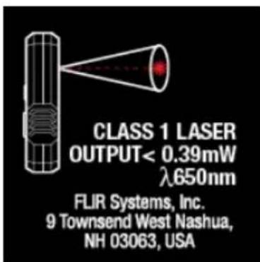
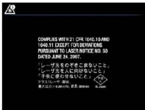
• Refer to the CAUTION statement label (shown below) for critical safety informaon.
Do not use the device in a manner not specified by the manufacturer. This can cause damage to the protecon provided.
 | This symbol, adjacent to another symbol or terminal, indicates that the user must refer to the user manual for further informaon. |
 | This symbol, adjacent to a terminal, indicates that, under normal use, hazardous voltages may be present. |
 | Double insulaon. |

UL lisng is not an indicaon or a vericaon of the accuracy of the meter
3. Introducon
Thank you for selecng the FLIR DM284 True RMS Digital MulMeter with IGM ^TM (Infrared Guide Measurement). The DM284 can measure voltage up to 1000V AC/DC and includes Low-Z (low impedance), VFD (low pass Iter), and oers Smart/Classic Diode modes. This device is shipped fully tested and calibrated and, with proper use, will provide years of reliable service.
3.1 Key Features
- 6000 count 2.8" digital TFT display with bargraph
- Built-in IGM ^TM Infrared imager with laser pointer and crosshair targeng
- Measures Voltage, Current (A, mA, A), Frequency, Resistance/Connuity, Diode (Classic and Smart modes), Capacitance, and Temperature
• Built-in non-contact voltage detector (NCV) - Customizable via easy-to-use menu system
• Automac and Manual ranging - Input over-voltage warning
• MIN-MAX-AVG memory - PEAK MIN and PEAK MAX
- Flex Clamp direct input
- On-screen programming menu navigaon
- Variable-frequency drive VFD mode (low-pass Iter)
- Low-Z (low impedance) mode
- Relave mode
• Data Hold and Auto Hold - Auto Power OFF
• Safety Category Rang: CAT IV-600V, CAT III-1000V. - Equipped with baeries, test leads, alligator clips, test lead storage/holder aachment, Type-K thermocouple, and Quick Start booklet.
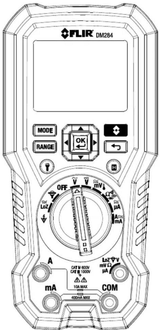
4.1 Front and Back Meter Descripons
Fig. 4-1 Front View
- Work Light and NCV detector area
- LCD Display
- Navigaon/OK buons
- MODE Buon
- RANGE Buon
- Work light Buon
- Rotary Funcon Switch
- Posive (+) Probe Input Jack for A (Current).
- Posive (+) Probe Input Jack for mA (Current).
- COM (-) Probe Input Jack
- Posive (+) Probe Input Jack for all inputs except A and mA
- Display 'Hold' (H) buon
- Cancel/Return Buon
-
IGM ^TM Buon
-
Test Lead holder aachment mounts
- Thermal Imaging lens
- Laser pointer lens
- Lens cover slide control
- Tripod mount (test lead holder aaches here also)
- Tilt Stand (Baery Compartment located beneath the stand)
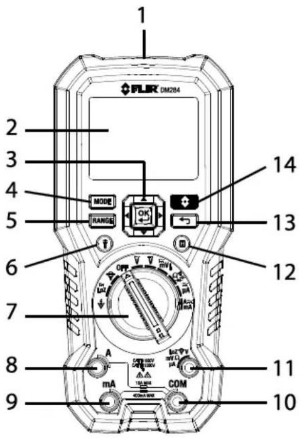
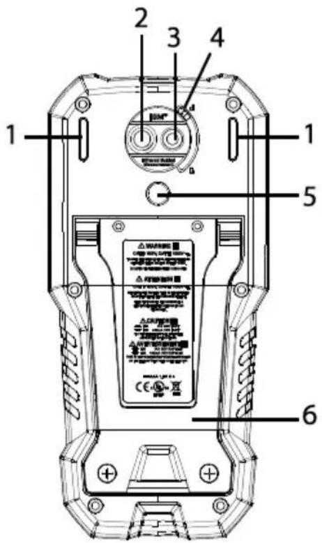
Fig. 4-2 Rear View
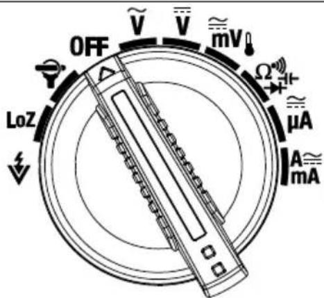
4.2 Funcon Switch Posions
 | Detect AC voltage through the non-contact sensor at the top of the meter. |
 | Measure voltage through the probe inputs with a low-impedance load posioned across the inputs that stabilizes the measurement. |
 | Meter is switched OFF and in full power-saving mode. |
 | FLEX Direct: Auxiliary channel for use with oponal Flexible Current clamp or standard clamp adaptors when >600A measurements are required. In this mode, the meter will display true rms ACA measurements from the connected device. Frequency (Hz) can be displayed by pressing the MODE buon. |
 | Measure AC voltage (V) through the probe inputs. |
 | Measure DC voltage (V) through the probe inputs. |
 | Measure low voltage (mV) through the probe inputs. Use the MODE buon to select AC/DC voltage. |
| [23HZ] | Measure temperature through the probe inputs using a thermocouple adaptor. Use the MODE buon to select Temperature (see Secon 5.2.2, Thermal Sengs Menu, to select °C or °F unit of measure). |
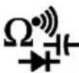 | Measure resistance, connuity, capacitance, or diode through the probe inputs. Use the MODE buon to select the desired funcon. |
 | Measure current through the probe inputs (A or mA). Use the MODE buon to select AC or DC. |
 | Measure μA current through the probe inputs. Use the MODE buon to select AC or DC. |
Fig. 4-3 Funcon Switch
4.3 Funcon Buons and Selector/Navigaon Pad
 | Use to select a sub-funcon of the primary funcon. See Secon 4.3.1, MODE Buon Operaon, for details |
 | From Auto range mode, press to select Manual range mode.From Manual range mode, quick press to change the range (scale). Long press to acvate Auto range mode |
 | Press to acvate the Thermal Camera IGM TM (Infrared Guide Measurement) |
 | Use the selector/navigaon pad to enable extended funconality modes and to navigate mode menu opons |
 | Press to return from a menu screen (no funcon in normal mode). |
 | Press to enter the Hold mode (display hold or auto hold as selected in the Sengs Menu see Secon 5.2.8, Mulmeter sengs Menu) |
 | Press to enable/disable the work light. |
4.3.1 MODE Buon Operaon
| Rotary Switch Posion | Switch Sequence |
| NCV | No operaon |
| LoZ | ACV → DCV → Frequency |
| Flex | ACA → Frequency |
| ACV | ACV → Frequency |
| DCV | No operaon |
| mV (Temperature) | ACmV → DCmV → Frequency → Temperature |
| Resistance | Resistance → Connuity → Capacitance → Diode |
| μA | ACμA → DCμA |
| A (A Terminal) | ACA → DCA → Frequency |
| mA (mA Terminal) | ACmA → DCmA → Frequency |
4.3.2 Selector/Navigaon Pad Operaon
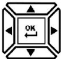
There are ve (5) buons arranged in a square that make up the Selector/Navigaon pad, as shown in Figure 4-4.
flowchart
graph TD
    A["Start"] --> B{OK}
    B --> C["Arrow Up"]
    B --> D["Arrow Down"]
    B --> E["Arrow Left"]
    B --> F["Arrow Right"]
    B --> G["Arrow Left"]
    B --> H["Arrow Up"]
    B --> I["Arrow Down"]
Fig. 4-4 Selector Navigaon Pad
OK buon (center) is used to access the main menu and select/change menu opons.
LEFT/RIGHT buons: The le/right buons are used to navigate the menus.
UP/DOWN buons: The up/down buons are used to navigate the menus.
4.4 Display Icons and Status Indicators
 | Low Impedance mode |
 | Sensed voltage is >30 V (AC or DC) |
 | Non-Contact Voltage detector (low sensitivity mode) for 160~1000V range |
 | Non-Contact Voltage detector (high sensitivity mode) for 80~1000V range |
 | MAX (Maximum) reading value displayed |
 | MIN (Minimum) reading value displayed |
 | AVG (Average) reading value displayed |
 | PEAK MAX value displayed |
 | PEAK MIN value displayed |
 | Auto range mode |
 | Display Hold |
 | Auto Hold |
 | Relave mode |
 | Primary display (large digits) |
 | Secondary display (smaller digits) |
 | Test lead conneccon error |
| ### | Emissivity seng |
 | Baery voltage status |
 | Auto power o funcon enabled |
| ### | AC current or voltage |
| ### | DC current or voltage |
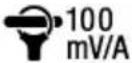 | Flex Clamp Direct Input |
 | Connuity funcon |
 | Diode test funcon |
 | Work light acve |
 | Bar Graph Measurement Indicator |
 | Bar Graph OL (overload) Indicator |
5.1 Using the Opons and Sengs Menus
- Press OK to open the main menu, Use the navigaon pad arrows to step through the menu icons. From le to right, as shown below, they are Image Mode, Thermal Sengs, VFD, Advanced Menu, and Mulmeter Sengs.

- Press OK to open a menu item or to set an opon ON or OFF. When an opon is switched ON, a blue dot will appear next to the menu icon. The navigaon arrows are sometimes used to select an opon.
- Use the Return/Exit buon to exit menu levels and to return to the normal display mode.
- The icons that are available dier in the Mulmeter and IGM ^TM modes. The following informaon will detail this and other menu operaons.
5.2 Opons and Sengs Details
5.2.1 Image Mode Menu

This icon is only available in the IGM ^TM mode. The Image Mode has two sub-menu
selecons: Image + DMM mode
and Image Only mode

- Image + DMM (default opon): Display will show all IR data and DMM data.
- Image Only: Display will show IR data only.
- For both opons, the status bar will show Baery, APO, Work Light, and Laser icons when applicable.
- Image Mode opon is disabled (grayed out) in DMM mode.
Press OK on the Image Mode icon and use the arrows to select IGM + DMM or IMAGE.
5.2.2 Thermal Sengs Menu

The following opons are available in the Thermal Sengs menu. More in-depth informaon may be found in the dedicated IGM secon of this manual.
- IGM Color Palee selecon. Press OK to select one of the display color palees (Iron, Rainbow, or Gray).
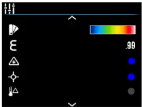
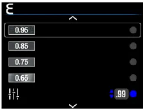
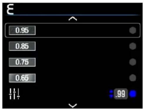
- E Emissivity: Press OK then use the up/down arrows to scroll to the desired
preset (0.95, 0.85, 0.75, 0.65) or to the ne tuning icon. To ne tune, press OK at the ne tuning icon and then use the arrow buons to make a selecon, press OK to conrm. The available range is 0.10 to 0.99 in 0.01 steps.
Laser pointer: Press OK at this icon to switch the laser pointer ON (blue cicle icon) or OFF (empty circle icon).
Cross hairs: Press OK at this icon to switch the cross hairs ON or OFF.
Temperature Dierenal: Only available when you select DMM IGM in the image Mode Menu (above) and mV/Temp on the rotary switch. Press OK to switch this mode ON (blue dot) or OFF. When ON, the display shows the Type Thermocouple temperature and IGM mode temperature dierenal (delta).
5.2.3 VFD Mode VFD
In VFD (variable-frequency drive) mode, high-frequency noise is eliminated from the Mulmeter voltage measurement through the use of a low-pass Iter. VFD mode is available when measuring AC voltage or AC current.
- Press the OK buon to access the menu. Press OK at the VFD icon to select.
- The blue dot next to the icon and the VFD display icon will appear.
- De-select the VFD mode by pressing OK again. The blue dot and VFD display icon will switch OFF when de-selected.
5.2.4 Advanced Menu
Press OK to open the Advanced Menu. Three selecons are available: MAX-MIN-AVG, PEAK, and Relave Mode. The next three seconds cover these features in detail.
5.2.5 MIN-MAX-AVG Mode

This mode is accessed through the Advanced Menu, see previous secon. The meter captures and displays the minimum, maximum, and average readings, updang only when a higher/lower value is registered. The meter also averages the total sum of all recorded values.
Press OK to show the maximum ↑, minimum ↓, and average ◇ readings on the display.
5.2.6 Peak Mode P
This mode is accessed through the Advanced Menu, see above. In Peak mode, the meter captures and displays the positive and negative ACA and ACV peak values. The Peak display values changes only when higher/lower values are registered.
- Press OK to show the Peak Max ↑ and Peak Min ↓ readings on the display.
- Press OK to switch this mode OFF.
5.2.7 Relave mode

This mode is accessed through the Advanced Menu, see above.
- Press OK on this icon to capture a reference reading that subsequent measurements can be compared with.
- A blue dot is shown next to the icon when this mode is selected.
- The reference value will be displayed next to the Relave icon.
- The primary display will show the dience between the measured value and the stored reference.
- Press OK at this icon to switch the Relave mode OFF.
5.2.8 Mulmeter Sengs Menu

- Press OK to open the main menu
-
Navigate to the Mulmeter Sengs icon using the arrow buons
-
Open the Sengs menu by pressing the OK buon.
-
See the Sengs menu example below. The items in the example may dier from the meter that you have depending on the rmware version. Customize the sengs as described below:
- Diode ➞ (Smart or Classic modes); see Secon 7.11, Classic Diode, and Secon 7.12, Smart Diode. Use the OK buon to choose the desired seng.
• Auto power o (APO): Press OK to open the sub-menu. Use the arrow buons to choose the me period aer which the meter enters sleep mode. Press OK to conrm the selecon (a blue dot will appear next to the selecon).
• Auto hold: Use the OK buon to toggle ON (blue dot) and OFF. For more informaon, see Secon 7.4, Data Hold and Auto Hold.
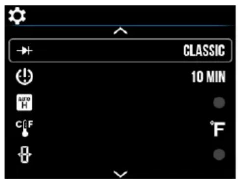
• CIEF Temperature units. Use the OK buon to toggle °C and °F.
- Coarse Resoluon (C.r. ON/OFF). Use the OK buon to toggle ON (blue dot) and OFF. This funcon is for Voltage funcon only. The range and resoluon for the Voltage funcon will change as follows when Coarse Resoluon is enabled:
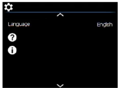
• Language: Scroll to the desired language and press OK.
• Help Screen: View the FLIR Customer Care contact informaon.
• Informaon: View DMM, IGM, and Laser technical informaon.


6. Meter Power
6.1 Powering the Meter
- Set the funcon switch to any posion to switch on the meter.
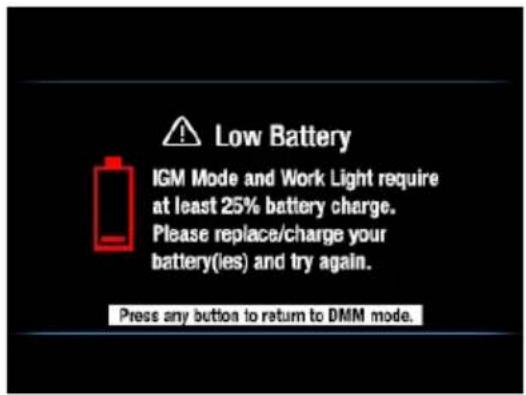
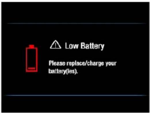
- If the baery indicator shows that the baery voltage is low, if one of the Low Baery screens appears (shown below), or if the meter does not power on, replace the baeries. See Secon 9.2, Baery Replacement. If using the Model TA04 charging system, please recharge the rechargeable baery.
6.2 Auto Power OFF (APO)
The meter enters sleep mode aer a programmable period of inactivity, to customize this seng please see Secon 5.2.8, Mulmeter Sengs Menu. The default me-out is 10 minutes. The me can be set from 1 \~ 10 minutes (select OFF to disable the APO). 20 seconds prior to entering APO mode, the meter beeps; at this point, press any buon or turn the Rotary Switch to reset the APO mer.
7. MulMeter Operaon
Cauon: Before operang the device, you must read, understand, and follow all instrucons, dangers, warnings, cauons, and notes.
Cauon: When the meter is not in use, the funcon switch should be set to the OFF posion.
Cauon: When connecng the probe leads to the device under test, connect the COM (negave) lead before connecng the posive lead. When removing the probe leads, remove the posive lead before removing the COM (negave) lead.
7.1 Auto/Manual Range Mode
In Auto range mode, the meter automacally selects the most appropriate measurement scale. In Manual range mode, the desired range (scale) can be adjusted by the user. Auto range mode is the default mode of operaon. When a new funcon is selected with the funcon switch, the starng mode is Auto range and the indicator is displayed.
- To enter Manual range mode, short press the RANGE buon. To change the range, press the flown repeatedly unl the desired range is displayed.
- To return to the Auto range mode, long press the RANGE buon unl the Auto Range indicator is again displayed.
7.2 Probe Connecon Alert
For current measurements, when the probe leads are not plugged into the correct jacks for the measurement selected by the funcon switch, the probe display alert 'PROBE' is shown.
7.3 Out of Range Warning (OL)
If the input is over/under the full-scale range in Manual range mode, or if the signal has exceeded the maximum/minimum input in Auto range mode, 'OL' is displayed.
7.4 Data Hold and Auto Hold
The meter has two HOLD modes: classic Data Hold and Auto Hold. To select Data Hold or Auto Hold as the default, please use the Sengs menu (see Secon 5.2.8, Mulmeter Sengs Menu). Refer to the paragraphs below for instrucons on using the Hold modes.
7.4.1 Data Hold Mode
In Data Hold mode, the primary meter display freezes the last reading. To enter/exit Data Hold mode, press the ☐ on. In Hold mode, the indicator is displayed.
7.4.2 Auto Hold Mode
In Auto hold mode, the secondary display freezes the last reading and the Hicon is displayed. The real-me reading is displayed on the primary display.
The held reading will not change unless the dience between the held reading and any new reading is > 50 digits.
The Auto hold funcon will capture a reading if the reading is >1% full scale (trigger level) for Voltage, Current, and Capacitance. For Resistance, Diode, and Temperature the trigger is acve as long as OL (over range).
To enter/exit Auto hold mode, press the 📄budn.
7.5 Status Bar and Menu Icons
The Status Bar is located at the top of the display and separated into two groups: Right and Le side groups.
The Right side group is located at the top right of the display. The icons are shown below, in Secon 4, Meter Descripon and Reference, and other relevant areas of this manual when applicable.

- Auto Hold
- Data Hold
- Auto Range
- VFD mode
- Low Impedance mode
- Work light
• Auto Power OFF (APO) - Baery status
The Le side group is located at the top le of the display. The icons are shown below and other relevant areas of this manual when applicable.
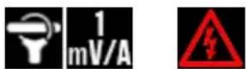
• FLEX Clamp Adaptor icon
• FLEX Clamp Adaptor range
• Hazardous voltages present icon
There are 5 main opons in the Menu bar. These are explained in some detail in Secon 5, Opons and Sengs Menus.

○ Image Mode (available in IGM ^TM mode only)
○ Thermal Sengs (available in IGM ^TM mode only)
○ VFD (low pass Iter)
- Advanced Features Menu
- Mulmeter Sengs
- Use the Le / Right buon to move the cursor
- Press the OK buon to select an onpon.
- Up / Down buons are not used for Menu bar operaon.
- If an opon is disabled (grayed) it is not available for the currently acve mode.
7.6 Test Lead Holder Accessory
If desired, connect the supplied Test Lead Holder to the rear of the meter. The Test Lead Holder connects to the back of the meter (to items 1 and 5 as shown in Fig. 4-2 in Secon 4, Meter Descripon and Reference Guide).
7.7 Voltage and Frequency Measurements
-
Set the funcon switch to one of the following posions:
-
(VDC) or (VAC) for high voltage measurements.
- mV (milli-volts) for low voltage measurements (use MODE to select AC or DC).
-
LoZ for voltage measurements using the meter's low input impedance mode.
The LoZ indicator will be displayed (use MODE to select AC or DC). -
Insert the black probe lead into the negave COM terminal and the red probe lead into the posive terminal.
-
For mV and LoZ measurements use the MODE buon to select AC or DC measurement:
-
The indicator will be displayed for AC measurements.
-
The indicator will be displayed for DC measurements.
-
Connect the probe leads in parallel to the part under test.
-
Read the voltage value on the display.
-
The Frequency (Hz) of the measured voltage is shown on the smaller, secondary display digits above the primary voltage reading. Press the N05n to view only the Frequency reading.
-
Refer to Secon 5, Opons and Sengs Menus, for customizing the meter and using the VFD, MIN-MAX-AVG, Peak, and Relave modes of operaon.
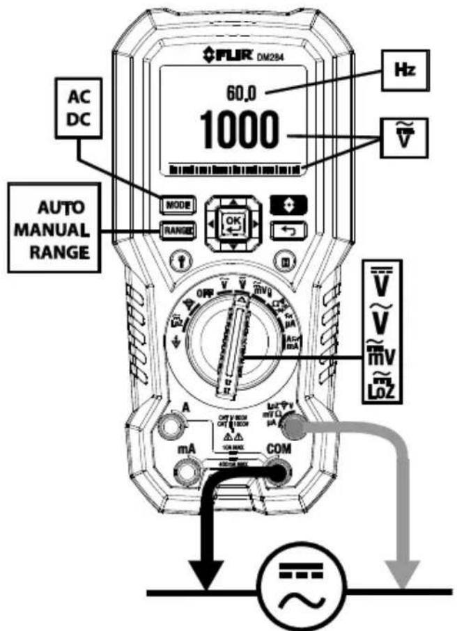
Fig. 7-1 Voltage and Frequency Measurements
7.8 Non-Contact Voltage Detector
- Set the funcon switch to the NCV posion. See Figure 7-2.
- Be sure to remove the test leads from the meter when doing NCV tests.
- Use the RANGE buon to choose High (80\~1000V) or Low (160\~1000V) Sensitivity mode.
- Posion the top of the meter close to a source of voltage or electromagnec eld.
- When a voltage or electromagnec eld is detected the meter will emit a connuous tone and the displayed NCV icon will turn red in color and blink.
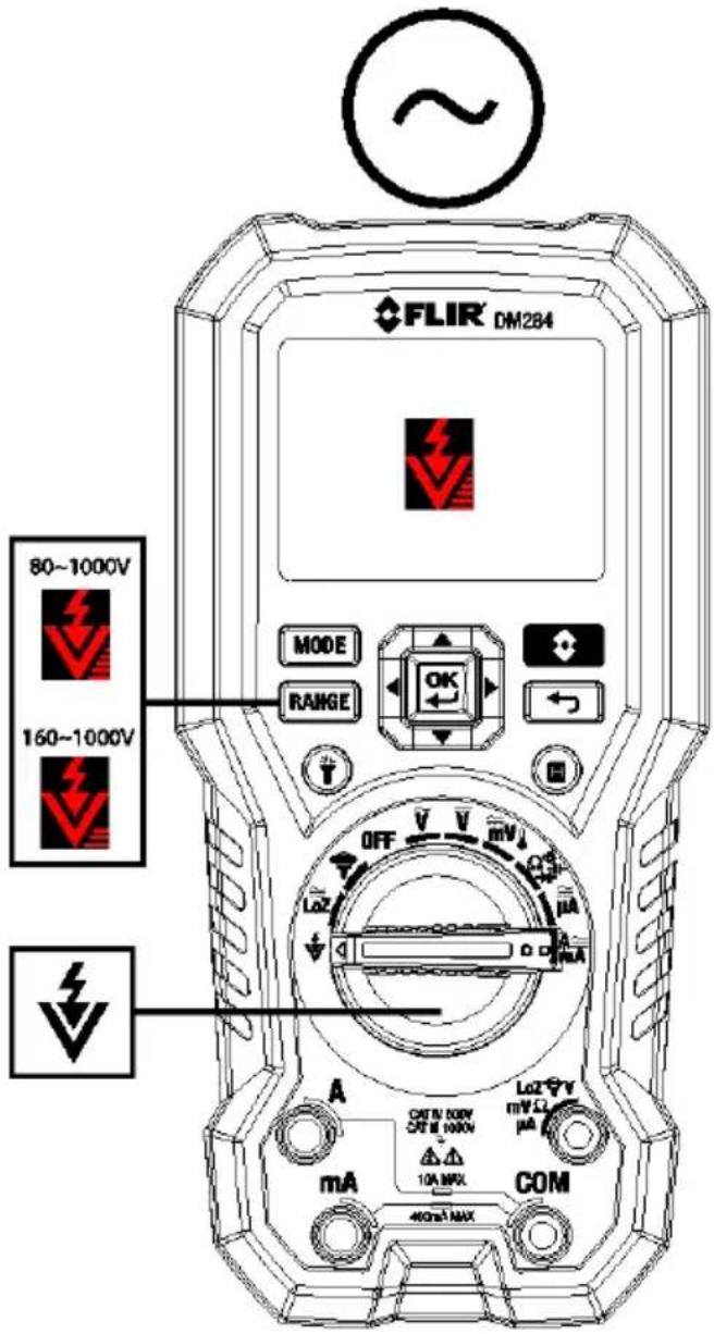
Fig. 7-2 Non-Contact Voltage Detector
7.9 Resistance Measurements
Warning: Do not perform diode, resistance or connuity tests before removing power from capacitors and other devices under test during a measurement. Injury to persons can occur.
- Refer to Fig. 7-3. Set the funcon switch to the posion.
- Use MODE to step to the Ω display if necessary.
- Insert the black probe lead into the negave COM terminal and the red probe lead into the positive terminal.
- Touch the ps of the probe across the circuit or component under test.
- Read the resistance value on the display.
- Refer to Secon 5, Opons and Sengs Menus, for customizing the meter and using the MIN-MAX-AVG and Relave modes of operaon.
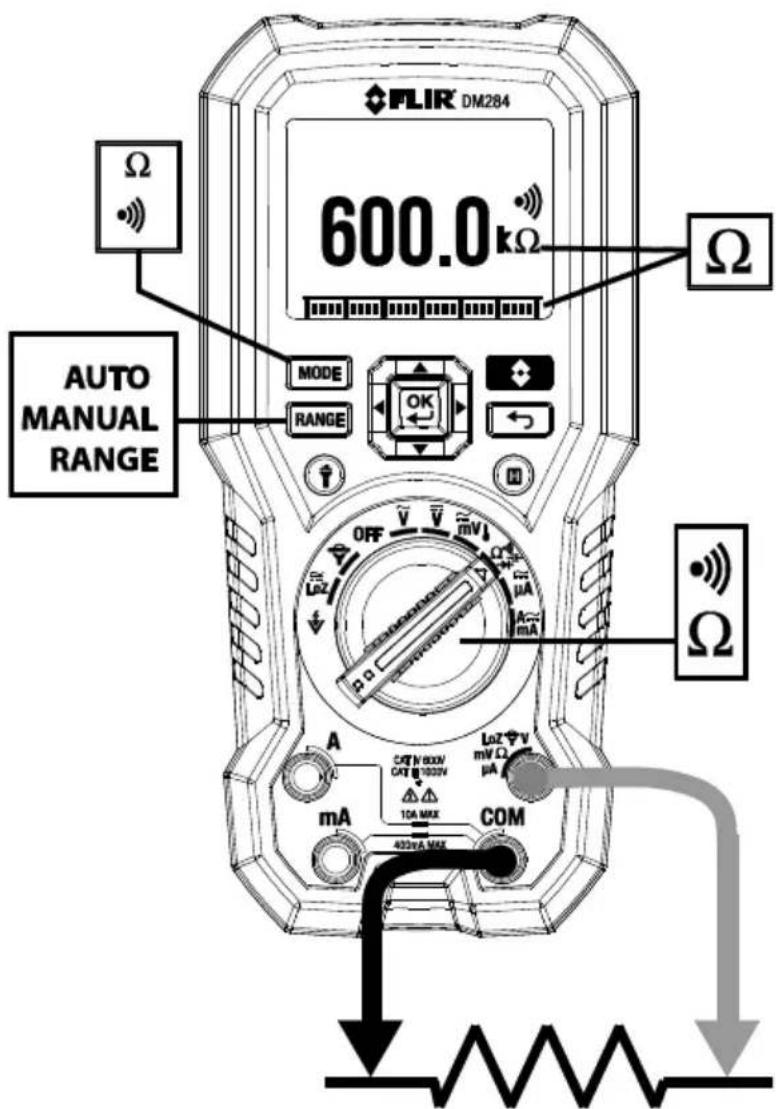
Fig. 7-3 Resistance and Connuity Measurements
7.10 Connuity Test
Warning: Do not perform diode, resistance or connuity tests before removing the power from capacitors and other devices under test during a measurement. Injury to persons can occur.
- Refer to Fig. 7-3. Set the funcon switch to the position.
- Use the MODE buon to select connuity. The indicator will be displayed.
- Insert the black probe lead into the negave COM terminal and the red probe lead into the positive terminal.
- Touch the ps of the probe across the circuit or component under test.
- If the resistance is <20 the meter beeps. If the resistance is >200 the meter will not beep. >20 but <200 the beeping will stop at an unspecified point.
7.11 Classic Diode Test
Warning: Do not perform diode tests before removing the power to the diode or other devices under test during a measurement. Injury to persons can occur.
- If not already selected, choose CLASSIC Diode test mode in the Sengs menu (Secon 5.2.8, Mulmeter Sengs Menu).
- Set the funcon switch to the diode posion. Use the MODE buon to select the diode test funcon. The diode indicator will be displayed.
- Insert the black probe lead into the negave COM terminal and the red probe lead into the posive terminal.
- Touch the ps of the probe across the diode or semiconductor juncon under test in one polarity (direcon) and then in the opposite polarity as shown in Fig. 7-4.
- If the reading is between 0.400 and 0.800V in one direcon and OL (overload) in the opposite direcon, the component is good. If the measurement is 0V in both direcons (shorted) or OL in both direcons (open), the component is bad.
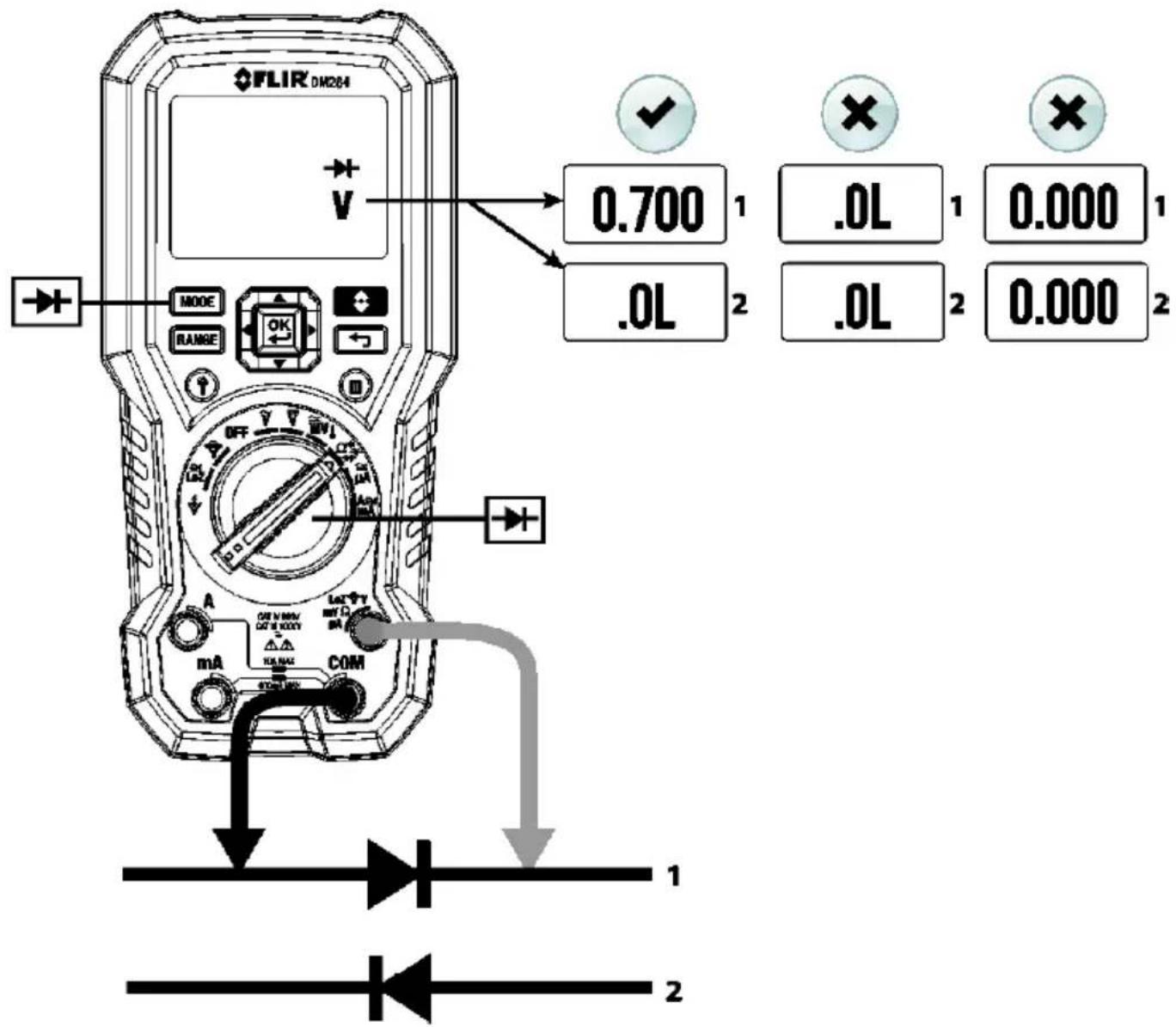
Fig. 7-4 Classic Diode Test
7.12 Smart Diode Test
Warning: Do not perform diode tests before removing the power from capacitors and other devices under test during a measurement. Injury to persons can occur.
- If not already selected, choose SMART Diode test mode in the Mulmeter Sengs menu (Secon 5.2.8, Mulmeter Sengs Menu).
- Set the funcon switch to the diode ^m position. Use the MODE buon to select the diode test funcon. The diode indicator will be displayed.
- Insert the black probe lead into the negave COM terminal and the red probe lead into the positive terminal.
- Touch the ps of the probe across the diode or semiconductor juncon under test.
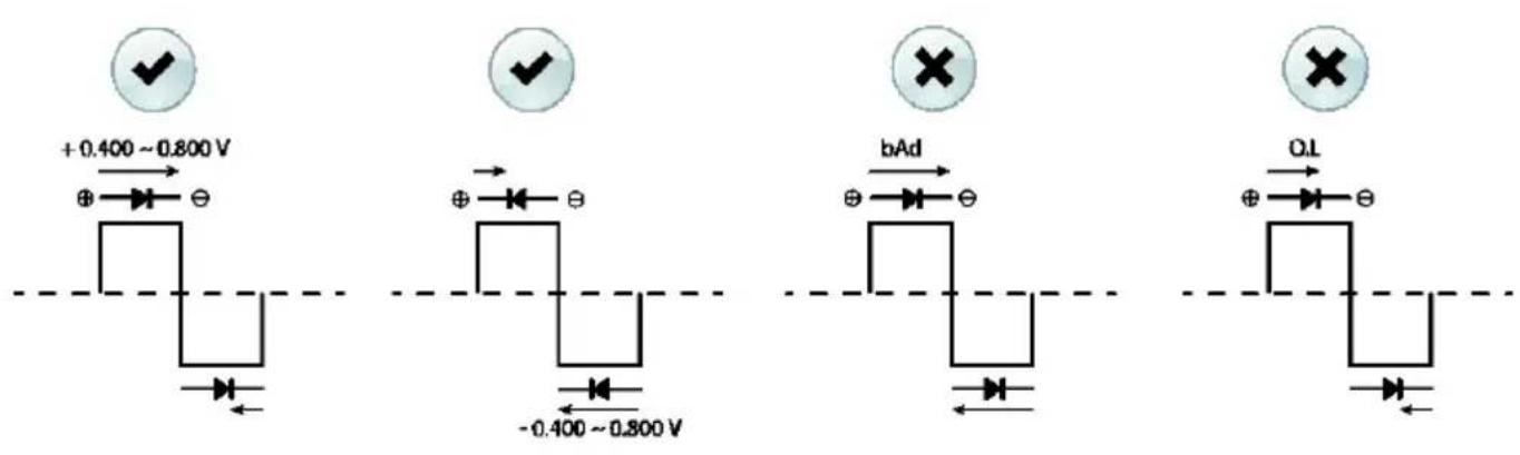
- If the reading is between ± 0.400 0.800V , the component is good; BAD or O.L displays indicate a defective component.
NOTES: In SMART Diode mode the meter checks diodes using an alternang test signal sent through the diode in both direcons. This allows the user to check the diode without having to reverse polarity manually. The meter display will show ±0.4000.800V for a good diode, ‘BAD’ for a shorted diode, and ‘O.L’ for an opened diode. See Fig. 7-5 below:
Fig. 7-5 SMART Diode Test
7.13 Capacitance Measurements
Warning: Do not perform capacitance tests before removing power to the capacitor or other devices under test during a measurement. Injury to persons can occur.
- Set the funcon switch to the position.
- Use the MODE buon to select the capacitance measurement. The F (Farad) unit of measure will be displayed.
- Insert the black probe lead into the negave COM terminal and the red probe lead into the positive terminal.
- Touch the ps of the probe across the part under test.
- Read the capacitance value on the display.
- Refer to Secon 5, Opons and Sengs Menus, for customizing the meter and using the MIN-MAX-AVG and Relave modes of operaon.
Note: For very large capacitance values, it may take several minutes for the measurement to sele and the nal reading to stabilize.
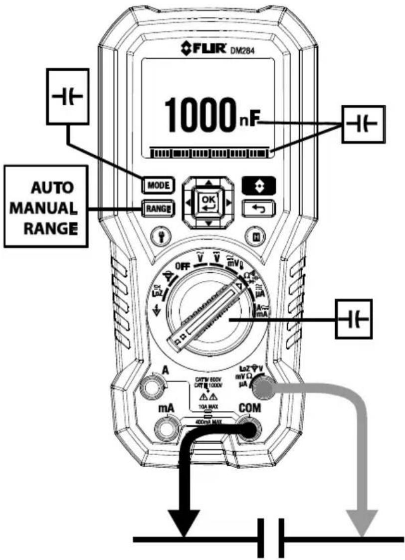
Fig. 7-6 Capacitance Measurements
7.14 Type K Temperature Measurements
- Set the funcon to the Temperature p vision .
- Use the MODE buon to select temperature measurement. The °F or °C unit will be displayed. To change from F to C or from C to F, please use the Mulmeter Sengs menu (Secon 5.2.8, Mulmeter Sengs Menu).
- While observing the polarity, insert the thermocouple adapter into the negave COM terminal and the posive terminal.
- Touch the p of the thermocouple to the part under test. Keep the thermocouple p on the part unl the reading stabilizes.
- Read the temperature value on the display.
- To avoid electrical shock, disconnect the thermocouple adapter before turning the funcon switch to another posion.
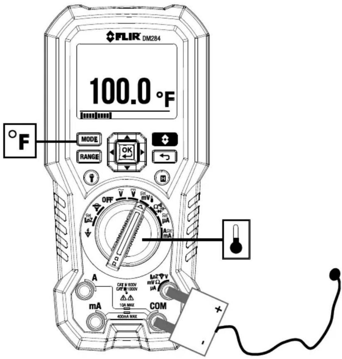
Fig. 7-7 Temperature Measurements
7.15 Current and Frequency Measurements (A, mA, A)
For test lead current measurements, disconnect the part under test and connect the test leads in series with the part, see Figure 7-8.
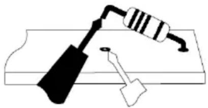
natural_image
Simple line drawing of a resistor and hammer on a base (no text or symbols)Fig. 7-8 Disconnected component
7.15.1 Test Lead Current Measurements (A, mA, and A)
- For test lead measurements (A, mA, and A), set the funcon switch to the or posion.

- Insert the black probe lead into the negave COM terminal and the red probe lead into one of the following positive terminals:
• A for high current measurements.
- mA for lower current measurements.
- A for micro-amp measurements
-
Use the button to select AC or DC measurement.
-
The indicator will be displayed for AC measurements.
-
The indicator will be displayed for DC measurements.
-
Connect the probe leads in series with the part in accordance with Fig. 7-8 and Fig. 7-9 for 'A' measurements, Fig. 7-10 for mA measurements, or Fig. 7-11 for A measurements.
-
Read the current and frequency values on the display. Frequency (Hz) is available only in the A AC and mA AC modes. Use the MODE view the Frequency only.
-
Refer to Secon 5, Opons and Sengs Menus, for customizing the meter and using the VFD, MIN-MAX-AVG, Peak, and Relave modes of operaon.
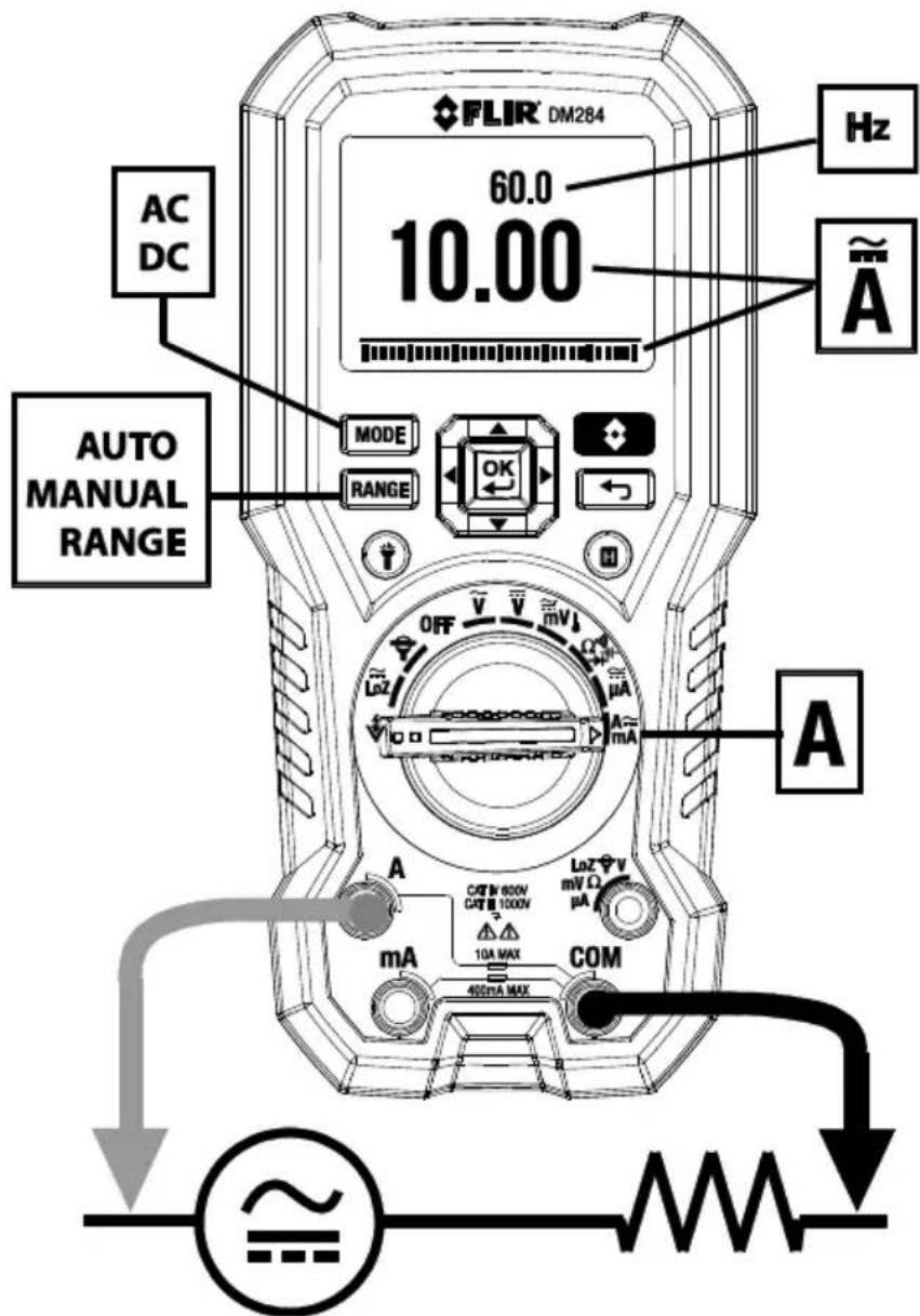
Fig. 7-9 High Current 'A' Measurements
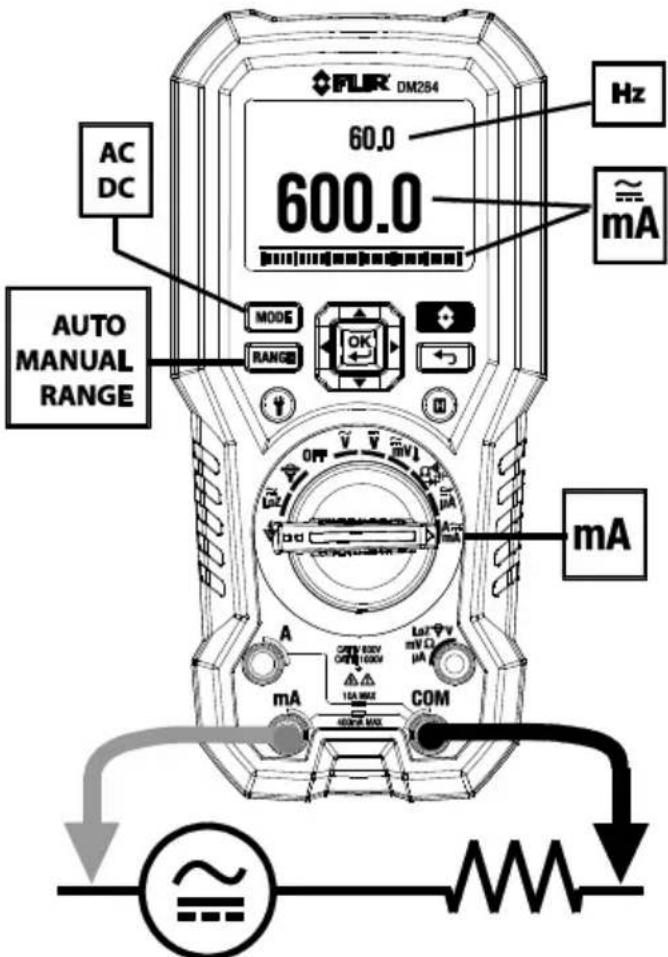
Fig. 7-10 mA Current Measurements
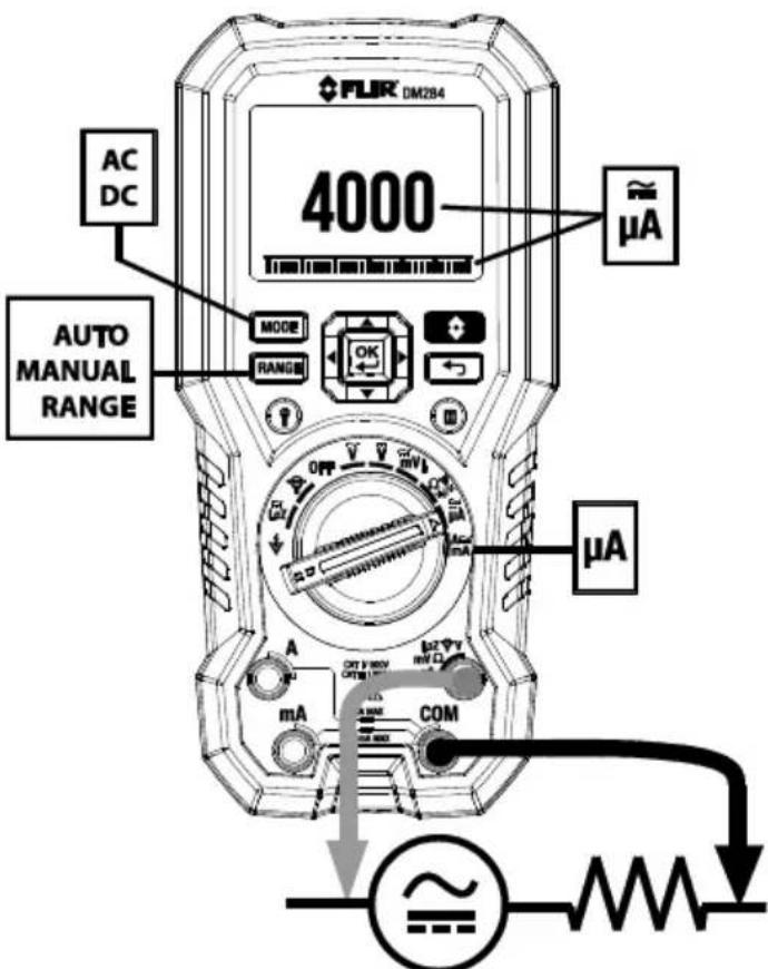
Fig. 7-11 uA Current Measurements
7.15.2 FLEX Clamp Adaptor Current and Frequency Measurements
FLIR Flex Clamp Adaptors (Models TA72 and TA74, for example) and other clamp adaptors can be connected to the DM284 to display current measurements made by a clamp adaptor.
- Turn the funcon dial to the pesion.
- Connect a Clamp adaptor as shown in Fig. 7-12.
- Set the Range of the Flex Clamp Adaptor to match the range of the DM284.
- Use the RANGE buon to select the range of the DM284 (1, 10, 100 mv/A). The selected range will be shown on the right side of the DM284 display.
- Operate the Flex Clamp per instrucons provided with the Flex Clamp meter.
- Read the current measured by the Flex Clamp on the DM284 LCD. The frequency is also shown on the DM284's secondary display.
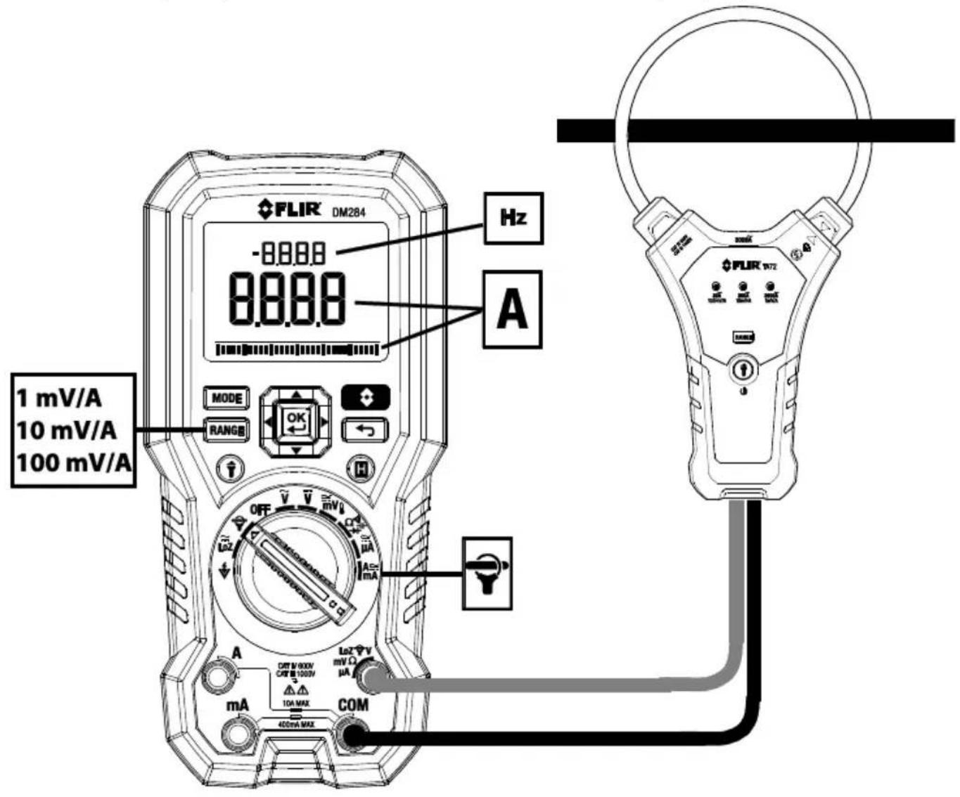
Fig. 7-12 FLEX Clamp Applicaon
8.1 Thermal Camera IGM™ Basics
In the Thermal Imaging mode, the user can measure a targeted surface's temperature. This is accomplished by detecting the energy emitted by the surface under test. A thermal image of the area under test is viewed in the same manner as with dedicated thermal imaging devices, where color variaons react temperature variaons. See Secon 8.7, Infrared Energy and Thermal Imaging Theory for in-depth informaon. The laser pointer and display cross hairs assist in targeng.
- Press the IGM buon to open the Thermal Imager. In Fig 8-1 the meter is set to color palee IRON. Select other palees in the Thermal Sengs Menu.
- Open the protecve lens cover on the back of the meter. The protecve lens cover can easily be slid up (open) or down (closed) by hand. See Secon 4, Meter Descripon and Reference Guide for exact posion of rear cover.
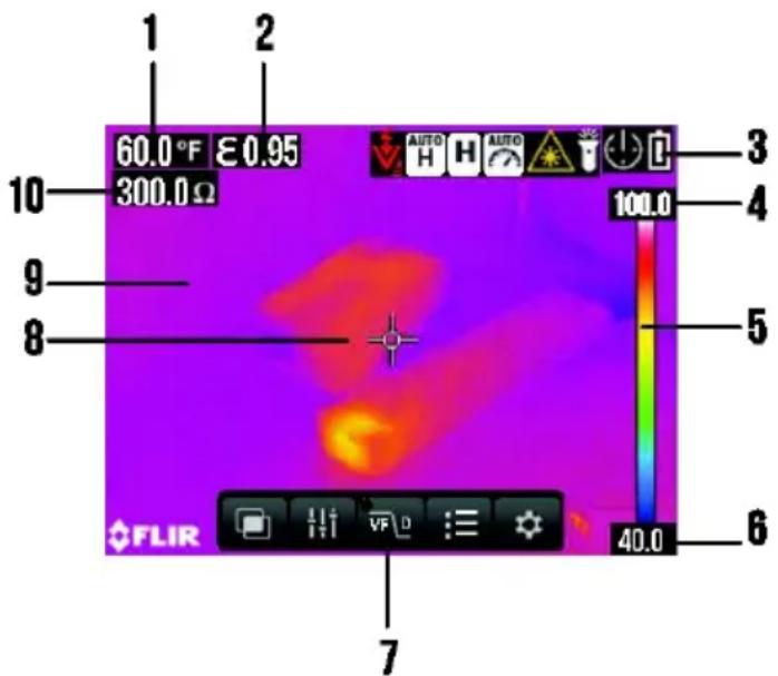
Fig. 8-1 IGM Display Example
-
IGM Temperature measurement represents the temperature of the spot sensed. Note that while the temperature reading is stabilizing dashes will be displayed temporarily.
-
The currently selected Emissivity ( ) value. Use the Thermal Sengs Menu to change the emissivity seng. See Secon 8.6, Emissivity Factors for Common Materials.
-
Status Bar Icon area
-
Highest reading measured in the current frame
-
The Thermal scale shows the range of colors for thermal images. The lighter the color, the warmer the temperature; the darker the color, the cooler the temperature.
-
Lowest reading measured in the current frame.
-
Menu Bar area
-
Cross hairs for surface targeng.
-
Thermal image frame
-
DMM measurement is shown below the temperature measurement. Set the meter to show Mulmeter readings superimposed on the image in the Image Mode menu.
To customize the Thermal Imager, refer to Secon 5.2.2, Thermal Sengs Menu. For basic operaon follow these steps:
- Set the funcon switch to any posion.
-
Press the IGM buon to switch the IGM Thermal Imager ON. Point the thermal imaging lens (located on the rear of the meter) toward an area to measure.
-
The display will show the temperature measurement in the upper le hand corner for the targeted area along with the currently selected emissivity value.
-
In the Thermal Imaging mode, the laser pointer and display cross hairs can be used to assist in targeng. These tools can be switched ON or OFF in the Thermal Sengs Menu.
-
In the Thermal imaging mode, the meter connues to operate normally as a Mulmeter allowing any of the electrical funcons to be used. Note that in the Thermal Imaging mode the electrical funcons are shown on the le side of the display and can be switched o if desired in the Image Mode menu.
-
The Distance to Spot rao for the imager is 30:1 meaning that the measurement spot is 30 mes smaller than the distance from meter to spot (at a distance of 30", the meter 'sees' a target spot of 1"). See Fig. 8-2.
-
The thermal imager's FOV (Field of View) is 50 degrees (top view) and 38.6 degrees (side view), see Fig. 8-3 (a) and (b).
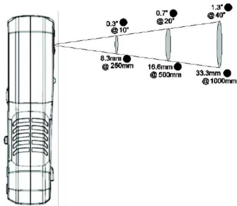
Fig. 8-2 Distance-to-Spot rao 30:1
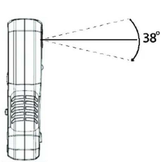
Fig. 8-3 (a) Field of View – side view
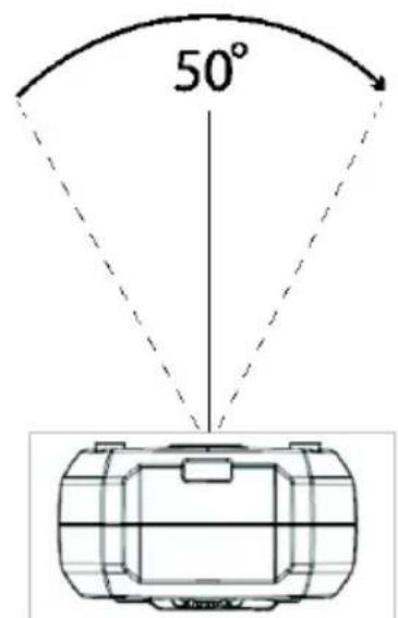
Fig. 8-3 (b) Field of View - top view
8.2 Thermal Sengs Menu
i!i
Press OK to open the main menu and then press OK on the Thermal Sengs icon. See the Thermal Sengs screenshot example and descripons below.
- IGM Color Palee selecon. Press OK to select one of the display color palees (Iron, Rainbow, or Gray).
- Emissivity: Press OK then use the up/down arrows to scroll to the desired preset (0.95, 0.85, 0.75, 0.65) and press OK. To ne tune, press OK at the ne tuning icon (located below the presets) and then use the arrow buons to make a selecon. The available range is 0.10 to 0.99 in 0.01 steps.
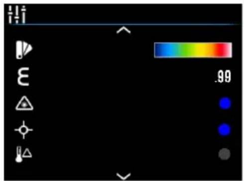
- Laser pointer: Press OK at this icon to switch the laser pointer ON (blue dot next to icon) or OFF.
• Cross hairs: Press OK at this icon to switch the IGM target cross hairs ON or OFF.
- Temperature Dierenal: Thermocouple temperature minus IGM temperature. Only available when Image + DMM is selected in the Image Mode Menu (see next secon) and mV/Temp is selected with the rotary switch. Press OK to switch this mode ON or OFF.
In Fig. 8-4, the 3^rd row shows a dierenal temperature of 5.0 °F (IGM temperature is 85.0°F and the Type-K temperature is 80.0°F in the example). See Secon 7.14, Type-K Temperature Measurements for Type-K measurements.
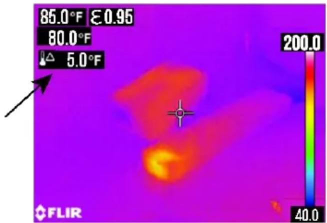
Fig. 8-4 Type-K / IGM Temperature Dierenal Reading Example
8.3 Image Mode Menu

Press OK to open the Main menu and then press OK on the Image Mode icon. Select Image + DMM mode or Image Only mode from the Image Mode menu using the arrow buons.
- Image + DMM (default mode): Display will show all IR data and DMM data.
- Image Only: Display will show IR data only.
- For both opons, the status bar will show Baery, APO, Work Light, and Laser icons when applicable.
8.4 Status Bar Display Icons
The Status Bar is located at the top-right corner. There are 2 rows of icons as shown. The icons are always on the right side of the display and in the same sequence. From top le to right these Status Bar icons are: Auto Hold, Data Hold, Auto Range, Laser Pointer, Work light, APO, baery status, VFD, FLEX clamp input/range, and Low Impedance mode (LoZ). For details on these, please refer to Secon 4, Meter Descripon and Reference Guide and Secon 7, Mulmeter Operaon.
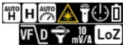
To customize the display layout please refer to Secon 5, Sengs and Opons Menus.
8.5 Using the Mulmeter in the IGM ^TM mode
The Mulmeter can be used as described in Secon 7, Mulmeter Operaon while the IGM™ mode is acve. Mulmeter readings, status bar icons, and operaonal modes such as PEAK, RELATIVE, and MIN-MAX-AVG can be viewed directly on top of the thermal image when IMAGE + DMM mode is selected in the Image Mode menu (see Secon 5.2.1, Image Mode Menu).
8.6 Emissivity Factors for Common Materials
| Material | Emissivity | Material | Emissivity |
| Asphalt | 0.90 to 0.98 | Cloth (black) | 0.98 |
| Concrete | 0.94 | Skin (human) | 0.98 |
| Cement | 0.96 | Leather | 0.75 to 0.80 |
| Sand | 0.90 | Charcoal (powder) | 0.96 |
| Soil | 0.92 to 0.96 | Lacquer | 0.80 to 0.95 |
| Water | 0.92 to 0.96 | Lacquer (ma) | 0.97 |
| Ice | 0.96 to 0.98 | Rubber (black) | 0.94 |
| Snow | 0.83 | Plasc | 0.85 to 0.95 |
| Glass | 0.90 to 0.95 | Timber | 0.90 |
| Ceramic | 0.90 to 0.94 | Paper | 0.70 to 0.94 |
| Marble | 0.94 | Chromium Oxides | 0.81 |
| Plaster | 0.80 to 0.90 | Copper Oxides | 0.78 |
| Mortar | 0.89 to 0.91 | Iron Oxides | 0.78 to 0.82 |
| Brick | 0.93 to 0.96 | Texles | 0.90 |
8.7 Infrared Energy and Thermal Imaging Overview
A thermal imager generates an image based on temperature dierences. In a thermal image the hoest item in the scene appears as white and the coldest item as black, and all other items are represented as a gray scale value between white and black.
It may take some me to get used to the thermal imagery. Having a basic understanding of the dierences between thermal and daylight cameras can help with geng the best performance from the DM284.
One dience between thermal and daylight cameras has to do with where the energy comes from to create an image. When viewing an image with an ordinary camera, there has to be some source of visible light (something hot, such as the sun or lights) that reects o of the objects in the scene to the camera. The same is true with human eyesight; the vast majority of what people see is based on reected light energy. On the other hand, the thermal imager detects energy that is directly radiated from objects in the scene.
This is why hot objects such as parts on an engines and exhaust pipes appear white, while the sky, puddles of water and other cold objects appear dark (or cool). Scenes with familiar objects will be easy to interpret with some experience.
Infrared energy is part of a complete range of radiaon called the electromagnec spectrum. The electromagnec spectrum includes gamma rays, X-rays, ultraviolet, visible, infrared, microwaves (RADAR), and radio waves. The only dience is their wavelength or frequency. All of these forms of radiaon travel at the speed of light. Infrared radiaon lies between the visible and RADAR porons of the electromagnec spectrum.
The primary source of infrared radiaon is heat or thermal radiaon. Any object that has a temperature radiates in the infrared poron of the electromagnec spectrum. Even objects that are very cold, such as an ice cube, emit infrared. When an object is not quite hot enough to radiate visible light, it will emit most of its energy in the infrared. For example, hot charcoal may not give o light, but it does emit infrared radiaon, which we feel as heat. The warmer the object, the more infrared radiaon it emits.
Infrared imaging devices produce an image of invisible infrared or “heat” radiaon that is unseen by the human eye. There are no colors or “shades” of gray in infrared, only varying intensities of radiated energy. The infrared imager converts this energy into an image that we can interpret.
The Infrared Training center oers training (including online training) and cercaon in all aspects of thermography: hp://www.infraredtraining.com/.
9.1 Cleaning and Storage
Wipe the housing with a damp cloth as needed. Use a high quality lens wipe to remove dirt or smudges from the meter lenses and display window. Please do not use abrasives or solvents to clean the meter housing, lenses, or display window.
If the meter is not to be used for an extended period, remove the baeries and store them separately.
9.2 Baery Replacement
The Baery symbol ashes with no 'bars' when the baeries have reached a crical level. The meter displays readings within specicaons while the low baery indicator is on. The meter powers o before it displays an out of tolerance reading.
WARNING: To avoid electrical shock, disconnect the meter from any connected circuits, remove the test leads from the meter terminals, and set the funcon switch to the OFF posion before aempng to replace the baeries.
- Unscrew and remove the baery compartment cover.
- Replace the four (4) standard AAA baeries, observing correct polarity.
- If using the Model TA04 rechargeable lithium polymer battery system, please recharge the rechargeable baery.
- Secure the baery compartment cover.
9.3 Fuse Replacement
The two fuses are accessed via the baery compartment. The fuses are rated:
- mA: 440 mA, 1000 V IR 10 kA fuse (Bussmann DMM-B-44/100).
• A: 11 A, 1000 V IR 20 kA fuse (Bussmann DMM-B-11A). - Fuse kit PN: FS881, contains one of each fuse type.
9.4 Disposal of Electronic Waste
As with most electronic products, this equipment must be disposed of in an environmentally friendly way, and in accordance with exisng regulaons for electronic waste. Please contact your FLIR Systems representave for more details.
10.1 General specicaons
Maximum voltage: 1000 V DC or 1000 V AC RMS
Display Counts: 6000
Polarity Indication: Automatic, positive implied, negative indicated
Over-range Indication: OL
Measuring Rate: 3 samples per second
Power Requirements: 4 x 1.5 V AAA alkaline or lithium batteries or optional Model TA04 lithium polymer rechargeable battery system
- Battery Type: Alkaline 'AAA' Battery x 4
○ Battery Life: approximately 9 hours (DMM) or 2 hours (IGM) - Battery Type Energizer L92 Ultimate Lithium 'AAA' Battery x 4
○ Battery Life: approximately 11.5 hours (DMM) or 5.5 hours (IGM) - Optional Rechargeable Battery Type: 3000mA Li-Polymer FLIR PN: TA04-KIT
○ Battery Life: approximately 30 hours (DMM) or 12 hours (IGM)
Auto Power Off: Default 20 minutes
Operating Temp/RH: 14°F to 86°F (-10°C to 30°C), < 85% RH
86°F to 104°F (30°C to 40°C), < 75% RH
104°F to 122°F (40°C to 50°C), <45% RH
Storage Temperature/RH: -4°F to 140°F (-20°C to 60°C), 0-80% RH (without batteries)
Temperature Coefficient: 0.1 x (specified accuracy)/°F, < 64.4°F (18°C), >82.4°F (28°C)
Operating Altitude: 6560' (2000m)
Calibration Cycle: One year
Weight: 18.9 oz. (537g)
Dimensions: (L x W x H) 7.9 x 3.7 x 1.9 in. (200 x 95 x 49mm)
Safety: Complies with IEC 61010-1 CAT IV-600 V, CAT III-1000V
| CAT | Application Field |
| I | Circuits not connected to mains. |
| II | Circuits directly connected to a low-voltage installation. |
| III | Building installation. |
| IV | Source of the low-voltage installation. |
EMC: EN 61326-1
Pollution degree: 2
Drop protection: 3m (9.8')
Max. Operating Altitude: 2000m (6562 ft.)
Vibration: Random Vibration per MILPRF28800F Class 2
10.2 Thermal Imaging Specicaons
IR Temperature Range 14 \~ 302°F (-10 \~ 150°C)
IR Temperature Resolution 0.1°F/C
Image Sensitivity < or equal to 150mK (0.15°C)
IR Temperature Accuracy 3°C or 3% whichever is greater (>77°F [25°C]) or 9°F (5°C)
(14\~77°F [-10 to 25°C])
Emissivity 0.95 maximum (4 presets and a fine tuning feature)
Distance to Spot ratio 30:1
Response time 150ms
Spectral Response 8\~14um
Scanning type Continuous
Repeatability 0.5%
Image Detector Lepton
Field of View (FOV) 120 x 160 pixels (50 °)
Color Palettes Iron, Rainbow, and Greyscale
Laser type Class 1
Laser power < 0.4mW
10.3 Electrical Specicaons
Accuracy is given as ± (% of reading + counts of least significant digit) at 73.4^ ± 9^ ( 23^ ± 5^ ), with relative humidity < 80%
Temperature coefficient: 0.1 * (Specified accuracy) / °F, < 64.4°F (18°C), > 82.4°F (28°C)
AC Function notes:
- ACV and ACA are ac coupled, true RMS.
- For all AC functions, LCD displays 0 counts when the reading < 10 counts.
- For square waves, accuracy is unspecified.
- For non-sinusoidal waveforms, additional accuracy for Crest Factor (C.F.):
○ Add 1.0% for C.F. 1.0 to 2.0
- Add 2.5% for C.F. 2.0 to 2.5
- Add 4.0% for C.F. 2.5 to 3.0
• Max. Crest Factor of Input Signal:
- 3.0 @ 3000 counts
- 2.0 @ 4500 counts
- 1.5 @ 6000 counts
- Frequency Response is specified for sine waveform.
DC Voltage
| Range | OL Reading | Resolution | Accuracy |
| 6.000V | 6.600V | 0.001V | ±(0.09% + 2D) |
| 60.00V | 66.00V | 0.01V | |
| 600.0V | 660.0V | 0.1V | |
| 1000V | 1100V | 1V |
Input Impedance: 10MΩ
Overload Protection: AC/DC 1000V
AC Voltage
| Range | OL Reading | Resolution | Accuracy | Freq. Response |
| 6.000V | 6.600V | 0.001V | ±(1.0% + 3D) | 45Hz ~ 500Hz |
| 60.00V | 66.00V | 0.01V | ±(1.0% + 3D) | 45Hz ~ 1kHz |
| 600.0V | 660.0V | 0.1V | ||
| 1000V | 1100V | 1V |
Input Impedance: 10MΩ (< 100pF)
Overload Protection: AC/DC 1000V
Lo-Z Voltage (Auto AC & DC Detection)
| Range | OL Reading | Resolution | Accuracy |
| 600.0V DC & AC | 660.0V | 0.1V | ±(2.0% + 3D) |
| 1000V DC & AC | 1100V | 1V |
Input Impedance: about 3kΩ
Frequency Response: 45 \~ 1kHz (Sine Wave)
Overload Protection: AC/DC 1000V
DC mV
| Range | OL Reading | Resolution | Accuracy |
| 600.0mV | 660.0mV | 0.1mV | ±(0.5% + 2D) |
Input Impedance: 10MΩ
Overload Protection: AC/DC 1000V
AC mV
| Range | OL Reading | Resolution | Accuracy |
| 600.0mV | 660.0mV | 0.1mV | ±(1.0% + 3D) |
Frequency Response: 45 \~ 1kHz (Sine Wave)
Input Impedance: 10MΩ
Overload Protection: AC/DC 1000V
DC Current
| Range | OL Reading | Resolution | Accuracy |
| 60.00mA | 66.00mA | 0.01mA | ±(1.0% + 3D) |
| 400.0mA | 660.0mA | 0.1mA | |
| 6.000A | 6.600A | 0.001A | ±(1.0% + 3D) |
| 10.00A | 20.00A | 0.01A |
The accuracy of measurements >10A is unspecified.
Maximum measurement time: > 5A for max. 3 minutes with at least 20-minute rest time.
10A for max.30 seconds with at least 10-minute rest time.
Overload Protection: AC/DC 11A for A terminal. AC/DC 660mA for mA terminal.
AC Current
| Range | OL Reading | Resolution | Accuracy |
| 60.00mA | 66.00mA | 0.01mA | ±(1.5% + 3D) |
| 400.0mA | 660.0mA | 0.1mA | |
| 6.000A | 6.600A | 0.001A | ±(1.5% + 3D) |
| 10.00A | 20.00A | 0.01A |
Accuracy of readings > 10A is unspecified.
Maximum measurement time: >5A for max. 3 minutes with at least 20-minute rest time.
10A for max. 30 seconds with at least 10-minute rest time.
Frequency Response: 45 \~ 1kHz (Sine Wave)
Overload Protection: AC/DC 11A for A terminal. AC/DC 660mA for mA terminal.
DC μA
| Range | OL Reading | Resolution | Accuracy |
| 400.0μA | 440.0μA | 0.1μA | ±(1.0% + 3D) |
| 4000μA | 4400μA | 1μA |
Input Impedance: approx. 2kΩ
Overload Protection: AC/DC 1000V
AC μA
| Range | OL Reading | Resolution | Accuracy |
| 400.0μA | 440.0μA | 0.1μA | ±(1.0% + 3D) |
| 4000μA | 4400μA | 1μA |
Input Impedance: approx. 2kΩ; Frequency Response: 45 \~ 1kHz (Sine Wave)
Overload Protection: AC/DC 1000V
Resistance
| Range | OL Reading | Resolution | Accuracy |
| 600.0Ω | 660.0Ω | 0.1Ω | ±(0.9% + 5D) |
| 6.000kΩ | 6.600kΩ | 0.001kΩ | ±(0.9% + 2D) |
| 60.00kΩ | 66.00kΩ | 0.00kΩ | ±(0.9% + 2D) |
| 600.0kΩ | 660.0kΩ | 0.1kΩ | ±(0.9% + 2D) |
| 6.000MΩ | 6.600MΩ | 0.001MΩ | ±(0.9% + 2D) |
| 50.00MΩ | 55.00MΩ | 0.01MΩ | ±(3.0% + 5D) |
Overload Protection: AC/DC 1000V
Continuity
| Range | OL Reading | Resolution | Accuracy |
| 600.0Ω | 660.0Ω | 0.1Ω | ±(0.9% + 5D) |
Continuity: Built-in beeper sounds when measured resistance is less than 20 and is off when measured resistance is more than 200 . Between 20 and 200 the beeper will stop at an unspecified point.
Continuity Indicator: 2KHz Tone Buzzer; Response Time of Buzzer: < 500μsec.
Overload Protection: AC/DC 1000V
Diode
| Range | OL Reading | Resolution | Typical Reading |
| 1.500V | 1.550V | 0.001V | 0.400 ~ 0.800V |
Open Circuit Voltage: Approx. 1.8V; Overload Protection: AC/DC 1000V
Frequency
| Range | OL Reading | Resolution | Accuracy |
| 100.00Hz | 100.00Hz | 0.01Hz | ±(0.1% + 2D) |
| 1000.0Hz | 1000.0Hz | 0.1Hz | |
| 10.000kHz | 10.000kHz | 0.001kHz | |
| 100.00kHz | 100.00kHz | 0.01kHz |
ACV - Minimum Sensitivity (including LoZ ACV):
| Range | 5Hz ~ 1kHz | 1kHz ~ 10kHz | >10kHz |
| 600.0mV | 60mV | 100mV | Unspecified |
| 6.000V | 0.6V | 6V | Unspecified |
| 60.00V | 6V | 10V | Unspecified |
| 600.0V | 60V | 100V | Unspecified |
| 1000V | 600V | Unspecified | Unspecified |
ACA - Minimum Sensitivity:
| Range | 5Hz ~ 10kHz | >10kHz |
| 60.00mA | 10mA | Unspecified |
| 600.0mA | 60mA | Unspecified |
| 6.000A | 2A | Unspecified |
| 10.00A | 2A | Unspecified |
FLEX Clamp Adaptor Current - Minimum Sensitivity:
| Range | 5Hz ~ 10kHz | >10kHz |
| 30.00A | 3.00A (0.300V) | Unspecified |
| 300.0A | 30.0A (0.300V) | Unspecified |
| 3000A | 300A (0.300V) | Unspecified |
Minimum Frequency: 5Hz
Overload Protection: AC/DC 1000V or 600A
Capacitance
| Range | OL Reading | Resolution | Accuracy |
| 1000nF | 1100nF | 1nF | ±(1.9% + 5D) |
| 10.00μF | 11.00μF | 0.01μF | ±(1.9% + 2D) |
| 100.0μF | 110.0μF | 0.1μF | |
| 1.000mF | 1.100mF | 0.001mF | |
| 10.00mF | 11.00mF | 0.01mF |
Overload Protection: AC/DC 1000V
Flex Current
| Range | OL Reading | Resolution | Accuracy |
| 30.00A | 33.00A | 0.01A | ±(1.0% + 3D) |
| 300.0A | 330.0A | 0.1A | |
| 3000A | 3300A | 1A |
Accuracy does not include the accuracy of the Flexible Clamp Meter.
Frequency Response: 45 \~ 1kHz (Sine Wave)
Overload Protection: AC/DC 1000V
Type-K Temperature
| Range | OL Reading | Resolution | Accuracy (DMM) | Accuracy (IGM) |
| -40.0°C to 400.0°C | ≤ -44.0°C, ≥ 440.0°C | 0.1°C | ± (1% + 3°C) | ± (1% + 5°C) |
| -40.0°F to 752.0°F | ≤ -44.0°F, ≥ 824.0°F | 0.1°F | ± (1% + 5.4°F) | ± (1% + 9°F) |
The accuracy applies with a 30-minute warmup time and is unspecified when the Work Light is ON.
Accuracy does not include the accuracy of the thermocouple probe.
Accuracy specification assumes surrounding temperature stable to ±1.8^ ( ±1^ ). For surrounding temperature changes of ±2^ , rated accuracy applies after 2 hours.
Overload Protection: AC/DC 1000V.
NCV (Non-Contact Voltage Detector)
Voltage Range (High Sensitivity): 80V to 1000V
Voltage Range (Low Sensitivity): 160V to 1000V
Peak Max and Peak Min Hold
For ACV, AC mV, ACA, ACmA, AC μA, and Flex Current modes (unavailable for LoZ mode)
Specified accuracy ± 150 digits for < 6000 counts
Specified accuracy ± 250 digits for >/= 6000 counts
VFD (Low Pass Filter)
For ACV, AC mV, ACA, ACmA, AC A, and Flex Current modes (unavailable for LoZ mode)
Specified accuracy is for 45Hz \~ 65Hz
Specified accuracy ± 4% for 65Hz \~ 400Hz
Accuracy is unspecified for > 400Hz
Cut-off Frequency: 800Hz (± 100Hz)
Work Light
Color Temperature: 4000-5000°K
Beam Angle: ±20^
Light Output: 70 lumens, minimum
Power: 0.5 Watt RMS
11. Technical Support
| Main Website | http://www.flir.com/test |
| Technical Support Website | http://support.flir.com |
| Technical support Email | TMSupport@flir.com |
| Service/Repair Support Email | Repair@flir.com |
| Support Telephone number | +1 855-499-3662 option 3 (toll-free) |
12. Warranes
12.1 FLIR Test & Measurement Imaging Product 10-year/10-year Warranty
Congratulations! You (the “Purchaser”) are now the owner of a world-class FLIR Imaging Test and Measurement product. A qualifying FLIR Imaging Test and Measurement product (the “Product”) purchased either directly from FLIR Commercial Systems Inc. and aliases (FLIR) or from an authorized FLIR distributor that Purchaser registers on-line with FLIR is eligible for coverage under FLIR’s industry-leading 10-10 Limited Warranty, subject to the terms and conditions in this document. This warranty only applies to purchases of Qualifying Products (see below) purchased aer September 2015 and only to the original Purchaser of the Product.
PLEASE READ THIS DOCUMENT CAREFULLY; IT CONTAINS IMPORTANT INFORMATION ABOUT THE PRODUCTS THAT QUALIFY FOR COVERAGE UNDER THE 10-10 LIMITED WARRANTY, PURCHASER'S OBLIGATIONS, HOW TO ACTIVATE THE WARRANTY, WARRANTY COVERAGE, AND OTHER IMPORTANT TERMS, CONDITIONS, EXCLUSIONS AND DISCLAIMERS.
- PRODUCT REGISTRATION. To qualify for FLIR's 10-10 Limited Warranty, the Purchaser must fully register the Product directly with FLIR on-line at www.ir.com WITHIN Sixty (60) DAYS of the date the Product was purchased by the rst retail customer (the "Purchase Date"). PRODUCTS THAT ARE NOT REGISTERED ON-LINE WITHIN Sixty (60) DAYS OF THE PURCHASE DATE OR PRODUCTS WHICH DO NOT QUALIFY FOR THE 10-10 WARRANTY WILL HAVE A LIMITED ONE YEAR WARRANTY FROM THE DATE OF PURCHASE.
- QUALIFYING PRODUCTS. Upon registraon, a list of thermal Imaging Test and Measurement Products that qualify for coverage under FLIR's 10-10 Warranty can be found at www.ir.com/testwarranty
- WARRANTY PERIODS. The 10-10 Limited Warranty has two separate periods of warranty coverage (the "Warranty Period"), depending on the Imaging Test and Measurement Product part:
Product components are warranted for a period of ten (10) years from the Purchase Date;
Thermal imaging sensor is warranted for a period of ten (10) years from the Purchase Date.
Any Product that is repaired or replaced under warranty is covered under this 10-10 Limited Warranty for one hundred eighty days (180) days from the date of return shipment by FLIR or for the remaining duration of the applicable Warranty Period, whichever is longer.
- LIMITED WARRANTY. In accordance with the terms and conditions of this 10-10 Limited Warranty, and except as excluded or disclaimed in this document, FLIR warrants, from the Purchase Date, that all fully registered Products will conform to FLIR's published Product speciaons and be free from defects in materials and workmanship during the applicable Warranty Period. PURCHASER'S SOLE AND EXCLUSIVE REMEDY UNDER THIS WARRANTY, AT FLIR'S SOLE DISCRETION, IS THE REPAIR OR REPLACEMENT OF DEFECTIVE PRODUCTS IN A MANNER, AND BY A SERVICE CENTER, AUTHORIZED BY FLIR. IF THIS REMEDY IS ADJUDICATED TO BE INSUFFICIENT, FLIR SHALL REFUND PURCHASER'S PAID PURCHASE PRICE AND HAVE NO OTHER OBLIGATION OR LIABILITY TO BUYER WHATSOEVER.
- WARRANTY EXCLUSIONS AND DISCLAIMERS. FLIR MAKES NO OTHER WARRANTY OF ANY KIND WITH RESPECT TO THE PRODUCTS. ALL OTHER WARRANTIES, EXPRESS OR IMPLIED, INCLUDING BUT NOT LIMITED TO IMPLIED WARRANTIES OF MERCHANTABILITY, FITNESS FOR A PARTICULAR PURPOSE (EVEN IF PURCHASER HAS NOTIFIED FLIR OF ITS INTENDED USE FOR THE PRODUCTS), AND NON-INFRINGEMENT ARE EXPRESSLY EXCLUDED FROM THIS AGREEMENT.
THIS WARRANTY EXPRESSLY EXCLUDES ROUTINE PRODUCT MAINTENANCE, AND SOFTWARE UPDATES. FLIR FURTHER EXPRESSLY DISCLAIMS ANY WARRANTY COVERAGE WHERE THE ALLEGED NONCONFORMITY IS DUE TO NORMAL WEAR AND TEAR OTHER THAN SENSORS, ALTERATION, MODIFICATION, REPAIR, ATTEMPTED REPAIR, IMPROPER USE, IMPROPER MAINTENANCE, NEGLECT, ABUSE, IMPROPER STORAGE, FAILURE TO FOLLOW ANY PRODUCT INSTRUCTIONS, DAMAGE (WHETHER CAUSED BY ACCIDENT OR OTHERWISE), OR ANY OTHER IMPROPER CARE OR HANDING OF THE PRODUCTS CAUSED BY ANYONE OTHER THAN FLIR OR FLIR'S EXPRESSLY AUTHORIZED DESIGNEE.
THIS DOCUMENT CONTAINS THE ENTIRE WARRANTY AGREEMENT BETWEEN PURCHASER AND FLIR AND SUPERSEDES ALL PRIOR WARRANTY NEGOTIATIONS, AGREEMENTS, PROMISES AND UNDERSTANDINGS BETWEEN PURCHASER AND FLIR. THIS WARRANTY MAY NOT BE ALTERED WITHOUT THE EXPRESS WRITTEN CONSENT OF FLIR.
- WARRANTY RETURN, REPAIR AND REPLACEMENT. To be eligible for warranty repair or replacement, Purchaser must nofy FLIR within thirty (30) days of discovering of any apparent defect in materials or workmanship. Before Purchaser may return a Product for warranty service or repair, Purchaser must rst obtain a returned material authorizaon (RMA) number from FLIR. To obtain the RMA number Owner must provide an original proof of purchase. For additional informaon, to nofy FLIR of an apparent defect in materials or workmanship, or to request an RMA number, visit www.ir.com. Purchaser is solely responsible for complying with all RMA instrucons provided by FLIR including but not limited to adequately packaging the Product for shipment to FLIR and for all packaging and shipping costs. FLIR will pay for returning to Purchaser any Product that FLIR repairs or replaces under warranty.
FLIR reserves the right to determine, in its sole discretion, whether a returned Product is covered under warranty. If FLIR determines that any returned Product is not covered under warranty or is otherwise excluded from warranty coverage, FLIR may charge Purchaser a reasonable handling fee and return the Product to Purchaser, at Purchaser's expense, or oer Purchaser the opon of handling the Product as a non-warranty return. FLIR shall not be responsible for any data, images or other informaon that may be stored on the returned Product which was not included in the Product at the me of purchase. It is Purchaser's responsibility to save any and all data prior to returning the Product for warranty service.
- NON-WARRANTY RETURN. Purchase may request that FLIR evaluate and service or repair a Product not covered under warranty, which FLIR may agree to do in its sole discretion. Before Purchaser returns a Product for non-warranty evaluaon and repair, Purchaser must contact FLIR by vising www.ir.com to request an evaluaon and obtain an RMA. Purchaser is solely responsible for complying with all RMA instrucons provided by FLIR including but not limited to adequately packaging the Product for shipment to FLIR and for all packaging and shipping costs. Upon receipt of an authorized non-warranty return, FLIR will evaluate the Product and contact Purchaser regarding the feasibility of and the costs and fees associated with Purchaser's request. Purchaser shall be responsible for the reasonable cost of FLIR's evaluaon, for the cost of any repairs or services authorized by Purchaser, and for the cost of repackaging and returning the Product to Purchaser. Any non-warranty repair of a Product is warranted for one hundred eighty days (180) days from the date of return shipment by FLIR to be free from defects in materials and workmanship only, subject to all of the limitaons, exclusions and disclaimers in this document.
Corporate Headquarters
FLIR Systems, Inc.
2770 SW Parkway Avenue
Wilsonville, OR 97070
USA
Telephone: +1 503-498-3547
Customer Support
Technical Support Website hp://support.ir.com
Technical Support Email TMSupport@ir.com
Service and Repair Email Repair@ir.com
Customer Support Telephone +1 855-499-3662 opon 3 (toll free)
Publicaon Idencaon No.: DM284-en-US
Release Version: AC
Release Date: 2017 January
Language: en-US


- True RMS Industrial Mulmeter with IGM ™
- ADVISORIES 4
- SAFETY 4
- INTRODUCTION 6
- METER DESCRIPTION AND REFERENCE GUIDE 7
- OPTIONS AND SETTINGS MENUS 12
- METER POWER 16
- MULTIMETER OPERATION 17
- IGM TM (INFRARED GUIDED MEASUREMENT) OPERATION 32
- 9.MAINTENANCE 38
- SPECIFICATIONS 39
- TECHNICAL SUPPORT 46
- WARRANTIES 47
- Copyright
- Quality Assurance
- Documentaon
- Disposal of Electronic Waste
- Safety
- Safety Notes
- Warning Statements
- Introducon
- Key Features
- Front and Back Meter Descripons
- Funcon Switch Posions
- Funcon Buons and Selector/Navigaon Pad
- MODE Buon Operaon
- Selector/Navigaon Pad Operaon
- Display Icons and Status Indicators
- Using the Opons and Sengs Menus
- Opons and Sengs Details
- Image Mode Menu
- Thermal Sengs Menu
- VFD Mode VFD
- Advanced Menu
- MIN-MAX-AVG Mode
- Peak Mode P
- Relave mode
- Mulmeter Sengs Menu
- Meter Power
- Powering the Meter
- Auto Power OFF (APO)
- MulMeter Operaon
- Auto/Manual Range Mode
- Probe Connecon Alert
- Out of Range Warning (OL)
- Data Hold and Auto Hold
- Data Hold Mode
- Auto Hold Mode
- Status Bar and Menu Icons
- Test Lead Holder Accessory
- Voltage and Frequency Measurements
- Non-Contact Voltage Detector
- Resistance Measurements
- Connuity Test
- Classic Diode Test
- Smart Diode Test
- Capacitance Measurements
- Type K Temperature Measurements
- Current and Frequency Measurements (A, mA, A)
- Test Lead Current Measurements (A, mA, and A)
- FLEX Clamp Adaptor Current and Frequency Measurements
- Thermal Camera IGM™ Basics
- Thermal Sengs Menu
- Image Mode Menu
- Status Bar Display Icons
- Using the Mulmeter in the IGM TM mode
- Emissivity Factors for Common Materials
- Infrared Energy and Thermal Imaging Overview
- Cleaning and Storage
- Baery Replacement
- Fuse Replacement
- Disposal of Electronic Waste
- General specicaons
- Thermal Imaging Specicaons
- Electrical Specicaons
- Continuity
- Diode
- Frequency
- ACV - Minimum Sensitivity (including LoZ ACV):
- ACA - Minimum Sensitivity:
- NCV (Non-Contact Voltage Detector)
- Peak Max and Peak Min Hold
- VFD (Low Pass Filter)
- Work Light
- Technical Support
- Warranes
- FLIR Test & Measurement Imaging Product 10-year/10-year Warranty
Brand : FLIR
Model : DM284
Category : Multimeter