
WP 30H - Uncategorized Holzmann - Free user manual and instructions
Find the device manual for free WP 30H Holzmann in PDF.


| Product Type | Hydraulic/Pneumatic Shop Press |
| Brand | Holzmann |
| Model | WP 30H |
| Pressure Capacity | 30 tons |
| Stroke | 150 mm |
| Working Range (Ram to Table) | 151 - 1031 mm |
| Machine Dimensions (L x W x H) | 795 x 700 x 1820 mm |
| Weight | 207 kg |
| Air Port | 14" (1/2"? but manual says 14”) |
| Air Pressure Required | 0.75 - 0.85 MPa |
| Hydraulic Oil | HLP 46 |
| Operation Modes | Manual (hydraulic pump) or Pneumatic (foot pedal) |
| Pressure Gauge (Manometer) | Included |
| Intended Use | Pressing, bending, straightening work |
| Prohibited Use | Pressing springs or unstable objects; deep drawing |
| Safety Requirements | Safety goggles, gloves, shoes; stable surface; center loading |
| Maintenance | Lubricate every 100 hours; drain/replace hydraulic oil; clean after use |
| Assembly | Base, supports, pump, hose, manometer – user assembly required |
| Spare Parts Availability | Original Holzmann spare parts; order via dealer with machine type and part number |
| Warranty | 2 years DIY / 1 year professional; excludes wear parts, misuse |
| CE Compliance | Yes |
| Manual Languages | DE, EN (plus translation service) |
Frequently Asked Questions - WP 30H Holzmann
User questions about WP 30H Holzmann
0 question about this device. Answer the ones you know or ask your own.
Ask a new question about this device
Download the instructions for your Uncategorized in PDF format for free! Find your manual WP 30H - Holzmann and take your electronic device back in hand. On this page are published all the documents necessary for the use of your device. WP 30H by Holzmann.
USER MANUAL WP 30H Holzmann
natural_image
Red industrial machine with hydraulic control panel and pressure gauge (no visible text or symbols)WP 30H
1 INHALT /INDEX
13.1 Intended Use.... 15
13.2 Security instructions....15
13.3 Remaining risk factors .... 16
14 ASSEMBLY 17
14.1 Preparatory activities.... 17
14.1.1 Workplace requirements .... 17
14.1.2 Preparation of the surface ..... 17
14.2 Assembly.... 17
15 OPERATION 18
15.1 Operation....18
15.1.1 Pneumatic operation....18
16 MAINTENANCE 19
16.1 Hydraulic oil 19
16.2 Cleaning....19
16.3 Disposal 19
17 TROUBLE SHOOTING 20
19 ERSATZTEILE / SPARE PARTS 21
EN CE-CONFORM: This product complies with EC-directives

EN READ THE MANUAL! Read the user and maintenance manual carefully and get familiar with the controls in order to use the machine correctly and to avoid injuries and machine defects.

EN ATTENTION! Ignoring the safety signs and warnings applied on the machine as well as ignoring the security and operating instructions can cause serious injuries and even lead to death.

EN Protective clothing!
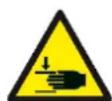
EN Warning against hand injuries (bruises)!
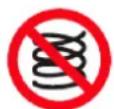
EN To compress springs or other elastic objects is forbidden!
4 VORWORT (DE)
natural_image
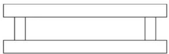
Simple line drawing of two stacked rectangular blocks with vertical supports (no text or symbols)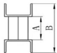
A: 164 ~mm
B: 184 mm
natural_image
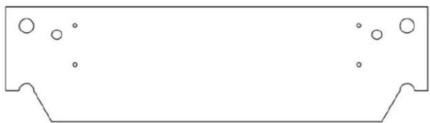
Pure technical diagram of a mechanical part with two flanges and circular holes, no text or symbols present.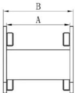
6 SICHERHEIT
8 BETRIEB
This manual contains information and important instructions for the installation and correct use of the shop presses WP 30H.
Following the usual commercial name of the device (see cover) is substituted in this manual with the name "machine".
This manual is part of the product and shall not be stored separately from the product. Save it for later reference and if you let other people use the product, add this instruction manual to the product.

Please read and obey the security instructions!
Before first use read this manual carefully. It eases the correct use of the product and prevents misunderstanding and damages of product and the user's health.
Due to constant advancements in product design, construction pictures and content may diverse slightly. However, if you discover any errors, inform us please.
Technical specifications are subject to changes!
Please check the product contents immediately after receipt for any eventual transport damage or missing parts.
Claims from transport damage or missing parts must be placed immediately after initial product receipt and unpacking before putting the product into operation.
Please understand that later claims cannot be accepted anymore.
Copyright
© 2017
This document is protected by international copyright law. Any unauthorized duplication, translation or use of pictures, illustrations or text of this manual will be pursued by law. Court of jurisdiction is the Landesgericht Linz or the competent court for 4170 Haslach, Austria!
Customer service contact
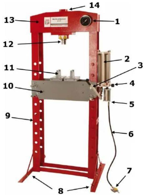
| 1 | Manometer |
| 2 | Hydraulic pump |
| 3 | Lever Hydraulic pump |
| 4 | Pressure valve |
| 5 | Air pressure pumpe |
| 6 | Air hose |
| 7 | FußFoot pedal with air port |
| 8 | Base support |
| 9 | Frame |
| 10 | Working table |
| 11 | Workpiece support |
| 12 | Stamp |
| 13 | Upper beam |
| 14 | Ram |
12.2 Technical details
| WP 30H | |
| Stroke | 150 mm |
| Working range | 151-1031 mm |
| Pressure performance | 30 t |
| Air port | 14 ” |
| Air Pressure | 0,75-0,85 MPa |
| Machine dimension | 795 x 700 x 1820 mm |
| Weight | 207 kg |
natural_image
Simple line drawing of two stacked rectangular blocks with vertical supports (no text or symbols)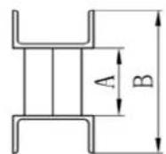
A: 164 ~mm
B: 184 mm
natural_image
Pure technical diagram of a rectangular component with two side supports and scattered circular features (no text or symbols)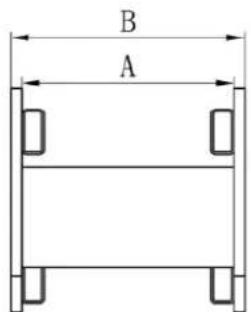
13 SAFETY
13.1 Intended Use
The machine must only be used for its intended purpose! Any other use is deemed to be a case of misuse.
To use the machine properly you must also observe and follow all safety regulations, the assembly instructions, operating and maintenance instructions lay down in this manual.
All people who use and service the machine have to be acquainted with this manual and must be informed about the machine's potential hazards.
It is also imperative to observe the accident prevention regulations in force in your area.
The same applies for the general rules of occupational health and safety.
The machine is used for:
Pressing-, bending- and straightening-work.
Any manipulation of the machine or its parts is a misuse, in this case HOLZMANN-MASCHINEN and its sales partners cannot be made liable for ANY direct or indirect damage.
Prohibited use:
- The operation of the machine outside the stated technical limits described in this manual is forbidden.
- The operation of the machine without provided protective devices is prohibited.
- The use of the machine not according with the required dimensions is forbidden.
- The use of the machine not being suitable for the use of the machine and not being certified is forbidden.
- The use of the machine for any purposes other than described in this user-manual is forbidden.
- Any manipulation of the machine and parts is forbidden.
- The unattended operation on the machine during the working process is forbidden.
- It is not allowed to leave the immediate work area during the work is being performed!
- It is forbidden to press any kind of spring or similar hard-to-stabilize workpieces.
• Not suitable for the industrial production of deep drawing parts!
13.2 Security instructions
Missing or non-readable security stickers have to be replaced immediately!
The locally applicable laws and regulations may specify the minimum age of the operator and limit the use of this machine!
To avoid malfunction, machine defects and injuries, read the following security instructions!

- Keep your work area dry and tidy! An untidy work area may cause accidents. Avoid slippery floor.
• Make sure the work area is lighted sufficiently! - Do not overload the machine!
• Always stay focused when working. Reduce distortion sources in your working environment. The operation of the machine when being tired, as well as under the influence of alcohol, drugs or concentration influencing medicaments is forbidden! - Do not climb onto the machine
- Attach the machine to the underground!
• Only one person shall operate the machine - The machine must be operated only by trained persons (knowledge and understanding of this manual), which have no limitations of motor skills compared with conventional workers
- Do not allow other people, particularly children, to touch the machine or the cable. Keep them away from your work area!
- Wear suitable work clothes! Do not wear loose clothing or jewelry as they might be caught and cause severe accidents.
- Wear a hair net if you have long hair
- Loose objects can become entangled and cause serious injuries!
- Use personal safety equipment: safety goggles, safety shoes S1, work wear, safety gloves (EN 388, class 3111) when working with or on the machine.
- Do not exceed in no case the max. pressing force of the shop press.
- Make sure that the workpiece surface, the stamp and the workpiece are free of lubricants and generally in a clean and dry condition.
- Use the Workshop Press exclusively on a solid, stable, level and non-slippery surface!
- Keep hands and feet away while operating from the working area of the pressure stamp.
- Ensure that the workpiece support as well as the workpiece are centrally positioned.
- Never leave the loaded press unattended and do not stand directly in front of the press during the pressing process.
- Store the press when not in use in a dry area with a retracted ram
13.3 Remaining risk factors

WARNING
It is important to ensure that each machine has remaining risks. In the execution of all work (even the simplest) greatest attention is required. A safe working depends on you!
Even if the machine is used as required it is still impossible to eliminate certain residual risk factors totally. The following hazards may arise in connection with the machine's construction and design:
- Risk of injury to the eye by flying debris, even with safety goggles.
- Risk of injury to the hands / fingers (bruises!)
These risk factors can be minimized through obeying all security and operation instructions, proper machine maintenance, proficient and appropriate operation by persons with technical knowledge and experience.
14 ASSEMBLY
14.1 Preparatory activities
Please check the product contents immediately after receipt for any eventual transport damage or missing parts. Claims from transport damage or missing parts must be placed immediately after initial machine receipt and unpacking before putting the machine into operation. Please understand that later claims cannot be accepted anymore.
14.1.1 Workplace requirements
The workplace has to fulfill the requirements.
The ground has to be even, in level and hard. It must be suitable at least to weight it with double weight per square meter than the machines net weight.
14.1.2 Preparation of the surface
Uncoated metal machine parts have been insulated with a greasy layer to inhibit corrosion.
This layer has to be removed. You can use standard solvents that do not damage the machine surface.

NOTICE
Do not use solvents based on nitrite, aggressive solvents like break cleaners or scrubbing agents!
These damage the machine surface
14.2 Assembly
Fix Base and base side supports with screws, washers and nuts.
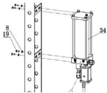
Mount the hydraulic pump.
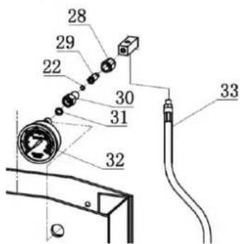
Mount the hydraulic hose using the O-ring to the ram. Attach the manometer.
Remark: twist as tight as possible, otherwise it will be leak.
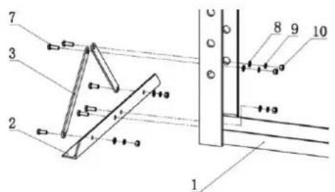
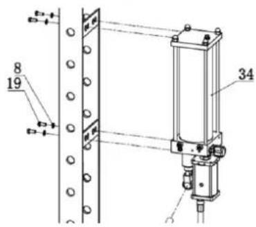
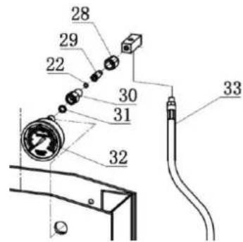
15 OPERATION
Machine to be operated in a perfect state only. Inspect the device visually every time it is to be used. Check in particular the safety equipment, electrical controls, electric cables and screwed connection for damage and if tightened properly. Replace any damaged parts before operating the device.
NOTICE
- Bleeding: Open the pressure valve fully. Pump the handle 10-15 times. Close the pressure valve and the stamp must go upwards.

15.1 Operation
- Place the workpiece support on the working table
- Insert the workpiece onto the workpiece support
- Close the pressure valve by turning it clockwise until it is firmly closed.
- Pump the handle or push foot pedal (pneumatic operation) until serrated saddle nears workpiece
- Check again:
- workpiece and ram to ensure center-loading.
- Pump the handle or push foot pedal to apply load onto workpiece.
• The pressure will be shown on the manometer! - ATTENTION: When work is done, stop pumping the handle, slowly and carefully remove load from workpiece by turning the release valve counterclockwise in small increments.
- Once ram has fully retracted, remove workpiece from bed frame.
15.1.1 Pneumatic operation
Connect the pneumatic foot control with compressed air hose at the air port. Press the foot control and the press cylinder now burdened the workpiece.
16 MAINTENANCE
The machine does not require extensive maintenance. If malfunctions and defects occur, let it be serviced by trained persons only.
Before first operation as well as later on every 100 operation hours you should lubricate all connecting parts (if required, remove beforehand with a brush all swarfs and dust).
Check regularly the condition of the security stickers. Replace them if required.
Check regularly the condition of the machine.
Store the machine in a closed, dry location.
NOTICE
Clean your machine regularly after every usage – it prolongs the machines lifespan and is a prerequisite for a safe working environment.
Repair jobs shall be performed by respectively trained professionals only!
16.1 Hydraulic oil
Check the hydraulic oil (HLP 46): Remove the oil filler nut on the pump, if it is not adequate, fill with high quality hydraulic oil (HLP 46) as necessary and then replace the oil filler nut, purge away air from the hydraulic system as described in a chapter before.
16.2 Cleaning
After each workshift the machine has to be cleaned.

NOT I CE
The usage of certain solutions containing ingredients damaging metal surfaces as well as the use of scrubbing agents will damage the machine surface!
Clean the machine surface with a wet cloth soaked in a mild solution
16.3 Disposal
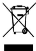
Do not dispose the machine, machine components fuel and oil in residual waste. Contact your local authorities for information regarding the available disposal options. When you buy at your local dealer for a replacement unit, the latter is obliged to exchange your old.
17 TROUBLE SHOOTING
| Trouble | Possible cause | Solution |
| Ram does not operate when is pimped | Pressure valve not tightly closed | Firmly close the pressure valve |
| Air in hydraulic system | Bleeding the pump:Open the pressure valve fully.Pump the handle 10-15 times.Close the pressure valve and the stamp must go upwards | |
| The steel ball is immersed inside for too long time | ||
| Ram will not hold load | Pressure valve not tightly closed | Firmly close the pressure valve |
| Malfunction in pump such as dirt inside the valve mechanism | Open the pressure valve fully.Pump the handle 10-15 times.Close the pressure valve and the stamp must go upwards | |
| Ram reluctant to lower when load removed | Oil reservoir overfilled | Drain oil to correct level |
| Piston binding | Clean and lubricate moving parts | |
| Overextended the ram | Replace ram | |
| Ram will not extend to full range of stroke | Low oil level | Add hydraulic oil HLP46 |
| Ram tries to tilt to one side | Incorrect connection or unbalance if the footing | Reposition Ram and base |

NO T ICE
Should you in necessary repairs not able to properly to perform or you have not the prescribed training for it always attract a workshop to fix the problem.
19 ERSATZTEILE / SPARE PARTS
With original HOLZMANN spare parts you use parts that are attuned to each other shorten the installation time and elongate your products lifespan.
I MP OR T AN T
The installation of other than original spare parts voids the warranty!
So you always have to use original spare parts
When you place a spare parts order please use the service formular you can find in the last chapter of this manual. Always take a note of the machine type, spare parts number and partname. We recommend to copy the spare parts diagram and mark the spare part you need.
You find the order address in the preface of this operation manual.
Overall drawing of machine Annex A
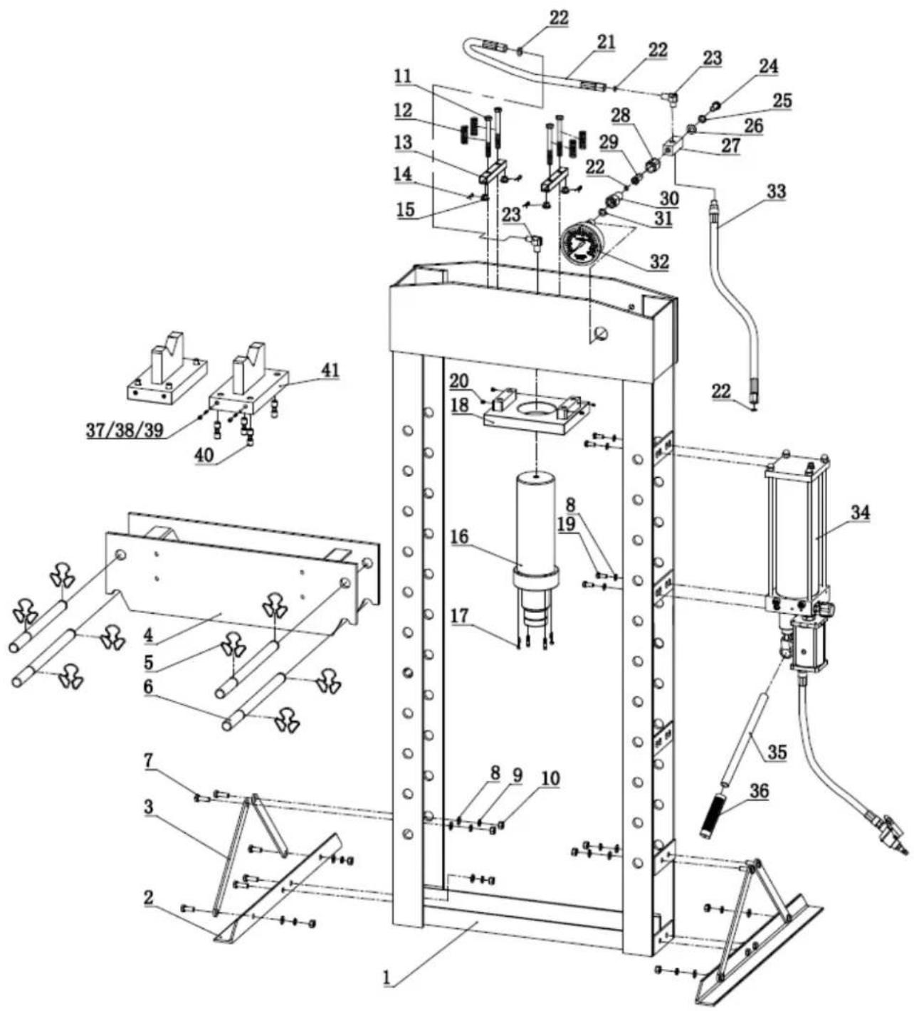
| NO. | Description | Qty | NO. | Description | Qty |
| 1 | Frame | 1 | 22 | O Ring | 4 |
| 2 | Base | 2 | 23 | Connector | 2 |
| 3 | Support Bar | 4 | 24 | Bolt | 1 |
| 4 | Working Table | 1 | 25 | Lock Washer | 1 |
| 5 | Cir-clip | 8 | 26 | Washer | 1 |
| 6 | Pin | 4 | 27 | Base for connector | 1 |
| 7 | Bolt | 12 | 28 | Nut | 1 |
| 8 | Washer | 16 | 29 | Screw | 1 |
| 9 | Lock Washer | 12 | 30 | Connector | 1 |
| 10 | Nut | 12 | 31 | Nylon Washer | 1 |
| 11 | Bolt | 4 | 32 | Pressure Gauge | 1 |
| 12 | Spring | 4 | 33 | Hose | 1 |
| 13 | Square Tube | 2 | 34 | Pump | 1 |
| 14 | R Pin | 4 | 35 | Handle Tube | 1 |
| 15 | Moving Piece | 4 | 36 | Handle Grip | 1 |
| 16 | Ram | 1 | 37 | Screw | 8 |
| 17 | Bolt | 4 | 38 | Spring | 8 |
| 18 | Ram Plate | 1 | 39 | Steel Ball | 8 |
| 19 | Bolt | 4 | 40 | Screw | 8 |
| 20 | Screw | 4 | 41 | Steel Block | 2 |
| 21 | Hose | 1 |
Main cylinders Annex B
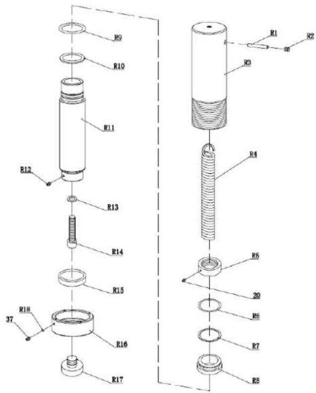
| NO. | Description | Qty |
| R1 | Pin | 1 |
| R2 | Screw | 1 |
| R3 | Ram | 1 |
| R4 | Spring | 1 |
| R5 | Nut | 1 |
| R6 | O Ring | 1 |
| R7 | Washer | 1 |
| R8 | Bushing | 1 |
| R9 | O Ring | 1 |
| R10 | Washer | 1 |
| R11 | Piston | 1 |
| R12 | Screw | 1 |
| R13 | Copper Washer | 1 |
| R14 | Screw | 1 |
| R15 | Upper Nut | 1 |
| R16 | Down Nut | 1 |
| R17 | Saddle | 1 |
| R18 | Nylon Rod | 1 |
| 20 | Screw | 1 |
| 37 | Screw | 1 |
Pump Annex C
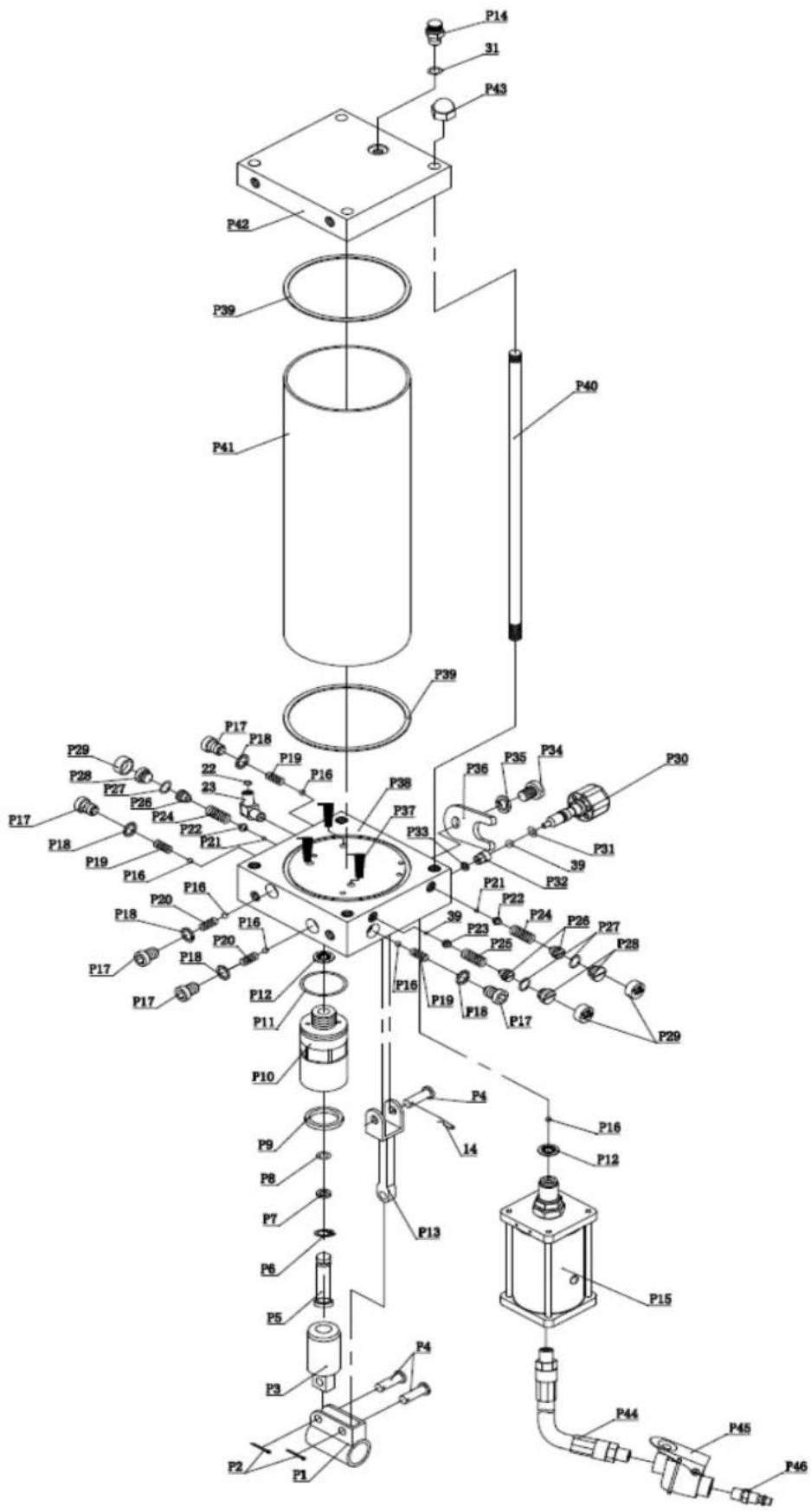
| NO. | Description | Qty | NO. | Description | Qty |
| P1 | Handle Bracket | 1 | P27 | O Ring | 3 |
| P2 | Pin | 2 | P28 | Screw | 3 |
| P3 | Big Piston | 1 | P29 | Cap | 3 |
| P4 | Pin | 3 | P30 | Release Valve | 1 |
| P5 | Small Piston | 1 | P31 | O Ring | 1 |
| P6 | Circlip | 1 | P32 | Base For Release Valve | 1 |
| P7 | Washer | 1 | P33 | Washer | 1 |
| P8 | O Ring | 1 | P34 | Screw | 1 |
| P9 | O Ring | 1 | P35 | Lock Washer | 1 |
| P10 | Piston Set | 1 | P36 | U Limit | 1 |
| P11 | O Ring | 1 | P37 | Filter | 3 |
| P12 | Copper Washer | 2 | P38 | Pump Base | 1 |
| P13 | Connector | 1 | P39 | Washer | 2 |
| P14 | Screw | 1 | P40 | Bar | 4 |
| P15 | Air Motor | 1 | P41 | Oil Tank | 1 |
| P16 | Ball | 6 | P42 | Cover | 1 |
| P17 | Screw | 5 | P43 | Nut | 4 |
| P18 | Washer | 5 | P44 | Air Hose | 1 |
| P19 | Spring | 3 | P45 | Air Valve | 1 |
| P20 | Spring | 2 | P46 | Air Hose Connector | 1 |
| P21 | Ball | 2 | 14 | R Pin | 1 |
| P22 | Ball Cup | 2 | 39 | Ball | 2 |
| P23 | Ball Cup | 1 | 31 | Nylon Ring | 1 |
| P24 | Spring | 2 | 23 | Connector | 1 |
| P25 | Spring | 1 | 22 | O Ring | 1 |
| P26 | Screw | 3 | 31 | Nylon Ring | 1 |
20 EU-KONFORMITÄTSERKLÄRUNG/CE-CERTIFICATE OF CONFORMITY

Inverkehrbringer / Distributor
Hereby we declare that the above mentioned machines meet the essential safety and health requirements of the above stated EC directives. Any manipulation or change of the machine not being explicitly authorized by us in advance renders this document null and void.
For mechanical and electrical components Company Holzmann Maschinen GmbH garants a warranty period of 2 years for DIY use and a warranty period of 1 year for professional/industrial use - starting with the purchase of the final consumer (invoice date).
In case of defects during this period which are not excluded by paragraph 3, Holzmann will repair or replace the machine at its own discretion.
2.) Report:
In order to check the legitimacy of warranty claims, the final consumer must contact his dealer. The dealer has to report in written form the occurred defect to Holzmann. If the warranty claim is legitimate, Holzmann will pick up the defective machine from the dealer. Returned shippings by dealers which have not been coordinated with Holzmann will not be accepted. A RMA number is an absolute must-have for us - we won't accept returned goods without an RMA number!
3.) Regulations:
a) Warranty claims will only be accepted when a copy of the original invoice or cash voucher from the trading partner of Holzmann is enclosed to the machine. The warranty claim expires if the accessories belonging to the machine are missing.
b) The warranty does not include free checking, maintenance, inspection or service works on the machine. Defects due to incorrect usage through the final consumer or his dealer will not be accepted as warranty claims either.
c) Excluded are defects on wearing parts such as carbon brushes, fangers, knives, rollers, cutting plates, cutting devices, guides, couplings, seals, impellers, blades, hydraulic oils, oil filters, sliding jaws, switches, belts, etc.
d) Also excluded are damages on the machine caused by incorrect or inappropriate usage, if it was used for a purpose which the machine is not supposed to, ignoring the user manual, force majeure, repairs or technical manipulations by not authorized workshops or by the customer himself, usage of non-original Holzmann spare parts or accessories.
e) After inspection by our qualified staff, resulted costs (like freight charges) and expenses for not legitimated warranty claims will be charged to the final customer or dealer.
f) In case of defective machines outside the warranty period, we will only repair after advance payment or dealer's invoice according to the cost estimate (incl. freight costs) of Holzmann.
g) Warranty claims can only be granted for customers of an authorized Holzmann dealer who directly purchased the machine from Holzmann. These claims are not transferable in case of multiple sales of the machine.
4.) Claims for compensation and other liabilities:
The liability of company Holzmann is limited to the value of goods in all cases.
Claims for compensation because of poor performance, lacks, damages or
loss of earnings due to defects during the warranty period will not be accepted.
Holzmann insists on its right to subsequent improvement of the machine.
SERVICE
After Guarantee and warranty expiration specialist repair shops can perform maintenance and repair jobs. But we are still at your service as well with spare parts and/or product service. Place your spare part / repair service cost inquiry by filing the SERVICE form on the following page and send it:
via Mail to info@holzmann-maschinen.at
or via Fax to: +43 7289 71562 4
24 PRODUKTBEOBACHTUNG PRODUCT EXPERIENCE FORM
We observe the quality of our delivered products in the frame of a Quality Management policy.
Your opinion is essential for further product development and product choice. Please let us know about your:
- Impressions and suggestions for improvement.
- experiences that may be useful for other users and for product design
- Experiences with malfunctions that occur in specific operation modes
We would like to ask you to note down you experiences and observations and send them to us via FAX, E-Mail or by post:
Erworben von / purchased from:
E-Mail/ e-mail:
service inquiry spare part inquiry guarantee claim
Please describe amongst others in the problem: What has cause the problem/defect, what was the last activity before you noticed the problem/defect? For electrical problems: Have you had checked you electric supply and the machine already by a certified electrician?
3. Bitte beachten
Additional information
INCOMPLETELY FILLED SERVICE FORMS CANNOT BE PROCESSED! FOR GUARANTEE CLAIMS PLEASE ADD A COPY OF YOUR ORIGINAL SALES / DELIVERY RECEIPT OTHERWISE IT CANNOT BE ACCEPTED. FOR SPARE PART ORDERS PLEASE ADD TO THIS SERVICE FORM A COPY OF THE RESPECTIVE EXPLODED DRAWING WITH THE REQUIRED SPARE PARTS BEING MARKED CLEARLY AND UNMISTAKABLE. THIS HELPS US TO IDENTIFY THE REQUIRED SPARE PARTS FASTLY AND ACCEL- ERATES THE HANDLING OF YOUR INQUIRY.
- INHALT /INDEX
- ASSEMBLY 17
- OPERATION 18
- MAINTENANCE 19
- TROUBLE SHOOTING 20
- VORWORT (DE)
- SICHERHEIT
- BETRIEB
- Please read and obey the security instructions!
- Copyright
- Customer service contact
- Technical details
- SAFETY
- Intended Use
- Prohibited use:
- Security instructions
- Remaining risk factors
- WARNING
- ASSEMBLY
- Preparatory activities
- Workplace requirements
- Preparation of the surface
- NOTICE
- Assembly
- OPERATION
- Operation
- Pneumatic operation
- MAINTENANCE
- Hydraulic oil
- Cleaning
- NOT I CE
- Disposal
- TROUBLE SHOOTING
- NO T ICE
- ERSATZTEILE / SPARE PARTS
- I MP OR T AN T
- The installation of other than original spare parts voids the warranty!
- EU-KONFORMITÄTSERKLÄRUNG/CE-CERTIFICATE OF CONFORMITY
- Inverkehrbringer / Distributor
- 2.) Report:
- 3.) Regulations:
- 4.) Claims for compensation and other liabilities:
- SERVICE
- PRODUKTBEOBACHTUNG PRODUCT EXPERIENCE FORM
- Bitte beachten
- Additional information
Brand : Holzmann
Model : WP 30H
Category : Uncategorized