
301E - Measurement FLUKE - Free user manual and instructions
Find the device manual for free 301E FLUKE in PDF.


| Product Type | Clamp Meter |
| Model | 301E |
| Brand | Fluke |
| Dimensions (L x W x H) | 199 mm x 52 mm x 16 mm |
| Weight (with batteries) | 154 g |
| Power Supply | 2 AAA IEC LR03 alkaline batteries |
| Display | 6000 counts LCD, updates 3/sec |
| Auto Power Off | 20 minutes |
| Jaw Opening | 34 mm |
| Ingress Protection | IP30 (non-operating) |
| Safety Rating | CAT III 300 V, IEC 61010-1 |
| Maximum Voltage between any Terminal and Earth Ground | 300 V |
| Maximum Voltage between V/Ω Terminal and COM Terminal | 600 V |
| Operating Temperature | -10 °C to 50 °C |
| Storage Temperature | -30 °C to 60 °C |
| Operating Humidity | ≤90% RH at 10°C to 30°C, ≤75% RH at 30°C to 40°C, ≤45% RH at 40°C to 50°C |
| Altitude (Operating) | 2000 m |
| Altitude (Storage) | 12000 m |
| Temperature Coefficient | 0.1 x (specified accuracy)/°C (<18°C or >28°C) |
| Functions | AC/DC voltage, AC/DC current, resistance, continuity, diode, capacitance, frequency |
| AC Current Range (301E) | 60.00 A / 600.0 A / 1000 A |
| DC Current Range (301E) | 60.00 A / 600.0 A / 1000 A |
| AC Voltage Range | 600.0 V |
| DC Voltage Range | 600.0 V |
| Resistance Range | 600.0 Ω / 6.000 kΩ / 60.0 kΩ |
| Capacitance Range | 9.999 μF / 99.99 μF / 999.9 μF |
| Frequency Range (Voltage) | 1 Hz to 99.99 kHz |
| Continuity Threshold | 30 Ω |
| Diode Test Voltage | 3.000 V |
| User-Replaceable Parts | Battery, battery door, test leads |
| Warranty | 1 year |
Frequently Asked Questions - 301E FLUKE
User questions about 301E FLUKE
0 question about this device. Answer the ones you know or ask your own.
Ask a new question about this device
Download the instructions for your Measurement in PDF format for free! Find your manual 301E - FLUKE and take your electronic device back in hand. On this page are published all the documents necessary for the use of your device. 301E by FLUKE.
USER MANUAL 301E FLUKE
301A/301B/301C/301D/301E
Clamp Meter
Calibration Manual
LIMITED WARRANTY AND LIMITATION OF LIABILITY
Each Fluke product is warranted to be free from defects in material and workmanship under normal use and service. The warranty period is 1 year and begins on the date of shipment. Parts, product repairs, and services are warranted for 90 days. This warranty extends only to the original buyer or end-user customer of a Fluke authorized reseller, and does not apply to fuses, disposable batteries, or to any product which, in Fluke's opinion, has been misused, altered, neglected, contaminated, or damaged by accident or abnormal conditions of operation or handling. Fluke warrants that software will operate substantially in accordance with its functional specifications for 90 days and that it has been properly recorded on non-defective media. Fluke does not warrant that software will be error free or operate without interruption.
Fluke authorized resellers shall extend this warranty on new and unused products to end-user customers only but have no authority to extend a greater or different warranty on behalf of Fluke. Warranty support is available only if product is purchased through a Fluke authorized sales outlet or Buyer has paid the applicable international price. Fluke reserves the right to invoice Buyer for importation costs of repair/ replacement parts when product purchased in one country is submitted for repair in another country.
Fluke's warranty obligation is limited, at Fluke's option, to refund of the purchase price, free of charge repair, or replacement of a defective product which is returned to a Fluke authorized service center within the warranty period.
To obtain warranty service, contact your nearest Fluke authorized service center to obtain return authorization information, then send the product to that service center, with a description of the difficulty, postage and insurance prepaid (FOB Destination). Fluke assumes no risk for damage in transit. Following warranty repair, the product will be returned to Buyer, transportation prepaid (FOB Destination). If Fluke determines that failure was caused by neglect, misuse, contamination, alteration, accident, or abnormal condition of operation or handling, including overvoltage failures caused by use outside the product's specified rating, or normal wear and tear of mechanical components, Fluke will provide an estimate of repair costs and obtain authorization before commencing the work. Following repair, the product will be returned to the Buyer transportation prepaid and the Buyer will be billed for the repair and return transportation charges (FOB Shipping Point).
THIS WARRANTY IS BUYER'S SOLE AND EXCLUSIVE REMEDY AND IS IN LIEU OF ALL OTHER WARRANTIES, EXPRESS OR IMPLIED, INCLUDING BUT NOT LIMITED TO ANY IMPLIED WARRANTY OF MERCHANTABILITY OR FITNESS FOR A PARTICULAR PURPOSE. FLUKE SHALL NOT BE LIABLE FOR ANY SPECIAL, INDIRECT, INCIDENTAL OR CONSEQUENTIAL DAMAGES OR LOSSES, INCLUDING LOSS OF DATA, ARISING FROM ANY CAUSE OR THEORY.
Since some countries or states do not allow limitation of the term of an implied warranty, or exclusion or limitation of incidental or consequential damages, the limitations and exclusions of this warranty may not apply to every buyer. If any provision of this Warranty is held invalid or unenforceable by a court or other decision-maker of competent jurisdiction, such holding will not affect the validity or enforceability of any other provision.
Fluke Corporation
P.O. Box 9090
Everett, WA 98206-9090
U.S.A.
Table of Contents
Title Page
Introduction.... 1
Contact Fluke 1
Safety Information.... 1
Static Awareness 2
Specifications 3
Accuracy 3
General.... 4
Safety.... 5
Maintenance 5
Battery Replacement 5
Jaw Maintenance 6
User-Replaceable Parts.... 6
Product Disposal.... 6
Required Equipment 7
Performance Tests.... 7
Display and Firmware Version....7
Backlight 8
Button Test 8
Current 8
Volts and Ohms.... 10
Calibration Adjustment.... 12
Introduction
The Fluke 301A/301B/301C/301D/301E Clamp Meter (the Product or Clamp) measures ac and dc voltage, ac and dc current, resistance, continuity, diode, capacitance, and frequency. All illustrations show the 301B unless otherwise specified.
Contact Fluke
Fluke Corporation operates worldwide. For local contact information, go to our website: www.fluke.com
To register your product, or to view, print, or download the latest manual or manual supplement, go to our website: www.fluke.com/productinfo
Fluke Corporation
Fluke Europe B.V.
P.O. Box 9090
P.O. Box 1186
Everett WA 98206-9090
5602 BD Eindhoven
U.S.A.
The Netherlands
+1-425-446-5500 fluke-info@fluke.com
Safety Information
Warning
Read Safety Information before you use the Product.
General Safety Information is in the printed Safety Information document that ships with the Product and at www.fluke.com. More specific safety information is listed where applicable.
A Warning identifies hazardous conditions and procedures that are dangerous to the user. A Caution identifies conditions and procedures that can cause damage to the Product or the equipment under test.
Static Awareness
Semiconductors and integrated circuits can be damaged by electrostatic discharge during handling. This notice explains how to minimize damage to these components.
- Understand the problem.
- Learn the guidelines for proper handling.
- Use the proper procedures, packaging, and bench techniques.
Follow these practices to minimize damage to static sensitive parts.
Warning
To prevent electric shock or personal injury. De-energize the product and all active circuits before opening a product enclosure, touching or handling any PCBs or components.

natural_image
Illustration of a hand holding an integrated circuit chip (no text or symbols)- Minimize handling.
- Handle static-sensitive parts by non-conductive edges.
- Do not slide static-sensitive components over any surface.
- When removing plug-in assemblies, handle only by non-conductive edges.
- Never touch open-edge connectors except at a static-free work station.
natural_image
Illustration of an integrated circuit chip and its external I-beam (no text or symbols)- Keep parts in the original containers until ready for use.
- Use static shielding containers for handling and transport.
- Avoid plastic, vinyl, and polystyrene foam in the work area.

natural_image
Pure electrical circuit symbol for a lamp (no text or labels)- Handle static-sensitive parts only at a static-free work station.
- Put shorting strips on the edge of the connector to help protect installed static-sensitive parts.
- Use anti-static type solder extraction tools only.
- Use grounded-tip soldering irons only.
Specifications
Accuracy
Accuracy is specified for 1 year after calibration at operating temperatures of 18 °C to 28 °C , relative humidity a 0 % to 75 %. Accuracy specifications take the form of:
±([% of Reading] + [Number of Least Significant Digits]).
| Function Range | Resolution | Accuracy | |||||
| 301A 301B 301C | 301D 301E | ||||||
| AC Volts(45 Hz to 400 Hz) | 600.0 V 0.1 | V 1.5 %+5 | |||||
| Voltage Frequency(HZ)1 Hz to 99.99 kHzThreshold 10.0 V | 9.999 Hz 0.001 Hz | 0.1 %+3 | |||||
| 99.99 Hz 0.01 Hz | |||||||
| 999.9 Hz 0.1 Hz | |||||||
| 9.999 kHz 0.001 kHz | |||||||
| 99.99 kHz 0.01 kHz | |||||||
| DC Volts | 600.0 V 0.1 | V 1 %+5 | |||||
| Ω ResistanceContinuityThreshold: 30 Ω | 600.0 Ω 0.1 | Ω | 1 %+5 | ||||
| 6.000 kΩ | 0.001 kΩ | ||||||
| 60.0 kΩ 0.01 kΩ | |||||||
| Capacitance | 9.999 μF | 0.001 μF | 2 %+5 | ||||
| 99.99 μF | 0.01 μF | 5 %+5 | |||||
| 999.9 μF | 0.1 μF | 5 %+5 | |||||
| Diode | 3.000 V 0.001 V 10 % | ||||||
| AC Current A(45 Hz to 400 Hz) | 40.00 A[2] | 0.01 A | 2 %+10 | NA | NA | NA | NA |
| 400.0 A | 0.1 A | 2 %+5 | NA | NA | NA | NA | |
| 60.00 A[2] | 0.01 A | NA | 2 %+10 | 2 %+10 | 2 %+10 | 2 %+10 | |
| 600.0 A | 0.1 A | NA | 2 %+5 | 2 %+5 | 2 %+5 | 2 %+5 | |
| 1000 A | 1 A | NA | NA | 2 %+5 | NA | 2 %+5 | |
| AAC Frequency (Hz)Threshold 10.00A | 45.0 Hz to400.0 Hz | 0.1 Hz | 0.1 %+3 | ||||
| DC Current [1] | 60.00 A[2] | 0.01A | NA | NA | NA | 2 %+10 | |
| 600.00 A | 0.1 A | NA | NA | NA | 2 %+5 | ||
| 1000 A | 1 A | NA | NA | NA | NA | 2 %+5 | |
| [1] After zero operation.[2] <1 % range, unspecified. | |||||||
General
Maximum Voltage
Between any Terminal and
Earth Ground.... 300 V
Between V/Ω Terminal and
COM Terminal 600 V
Display (LCD).... 6000 counts, updates 3/sec
Battery Type.... 2 AAA IEC LR03 alkaline
Automatic Power Off 20 minutes
Temperature
Operating ...... -10 °C to 50 °C
Storage ...... -30 °C to 60 °C
Operating Humidity...... Non condensing (<10°C)
≤90 % RH (at 10 °C to 30 °C)
≤75 % RH (at 30 °C to 40 °C)
≤45 % RH (at 40 °C to 50 °C)
Altitude
Operating 2000 m
Storage 12 000 m
Temperature Coefficient.... 0.1 x (specified accuracy) /°C (<18 °C or >28 °C)
Size (L x W x H) 199 mm x 52 mm x 16 mm
Weight (with batteries)
301A/B/C.... 132 g
301D/E 154 g
Jaw Opening 34 mm
Ingress Protection (IP) Rating...... IEC 60529: IP30 non-operating
Electromagnetic Environment...... IEC 61326-1: Portable
Electromagnetic Compatibility (EMC)
International IEC 61326-1: Portable, Electromagnetic Environment,
IEC 61326-2-2
CISPR 11: Group 1, Class A
Group 1: Equipment has intentionally generated and/or uses conductively-coupled radio frequency energy that is necessary for the internal function of the equipment itself.
Class A: Equipment is suitable for use in all establishments other than domestic and those directly connected to a low-voltage power supply network that supplies buildings used for domestic purposes. There may be potential difficulties in ensuring electromagnetic compatibility in other environments due to conducted and radiated disturbances.
Caution: This equipment is not intended for use in residential environments and may not provide adequate protection to radio reception in such environments.
Korea (KCC) ...... Class A Equipment (Industrial Broadcasting & Communication Equipment)
Class A: Equipment meets requirements for industrial electromagnetic wave equipment and the seller or user should take notice of it. This equipment is intended for use in business environments and not to be used in homes.
USA (FCC)....47 CFR 15 subpart B. This product is considered an exempt device per clause 15.103.
Safety
General IEC 61010-1, Pollution Degree 2
Measurement....IEC 61010-1, Pollution Degree 2
IEC 61010-2-032: CAT III 300 V
Maintenance
Caution
To prevent possible damage to the Product or to equipment under test, do not use abrasive cleansers.
Periodically wipe the case with a damp cloth and mild detergent. Do not use abrasives or solvents. Dirt or moisture in the terminals can affect readings.
Battery Replacement
Warning
To prevent possible explosion, fire, or personal injury, replace the batteries when the low battery indicator (+) shows to prevent incorrect measurements.
Caution
To prevent possible damage to the Product or to equipment under test:
- Remove batteries to prevent battery leakage and damage to the Product if it is not used for an extended period.
- Be sure that the battery polarity is correct to prevent battery leakage.
Figure 1 shows how to replace the battery.
Figure 1. Battery Replacement
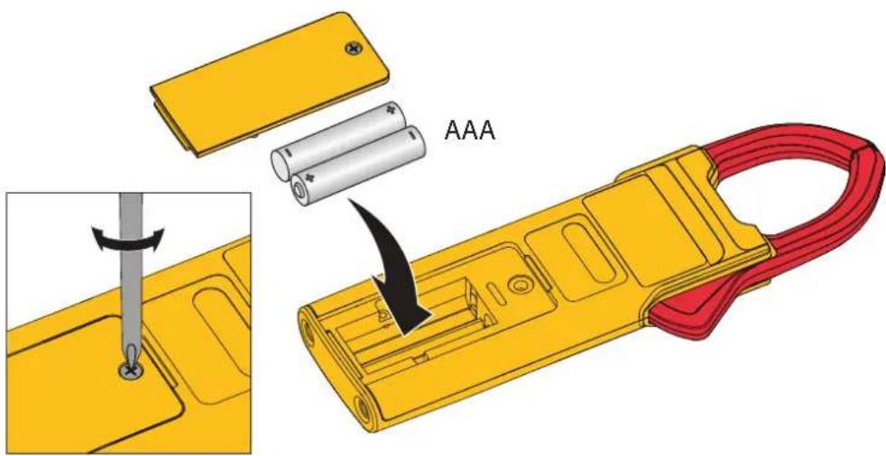
To replace the batteries:
- Turn off the Product.
- Turn over the Product to access the battery compartment door screw.
- Use a flat-head screwdriver to loosen the battery compartment door screw and lift off the battery compartment door.
- Replace the two AAA batteries. Make sure to use the correct polarity when you put the batteries into the battery compartment door.
- Reattach the battery compartment door.
- Tighten the battery compartment door screw.
Jaw Maintenance
If the Product does not work properly:
- Inspect the jaw mating surface for cleanliness. If any foreign material (including rust) is present, the jaw will not close properly and measurement errors will result.
- Open the jaws and wipe the clamp metal ends with a non-flammable oil and cloth.
User-Replaceable Parts
Table 1 is a list of the user-replaceable parts. To order parts, see Contact Fluke.
Table 1. User-Replaceable Parts
| Item Quantity Fluke Part Number | |
| Battery AAA 1.5 V 1 5128983 | |
| Battery Door 1 5336951 | |
| TL75, Test Lead with 2 Caps 1 4306653 |
Product Disposal
Dispose of the Product in a professional and environmentally sound manner:
- Delete personal data on the Product before disposal.
- Remove batteries that are not integrated into the electrical system before disposal and dispose of batteries separately.
- If this Product has an integral battery, put the entire Product in the electrical waste.
Required Equipment
Table 2 is a list of the equipment that is necessary for the performance tests and calibration adjustment.
Table 2. Equipment Requirements
| Equipment Required Characteristics Recommended Model | ||
| Calibrator 4.5-digit resolution | on 5522A or equivalent | |
| Wired Coil | 50 turns | 5500A/Coil or equivalent |
Performance Tests
Warning
To prevent possible electrical shock, fire, or personal injury, do not go through the performance test procedures unless the Product is fully assembled.
The performance tests verify the full operation of the Product and measure the accuracy of each function against the Product specifications. If the Product fails a part of the test, calibration adjustment and/or repair is necessary. See Calibration Adjustment.
Before you do the performance tests:
- Make sure that you have the necessary equipment. See Table 2.
- Make sure the Product batteries are charged or replace them if necessary. See Battery Replacement.
- Warm up the Calibrator as necessary. Refer to its specifications.
- Let the temperature of the DUT (device under test) become stable to room temperature.
Display and Firmware Version
To verify that all segments of the display function:
- With the Product off, push and hold HOLD.
- Turn the Product on.
- All display segments are shown. See Figure 2.
If segments of the display are missing, repair is necessary. See Contact Fluke.
Figure 2. Display Segments
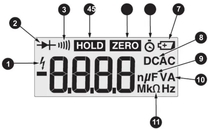
When HOLD is released, the firmware current version shows, for example, r013. F301 designates the model number.
Backlight
To verify that the backlight functions:
- With the Product on, long press ☐. The backlight comes on.
- Long press □ again to turn off the backlight.
- If the backlight does not function correctly, repair is necessary. See Contact Fluke.
Button Test
To verify that the buttons function, turn on the Product and push each button separately. Each button push causes the Product to beep. When you push HOLD, HOLD shows on the display. If the buttons do nothing, repair is necessary. See Contact Fluke
Current
To do the current test:
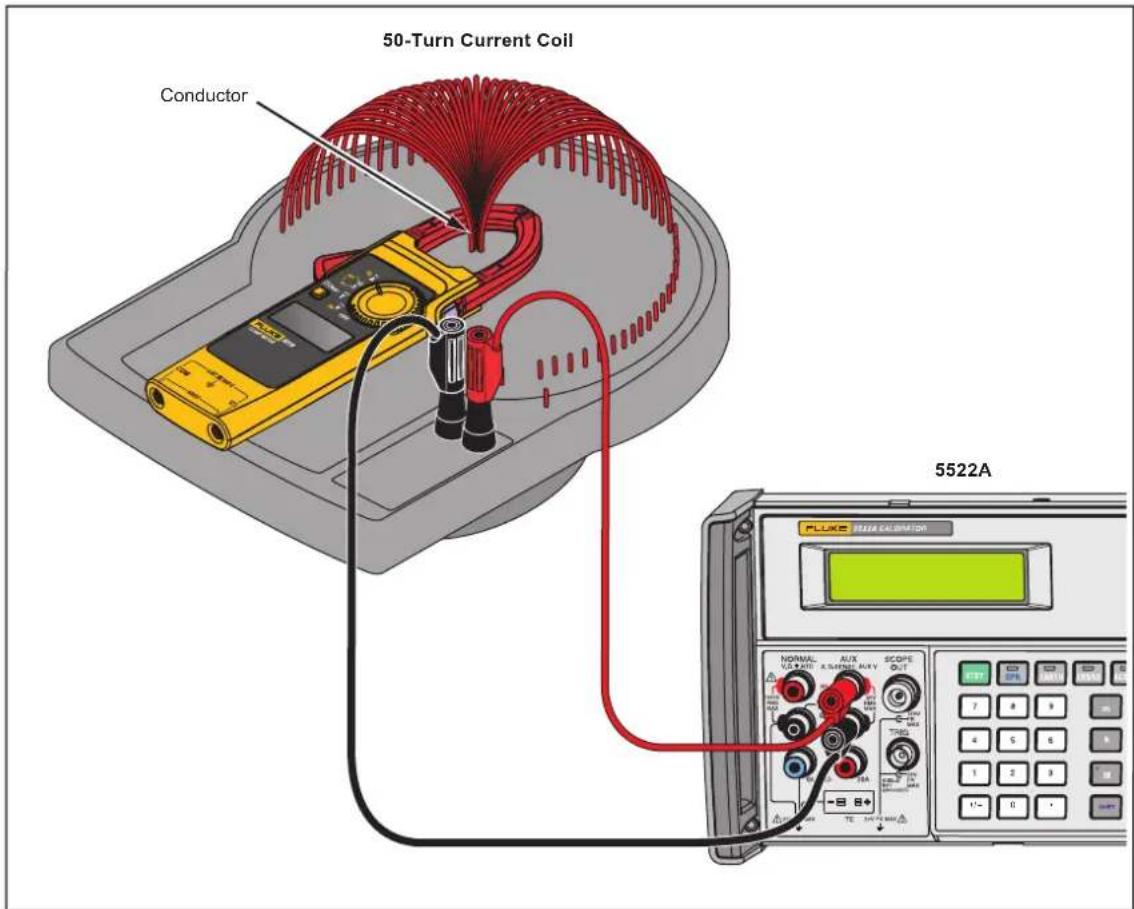
- Connect the Calibrator Amp output and ground to the 50-Turn Coil. See Figure 3 for test connections.
- Turn the rotary switch to .
- Apply the input level for each step shown in Table 3.
- Compare the indication on the Product display with the DUT reading limits in Table 3. If the display indication is outside of the range shown in Table 3, calibration adjustment or repair of the Product is necessary. See Calibration Adjustment.
Table 3. Current Performance Tests
| Value Unit | Frequency or Amplitude | Res. | Spec. Counts | 301 Model | Lower Limit | Upper Limit | ||||||
| A | B | C | D | E | ||||||||
| A ac (with 50-turn coil) | ||||||||||||
| 0.2 | 1 10 A | 5 0 | 0.01 | 2 %z | 10 | ● | ● | ● | ● | ● | 9.7 10.3 | |
| 0.8 0.0 | ● | ● | ● | ● | ● | 39.10 4 | 0.90 | |||||
| 2 | 0 | ● | ● | ● | ● | ● | 97.5 1 | 102.5 | ||||
| 8 | 0 H | ● | 391.5 4 | 08.5 | ||||||||
| 12 | 0.1 | 5 | ● | ● | ● | ● | 587.5 6 | 12.5 | ||||
| 14 | 1 | 5 | ● | ● | 681 | 719 | ||||||
| 19.5 | 1 | 5 | ● | ● | 951 | 1000 | ||||||
| A ac, Hz (with 50-turn coil) | ||||||||||||
| 45.0 | Hz | 0.2 A | 0.1 | 0.1 % | 3 | ● | ● | ● | ● | ● | 44.7 | 45.3 |
| 400.0 | 3 | ● | ● | ● | ● | ● | 399.3 4 | 00.7 | ||||
| 45.0 | 8 A | 3 | ● | ● | ● | ● | ● | 44.7 | 45.3 | |||
| 400.0 | 3 | ● | ● | ● | ● | ● | 399.3 4 | 00.7 | ||||
| A dc (with 50-turn coil) must zero for each point | ||||||||||||
| -16 | 1 10 1A0 | 0 H | 1 | 2 % | 5 | ● | -821 | -779 | ||||
| -6 | 0.1 | 5 | ● | ● | -306.5 | -293.5 | ||||||
| -0.6 | 0.01 10 | ● | ● | -30.70 | -29.30 | |||||||
| 0.2 0.0 | ● | ● | 9.70 | 10.30 | ||||||||
| 1.2 0.0 | z | ● | ● | 58.7 | 61.3 | |||||||
| 2 | 0.1 | 5 | ● | ● | 97.5 | 102.5 | ||||||
| 12 | 0.1 | 5 | ● | ● | 587.5 6 | 12.5 | ||||||
| 14 | 1 | 5 | ● | 681 | 719 | |||||||
| 19.5 | 1 | 5 | ● | 951 | 1000 | |||||||
Figure 3. AC Current Test Connections
Volts and Ohms
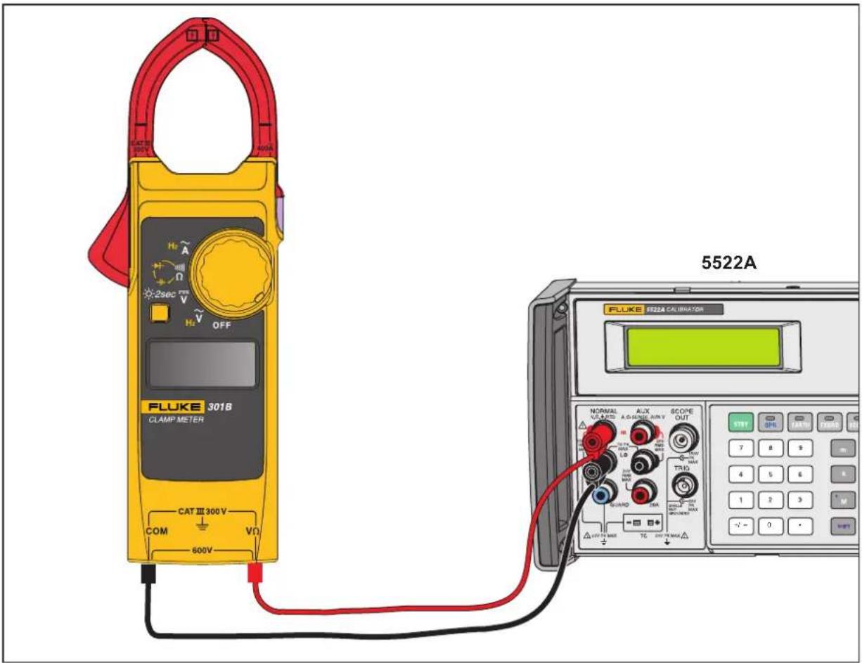
To do the Volts and Ohms performance tests, turn the rotary switch to the necessary function and apply the values shown in Table 4. See Figure 4 for the test connections.
Table 4. Volts and Ohms Performance Tests
| Value Unit | Frequency or Amplitude | Res. | Spec. | Counts | 301 Model | Lower Limit | Upper Limit | ||||||
| A | B | C | D | E | |||||||||
| V ac | |||||||||||||
| 20 | V | 20 Hz | 0.1 | 1.5 | 0 % 5 | ● | ● | ● | ● | ● | 19.2 20.8 | ||
| 10 | 50 Hz | ● | ● | ● | ● | ● | 9.4 10.7 | ||||||
| 500 | ● | ● | ● | ● | ● | 492.0 508.0 | |||||||
| 10 | 400 Hz | ● | ● | ● | ● | ● | 9.4 10.7 | ||||||
| 500 | ● | ● | ● | ● | ● | 492.0 508.0 | |||||||
| Hz (V ac) | |||||||||||||
| 9 | Hz | 10 V | 0.001 | 0.10 % 3 | ● | ● | ● | ● | ● | 8.988 9012 | |||
| 15 Hz | 0.01 | ● | ● | ● | ● | ● | 14.96 15.05 | ||||||
| 900 | Hz 0.1 | ● | ● | ● | ● | ● | 898.8 901.2 | ||||||
| 1.5 | kHz 0.001 | ● | ● | ● | ● | ● | 1.496 1.505 | ||||||
| 90.0 kHz | Hz 0.01 | ● | ● | ● | ● | ● | 89.88 90.12 | ||||||
| V dc | |||||||||||||
| -10 | V 0 Hz | 0.1 | 1.00 % 5 | ● | ● | ● | ● | ● | -10.6 | -9.4 | |||
| 10 | ● | ● | ● | ● | ● | 9.4 10.6 | |||||||
| 500 | ● | ● | ● | ● | ● | 494.5 505.5 | |||||||
| Ohm | |||||||||||||
| 0 | Ω | 0.1NA | 0.1 | 1.00 % 5 | ● | ● | ● | ● | ● | -0.5 | 0.5 | ||
| 10 Ω | ● | ● | ● | ● | ● | 9.4 10.6 | |||||||
| 300 | Ω | 0.1 | ● | ● | ● | ● | ● | 296.5 303.5 | |||||
| 3 | kΩ | 0.001 | ● | ● | ● | ● | ● | 2.965 3035 | |||||
| 30 kΩ | 0.01 | ● | ● | ● | ● | ● | 29.65 30.35 | ||||||
| Capacitance | |||||||||||||
| 0.05 | μF | NA | 0.001 | 2.00 % | 5 | ● | ● | ● | ● | ● | 0.044 0056 | ||
| 0.5 | 0.001 | 2.00 % | ● | ● | ● | ● | ● | 0.485 0515 | |||||
| 5 | 0.001 | 2.00 % | ● | ● | ● | ● | ● | 4.895 5105 | |||||
| 90 | 0.01 5.00 % | ● | ● | ● | ● | ● | 85.45 94.55 | ||||||
| 500 | 0.1 5.00 % | ● | ● | ● | ● | ● | 474.5 525.5 | ||||||
| Diode | |||||||||||||
| 0.7 V NA | 0.001 | 10.00 % | 7 | ● | ● | ● | ● | ● | 0.630 0770 | ||||
Figure 4. Volts and Ohms Performance Test Connections
Calibration Adjustment
The Product features closed-case calibration adjustment and uses known reference sources. The Product measures the applied reference source, calculates correction factors, and stores the correction factors in nonvolatile memory.
Should the Product fail any of the performance tests, do the calibration adjustment procedure.
For information about damage by electrostatic discharge, see Static Awareness.
To do the calibration adjustment:
- Remove the Product battery door. See Battery Replacement.
- Apply 3.0 V across the battery contacts on the PCA. Note the polarity in Figure 5.
- Turn the rotary switch to the function to OFF.
-
Remove the calibration seal.
-
While shorting across the CAL keypad on the PCA, turn the rotary switch to the function to adjust. See Figure 5.
-
When CAL shows on the display, remove the short.
This puts the Product into calibration mode.
-
When the real value shows on the display, apply the correct input signals from Table 5 to the Product. For each function, the calibration step shown on the display will advance.
-
After each step, push on the front to confirm the calibration step, store the value, and go to the next step.
-
Set the Calibrator to Standby after you complete adjustment of each function.
Note
If any calibration point is missing, Err is shown on the display.
After you push ☐, wait until the calibration step number advances before you change the calibrator source. Some adjustment steps can take several seconds to execute before the Product goes to the next step.
- When calibration adjustment is complete, remove the 3.0 V supply.
The Product exits the calibration mode automatically.
- Replace the batteries and battery door.
Figure 5. CAL Keyboard
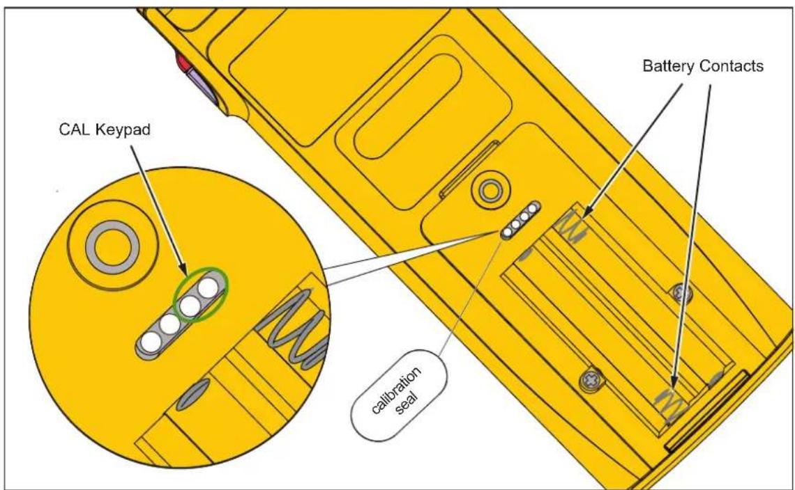
Table 5. Calibration Adjustment
| RSOB Position | Value Unit | Frequency or Amplitude | Calibration Step | 301 Model | |||||
| A | B | C | D | E | |||||
| Wait for Self-Calibration until display shows MV | |||||||||
 | 500.0 mV | 0 Hz | C-1.1 | ● | ● | ● | ● | ● | |
| 300.0 Ω C-2.1 | ● | ● | ● | ● | ● | ||||
| 50.00 kΩ C-2.2 | ● | ● | ● | ● | ● | ||||
| 100 nF C-3.1 | ● | ● | ● | ● | ● | ||||
| 50.00 | μF | C-3.2 | ● | ● | ● | ● | ● | ||
| 30.00 A | 60 Hz | C-4.1 | ● | ● | ● | ● | ● | ||
| 300.0 A C-4.2 | ● | ● | ● | ● | ● | ||||
| 800 A C-4.3 | ● | ● | |||||||
| 0.00 A | 0 Hz | C-5.1 | ● | ● | |||||
| 30.00 A C-5.2 | ● | ● | |||||||
| 0.0 A C-5.3 | ● | ● | |||||||
| 300.0 A C-5.4 | ● | ● | |||||||
| 0 | A | C-5.5 | ● | ||||||
| 800 A C-5.6 | ● | ||||||||
| [IMAGE] | 300.0 V | 0 Hz | C-7.1 | ● | ● | ● | ● | ● | |
| 300.0 | V | 60 Hz | C-7.2 | ● | ● | ● | ● | ● | |
- 301A/301B/301C/301D/301E
- Clamp Meter
- LIMITED WARRANTY AND LIMITATION OF LIABILITY
- Table of Contents
- Title Page
- Introduction
- Contact Fluke
- Safety Information
- Static Awareness
- Specifications
- Accuracy
- General
- Maximum Voltage
- Temperature
- Altitude
- Weight (with batteries)
- Electromagnetic Compatibility (EMC)
- Safety
- Maintenance
- Caution
- Battery Replacement
- Warning
- Jaw Maintenance
- User-Replaceable Parts
- Product Disposal
- Required Equipment
- Performance Tests
- Display and Firmware Version
- Backlight
- Button Test
- Current
- Volts and Ohms
- Calibration Adjustment
- Note
Brand : FLUKE
Model : 301E
Category : Measurement