
RHB-200 - Remote control ROTEL - Free user manual and instructions
Find the device manual for free RHB-200 ROTEL in PDF.


| Product Type | Remote Control |
| Brand | Rotel |
| Model | RHB-200 |
| Compatible Devices | Rotel audio components (preamplifiers, amplifiers, receivers) |
| Communication Protocol | Infrared (IR) |
| Range | Up to 10 meters (33 feet) |
| Battery Type | 2 x AAA (1.5V) batteries |
| Battery Life | Approximately 1 year with normal use |
| Dimensions (H x W x D) | Approximately 40 mm x 50 mm x 180 mm |
| Weight (without batteries) | Approximately 120 g |
| Material | Plastic with rubberized buttons |
| Number of Buttons | 30+ keys including volume, input, playback, and numeric pad |
| Backlit | Yes, with adjustable timeout |
| Learning Function | No (dedicated to Rotel components) |
| Programming | Pre-programmed for Rotel devices |
| Power Indicator | LED flash on key press |
| Operating Temperature | 0°C to 40°C (32°F to 104°F) |
| Storage Temperature | -20°C to 60°C (-4°F to 140°F) |
| Cleaning Instructions | Wipe with a soft, dry cloth; do not use liquid cleaners |
| Battery Replacement | Slide open battery compartment on back |
| Safety Warnings | Keep away from heat sources and liquids; do not disassemble |
| Spare Parts Availability | Contact Rotel authorized service centers for replacement |
| Repair Information | Refer to user manual or contact Rotel support |
| Package Contents | Remote control, user manual, batteries (may not be included) |
| Certifications | CE, FCC |
Frequently Asked Questions - RHB-200 ROTEL
User questions about RHB-200 ROTEL
0 question about this device. Answer the ones you know or ask your own.
Ask a new question about this device
Download the instructions for your Remote control in PDF format for free! Find your manual RHB-200 - ROTEL and take your electronic device back in hand. On this page are published all the documents necessary for the use of your device. RHB-200 by ROTEL.
USER MANUAL RHB-200 ROTEL
natural_image
Close-up of a printed circuit board with various electronic components and traces (no readable text or symbols)
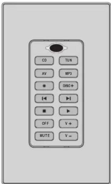
RKP-200
Learning Keypad
natural_image
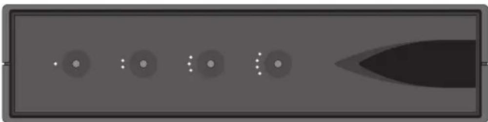
Abstract grayscale diagram with circular and dot patterns, no text or symbols presentRHB-200
Keypad Connecting Hub
1. RKP-200 Keypad
2. RHB-200 Connecting Hub
3. Connecting Keypads
flowchart
graph TD
    A["Switch 1"] --> B["Switch 2"]
    C["Switch 3"] --> D["Switch 4"]
    E["Switch 5"] --> F["Switch 6"]
    G["Switch 7"] --> H["Switch 8"]
    I["Switch 9"] --> J["Switch 10"]
    K["Switch 11"] --> L["Switch 12"]
    M["Switch 13"] --> N["Switch 14"]
    O["Switch 15"] --> P["Switch 16"]
    Q["Switch 17"] --> R["Switch 18"]
    S["Switch 19"] --> T["Switch 20"]
    U["Switch 21"] --> V["Switch 22"]
    W["Switch 23"] --> X["Switch 24"]
    Y["Switch 25"] --> Z["Switch 26"]
    AA["Switch 27"] --> AB["Switch 28"]
    AC["Switch 29"] --> AD["Switch 30"]
    AE["Switch 31"] --> AF["Switch 32"]
    AG["Switch 33"] --> AH["Switch 34"]
    AI["Switch 35"] --> AJ["Switch 36"]
    AK["Switch 37"] --> AL["Switch 38"]
    AM["Switch 39"] --> AN["Switch 40"]
    AO["Switch 41"] --> AP["Switch 42"]
    AQ["Switch 43"] --> AR["Switch 44"]
    AS["Switch 45"] --> AT["Switch 46"]
    AU["Switch 47"] --> AV["Switch 48"]
    AW["Switch 49"] --> AX["Switch 50"]
    AY["Switch 51"] --> AZ["Switch 52"]
    BA["Switch 53"] --> BB["Switch 54"]
    BC["Switch 55"] --> BD["Switch 56"]
    BE["Switch 57"] --> BF["Switch 58"]
    BG["Switch 59"] --> BH["Switch 60"]
    BI["Switch 61"] --> BJ["Switch 62"]
    BK["Switch 63"] --> BL["Switch 64"]
    BM["Switch 65"] --> BN["Switch 66"]
    BO["Switch 67"] --> BP["Switch 68"]
    BQ["Switch 69"] --> BR["Switch 70"]
    BS["Switch 71"] --> BT["Switch 72"]
    BU["Switch 73"] --> BV["Switch 74"]
    BW["Switch 75"] --> BX["Switch 76"]
    BY["Switch 77"] --> BZ["Switch 78"]
    CA["Switch 79"] --> CB["Switch 7A"]
    CC["Switch 80"] --> CD["Switch 81"]
    CE["Switch 81"] --> CF["Switch 82"]
    CG["Switch 82"] --> CH["Switch 83"]
    CI["Switch 83"] --> CJ["Switch 84"]
    CK["Switch 85"] --> CL["Switch 86"]
    CM["Switch 86"] --> CN["Switch 87"]
    CO["Switch 87"] --> CP["Switch 88"]
    CS["Switch 88"] --> CT["Switch 89"]
    CU["Switch 89"] --> CV["Switch 90"]
    CW["Switch 90"] --> CX["Switch 91"]
    CY["Switch 91"] --> CZ["Switch 92"]
    DA["Switch 92"] --> DB["Switch 93"]
    DC["Switch 93"] --> DE["Switch 94"]
    DF["Switch 94"] --> DG["Switch 95"]
    DH["Switch 95"] --> DI["Switch 96"]
    DJ["Switch 96"] --> DK["Switch 97"]
    DL["Switch 97"] --> DV["Switch 98"]
4. Connecting RHB-200
5. Clone setup
flowchart
graph TD
    A["Device 1"] --> B["Switch"]
    C["Device 2"] --> B
    D["Device 3"] --> B
    E["Device 4"] --> B
    F["Device 5"] --> B
    G["Device 6"] --> B
    H["Device 7"] --> B
    I["Device 8"] --> B
    J["Device 9"] --> B
    K["Device 10"] --> B
    L["Device 11"] --> B
    M["Device 12"] --> B
    N["Device 13"] --> B
    O["Device 14"] --> B
    P["Device 15"] --> B
    Q["Device 16"] --> B
    R["Device 17"] --> B
    S["Device 18"] --> B
    T["Device 19"] --> B
    U["Device 20"] --> B
    V["Device 21"] --> B
    W["Device 22"] --> B
    X["Device 23"] --> B
    Y["Device 24"] --> B
    Z["Device 25"] --> B
    AA["Device 26"] --> B
    AB["Device 27"] --> B
    AC["Device 28"] --> B
    AD["Device 29"] --> B
    AE["Device 30"] --> B
    AF["Device 31"] --> B
    AG["Device 32"] --> B
    AH["Device 33"] --> B
    AI["Device 34"] --> B
    AJ["Device 35"] --> B
    AK["Device 36"] --> B
    AL["Device 37"] --> B
    AM["Device 38"] --> B
    AN["Device 39"] --> B
    AO["Device 40"] --> B
    AP["Device 41"] --> B
    AQ["Device 42"] --> B
    AR["Device 43"] --> B
    AS["Device 44"] --> B
    AT["Device 45"] --> B
    AU["Device 46"] --> B
    AV["Device 47"] --> B
    AW["Device 48"] --> B
    AX["Device 49"] --> B
    AY["Device 50"] --> B
    AZ["Device 51"] --> B
    BA["Device 52"] --> B
    BB["Device 53"] --> B
    BC["Device 54"] --> B
    BD["Device 55"] --> B
    BE["Device 56"] --> B
    BF["Device 57"] --> B
    BG["Device 58"] --> B
    BH["Device 59"] --> B
    BI["Device 60"] --> B
    BJ["Device 61"] --> B
    BK["Device 62"] --> B
    BL["Device 63"] --> B
    BM["Device 64"] --> B
    BN["Device 65"] --> B
    BO["Device 66"] --> B
    BP["Device 67"] --> B
    BPB["Device 68"] --> B
    BPC["Device 69"] --> B
    BPD["Device 70"] --> B
Contents
- RKP-200 Keypad 2
- RHB-200 Connecting Hub 2
- Connecting Keypads 3
- Connecting RHB-200 4
- Clone setup 5
Introduction 7
Key Features 7
RKP-200 Overview 7
Device Buttons 27
Command Buttons 47
Multi-function Buttons 37
IR Sensor 1 7
Output Connector 7 7
Input Connector 5 7
DIP Switches 8 7
RESET Button 6 7
RHB-200 Overview 7
Zone LEDs 9 7
Power LED 10 7
Clone Button 11 7
+12V DC input 12 8
Clone Input 13 8
Zone Inputs 14 8
Zone IR Outputs 18
Common IR Outputs 16 8
Connecting the system....8
Cable selection 8
Connecting Master Keypads 7 14 8
Connecting a Second Keypad 5 7 8
Mounting the Keypads 9
Connecting the RHB-200 to a Rotel Receiver 15 9
Connecting the RHB-200 to Source Components 16 9
AC Power connection 5 9
Operating the Keypads....10
Selecting a component 2 3 10
Operating a CD Player 2 3 4 10
Operating a Tuner 2 3 4 10
Operating a DVD Player 2 3 4 10
Operating an MP3 Player 2 3 4 10
Backlighting 2 3 4 11
IR Sensor 1 11
Configuring the keypads....11
Using the DIP switches 8 11
Disabling Backlighting 8 12
Disabling IR Sensor 8 12
Optional Device Buttons 38 12
Learning commands 1 2 3 4 8 13
Learning invisible layer commands 1 2 3 14 8
Programming a SMART Sequence 2 3 4 8 15
Programming a SMART Sequence
with Invisible Layer Commands 2 3 4 8 16
Cloning 9 11 16
Resetting keypads 6 16
Changing buttons 16
Introduction
The RKP-200 Keypad and RHB-200 Connecting Hub provide an integrated system that allows control of Rotel multi-zone systems from wall mounted keypads in remote zones.
Key Features
- Programmed to operate Rotel multi-zone receivers, DVD players, CD players, and AM/FM tuners.
- Learning function to teach the RKP-200 commands from other remotes. Multi-step SMART programming for automatic sequences.
- System allows control from up to four zones.
- Two identically programmed keypads can be installed in each zone.
- Built-in IR sensor allows each keypad to receive commands from a handheld remote.
- Backlighting for use in dark rooms whenever a button is pressed.
- Durable laser-etched buttons with permanent labels. Optional buttons provide alternate labels.
- Cloning feature for easy duplication of the entire command set from one RKP-200 to another.
RKP-200 Overview
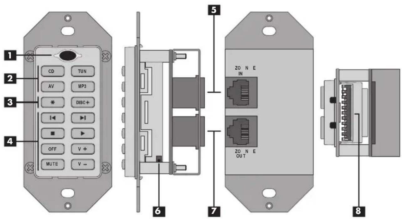
The following describes the features and connections on the RKP-200 keypad.
Device Buttons 2
Four buttons at the top of the keypad are permanently configured as device buttons. Pressing a device button selects the active source input on the multi-zone receiver and changes the function of the command buttons to operate that component.
Command Buttons 4
Eight buttons at the bottom of the keypad are permanently configured as command buttons. Pressing a command button sends an IR signal to operate the selected component.
Multi-function Buttons 3
These two buttons are factory programmed as command buttons. However, they can be optionally reconfigured as device buttons should your system have more than four source components.
IR Sensor 1
An infrared sensor located behind the dark oval lens at the top of the keypad, receives IR commands from a handheld remote control.
Output Connector 7
A modular RJ-45 jack on the back of the keypad connects the first keypad in a zone to the RHB-200 hub with CAT-5 Ethernet-style cables. Also, used to connect the second keypad in a zone to the first.
Input Connector 5
A modular RJ-45 jack on the back of the keypad for connecting a second keypad in a zone.
DIP Switches 8
Ten miniature switches, visible when the keypad is removed from the wall, are used in configuring the keypad.
RESET Button 6
A small button, visible when the keypad is removed from the wall, cancels all learned commands and restores the factory configuration.
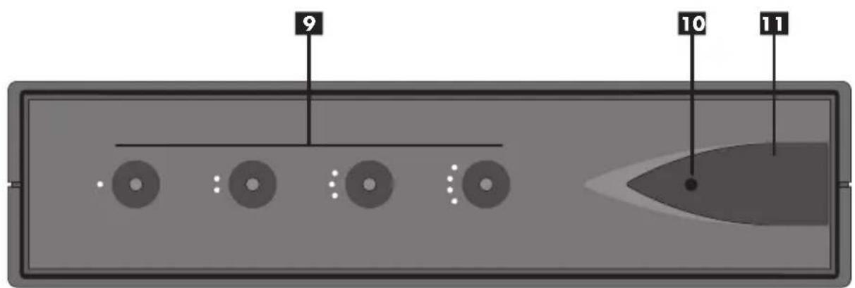
RHB-200 Overview
The following provides a brief description of the features and connections on the RHB-200.
Zone LEDs 9
Four LEDs on the front panel provide status information during cloning of keypads.
Power LED 10
LED near right side of front panel illuminates when the RHB-200 is connected to AC power.
Clone Button 11
Large button at right of front panel. Press to begin cloning during configuration.
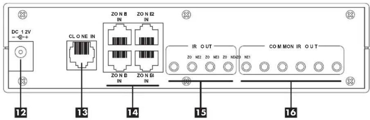
+12V DC input 12
The power connector receives +12V signal when AC power supply is plugged into a wall outlet.
Clone Input 13
RJ-45 modular jack accepts CAT-5 cable from keypad during cloning configuration.
Zone Inputs 14
Four RJ-45 modular jacks accept CAT-5 cables from keypads in up to four zones.
Zone IR Outputs 15
Four 3.5mm mini-jacks send IR signals to the zone IR inputs on a Rotel receiver.
Common IR Outputs 16
Six 3.5mm mini-jacks send IR signals to source components, either to a direct-wired connection (Rotel components) or to an IR emitter.
Connecting the system
Master keypads in up to four remote zones connect to a centrally-located RHB-200 Connecting Hub using standard Category 5 Ethernet-style cabling and 8-pin RJ-45 modular plugs. A second keypad can be added in each of the four zones, if desired. The second keypad is connected to the master keypad in its zone and provides duplicate functions from a second location.
Cable selection
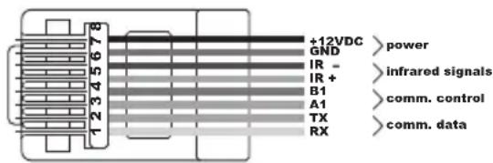
Run 8-conductor CAT-5 Ethernet cabling from each keypad location to the RHB-200 Connecting Hub. Terminate each end of the cables with standard 8-pin RJ-45 modular plugs. Use a "straight-through" wiring code, with the same color wire connected to the same pin on every plug as shown below. If your cable has different color codes, make sure to wire every modular plug in the same order.
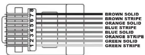
This illustration shows the signals carried by each conductor of the CAT-5 wiring:
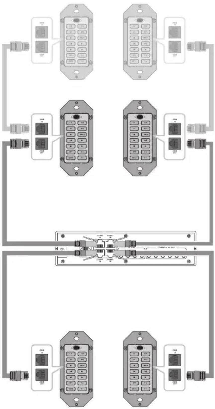
Connecting Master Keypads 7 14
See Figure 3
The first keypad in each zone is designated as the master keypad. All master keypads connect directly to the RHB-200 Connecting Hub as follows.
- For Zone 1, connect one end of the cable to the ZONE OUT modular jack on the back of the master keypad.
- Connect the other end to the ZONE 1 modular jack on the RHB-200 Connecting Hub.
- Repeat for the master keypads in Zones 2, 3, and 4, using the ZONE 2, ZONE 3, and ZONE 4 modular jacks on the RHB-200.
The master keypads are shown in normal shading on the illustration.
Connecting a Second Keypad 5 7
See Figure 3
An optional second keypad in each zone is designated as a slave keypad. Slave keypads always connect to the master keypad in the zone:
- Connect one end of a Category 5 Ethernet cable from the ZONE OUT modular jack on the slave keypad.
- Connect the other end to the ZONE IN jack on the master keypad.
- Repeat for the master keypads in Zones 2, 3, and 4, using the ZONE 2, ZONE 3, and ZONE 4 modular jacks on the RHB-200.
Optional slave keypads are shown in lighter shading on the illustration.
Mounting the Keypads
Once all of the keypads are connected, programmed, and tested, finish the installation by installing them into electrical boxes.
NOTE: Purchase decorative switchplate covers to match those used in the room for light switches. The RKB-200 is not supplied with decorative switch plate covers because there is no way to know which style or color will match in custom installations.
The exact installation steps may vary depending on the style of switch plate covers you purchase. However, here is a typical installation method using Decora® style covers:
- Remove the mounting bracket from the back of the decorative cover.
- Place the mounting bracket over the electrical box.
- Place the keypad through the mounting bracket and into the electrical box.
- Place two screws through the mounting tabs on the keypad and through the mounting bracket to secure the keypad. Do not overtighten.
- Place the decorative cover over the keypad and press in at the top and bottom until secure. There is a small slot in one edge of the decorative cover. Orient the cover so this slot is facing down.
NOTE: Do not mount the keypads until all programming steps are complete and the system has been tested. Access to DIP switches at the back of the keypads is necessary during programming.
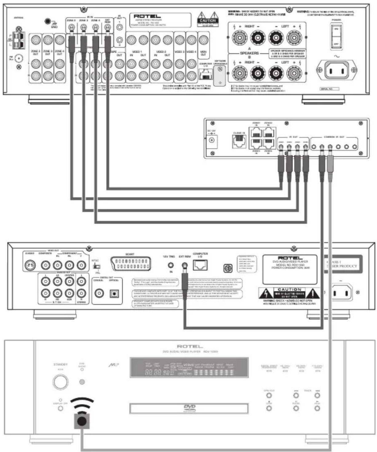
Connecting the RHB-200 to a Rotel Receiver 15
See Figure 4
The RHB-200 connecting hub sends command codes to a Rotel multi-zone receiver using infrared commands. The connections are made using two-conductor cables with 3.5mm mono mini plugs on both ends. One cable is needed for each zone with a keypad, up to a max of four. A Rotel RX-1052 multi-zone receiver is shown in the example:
-
Plug one end of the first cable into the ZONE 1 IR OUT connector on back of the RHB-200.
-
Plug the other end of the cable into the zone 1 IR input on the receiver, labeled EXT REM IR IN on the Rotel RX-1052.
- Repeat for any additional zones, matching the ZONE 2 IR OUT on the RHB-200 to the ZONE 2 IR IN on the receiver, etc.
Connecting the RHB-200 to Source Components 16
See Figure 4
The RHB-200 connecting hub sends command codes to source components (such as CD players) using infrared commands. With most Rotel source components, connections are made using two-conductor cables with 3.5mm mono mini plugs on both ends. One cable is needed for each source component.
- Plug one end of the cable for the first Rotel source component into any of the COMMON IR OUT connectors on back of the RHB-200.
- Plug the other end of the cable into the EXT REM IN IR input on first source component.
- Repeat for any source components, using any available COMMON IR OUT connectors on the RHB-200.
NOTE: If your source component does not have an input for a hard-wired IR cable, you can use an industry standard IR emitter placed in front of the source component's infrared remote sensor. Connect the other end of cable to a COMMON IR OUT connector on the RHB-200. This type of source component is shown at the bottom of Figure 4.
AC Power connection 5
Once all of the keypad and IR connections are complete, supply power to the RHB-200.
- Plug the connector from the supplied AC adaptor into the +12V input on the back of the RHB-200.
- Plug the AC adaptor into an AC power wall outlet.
Operating the Keypads
The keypads are preprogrammed to operate the Rotel RX-1052 multi-zone receiver and the following source components:
Rotel CD Players:
RCD-1072 & RCC-1055
Rotel Tuner:
RX-1052 built-in tuner
Rotel DVD Player:
RDV-1092/RDV-1060
MP3 Players:
Navipod and the most popular brands of portable players
Although the keypads can be customized with learned commands, there is no need to do so when used with components listed above.
Selecting a component 2 3
Press one of the four standard device buttons (CD, TUN) to select that source component as the input for the zone. Once you have selected the component, use the 10 command buttons to operate the component you have selected as described below.
NOTE: If you choose to customize the keypads, two more buttons (*and) can be used as additional device buttons.
Operating a CD Player 2 3 4
Press the CD button to select the CD player. A SMART sequence automatically starts disc playback. The following commands are available:
CD Select CD input and begin play
* Random Play
DISC+ Select Disc (changers only)
Track Backward
Track Forward
■ Stop
Play
OFF Turn off zone and backlighting
MUTE Mute sound
v+ Increase volume
v- Reduce volume
Operating a Tuner 2 3 4
Press the TUN button to select the AM/FM tuner. The following commands are available:
TUN Select tuner input
* Tuner Preset #1
DISC+ Tune Up
▶ Tune Down
Preset Up
▶ Preset Down
■ Preset Scan
OFF Turn off zone and backlighting
MUTE Mute sound
v+ Increase volume
v- Reduce Volume
Operating a DVD Player 2 3 4
Press the AV button to select the DVD input. The following commands are available:
AV Select VIDEO 1 input
* No command
DISC+ No command
Play
Track backward
Track forward
■ Stop
OFF Turn off zone and backlighting
MUTE Mute sound
v+ Increase volume
v- Reduce volume
Operating an MP3 Player 2 3 4
Press the MB button to select the MP3 input. The following commands are available:
MP3 Select VIDEO 2 input
* Shuffle play
DISC+ Next playlist
Play/Pause
Previous song
▶ Next song
Play/Pause
OFF Turn off zone and backlighting
MUTE Mute sound
v+ Increase volume
v- Reduce volume
Backlighting 2 3 4
As delivered from the factory, the keypads have automatic backlighting for the device buttons and the MBUBon.
When a device button is pressed, the backlighting for that button remains lit to indicate the currently selected device.
The backlighting for the Button remains on when the sound is muted. The backlighting turns off when the Button is pressed again or when muting is cancelled by pressing the V button - buttons.
All backlighting is turned off when the button is pressed and remains off until a device button is pressed.
NOTE: The backlighting feature can be permanently disabled during configuration of the keypads.
IR Sensor 1
An infrared sensor is located behind the dark oval lens at the top of the keypad. This sensor receives IR commands from a handheld remote control aimed at the keypad.
IR commands received by the IR sensor do not change the backlighting on the keypad. For example, a MUTE command received from a handheld remote will not light the MUTE button on the keypad.
MUTE: The IR sensor can be disabled during configuration of the keypads. Generally, the sensor of a second keypad in a zone should be disabled if there is a chance of IR signals reaching both keypads simultaneously.
Configuring the keypads
With the default factory configuration, the keypads are ready to use in a system with Rotel components as described in the Operating the Keypads section of the manual. However, the keypads can be customized in several ways during setup. Options include:
- Learning commands from handheld remote controls in place of the existing commands.
- Combining the commands in a SMART sequence that is sent whenever a device is selected.
- Using two additional buttons as device keys, for a total of six available source components.
- Disabling the infrared sensor on the front of the keypad.
- Disabling the backlighting.
- Resetting the keypad to its default factory configuration.
- Replacing the standard button labels with optional labels.
This section of the manual provides instructions for each of these configuration steps.
NOTE: An additional customizing feature is Cloning, which allows quick transfer of learned commands and SMART sequences to additional keypads. Cloning is covered in a later section of the manual.
Using the DIP switches 8
All of the configuration options require the use of small DIP switches located on the bottom of the keypad. These switches are only accessible before the keypad is mounted in an electrical box. Therefore, customizing should be completed before mounting the keypads.
The location of the DIP switches can be seen in Figure 1 at the front of this manual. Here are the default settings for all ten switches:

Details of the switch settings are provided with the instructions for each configuration option, but here is a summary:
SW1: Used for invisible layer command programming for the CD device.
SW2: Used for invisible layer command programming for the TUN device.
SW3: Used for invisible layer command programming for the AV device.
SW4: Used for invisible layer command programming for the MP3 device.
SW5: In the ON position, enables the button as an additional device key.
SW6: In the ON position, enables the button as an additional device key. DISC+
SW7: Enables the learning mode in the ON position.
SW8: Enables the SMART programming mode in the ON position.
SW9: Enables (ON) or disables (OFF) the IR sensor on the front of the keypad.
SW10: Enables (ON) or disables (OFF) the backlighting feature.
Disabling Backlighting 8
The RKP-200 backlighting feature illuminates a device button as a reminder of the selected device as well as the MUTEbutton when the sound is muted.
SW10 configures the backlighting mode:
To enable the backlighting, put SW10 in the ON position.

To disable the backlighting, put SW10 in the OFF position.

NOTE: Flashing button illumination provides confirmation and error indications during the Learning and SMART sequence programming. The backlighting should be enabled during configuration.
Disabling IR Sensor 8
An IR sensor on the front of the keypad allows operation of the system from a handheld remote control aimed at the keypad. This sensor can be disabled. Generally, the sensor only needs to be disabled when two keypads are installed in the same room. In this case, disable the sensor on the second keypad to prevent sending IR commands to both keypads. For the same reason, you might disable the sensor of a keypad installed near the components being controlled.
SW9 configures the sensor mode:
To enable the IR sensor, put SW9 in the ON position.

To disable the IR sensor, put SW9 in the OFF position.

NOTE: Learning commands is done by aiming a handheld remote at the keypad sensor. The sensor must be enabled during Learning configuration.
Optional Device Buttons 3 8
The keypad has four permanent device buttons: CD, TUN AT These device buttons select a source component for listening and operation. Pressing a device button makes the normal commands on the other ten buttons available. Device buttons cannot store normal learned commands; however, they can store a SMART sequence of normal commands that is sent when the device button is pressed.
The RKP-200 provides the option of designating the *and/or the DISCHons as additional device buttons. SW5 configures the *button. SW6 configures the DISCHon.
To make* the only additional device button, put SW5 in the ON position:

To make Dthe only additional device button, put SW6 in the ON position:

To make both *and additional device buttons, put both SW5 and SW6 in the ON position:

For no additional device buttons, put both SW5 and SW6 in the OFF position:

Learning commands 1 2 3 4 8
The RKP-200 keypad is programmed at the factory with basic commands for Rotel and other components as described in the Operating the Keypads section of the manual. These commands can be replaced when using non-Rotel components or for access to different features.
New commands are learned by the keypad by using a learning procedure during initial configuration of the keypad involving aiming the handheld remote for the component at the IR sensor on the keypad.
The four device buttons ( , CD , TUNAV MP3 not be used to learn commands. In addition, you should not learn new commands replacing the OFF MUTE, V and commands. Therefore, there are six buttons available for learning. These buttons can store commands for each of the devices, ten commands for the C device, ten for the TUN device, etc. Overwriting commands for a device will not change the existing commands for any of the other devices.
If you have designated * and/or DISC device buttons (SW5 and/or SW6 in the ON position), these buttons cannot be used to learn commands. However, they can be used as device buttons with commands learned on other buttons, just like the four standard device buttons (CD, TUN AW MP3
In addition to learning commands on standard buttons, each of the four main device button ,TUN AV, MP3) can store 14 invisible layer commands. These commands cannot be used during normal system operation from the keypad; however, they can be used as part of Smart Macro sequences. The procedure for learning these invisible layer commands is described in the next section.
In this example of learning standard commands, we will change the command for the DISButton for the device to a PAUSE command instead of the original NEXT DISC command. To learn the new command:
- The MUTE button lighting flashes to confirm successful or failed learning. So, the backlighting feature must be active before starting the learning procedure (SW10 in the ON position). Also, the IR sensor must be enabled (SW9 in the ON position). Confirm the position of SW9 and SW10:

-
Press the device key containing the commands (the c button in this example).
-
Put the keypad into Learning mode by moving SW7 to the ON position:

- Within 30 seconds, press the keypad command button that you wish to learn (in this example, the DISC+ button). The backlighting on the MUTE button turns on and the keypad is ready to receive the IR code. It will flash six times if an improper button is pressed (for example, a device button that cannot be learned).
14 RKP-200/RHB-200
-
Aim the handheld remote at the oval sensor on 2 the front of the keypad from a distance of approximately 1 inch (25 mm). Press and hold the button on the handheld remote with the command to be learned (the PAUSE button, in this example).
-
If the command is successfully learned, thenute button will flash twice. Six flashes indicate that the learning failed. If the learning failed, repeat from Step 4.
-
To learn additional commands, repeat from Step 4, pressing the next keypad button to be learned.
-
Exit Learning mode by setting SW7 to the OFF position:

Learning invisible layer commands 1 2 3 4 8
Each of the four devices (CD, TUN) on the 3 RKP-200 keypad can store 14 invisible layer commands. These commands cannot be accessed during normal operation of the keypads; however, they can be used as part of Smart Macro sequences.
The procedure for learning an invisible layer command is similar to learning a standard command, except that four switches SW1 – SW4 are used to select the invisible layer, one switch corresponding to each device. Once the invisible layer is selected, any of the 14 buttons can be used to store an invisible layer command without overwriting the standard commands stored for each button. With an invisible layer for each of the four devices, a total of 56 invisible layers commands can be stored, 14 for each device
To learn an invisible layer command:
-
The M button lighting flashes to confirm successful or failed learning. So, the backlighting feature must be active before starting the learning procedure (SW10 in the ON position). Also, the IR sensor must be enabled (SW9 in the ON position). Confirm the position of SW9 and SW10:
-
Select the device where you want to store the invisible layer command by placing one (and only one) of switches SW1 – SW4 in the ON position, as follows.
To learn invisible layer commands for the CD device, place SW1 in the ON position:

To learn invisible layer commands for the TUN device, place SW2 in the ON position:

To learn invisible layer commands for the AV device, place SW3 in the ON position:

To learn invisible layer commands for the MP3 device, place SW4 in the ON position:

To learn standard commands, exit the invisible layer mode by putting SW1 - SW4 all in the OFF positions. :

- Put the keypad into Learning mode by moving SW7 to the ON position. In this example, we are learning invisible layer commands for the CD device:


-
Within 30 seconds, press the keypad command button that you wish to learn (in this example, the button). The backlighting on the MUTE button turns on and the keypad is ready to receive the IR code. It will flash six times if an improper button is pressed (for example, a device button that cannot be learned).
-
Aim the handheld remote at the oval sensor on the front of the keypad from a distance of approximately 1 inch (25 mm). Press and hold the button on the handheld remote with the command to be learned (the PAUSE button, in this example).
-
If the command is successfully learned, thenute button will flash twice. Six flashes indicate that the learning failed. If the learning failed, repeat from Step 4.
-
To learn additional commands, repeat from Step 4, pressing the next keypad button to be learned.
-
Exit Learning mode by setting SW7 to the OFF position. Then, exit invisible layer mode by returning SW1 - SW4 to the off positions.

Programming a SMART Sequence 2 3 4 8
The four standard device buttons (CD, TUN) AV MP3 and the two optional device buttons (and/or DISC+) can store a sequence of commands to be sent when the device button is pressed. For example, the device button is programmed to switch the Rotel receiver to the CD input and begin disc play.
You can store a new SMART sequence for any device button using the following procedure. In this example, we will program the A device button to select the DVD input, pause for 2 seconds, and begin disc play.
The MUTE button lighting flashes to confirm successful SMART programming. The backlighting feature must be active before starting (SW10 in the ON position).

Put the keypad into SMART programming mode by moving SW8 to the ON position. Make sure that SW7 is OFF.

-
Within 30 seconds, press the keypad device button where you wish to store the SMART sequence (in this example, the button). The backlighting on the MUTE button flashes twice.
-
Press the first step of the SMART sequence. In this example, press the AV button, since the first step is to select the DVD input.
-
Press the next step in the SMART sequence. In this case, add a two second delay by pressing the v+ button twice. This is a special command; each press adds a one second delay.
-
Press the next command in the sequence. In this case, the ▶ button, since the final step in the sequence is to start DVD disc playback. Up to 20 steps can be saved in a sequence. Each one second delay counts as one step.
-
Exit SMART mode by setting SW8 to the OFF position:

Programming a SMART Sequence with Invisible Layer Commands 2 3 4 8
To include invisible layer commands in a SMART sequence, substitute the following steps for Step 4 in the preceding instructions:
- Put SW1, SW2, SW3, or SW4 in the ON position to select the invisible layer where the desired command is stored:

- Press the invisible layer command button.
- Return the SW1 – SW4 switch to the OFF position to exit invisible layer mode.

Cloning

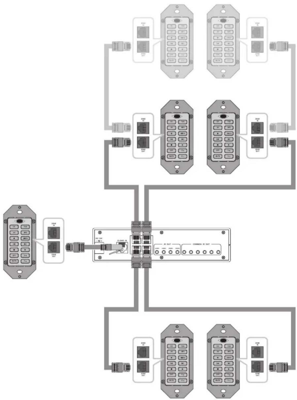
Once you have completed the learning and SMART sequence programming for one keypad, it is easy to transfer that programming to all of the keypads connected to the RHB-200 with a procedure called cloning.
To clone a keypad:
- With the RHB-200 disconnected from the AC wall power, connect the ZONE OUT connector of the programmed keypad to the CLONE IN modular jack on the back of the RHB-200 using a CAT 5 cable.
- Make sure that all keypads to be programmed are connected properly as shown in Figure 5. You can program two keypads in a single zone as shown by light shaded keypads in the illustration.
NOTE: Keypads in the remote zones must not be in Learning or SMART configuration mode.
-
Power on the RHB-200 by connecting it to the AC power source. The four Zone LEDs on the front of the RHB-200 flash green once. The MUTE LED on the keypad being cloned flashes once.
-
Press the large CLONE button on the front panel of the RHB-200. The cloning process begins in sequence, starting with the first key-
pad in ZONE 1. While this keypad is receiving cloned data, the ZONE 1 LED on the front of the RHB-200 flashes red. When the cloning of the first keypad is complete, the LED glows solid red. The cloning process then continues to the second keypad in ZONE 1 (if it exists). The LED flashes green during the cloning and glows solid green when the cloning is complete.
- Step 5 is then repeated automatically for Zone 2, Zone 3, and Zone 4 as necessary. The entire cloning process can take up to 10 minutes.
- If an error occurs, all four LEDs on the RHB-200 flash green six times and the DEVICE buttons on the zone keypads flash on for one second.
Resetting keypads 6
Should you want to reset a keypad to its original factory programming, use a small pointed object to press the reset button on the side of the keypad. This erases all learned commands and SMART sequences.
Changing buttons
A selection of replacement buttons is available from Rotel to customize keypads. To replace buttons:
- Press the two tabs at the top and bottom of the keypad and pull the keypad module from the mounting bracket:
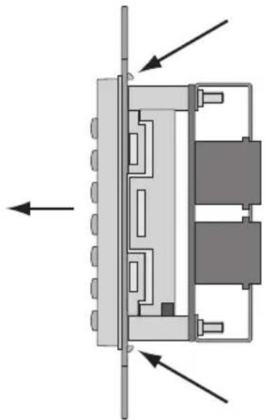
natural_image
Diagram of a mechanical or electrical component with directional arrows indicating movement or force (no text or symbols present)- Using a small flat blade screwdriver, release the four tabs on the sides of the module, releasing the keypad cover.
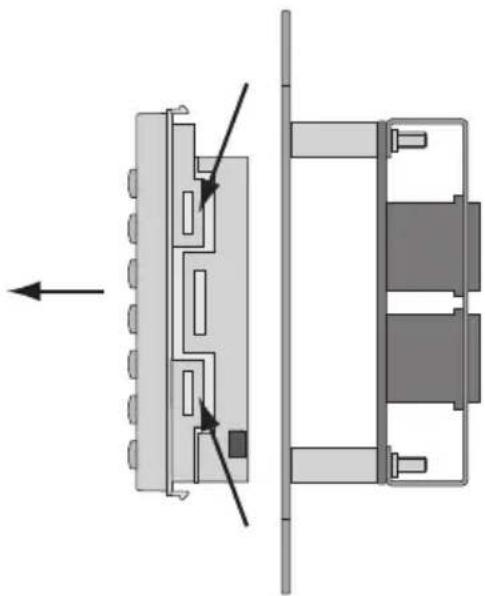
natural_image
Diagram of a mechanical assembly showing two views of a component with arrows indicating direction (no text or symbols present)- Once the keypad cover has been removed, pull a button off and replace it with one of the optional buttons.
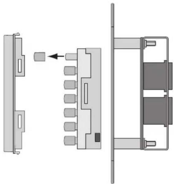
natural_image
Technical diagram showing three views of a mechanical or electronic component assembly (no text or symbols present)
natural_image
Close-up of a printed circuit board with various electronic components and connectors (no readable text or symbols)
The Rotel Co. Ltd.
10-10 Shinsen-Cho
Shibuya-Ku
Tokyo 150-0045
Japan
Phone: +81 3-5458-5325
Fax: +81 3-5458-5310
Rotel of America
54 Concord Street
North Reading, MA 01864-2699
USA
Phone: +1 978-664-3820
Fax: +1 978-664-4109
Rotel Europe
Dale Road
Worthing, West Sussex BN11 2BH
England
Phone: +44 (0)1903 221600
Fax: +44 (0)1903 221525
Rotel Deutschland
Kleine Heide 12
- RKP-200 Keypad
- RHB-200 Connecting Hub
- Connecting Keypads
- Connecting RHB-200
- Clone setup
- Contents
- Introduction
- Key Features
- RKP-200 Overview
- Device Buttons 2
- Command Buttons 4
- Multi-function Buttons 3
- IR Sensor 1
- Output Connector 7
- Input Connector 5
- DIP Switches 8
- RESET Button 6
- RHB-200 Overview
- Zone LEDs 9
- Power LED 10
- Clone Button 11
- +12V DC input 12
- Clone Input 13
- Zone Inputs 14
- Zone IR Outputs 15
- Common IR Outputs 16
- Connecting the system
- Cable selection
- Connecting Master Keypads 7 14
- Connecting a Second Keypad 5 7
- Mounting the Keypads
- Connecting the RHB-200 to a Rotel Receiver 15
- Connecting the RHB-200 to Source Components 16
- AC Power connection 5
- Operating the Keypads
- Rotel CD Players:
- Rotel Tuner:
- Rotel DVD Player:
- MP3 Players:
- Selecting a component 2 3
- Operating a CD Player 2 3 4
- Operating a Tuner 2 3 4
- Operating a DVD Player 2 3 4
- Operating an MP3 Player 2 3 4
- Backlighting 2 3 4
- Configuring the keypads
- Using the DIP switches 8
- Disabling Backlighting 8
- Disabling IR Sensor 8
- Optional Device Buttons 3 8
- Learning commands 1 2 3 4 8
- RKP-200/RHB-200
- Learning invisible layer commands 1 2 3 4 8
- Programming a SMART Sequence 2 3 4 8
- Programming a SMART Sequence with Invisible Layer Commands 2 3 4 8
- Cloning
- Resetting keypads 6
- Changing buttons
- The Rotel Co. Ltd.
- Rotel of America
- Rotel Europe
- Rotel Deutschland
Brand : ROTEL
Model : RHB-200
Category : Remote control