
1730DD - Dimmer JUNG - Free user manual and instructions
Find the device manual for free 1730DD JUNG in PDF.


| Product Type | Standard rotary dimmer LED |
| Model | 1730DD (Art. no.: 1730DD) |
| Brand | JUNG |
| Rated Voltage | AC 230 V~ |
| Mains Frequency | 50/60 Hz |
| Standby Power | Approx. 0.35 W |
| Power Loss | Approx. 2 W |
| Ambient Temperature | -5 ... +45 °C |
| Connected Load (LED/CFL at 25°C) | 20 ... 210 W (ohmic-capacitive), 20 ... 210 VA (ohmic-inductive); HV-LED & CFL: typ. 3 ... 60 W each |
| Dimming Principles | Leading edge or trailing edge phase control (automatic detection) |
| Special Functions | Soft start, last brightness memory, switch-on brightness save, minimum brightness setting, electronic short-circuit and overheat protection |
| Mounting | In appliance box according to DIN 49073 |
| Operation without Neutral | Possible (min. load 50 W, excludes HV-LED/CFL) |
| Power Extension | Possible via power boosters |
| Clampable Conductor Cross-section | 1x 0.5-4 mm², 2x 0.5-2.5 mm² or 2x 0.5-1.5 mm² |
| Total Power Cable Length | Max. 100 m |
| Power Reduction per 5°C above 25°C | -10% |
| Power Reduction in Wood/Drywall | -15% |
| Power Reduction in Multiple Combinations | -20% |
| Accessories | Compensation module LED (Art. no.: KMLED230U) |
| Safety | Danger of electric shock; device not suitable for disconnection; fuse inductive transformers per manufacturer |
| Warranty | According to legal framework, via specialty store |
Frequently Asked Questions - 1730DD JUNG
User questions about 1730DD JUNG
0 question about this device. Answer the ones you know or ask your own.
Ask a new question about this device
Download the instructions for your Dimmer in PDF format for free! Find your manual 1730DD - JUNG and take your electronic device back in hand. On this page are published all the documents necessary for the use of your device. 1730DD by JUNG.
USER MANUAL 1730DD JUNG
Standard rotary dimmer LED
Art. no.: 1730DD
Operating instructions
1 Safety instructions

Electrical devices may only be mounted and connected by electrically skilled persons.
Serious injuries, fire or property damage possible. Please read and follow manual fully.
Danger of electric shock. Always disconnect before carrying out work on the devise or load.
Danger of electric shock. Device is not suitable for disconnection from supply voltage. The load is not electrically isolated from the mains even when the device is switched off.
Risk of destruction if the set operating mode and load type do not match. Set correct operating mode when connecting or exchanging the load.
Fire hazard. For operation with inductive transformers, each transformer must be fused on the primary side in accordance with the manufacturer's instructions. Only safety transformers according to EN 61558-2-6 may be used.
These instructions are an integral part of the product, and must remain with the end customer.
2 Intended use
– Switching and dimming of lighting
– Mounting in appliance box according to DIN 49073
– Operation with suitable cover
3 Product characteristics
Product characteristics
– Device works according to the leading edge phase control or trailing edge phase control principle
– Automatic setting of the dimming principle suitable for the load
– Operation without neutral conductor possible
– Switch-on via bulb-preserving soft start
- Switch on with last saved brightness or saved switch-on brightness
– Switch-on brightness can be saved permanently
– Minimum brightness can be saved permanently
– Electronic short-circuit protection with permanent switch-off after 7 seconds at the latest
– Electronic over-temperature protection
i Power extension possible by means of power boosters.
4 Operation
Switching light or adjusting brightness
flowchart
graph TD
    A["Start"] --> B{Decision}
    B -->|Yes| C["Process Step"]
    B -->|No| D["End"]
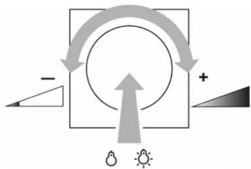
Figure 1: Switching light or adjusting brightness
■ Press the setting knob briefly: Light switches on or off (Figure 1).
■ Turn the setting knob quickly: Brightness is changed quickly (Figure 1).
■ Turn the setting knob slowly: Brightness is changed slowly (Figure 1).
Switching the light on at minimum or maximum brightness
flowchart
graph TD
    A["1. Light icon"] --> B["2. Grey arrow"]
    B --> C["3. Max. Sun icon"]
    style A fill:#f9f,stroke:#333
    style B fill:#ccf,stroke:#333
    style C fill:#cff,stroke:#333
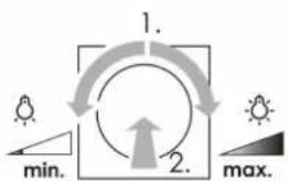
Figure 2: Switching on the light at minimum or maximum brightness
■ Turn the setting knob by a quarter turn, then press the setting knob briefly: Light switches on at minimum brightness or maximum brightness (Figure 2).
Save switch-on brightness
■ Adjust the brightness.
■ Press the setting knob for longer than 4 seconds.
Switch-on brightness is saved. The lighting switches briefly off and on again as confirmation.
Delete switch-on brightness
■ Press the setting knob briefly: Light switches on at the saved switch-on brightness.
■ Press the setting knob for longer than 4 seconds.
The switch-on brightness is deleted. Switching on takes place at the last brightness value set. For confirmation, the light is switched off briefly and switched on again.
5 Information for electrically skilled persons
5.1 Fitting and electrical connection

DANGER!
Mortal danger of electric shock.
Disconnect the device. Cover up live parts.
Fitting and electrical connection
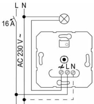
Figure 3: Connection diagram
Connect 600 Watt LED lamps or compact fluorescent lamps at most per 16 ampere circuit breaker. When connecting transformers, observe the data of the transformer manufacturer.
Our dimmers take into account the different electronic characteristics of most LED lamps found on the market. However, it cannot be guaranteed that in individual cases the desired results may not be achieved.
Operation without neutral conductor possible.
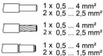
Figure 4: Clampable conductor cross-section
Reset the overheating protection / short-circuit protection
If the electronic overheating or short-circuit protection has been activated, separate the dimmer from the grid.
5.2 Commissioning
Setting the minimum brightness
Precondition: The dimmer is ready for operation and the load is switched off.
■ Press the setting knob for approx. 10 to 15 seconds until the light switches on and off again.
■ Press again and hold the knob within 5 seconds. Light switches on at the lowest brightness and slowly becomes brighter.
i In the lowest dimming position, a lamp light must be visible.
■ Once the desired minimum brightness is reached, release the setting knob. The minimum brightness is stored and the light is switched off.
6 Technical data
Rated voltage AC 230 V\~
Mains frequency 50 / 60 Hz
Standby power approx. 0.35 W
Power loss approx. 2 W
Ambient temperature -5 ... +45 °C
Connected load at 25 °C (Figure 5)
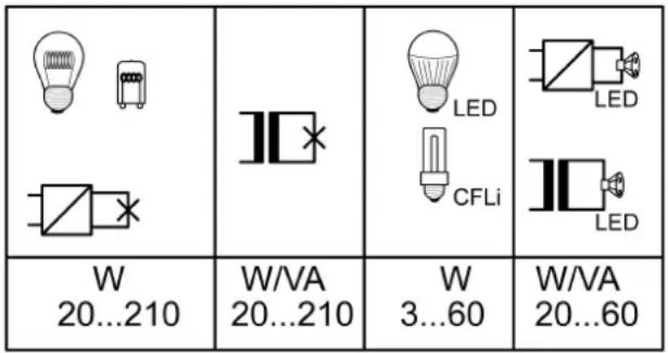
Figure 5: Connected load
Mixed load
ohmic-capacitive 20 ... 210 W
capacitive-inductive not permitted
ohmic-inductive 20 ... 210 VA
Ohmic and HV LED typ. 3 ... 60 W
Ohmic and compact fl lamp. typ. 3 ... 60 W
If the dimmer is adjusted to trailing edge phase control, the maximum connected load for HV-LED lamps is typ. 3 ... 120 W and electronic transformers with LV-LED lamps typ. 20 ... 120 W.
i Power specifications including transformer dissipation.
i Operate inductive transformers with at least 85% nominal load.
☐ Ohmic-inductive mixed load: maximum 50% proportion of ohmic load. Otherwise, an incorrect measurement is possible.
Operation without neutral conductor: Minimum load 50 W. Does not apply to loads with HV-LED and compact fluorescent lamps.
Power reduction
per 5°C in excess of 25°C -10%
when installed in wooden or dry construction walls -15%
when installed in multiple combinations -20%
Power boosters See power booster instructions
Total length power cable max. 100 m
7 Troubleshooting
Connected LED lamps or compact fluorescent lamps switch off in the lowest dimming position or flicker
Cause: The set minimum brightness is too low.
Increase minimum brightness.
Connected lamps do not switch on in the lowest dimming position or only after a delay
Cause: The set minimum brightness is too low.
Increase minimum brightness.
Connected LED lamps or compact fluorescent lamps flicker or buzz, no correct dimming possible, device buzzes
Cause 1: Lamps are not dimmable.
Check manufacturer's instructions.
Exchange lamps for another type.
Cause 2: Dimmer is connected without neutral conductor.
Connect neutral conductor if possible, otherwise exchange lamp for another type.
Connected LED lamps or compact fluorescent lamps in the lowest dimming position are too bright; dimming range is too small
Cause 1: The set minimum brightness is too high.
Reduce minimum brightness.
Exchange HV-LED lamps for another type.
The dimmer switches the load off briefly and then on again.
Cause: short-circuit protection has tripped but now there is no longer a fault.
The dimmer has switched off and the load cannot be switched on again
Cause 1: overheating protection has tripped.
Disconnect dimmer from mains by switching off circuit breaker.
Reduce the connected load. Exchange lamps for another type.
Let dimmer cool down for at least 15 minutes.
Switch circuit breakers and dimmer on again.
Cause 2: Surge protection has triggered.
Exchange lamps for another type.
Cause 3: short-circuit protection has tripped.
Disconnect dimmer from mains by switching off circuit breaker.
Eliminate short-circuit.
Switch circuit breakers and dimmer on again.
i Short-circuit protection is not based on a conventional fuse, no metallic separation of the operational current.
Cause 4: load failure.
Check load, replace light bulb. For inductive transformers, check primary fuse.
LED lamp is dimly lit when dimmer is switched off
Cause: LED lamp is not suitable for this dimmer.
Use a compensation module, see accessories.
Use another type of LED lamp or an LED lamp of another manufacturer.
8 Accessories
Compensation module LED Art. no. KMLED230U
9 Warranty
The warranty follows about the specialty store in between the legal framework as provided for by law
ALBRECHT JUNG GMBH & CO. KG
Vollmestraße 1
58579 Schalksmühle
GERMANY
Telefon: +49 2355 806-0
Telefax: +49 2355 806-204
kundencenter@jung.de
www.jung.de
Brand : JUNG
Model : 1730DD
Category : Dimmer