
ELVOX 4621.2812ESA - Camera Vimar - Free user manual and instructions
Find the device manual for free ELVOX 4621.2812ESA Vimar in PDF.


| Product Type | IP Camera (Fisheye model) |
| Brand | Vimar (ELVOX series) |
| Model | 4621.2812ESA |
| Image Sensor | High-performance CMOS sensor |
| Max Resolution | 2592x1520 (5MP) at 25fps (main stream) |
| Video Compression | H.265/H.264 (Main/High/Baseline Profile) |
| Lens Type | Fisheye lens (360° panoramic view) |
| Streams | Triple stream (main, sub, third) |
| Network Interface | 10/100 Mbps Ethernet (RJ45) |
| Power Supply | DC 12V or PoE (IEEE 802.3af) |
| Power Consumption | Approx. 7W (typical) |
| Dimensions (WxHxD) | Approx. 100 x 100 x 50 mm (estimated for dome) |
| Weight | Approx. 250 g (estimated) |
| Storage | MicroSD card slot (up to 128GB, class 10) |
| Remote Access | IE browser (ActiveX), IP-Tool, App (CVM ELVOX) |
| PTZ Control | Digital PTZ via fisheye dewarping (4 PTZ windows) |
| Alarm Input/Output | 1x Alarm In (NO/NC), 1x Alarm Out (relay) |
| Audio | Built-in mic, audio line in, speaker out (G.711U/A) |
| Infrared | Automatic IR cut filter, IR LEDs for night vision (range approx. 20m) |
| Weather Rating | Indoor use only (no IP rating specified) |
| Security | HTTPS, 802.1x, IP/MAC filtering, user authentication, ONVIF |
| Operating Temperature | 0°C to 40°C (32°F to 104°F) |
| Maintenance | Clean with soft dry cloth; do not use corrosive cleaners |
Frequently Asked Questions - ELVOX 4621.2812ESA Vimar
User questions about ELVOX 4621.2812ESA Vimar
0 question about this device. Answer the ones you know or ask your own.
Ask a new question about this device
Download the instructions for your Camera in PDF format for free! Find your manual ELVOX 4621.2812ESA - Vimar and take your electronic device back in hand. On this page are published all the documents necessary for the use of your device. ELVOX 4621.2812ESA by Vimar.
USER MANUAL ELVOX 4621.2812ESA Vimar
Gestione telecamera IP
IP camera management
Gestione telecamera IP
Gestione telecamera IP
1 - Introduzione
Gestione telecamera IP
Gestione telecamera IP
flowchart
graph LR
    A["IPC"] -->|Network Cable| B["Router"]
    B -->|Network Cable| C["Client"]
    C -->|Network Cable| B
Gestione telecamera IP
Gestione telecamera IP
Gestione telecamera IP
Solo per telecamera fisheye:
Gestione telecamera IP
Gestione telecamera IP
Gestione telecamera IP
Gestione telecamera IP
Gestione telecamera IP
4.2.2 - Flusso video
natural_image
Aerial view of a car driving on a multi-lane road surrounded by greenery (no visible text or symbols)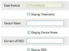
Solo per telecamera fisheye:
natural_image
Fisheye lens view of a smart home control room with multiple rooms and equipment (no visible text or symbols)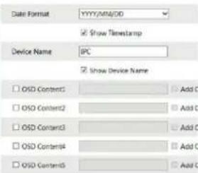
Gestione telecamera IP
4.2.4 - Maschera video
Solo per telecamera fisheye:
natural_image
Fisheye view of a circular office workspace with multiple desks and chairs, no visible text or symbols on the main scene.natural_image
Overhead fisheye view of a busy office workspace with multiple workstations and employees (no visible text or symbols)Cancellare la maschera video:
natural_image
Aerial view of a multi-lane urban street with cars and trees, no visible text or symbols.Solo per telecamera fisheye:
natural_image
Fisheye view of an office interior with cubicles and desks, no visible text or symbolsGestione telecamera IP
Gestione telecamera IP
Solo per telecamera fisheye:
Gestione telecamera IP
4.4.3 - Errore SD card
Gestione telecamera IP
Gestione telecamera IP
4.4.7 - Alarm Out
4.4.9 Allarme audio
OK
Gestione telecamera IP
4.5.4 - Onvif
Gestione telecamera IP
Gestione telecamera IP
4.5.7 - 802.1x
Gestione telecamera IP
Gestione telecamera IP
4.5.12 - HTTPS
Gestione telecamera IP
4.5.113 - QoS
Andare a Config - Security.
| Add | Modify | Delete | |
| Index | User Name | User Type | Binding MAC |
| 1 | admin | Administrator |
Gestione telecamera IP
Andare a Config → Security — Elenchi Block e Allow.
IP Address Filter Setting
√ Enable IP address filtering
Block the following IP address Allow the following IP address
Block the Following MAC Address
Enable MAC address filtering
Block the following MAC address Allow the following MAC address
Gestione telecamera IP
natural_image
Street scene with cars and a damaged car on a wet road, surrounded by trees (no visible text or symbols)Gestione telecamera IP
5.3 - Ricerca video in SD card
IP camera management
Table of Contents - Notes on Safety
1 - Introduction .... 37
2 - IE Remote Access....38
2.1 - LAN 38
2.1.1 - Access through IP-Tool 38
2.1.2 - Directly Access through IE 40
2.2-WAN 40
3 - Remote Preview 42
3.1 - The Remote Preview Interface 42
4 - Remote Live Surveillance 46
4.1 - System Configuration 46
4.1.1 - Basic Information....46
4.1.2 - Date & Time.... 46
4.1.3 - Local Configuration.... 47
4.1.4 - Storage 47
4.1.5 - Set fisheye parameters 47
4.2 - Image Configuration.... 48
4.2.1 - Display Configuration 48
4.2.2 - Video Stream 49
4.2.3 - OSD Configuration....49
4.2.4 - Video Mask 50
4.2.5 - ROI Configuration 50
4.3 - PTZ Configuration....51
4.4 - Alarm Configuration 51
4.4.1 - Motion Detection 51
4.4.2 - SD Card Full 53
4.4.3 - SD Card Error 53
4.4.4 - IP Address Conflict 53
4.4.5 - Cable Disconnection....54
4.4.6 - Alarm In 54
4.4.7 - Alarm Out 54
4.4.8 - Alarm Server 55
4.4.9 - Audio Alarm 56
4.4.10 - Light Alarm 56
4.5 - Network Configuration 57
4.5.1 - TCP/IPv4 57
4.5.2 - Port 57
4.5.3 - Central Server 57
4.5.4 - Onvif....58
4.5.5 - DDNS Configuration 58
4.5.6-SNMP 59
4.5.7 - 802.1x 60
4.5.8 - RTSP 60
4.5.9 - UPNP 60
4.5.10 - Mail configuration 61
4.5.11 - FTP Setting....61
4.5.12 - HTTPS....61
4.5.13 - QoS....61
4.6 - Security Configuration....62
4.6.1 - User Configuration....62
4.6.2 - Online Video User 62
4.6.3 - Block and Allow List 62
4.6.4 - Security Management....62
4.7 - Maintenance....63
4.7.1 - Backup & Restore 63
4.7.2 - Reboot Device 63
4.7.3 - Upgrade 63
4.7.4 - Log....64
4.8 - Temperature Measurement (for thermal cameras only) 66
5 - Playback....68
5.1 - Video Search 68
5.2 - Image Search 69
5.3 - SD card video search....70
Appendix 71
Please use the specified power supply to connect.
- Do not attempt to disassemble the camera; in order to prevent electric shock, do not remove screws or covers.
- There are no user-serviceable parts inside. Please contact the nearest service center as soon as possible if there is any failure.
- Avoid from incorrect operation, shock vibration, heavy pressing which can cause damage to product.
- Do not use corrosive detergent to clean main body of the camera. If necessary, please use soft dry cloth to wipe dirt; for hard contamination, use neutral detergent. Any cleanser for high grade furniture is applicable.
- Avoid aiming the camera directly towards extremely bright objects, such as, sun, as this may damage the image sensor.
- Please follow the instructions to install the camera. Do not reverse the camera, or the reversing image will be received.
- Do not operate it incase temperature, humidity and power supply are beyond the limited stipulations.
- Keep away from heat sources such as radiators, heat registers, stove, etc.
- Do not expose the product to the direct airflow from an air conditioner.
- This is product instructions not quality warranty. We may reserve the rights of amending the typographical errors, inconsistencies with the latest version, software upgrades and product improvements, interpretation and modification. These changes will be published in the latest version without special notification.
- When this product is in use, the relevant contents of Microsoft, Apple and Google will be involved in. The pictures and screenshots in this manual are only used to explain the usage of our product. The ownerships of trademarks, logos and other intellectual properties related to Microsoft, Apple and Google belong to the above-mentioned companies.
- All pictures and examples used in the manual are for reference only.
IP camera management
1 - Introduction
This IP-CAMERA (short for IP-CAM) is designed for high performance CCTV solutions. It adopts state of the art video processing chips. It utilizes most advanced technologies, such as video encoding and decoding technology, complies with the TCP/IP protocol, SoC (System on chip), etc to ensure this system more stable and reliable.
Only for fisheye camera:
The network fisheye camera which adopts high-definition fisheye lens and high performance image sensor can meet 360° all-around high definition surveillance requirements. With the advanced H.265/H.264 video compression technology, high compression rate, accuracy and stable stream control, the camera ensures higher quality image and less occupancy of storage space.
Surveillance Application
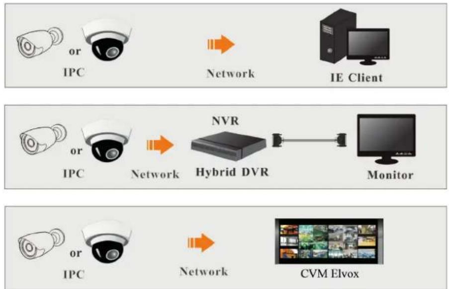
flowchart
graph LR
    A["IPC"] -->|Network| B["IE Client"]
    C["IPC"] -->|Network| D["NVR Hybrid DVR"]
    D --> E["Monitor"]
    F["IPC"] -->|Network| G["CVM Elvox"]
Installation recommended distance (only for fisheye camera):
| Performance Face details | Face contour Human movement | ||
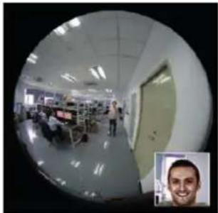 | 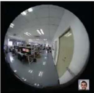 | 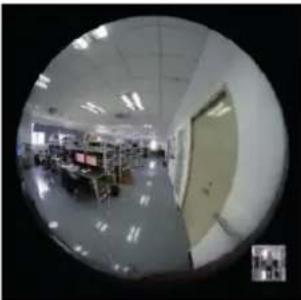 | |
| Object distance 3 m 6 m 12 m | |||
2 - IE Remote Access
You may connect IP-Cam via LAN or WAN. Here only take IE browser (6.0) for example. The details are as follows:
2.1 - LAN
In LAN, there are two ways to access IP-Cam:
1 - access through IP-Tool;
2 - directly access through IE browser.
2.1.1 - Access through IP-Tool
Network connection:
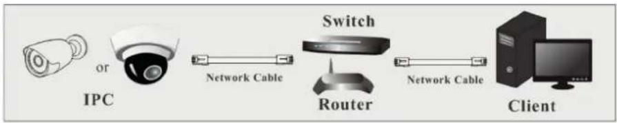
flowchart
graph LR
    A["IPC"] --> B["Switch"]
    B --> C["Client"]
    A --> D["Network Cable"]
    D --> E["Router"]
    E --> F["Network Cable"]
1 - Make sure the PC and IP-Cam are connected to the LAN and the IP-Tool is installed in the PC from the CD.
2 - Double click the IP-Tool icon on the desktop to run this software as shown below:
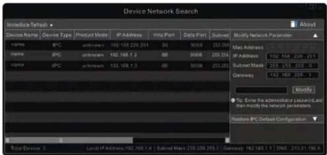
3 - Modify the IP address. The default IP address of this camera is 192.168.226.201. Click the information of the camera listed in the above table to show the network information on the right hand. Modify the IP address and gateway of the camera and make sure its network address is in the same local network segment as the computer's. Please modify the IP address of your device according to the practical situation.
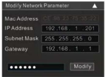
For example, the IP address of your computer is 192.168.1.4. So the IP address of the camera shall be changed to 192.168.1.X. After modification, please input the password of the administrator and click "Modify" button to modify the setting.

The default username is "admin"; the default password is "123456".
Gestione telecamera IP
4 - Double click the IP address and then the system will pop up the IE browser to connect IP-CAM. After you read the privacy statement, check and click "Already Read". Then activate the device.
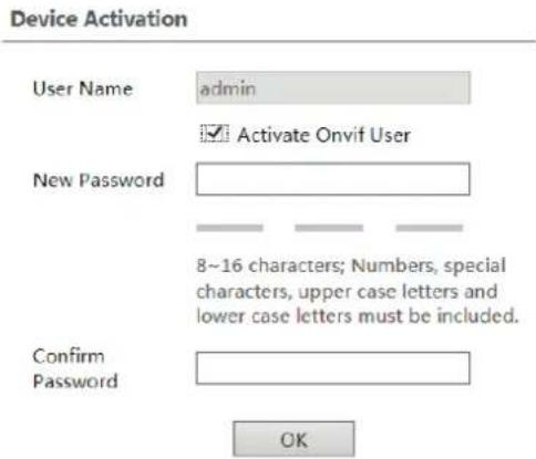
Please self-define the password of admin according to the tip.
If "Activate Onvif User" is enabled, the ONVIF user can be activated simultaneously. When you connect the camera through the ONVIF protocol in the third-party platform, you can use the default username and the password set above to connect. If "Activate Onvif user" is not enabled, the password remains the default "123456"; to modify it, see paragraph 4.5.4.
After that, follow directions to download, install and run the Active X control if prompted. Re-connect your camera via IE browser and then a login box will appear.
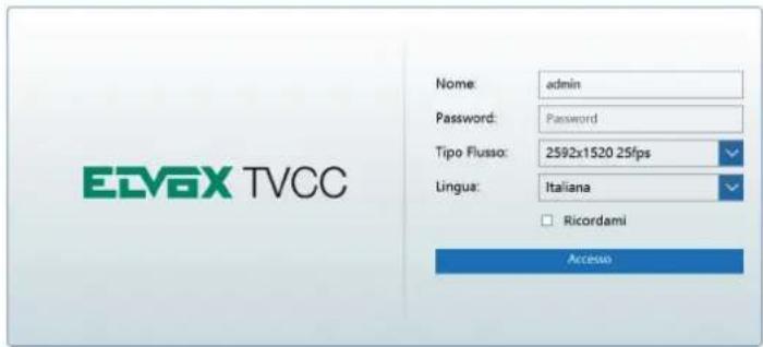
Please enter the user name (admin) and password. Then select the stream type and language as needed. Stream Type: The plug-in free live view only supports1080P or lower resolution.
The security questions should be set after you click "Login" button. It is very important for you to reset your password. Please remember these answers.
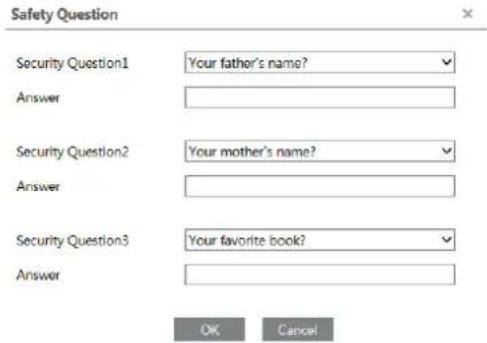
If you forget the admin password, you can reset the password by clicking Forget Password on the login page. Then you can reset the password by the security questions and answers you set.
You can set the account security question during the activation, or you can go to Config → Security User, click Safety Question, select the security questions and input your answers.
IP camera management
2.1.2 - Directly Access through IE
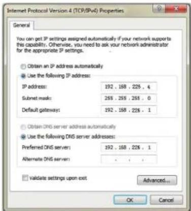
The default network settings are as shown below:
IP address: 192.168.226.201
Subnet Mask: 255.255.255.0
Gateway: 192.168.226.1
HTTP: 80
Data port: 9008
You may use the above default settings when you log in the camera for the first time. You may directly connect the camera to the computer through network cable.

1 - Manually set the IP address of the PC and the network segment should be as the same as the default settings of the IP camera. Open the network and share center. Click "Local Area Connection" to pop up the following window.
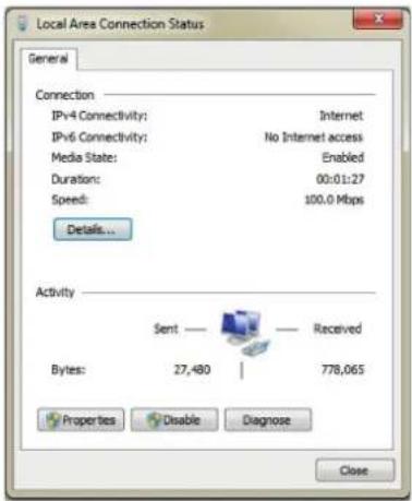
Select "Properties" and then select internet protocol according to the actual situation (for example: IPv4). Next, click "Properties" button to set the network of the PC.
2 - Open the IE browser and input the default address of IP-CAM and confirm. The IE browser will download Active X control automatically.
3 - After downloading Active X control, the login dialog box will pop up.
4 - Input the default username and password and then enter to view.
2.2 - WAN
▶ Access through the router or virtual server

flowchart
graph LR
    A["IPC"] -->|Network Cable| B["Router"]
    B -->|Network Cable| C["Client"]
    C -->|Network Cable| B
IP camera management
1 - Make sure the camera is well connected via LAN and then log in the camera via LAN. Go to Config → Network → Port menu to set the port number.
| HTTP Port | 80 |
| Data Port | 9008 |
| RTSP Port | 554 |
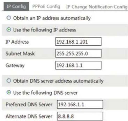
2 - Go to Config - Network TCP/IP menu to modify the IP address.
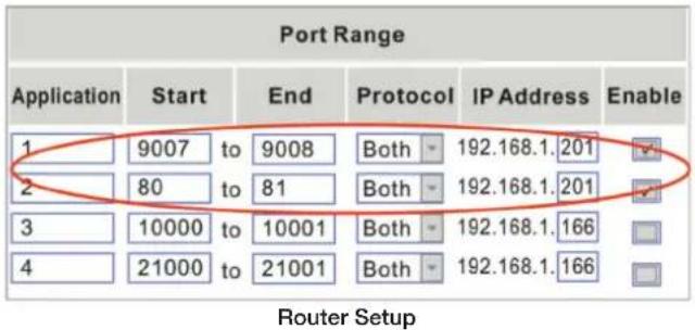
3 - Go to the router's management interface through IE browser to forward the IP address and port of the camera in the "Virtual Server".
4 - Open the IE browser and input its WAN IP and http port to access.
▶ Access through PPPoE dial-up
Network connection

flowchart
graph LR
    A["IPC"] -->|or| B["Modem"]
    B -->|Network Cable| C["Client"]
    B -->|Network Cable| D["Internet"]
    D -->|Network Cable| C
You may access the camera through PPPoE auto dial-up. The setting steps are as follow:
1 - Go to Config - Network Port menu to set the port number.
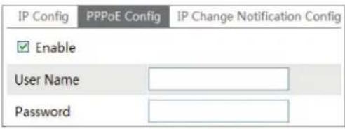
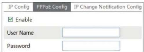
2 - Go to Config → Network → TCP/IPv4 → PPPoE Config menu. Check "Enable" and then input the user name and password which you can get from your internet service provider.
IP camera management
3 - Go to Config → Network → DDNS menu. Before you configure the DDNS, please apply for a domain name first. Please refer to DDNS Configuration for detail information.
4 - Open the IE browser and input the domain name and http port to access.
▶ Access through static IP
Network connection

flowchart
graph LR
    A["IPC"] --> B["Network Cable"]
    B --> C["Internet"]
    C --> D["Network Cable"]
    D --> E["Client"]
The setting steps are as follow:
1 - Go to Config - Network Config Port menu to set the port number.
2 - Go to Config → Network Config → IP Address menu to set the IP address. Check "Use the following IP address" and then input the static IP address and other parameters.
3 - Open the IE browser and input its WAN IP and http port to access.
3 - Remote Preview
3.1 - The Remote Preview Interface
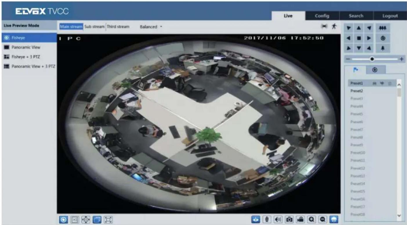
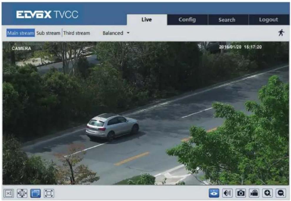
After you log in, you will see the following window.
Only for fisheye camera: before you view the live image, please set the stream mode and installation method as required (see set fisheye parameters for details).
IP camera management
Only for fisheye camera:
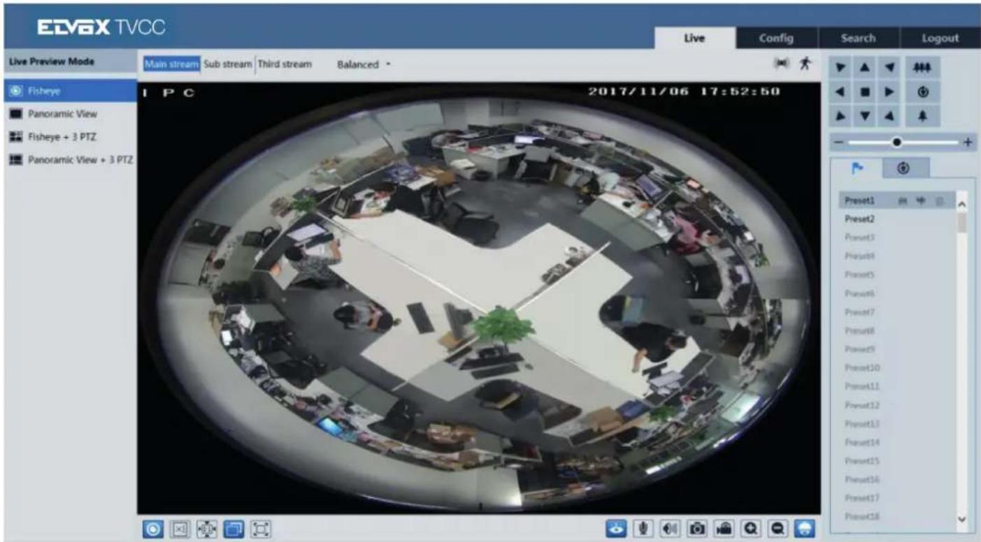
In the live mode, you can switch different streams and live preview modes, capture live images, enable live audio and record, etc. The following table is the instructions of the icons on the remote preview interface.
| Icon Description Icon Description | |||
 | Select live preview mode (only fisheye) Snap |  | |
 | Original size Start/stop recording |  | |
 | Appropriate size PTZ control |  | |
 | Auto Sensor alarm indicator icon |  | |
| [ZYY] | Full screen Motion alarm indicator icon |  | |
 | Start/stop live view Zoom in |  | |
 | Start/stop two-way audio Zoom out |  | |
 | Enable/disable audio | ||
- When motion detection alarm is triggered, the people icon will turn red.
- In full screen mode, double click to exit.
IP camera management

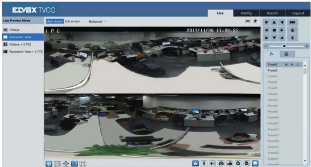
Click to select the live view mode.
Fisheye view mode: see the picture as shown above.
Panoramic view mode
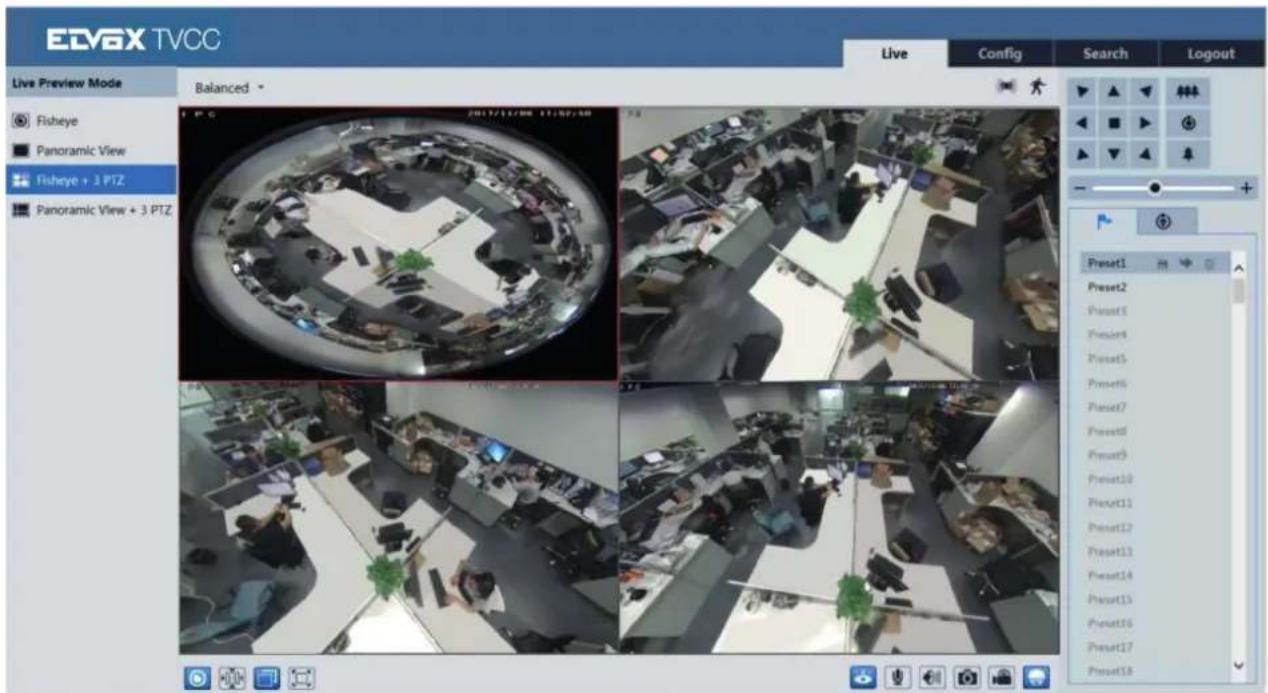
Fisheye + 3 PTZ view mode
IP camera management
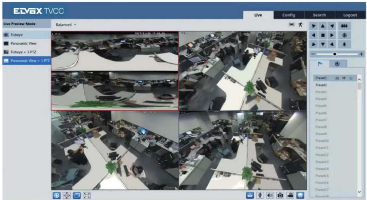
Panoramic + 3 PTZ view mode
4 PTZ view mode (you need to switch the stream mode in the fisheye parameter interface)
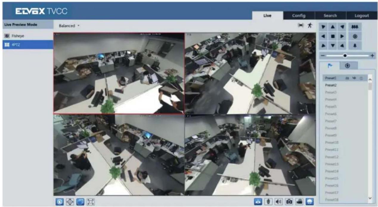
In panoramic + 3 PTZ view mode or fisheye + 3 PTZ view mode or 4 PTZ view mode, select a PTZ window and view the image from every direction by controlling PTZ panel.
IP camera management

Click to unfold the control panel. The descriptions of the control panel are as follows:
| Icon Description Icon Description | |||
 | Click it to rotate the dome diagonally up-left Click it to rotate the dome diagonally up-right | ||
 | Click it to rotate the dome upwards Click it to stop rotating the dome | ||
 | Click it to rotate the dome towards left Click it to rotate the dome towards right | ||
 | Click it to rotate the dome diagonally down-left Click it to rotate the dome diagonally down-right | ||
 | Click it to rotate the dome downwards Drag the scroll bar to adjust rotating speed of the dome | ||
 | Click it to zoom out the live image Click it to zoom in the live image | ||
 | Automatic cruise Preset | ||
 | Create and call cruise | ||
Select preset and click → to call the preset. Select and set the preset and then click to save the position of the preset. Select the set preset and click → to delete it. Select cruise and click → to set the cruise and add presets to this cruise. Click → to start cruise; click → to stop cruise.
4 - Remote Live Surveillance
4.1 - System Configuration
The "System Configuration" includes three submenus: Basic Information, Date & Time and Local Configuration.
4.1.1 - Basic Information
In the Basic Information interface, you can check the relative information of the device.
| Device Type | xxxx |
| Brand | xxxx |
| Software Version | 4.0.2.0 |
| Software Build Date | 2016-01-14 |
| Kernel Version | 20160109 |
| Hardware Version | 1.3 |
| Onvif Version | 2.3 |
| OCX Version | 1.0.6.7 |
| MAC | 00:94:34:43:0f:69 |
4.1.2 - Date & Time
Go to Config -System Date and Time. Please refer to the following interface.

You can select the time zone and DST as required.
Click "Date and Time" to set the time mode.
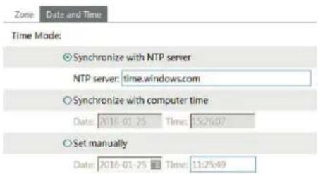
IP camera management
4.1.3 - Local Configuration
Go to Config → System -Local Config. You can set the storage path of the captured pictures and video records.
| Picture Path | D:\Favorites | Browse | |
| Record Path | D:\Favorites | Browse | |
| Video Sound Settings | ○ Open | ● Close | |
4.1.4 - Storage
Go to Config - System Storage to go to the interface as shown below.
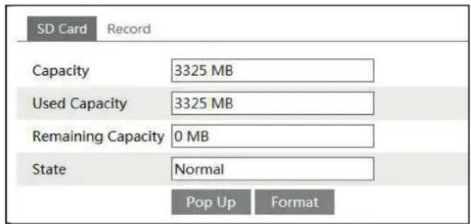
The first time you use the SD card, you should click "Format", button to format the SD card. Click "Pop up" button to stop writing data to SD card. Then the SD card can be ejected safely.
Note: using of SD card function should be coordinated with motion or sensor alarm. When alarm is triggered, the system will automatically capture picture and save the picture or record into SD card.
Go to Config → System → Record to go to the interface as shown below. You can set the SD card record stream. Set the pre record time if you enable pre record. Click "Save" button to save the settings.
Pre record time: Set the time to record before the actual recording begins.
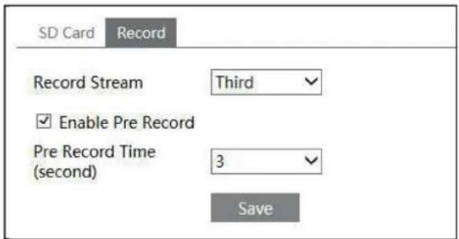
4.1.5 - Set fisheye parameters
Before viewing the live image, please go to Config → System -Fisheye parameters menu to set the stream mode and installation method.
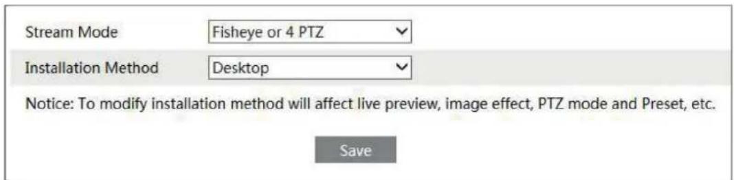
Stream mode: Fisheye + Panoramic view + 3 PTZ & Fisheye or 4 PTZ mode are optional. Installation method: Wall, ceiling and desktop are optional. Please select the installation mode according to the actual installation method.
IP camera management
4.2 - Image Configuration
Image Configuration includes five submenus: Display, Video/Audio, OSD, Video Mask and ROI Config.
4.2.1 - Display Configuration
Many parameters of the camera can be set in display configuration interface such as brightness, contrast, chroma, saturation wide dynamic, etc.
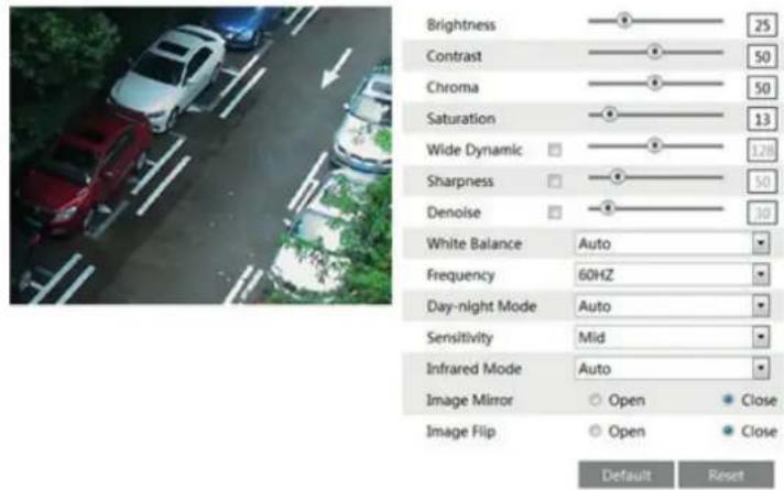
Only for fisheye camera:
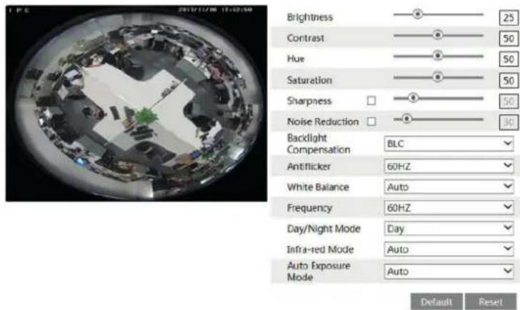
Brightness: set the brightness level of the camera's image.
Contrast: set the color difference between the brightest and darkest parts.
Hue: set the total color degree of the image.
Saturation: set the degree of color purity. The purer the color is, the brighter the image is.
Sharpness: set the resolution level of the image plane and the sharpness level of the image edge.
Noise Reduction: decrease the noise and make the image more thorough. Increasing the value will make the noise reduction effect better but it will reduce the image resolution.
Backlight Compensation:
- Off: close the backlight compensation function. It is the default mode.
- HWDR
As to the WDR scene, WDR will help the camera provide clear images when there are both very bright and very dark areas simultaneously in the field of the view by lowering the brightness of the highlight area and increasing the brightness of the lowlight area. High, middle and low can be selected.
There will be some record lost in a few seconds during mode changing from non-WDR to WDR mode.
- HLC: lower the brightness of the whole image by suppressing the brightness of the image's highlight area and reducing the size of the halo area.
- BLC: if enabled, the auto exposure will activate according to the scene so that the object of the image in the darkest area will be seen clearly.
Antiflicker:
- Off: close the anti-flicker function.
- 50Hz: make sure the horizontal stripes will not appear in the image while the device is adjusting the exposure automatically according to the brightness of the scene.
- 60Hz: make sure the horizontal stripes will not appear in the image while the device is adjusting the exposure automatically according to the brightness of the scene.
White Balance: adjust the color temperature according to the environment automatically.
Frequency: 50Hz and 60Hz can be optional.
Day/night Mode: please choose the mode as needed.
Sensitivity: high, middle and low can be selected.
Infrared Mode: you may choose "ON", "OFF" and "Auto" as required.
Exposure Mode: you may choose "Auto" or "Manual" as required.
4.2.2 - Video Stream
The following interface will be displayed by clicking Config -Image Video/Audio.
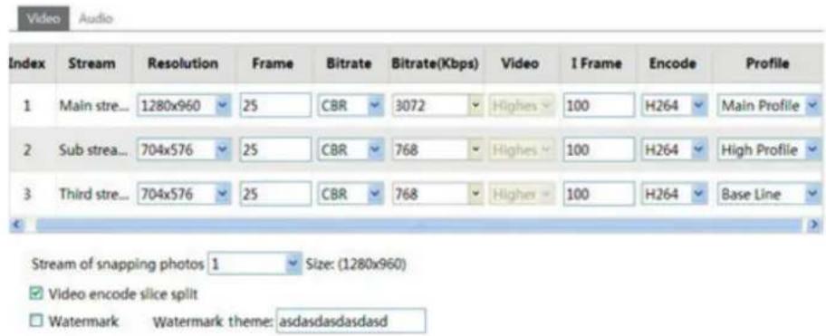
In this interface, you can set the resolution, frame rate, bitrate type, video quality and so on subject to the actual network condition.
To set the audio encoding and audio type, please select the audio tab.

Only for fisheye camera:
- IP Channel 1: Fisheye view channel, 3 streams can be set. Please set them according to the actual network condition.
- IP Channel 2: Panoramic view channel, 2 streams can be set. Please set them according to the actual network condition.
- IP Channel 3/4/5: PTZ view channel, 2 streams can be set for each channel. Please set them according to the actual network condition.
Three video streams can be adjustable.
Resolution: The higher the resolution is, the clearer the image is.
Frame rate: The higher the frame rate is, the more fluency the video is. However, more storage room will be taken up.
Bitrate type: Including CBR and VBR. CBR means that no matter how changeable the video resources are, the compression bitrate keeps constant. This will not only facilitate the image quality better in a constant bitrate but also help to calculate the capacity of the recording. VBR means that the compression bitrate can be adjustable according to the change of the video resources. This will help to optimize the network bandwidth.
Video Quality: When VBR is selected, you need to choose image quality. The higher the image quality you choose, the more bitrate will be required.
Bitrate: Please choose it according to the actual network situation.
I Frame interval: It is recommended to use the default value. If the value is over high, the read speed of the group of pictures will be slow resulting in the quality loss of the video.
Video encoding profile: Baseline and main profile are optional. Baseline profile is mainly used in interactive application with low complexity and delay. Main profile is mainly used for higher coding requirement.
Sending Snapshot: Please select it according to the actual situation.
Video encode slice split: If enabled, you may get more fluency image even though using the low-performance PC.
Watermark: If selected, you can input the watermark theme. You may check the watermark when playing back the local record in the search interface, lest the record files is tampered.
Audio Encoding: G.711A and G.711U are selectable.
Audio In Type: MIC and LIN are selectable.
4.2.3 - OSD Configuration
Go to Config -Image OSD menu to display the interface as shown below:
natural_image
A car driving on a tree-lined road with green foliage in the background (no visible text or symbols)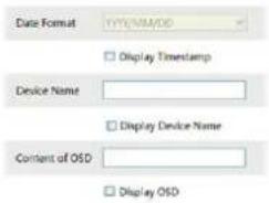
Only for fisheye camera:
natural_image
Fisheye lens image showing a central green object surrounded by mechanical components (no visible text or symbols)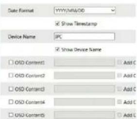
You may set time stamp, device name and OSD here. After enabling the corresponding display and entering the content, drag them to change their position.
Then press the "Save" button to save the settings.
IP camera management
4.2.4 - Video Mask
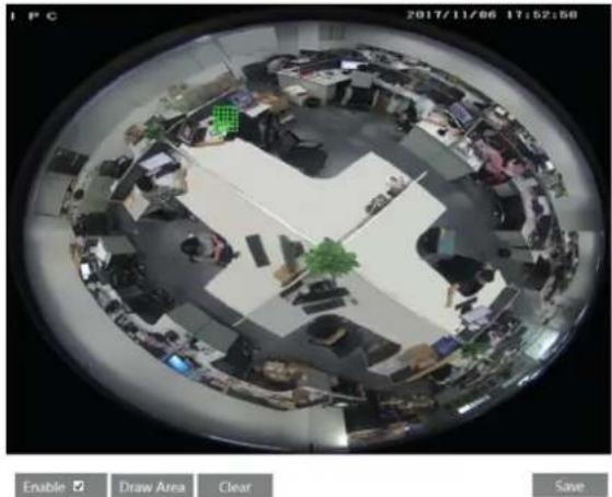
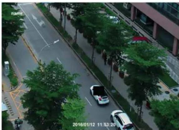
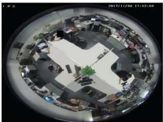
Go to Config → Image -Video Mask menu to display the interface as shown below. You can set 4 mask areas at most.
Only for fisheye camera:
natural_image
Fisheye view of a circular office interior with multiple workstations and central plants (no visible text or symbols)To set up video mask
1 - Open video mask.
2 - Click "Draw Area" button and then drag the mouse to draw the video mask area.
3 - Click "Save" button to save the settings.
4 - Return to the live to see the following picture.
Only for fisheye camera:
natural_image
Overhead fisheye view of a busy office workspace with multiple workstations and employees (no visible text or symbols)Clear the video mask:
Go to video mask menu and then click "Clear" button to delete the current video mask area.
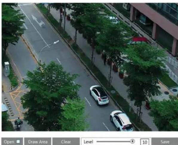
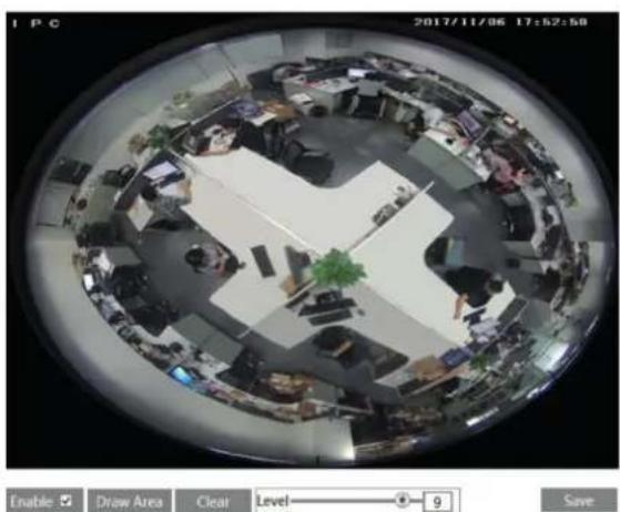
4.2.5 - ROI Configuration
To set up ROI
1 - Go to Video Config → Config menu.
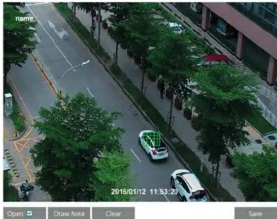
natural_image
Aerial view of a city street with cars and trees, no visible text or symbolsOnly for fisheye camera:
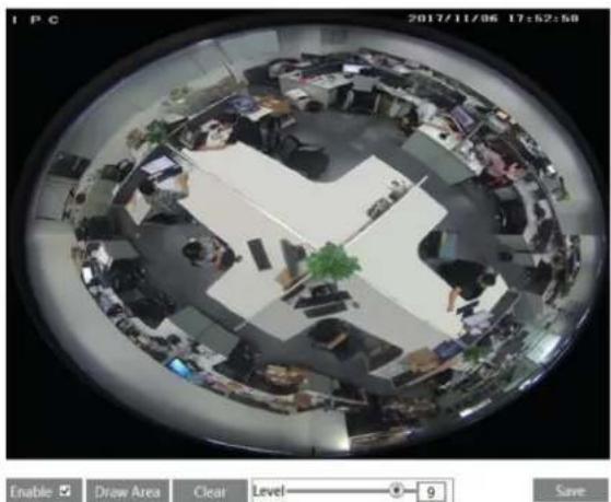
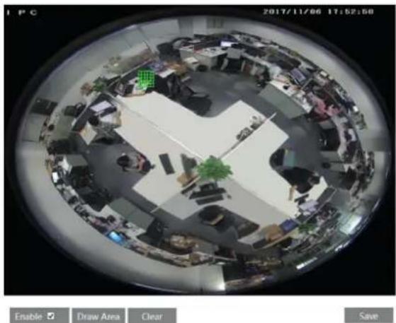
natural_image
Fisheye view of an office interior with cubicles and desks, no visible text or symbolsIP camera management
2 - Check "Open" and then click "Draw Area" button.
3 - Drag the mouse to set the ROI area.
4 - Set the level.
5 - Click "Save" button to save the settings.
Now, you will see the selected ROI area is detailed than other areas especially in low bitrate condition.
4.3 - PTZ Configuration (Fisheye)
The PTZ of this camera can be controlled by the keyboard. Connect the keyboard and the camera through RS485 interface and then set the corresponding protocol and baud-rate in the camera and keyboard. Go to PTZ → Protocol interface as shown below.
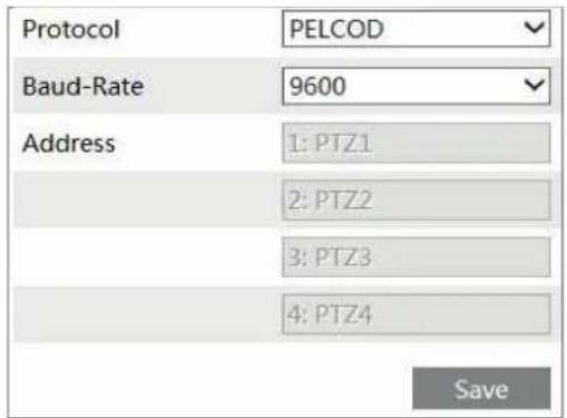
Here the protocol and baud-rate must be the same with these of the keyboard.
Address: 1; you can control PTZ channel 1 by using this address in the keyboard.
Address: 2; you can control PTZ channel 2 by using this address in the keyboard.
......
4.4 - Alarm Configuration
Alarm configuration includes four submenus: Motion Detection, Alarm In, Alarm Out and Alarm Server.
4.4.1 - Motion Detection
To set motion detection:
1 - Go to Config - Alarm Motion Detection to set motion detection alarm.
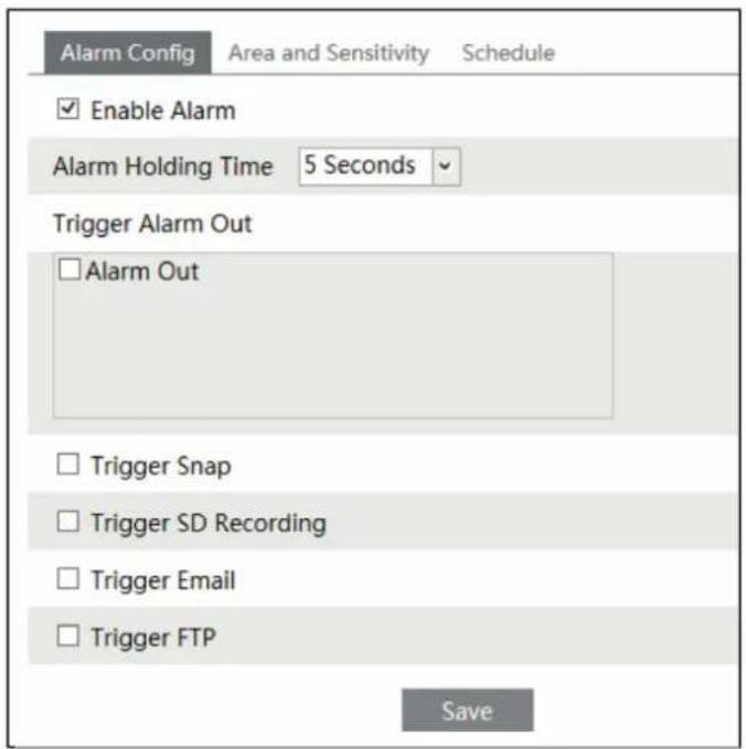
Check "Enable Alarm" check box to activate motion based alarm, choose alarm holding time and set alarm trigger options.
Alarm Out: If selected, this would trigger the external relay output on detecting a motion based alarm.
Trigger Snap: If selected, the system will capture images on an alarm and save the images in SD card.
Trigger SD Recording: If selected, the record will be triggered and saved in SD card on an alarm.
Check "Enable Alarm" check box to activate motion based alarm, choose alarm holding time and set alarm trigger options.
Trigger Email: If the email and attach picture checkbox is checked (Email address shall be set first in the Mail config interface), the triggered snap pictures and event will be sent into those addresses.
Trigger FTP: If "Uploading picture" is checked, the triggered snap pictures will be sent into FTP server address. Please refer to FTP configuration chapter for more details.
IP camera management
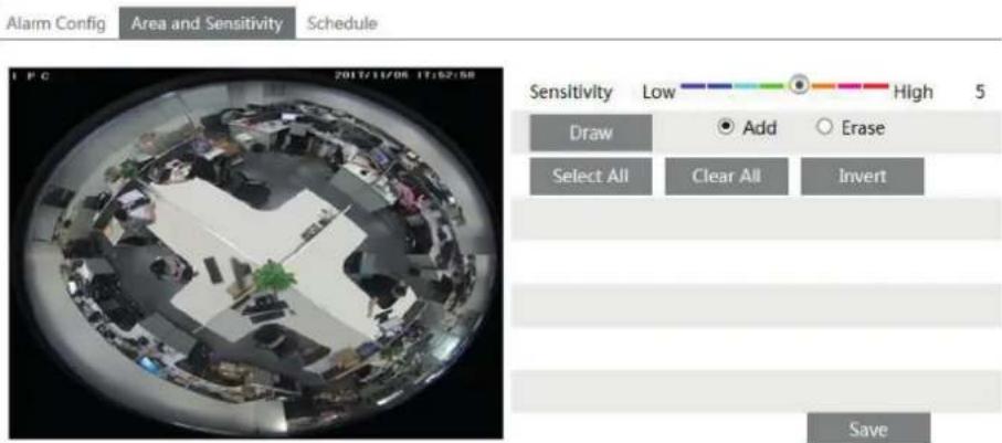
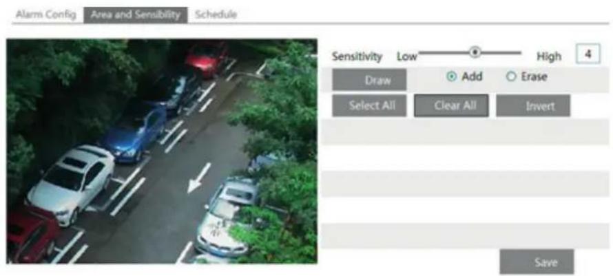
2 - Set motion detection area and sensitivity. Click "Area and Sensitivity" tab to see the following sub-menu.
Only for fisheye camera:
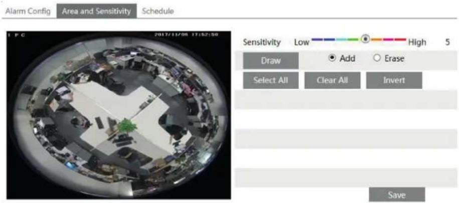
Move the "Sensitivity" scroll bar to set the sensitivity.
Check "Add" and click "Draw" button and move mouse to select the motion detection area; Select "Erase" and move the mouse to clear motion detection area. After that, click "Save" to save the settings.
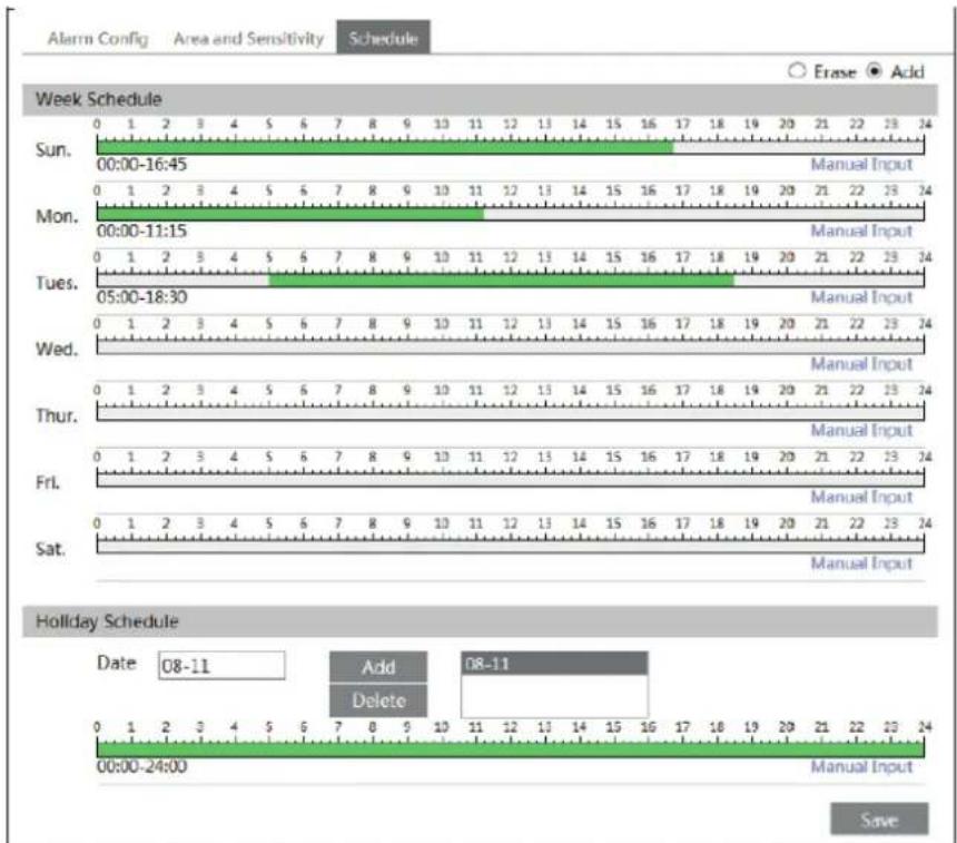
3 - Set the schedule of the motion detection. Click "Schedule" tab to set the schedule of the motion detection.
IP camera management
Week schedule
Set the alarm time from Monday to Sunday for alarm everyday in one week. The lengthwise means one day of a week; the rank means 24 hours of a day. Green means selected area. Blank means unselected area.
"Add": Add the schedule for a special day.
"Erase": Delete holiday schedule.
Day schedule
Set alarm time for alarm in some time of a special day, such as holiday.
Select a date at the "Date" pull down list, press "Add" button to add that date to the list box on the right side and then move the scroll bar to set the schedule of that day.
Select a date in the list box on the right side, and press "Delete" to remove the schedule on that day.
Press the "Save" button to save the settings.
Note: Holiday schedule is prior to Week schedule.
4.4.2 - SD Card Full
1 - Go to Config → Alarm Exception SD Card Full.
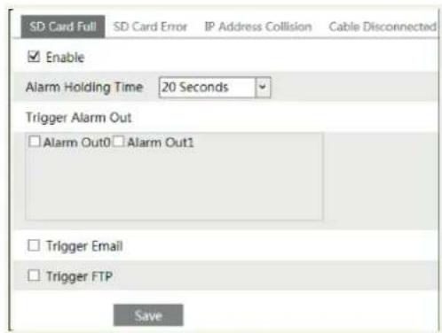
2 - Click "Enable" and set the alarm holding time.
3 - Set alarm trigger options. The setup steps are the same astemperature measurement settings.
Please refer to temperature measurement settings chapter for details.
4.4.3 - SD Card Error
When there are some errors in writing to the SD card, the corresponding alarms will be triggered.
- Go to Config → Alarm -Exception SD Card Error as shown below.
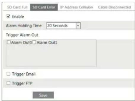
2 - Click "Enable" and set the alarm holding time.
3 - Set alarm trigger options. Trigger alarm out, Email and FTP. The setup steps are the same astemperature measurement settings. Please refer to temperature measurement settings chapter for details.
IP camera management
4.4.4 - IP Address Conflict
- Go to Config → Alarm Exception IP Address Collision as shown below.
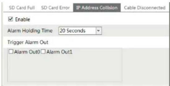
- Click "Enable alarm" and set the alarm holding time.
- Trigger alarm out. When the IP address of the camera is in conflict with the IP address of other devices, the system will trigger the alarm out.
4.4.5 - Cable Disconnection
- Go to Config → Alarm -Exception Cable-Disconnected as shown below.
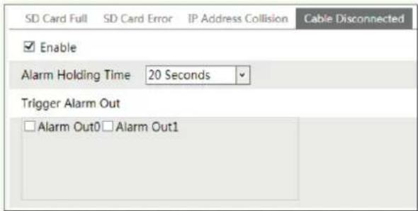
- Click "Enable" and set the alarm holding time.
- Trigger alarm out. When the camera is disconnected, the system will trigger the alarm out.
4.4.6 - Alarm In
To set sensor alarm (alarm in):
Go to Config -Alarm Alarm In interface as shown below.
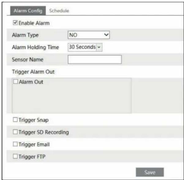
1 - Enable alarm and set the alarm type, alarm holding time and sensor name.
2 - Set alarm trigger options. The setting steps are the same with that of motion detection. Please refer to motion detection chapter for details.
3 - Click "Save" button to save the settings.
4 - Set the schedule of the sensor alarm. The setting steps of the schedule are the same with that of motion detection. Please refer to motion detection chapter for details.
IP camera management
4.4.7 Alarm Out
This function is only available for some models. Go to Config → Alarm -Alarm Out.
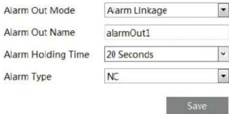
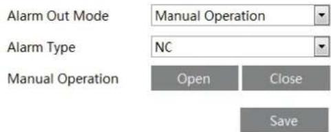
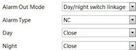
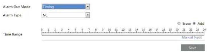
Alarm Out Mode: Alarm linkage, manual operation, day/night switch linkage and timing are optional.
Alarm Linkage: Having selected this mode, select alarm out name, alarm holding time at the "Alarm Holding Time" pull down list box and alarm type.
Manual Operation: Having selected this mode, select the alarm type and click "Open" to trigger the alarm out immediately; click "Close" to stop alarm.
Day/Night Switch Linkage: Having selected this mode, select the alarm type and then choose to open or close alarm out when the camera switches to day mode or night mode.
Timing: Select the alarm type. Then click "Add" and drag the mouse on the timeline to set the schedule of alarm out; click "Erase" and drag the mouse on the timeline to erase the set time schedule. After this schedule is saved, the alarm out will be triggered in the specified time.
4.4.8 - Alarm Server
Go to "Alarm configuration" — "Alarm Server" interface as shown below.
You may input the alarm server address and port. When the alarm happens, the camera will automatically transfer the alarm event to the alarm server. If the alarm server is not used, there is no need for you to configure here.

4.4.9 Audio Alarm
Go to Alarm -Audio Alarm interface as shown below.
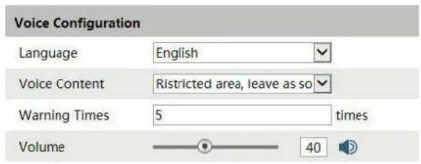
OK
- Select the language. If you want to customize the voice content, you can choose "Customize". Click "Browse" to choose the audio file you want to upload and then enter the audio name. Finally, click "Upload" to upload the audio file. Note that the format of the audio file must meet the requirement (see Tips), or it will not be uploaded. After you upload the audio file, you can select the audio name from the audio list and click "Listen" to listen to it. Click "Delete" to delete the audio.
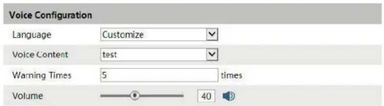
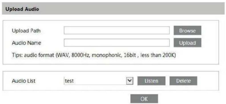
-
Select the voice content and then set the warning times and volume as needed. Warning times: it ranges from 1 to 50.
-
Click "OK" to save the settings.
4.4.10 Light Alarm
Go to Alarm - Light Alarm interface as shown below. Set the flashing time and frequency of the light.
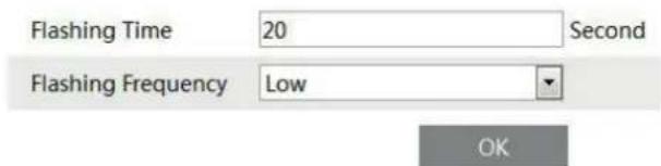
Flashing time: the flashing time ranges from 1 second to 60 seconds. Flashing Frequency: three options- low, middle and high
4.5 - Network Configuration
4.5.1 - TCP/IPv4
Go to Config Network TCP/IP4. There are two ways for network connection.
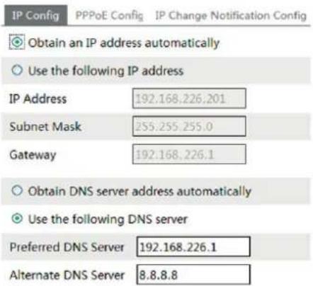
- Use IP address. There are two options for IP setup: obtain an IP address auto by DHCP protocol and use the following IP address. Please choose one of options for your requirements.
- Use PPPoE: Enter the user name and password from your ISP.
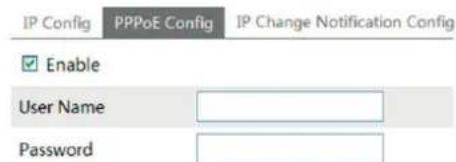
You can choose either way of the network connection. If you use PPPoE to connect internet, you will get a dynamic WAN IP address. This IP address will change frequently. You may use the function of IP change notification.
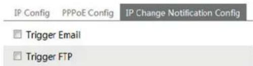
Trigger Email: when the IP address of the device is changed, a new IP address will be sent to the appointed mailbox automatically. Trigger FTP: when the IP address of the device is changed, a new IP address will be sent to FTP server.
4.5.2 - Port
Go to Config - Network Port. HTTP port, Data port and RTSP port can be set.
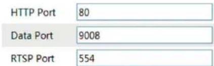
HTTP Port: The default HTTP port is 80. It can be changed to any port which is not occupied. Data Port: The default data port is 9008. Please change it as required. RTSP Port: The default port is 554. Please change it as required.
4.5.3 - Central Server
This function is mainly used for connecting network video management system.
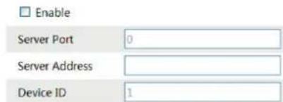
1 - Check "Enable".
2 - Check the IP address and port of the transfer media server in the CVM ELVOX. Then enable the auto report in the CVM ELVOX when adding a new device in the CVM ELVOX. Next, input the remaining information of the device. After that, the system will auto allot a device ID. Please check it in the CVM ELVOX.
3. Input the above-mentioned server address, server port and device ID in the responding boxes. Click "Save" button to save the settings.
IP camera management
4.5.4 - Onvif
The camera can be searched and connected to the third-party platform via ONVIF/RTSP protocol.
If "Activate Onvif User" is enabled in the device activation interface, the ONVIF user can be activated simultaneously. When you connect the camera through the ONVIF protocol in the third-party platform, you can use this onvif user to connect.
You can also add new users in the Onvif interface.
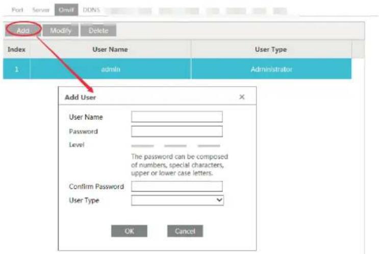
Note: when adding the device to the third-party platform with ONVIF/RTSP protocol, please use the onvif user in the above interface.
4.5.5 - DDNS Configuration
If your camera is set to use PPPoE as its default network connection, DDNS should be set for network access. Before you set the DDNS, please make sure you have registered a domain name on the DDNS server.
1 - Go to Config → Network -DBNS
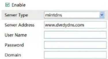
2 - Apply for a domain name. Take www.dvrdyndns.com for example. Input www.dvrdydns.com in the IE address bar to visit its website. Then click "Registration" button
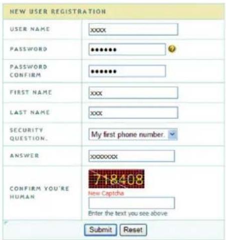
Create domain name
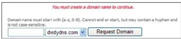
After you successfully request your domain name, you will see your domain in the list.
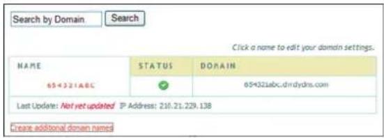
3 - Input the username, password, domain you apply for in the DDNS configuration interface.
4 - Click "Save" button to save the settings.
4.5.6 - SNMP
To get camera status, parameters and alarm information and remotely manage the camera, you can set the SNMP function. Before using the SNMP, please download the SNMP software and set the parameters of the SNMP, such as SNMP port, trap address.
1 - Go to Config → Network -SNMP.
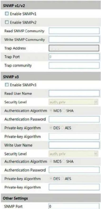
2 - Check the corresponding version checkbox (Enable SNMPv1, Enable SNMPv2, Enable SNMPv3) according to the version of the SNMP software you download.
3 - Set the "Read SNMP Community", "Write SNMP Community", "Trap Address", "Trap Port" and so on. Please make sure the settings are the same as that of your SNMP software.
Note: Please use the different version in accordance with the security level you required. The higher the version is, the higher the level of the security is.
IP camera management
4.5.7 - 802.1x
If it is enabled, the camera's data can be protected. When the camera is connected to the network protected by the IEE802.1x, user authentication is needed.
| Enable | |
| Protocol Type | EAP_MD5 |
| EAPOL Version | 1 |
| User Name | test |
| Password | ●●●●●● |
| Confirm Password | ●●●●●● |
To use this function, the camera shall be connected to a switch supporting 802.1x protocol.
The switch can be reckoned as an authentication system to identify the device in a local network. If the camera connected to the network interface of the switch has passed the authentication of the switch, it can be accessed via the local network.
Protocol type and EAPOL version: Please use the default settings.
User name and password: The user name and password must be the same with the user name and password applied for and registered in the authentication server.
4.5.8 - RTSP
Go to Config Network RTSP.
Enable
| Port | 554 |
| Address | rtsp://IP or domain name:port/profile1 |
| rtsp://IP or domain name:port/profile2 | |
| rtsp://IP or domain name:port/profile3 |
□ Allow anonymous viewer login (No user name or password required)
1 - Select "Enable".
2 - RTSP Port: Access port of the streaming media. The default number is 554.
3 - RTSP Address: The RTSP address you need to input in the media player.
4 - Check "Enable anonymous viewer login...".
4.5.9 - UPNP
If you enable this function, you can quickly access the camera via LAN and you don't need to configure the port mapping when the camera is connected to the WAN via the router.
Go to Config Network UPnP:
Select "Enable UPNP" and then input friendly name.
Enable
UPnP Name
After you enable it and set the UPnP name, you will see the UPnP name by clicking "Network" on the desktop of your computer which is in the same local area network. Then double click this name to access the camera quickly.
IP camera management
4.5.10 - Mail configuration
If you need to trigger E-mail when an alarm happens or IP address is changed, please set the E-mail here first. Go to Config → Network -Email.
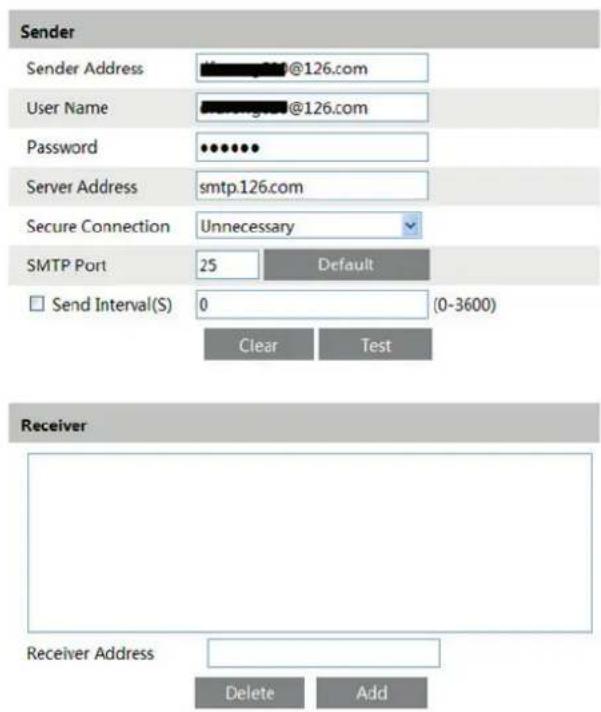
Sender Address: sender's e-mail address;
User name and password: sender's user name and password;
SMTP Address: The SMTP IP address or host name.
Select the secure connection type at the Secure Connection pull down list according to user' actual needs;
SMTP Port: The SMTP port.
Send Intervals: Set it as needed.
Click "Test Account Setting" to test the effectiveness of the account.
Receiver email address: receiver's e-mail address;
4.5.11 - FTP Setting
After you set the FTP server, the captured pictures on an alarm will be uploaded to the FTP server.
Go to Config Network FTP.
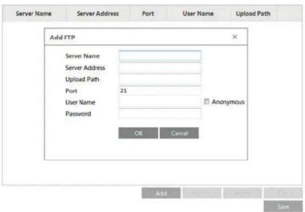
To Add FTP
Server Name: The name of the FTP.
Server Address: The IP address or domain name of the FTP.
Upload Path: The path of uploading the files.
Port: The port of the FTP.
Use Name and Password: The username and password are used to login the FTP.
4.5.12 - HTTPS
HTTPS provides authentication of the web site and protects user privacy. Go to Config → Network HTTPS as shown below.
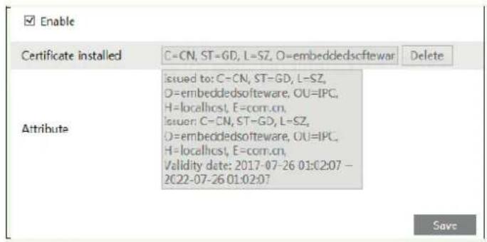
There is a certificate installed by default as shown above. Enable this function and save it.
Then the device can be accessed by entering https://IP: https port via the web browser (eg. https://192.168.226.201:443).
A private certificate can be created if users don't want to use the default one. Click "Delete" to cancel the default certificate. Then the following interface will be displayed.
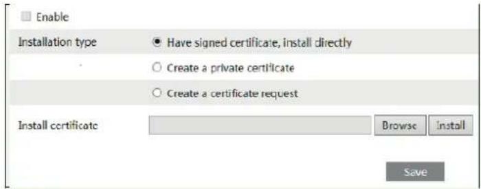
* If there is a signed certificate, click "Browse" to select it and then click "Install" to install it.
* Click "Create a private certificate" to enter the following creation interface.
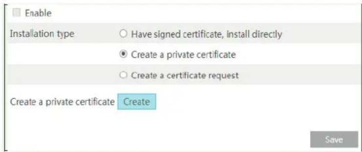
Click the "Create" button to create a private certificate. Enter the country (only two letters available), domain (camera's IP address/domain), validity date, password, province/state, region and so on. Then click "OK" to save the settings.
* Click "Create a certificate request" to enter the following interface.
IP camera management
4.5.13 - QoS
QoS (Quality of Service) function is used to provide different quality of services for different network applications. With the deficient bandwidth, the router or switch will sort the data streams and transfer them according to their priority to solve the network delay and network congestion by using this function.
Go to Config → Network -QoS.
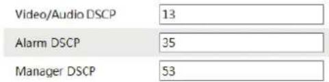
Video/Audio DSCP: The range is from 0 to 63.
Alarm DSCP: The range is from 0 to 63.
Manager DSCP: The range is from 0 to 63.
Generally speaking, the larger the number is, the higher the priority is.
4.6 - Security Configuration
4.6.1 - User Configuration
Go to Config → Security.
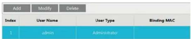
Add user:
1 - Click "Add" button to pop up the following textbox.
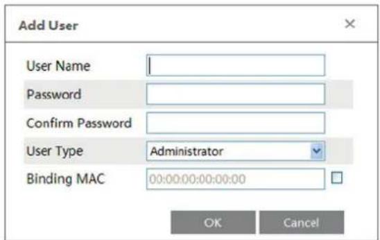
2 - Input user name in "User Name" textbox.
3 - Input letters or numbers in "Password" and "Confirm Password" textbox.
4 - Choose the use type.
5 - Input the MAC address of the PC in "Binding MAC address" textbox.
After binding physical address to the IP-CAM, you can access the device on this PC only. If the MAC address was "00:00:00:00:00:00" which means it can be connected to any computers.
6 - Click "OK" button and then the new added user will display in the user list.
Modify user:
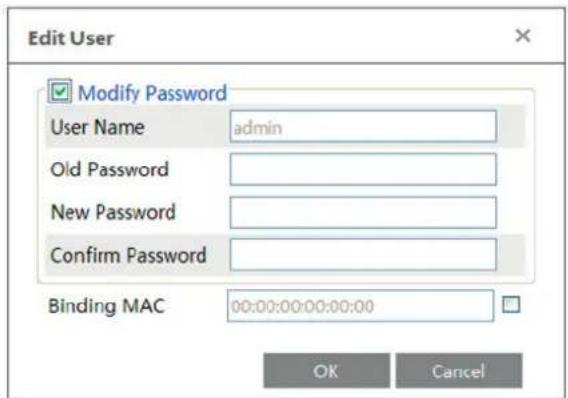
1 - Select the user you need to modify password and physical address in the user configuration list box.
2 - The "Edit user" dialog box pops up by clicking "Modify" button.
IP camera management
3 - Input old password of this user in the "Password" text box.
4 - Input new password in the "New password" and "Confirm Password" text box.
5 - Input computer's MAC address as required.
6 - Click "OK" button to modify user's password.
Delete user:
1 - Select the user you want to delete in the user configuration list box.
2 - Click "Delete" button to delete the user.
Note: The default super administrator cannot be deleted.
4.6.2 - Online Video User
Go to Config → Security – Online Video User. You can view the user who is viewing the live video.
4.6.3 - Block and Allow List
Go to Config → Security Block and Allow Lists.
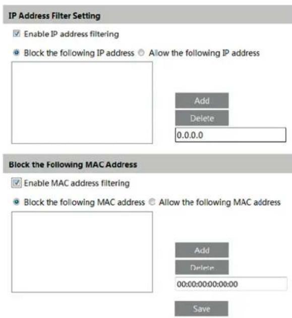
Setting steps are as follows:
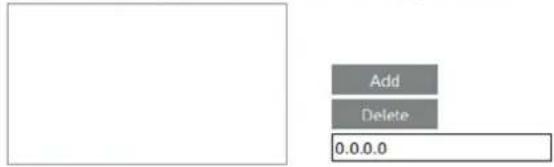
Check "Enable IP address filtering" check box.
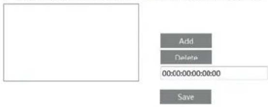
Select "Block the following IP address", input IP address in the IP address list box and click "Add" button. The operation step of "Allow the following IP address" and MAC address filter settings are the same with "Block the following IP address".
After you set the IP address or MAC address, the system will block or allow the user using the added IP address or MAC address to access the camera.
4.6.4 - Security Management
Go to Config → Security - Security Management as shown below.
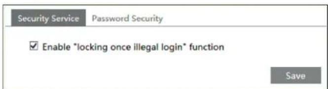
In order to prevent against malicious password unlocking, "locking once illegal login" function can be enabled here. If this function is enabled, login failure after trying six times will make the login interface locked. The camera can be logged in again after a half hour or after the camera reboots.
4.7 - Maintenance
Go to Config → Maintenance - Backup & Restore.
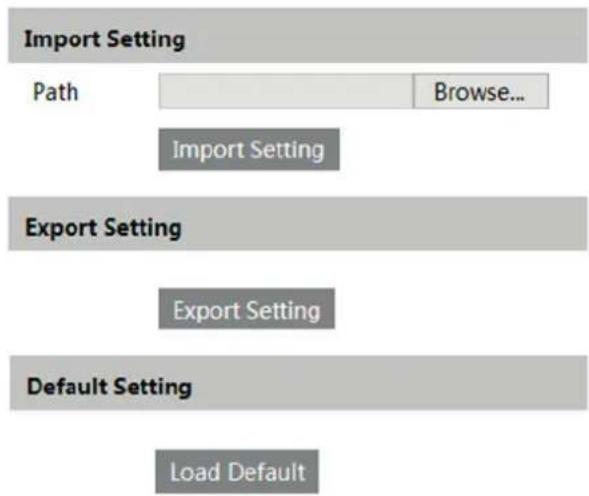
flowchart
graph TD
    A["Import Setting"] --> B["Path"]
    B --> C["Import Setting"]
    D["Export Setting"] --> E["Export Setting"]
    F["Default Setting"] --> G["Load Default"]
- Import & Export Setting:
You can import or export the setting information from PC or to device.
1 - Click "Browse" to select save path for import or export information on PC.
2 - Click "Import Setting" or "Export Setting" button.
- Default Setting
Click "Load default" button to restore all system settings to default status.
4.7.2 - Reboot Device
Go to Config - Maintenance Reboot
Click "Reboot" button to reboot the device.
4.7.3 - Upgrade
Go to Config - Maintenance Upgrade. In this interface, you can upgrade the system.
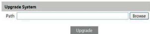
1 - Click "Browse" button to select the save path of the upgrade file
2 - Click "Upgrade" button to start upgrading the application program.
3 - The device will restart automatically
4 - After you successfully update the software, click "OK" button to close IE and then re-open IE to connect IP-Cam.
Caution! You can't disconnect to PC or close the IP-CAM during upgrade.
4.7.4 - Log
To query and export log
1 - Go to Config - Maintenance Operation Log.
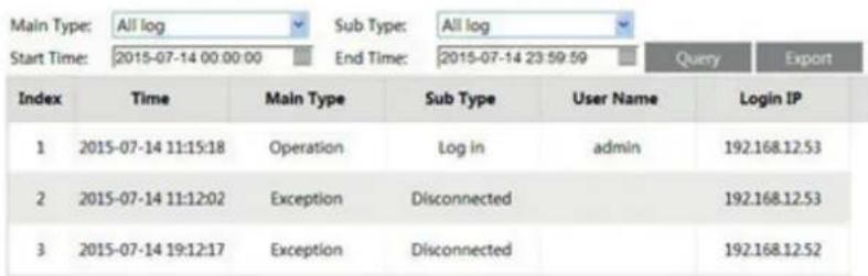
2 - Select the main type, sub type, start and end time.
3 - Click "Query" to view the operation log.
4 - Click "Export" to export the operation log.
You can export and view the run log by clicking Config -Maintenance Run-Log.
4.8 - Temperature Measurement (for thermal cameras only)
Temperature Measurement: When a temperature of the pre-defined point/line/area exceeds the temperature threshold value, alarms will be triggered. Click Config → Temperature measurement to enter the following interface.
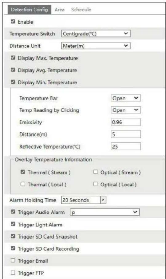
- Click "Enable" and set the temperature measurement parameters.
Temperature Switch: select the temperature unit (°C or °F).
Distance Unit: set the unit of the temperature measurement distance. "Meter" or "Foot" can be selected.
Display Max. Temperature: if checked, the Max. Temperature in the set area/line will be displayed in real time.
Display Avg. Temperature: if checked, the Avg. Temperature in the set point/area/line will be displayed in real time.
Display Min. Temperature: if checked, the Min. Temperature in the set area/line will be displayed in real time.
Temperature Bar: if "Open" is selected, a color reference temperature bar will appear on the right of the thermal image in the live view interface as shown below.
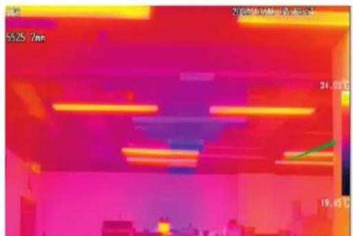
The current minimum and maximum temperature of the scene will display. The minimum temperature shows at the bottom of the bar; the maximum temperature shows on the top of the bar.
Enable Temp Reading by Clicking: if checked, you can read the real-time temperature of any point you click on the thermal image in the live interface. Emissivity: Set the emissivity of the target. The emissivity of each object is different. Please refer to Common Material Emissivity for details.
Distance: The distance between the target and the camera.
Reflective: If there is any object with high emissivity in the scene, set the reflective temperature to correct the ambient temperature. The reflective temperature should be set the same as the temperature of the high emissivity object.
Gestione telecamera IP
Overlay temperature information:
Thermal/optical (local): if enabled, the temperature information shown in the live view interface will get locally. However, when playing back the recorded files, the temperature information will not be overlaid.
Thermal/optical (stream): if enabled, the temperature information will overlay on the video stream. When playing the live video or the recorded video, you can view the temperature information.
Note:
a. for some models, if "Optical (stream)" is enabled, the max. resolution of the main stream is 1080P; the temperature information can be overlaid on the third stream but cannot be overlaid on the sub stream.
b. for some models, overlaying temperature on optical image and dual image fusion cannot be enabled simultaneously.
c. for some models, "thermal (stream) and/or optical (stream)" and "OSD Content3" cannot be enabled simultaneously.
d. for some models, "temperature bar" and "OSD Content3" cannot be enabled simultaneously.
-
Set the alarm holding time and alarm trigger options. The setup steps are the same as fire detection. Please refer to Fire Detection section for details.
-
Set thermography rule. Click the "Area" tab to go to the following interface. The thermography rule type includes Point, Line and Area.
Point setting: After the type is set to "Point", click "Draw Area" and then drag the mouse in the image on the left side to move the point. Click the "Stop Draw" button to stop drawing. Up to 10 points can be set in the above interface.
Line setting: After the type is set to "Line", click "Draw Area" and then drag the mouse in the image on the left side to draw a line. Click the "Stop Draw" button to stop drawing. To ensure the accuracy of temperature measurement, it is recommended to set not more than two lines at the same time.
Area setting: Click the "Draw Area" button and then click around the area where you want to set as the alarm area in the image on the left side (the alarm area should be a closed area).
Click the "Stop Draw" button to stop drawing. Click the "Clear" button to delete the alarm area. Click the "Save" button to save the settings. To ensure the accuracy of temperature measurement, it is recommended to set not more than two areas at the same time.
- Click "Set up" to set the alarm rule.
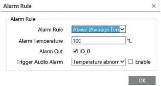
Set the alarm rule and alarm temperature and enable alarm output or audio alarm as needed. For example, select Alarm Rule as Above (Average Temperature), set the alarm temperature to 100°C and check alarm output. Then alarms will be triggered when the average temperature of the target is higher than 100°C.
Note: Before enabling "Trigger Audio Alarm" here, you must enable "Trigger Audio Alarm" in the detection configuration interface of temperature measurement first. Additionally, "Trigger audio alarm" can be enabled respectively for each detection area you set.
- Click "Live" to view the temperature and rule information.
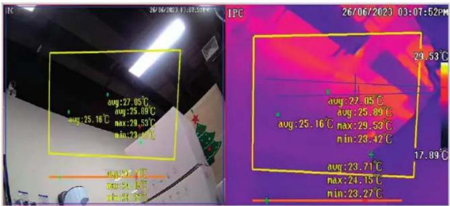
Requirements of Fire detection and temperature measurement
- The thermal camera should be used in a stable indoor environment without wind. Please make sure the monitoring field is far away from any objects that could produce airflow.
- In order to avoid the damage of the sensor, keep the lens of the camera away from the sun.
- The thermal camera should be installed in the highest position of the detection area and the camera should face the detected object.
In the Webcam client, choose "Config" to go to the configuration interface.
Note: Wherever applicable, click the "Save" button to save the settings.
5 - Playback
5.1 - Video Search
You can play the local video record through playback interface. Before playing, please set the storage path of the video record in the local configuration interface and make sure there are record files. After that, click "Playback" tab on the menu toolbar. The following interface will be seen.
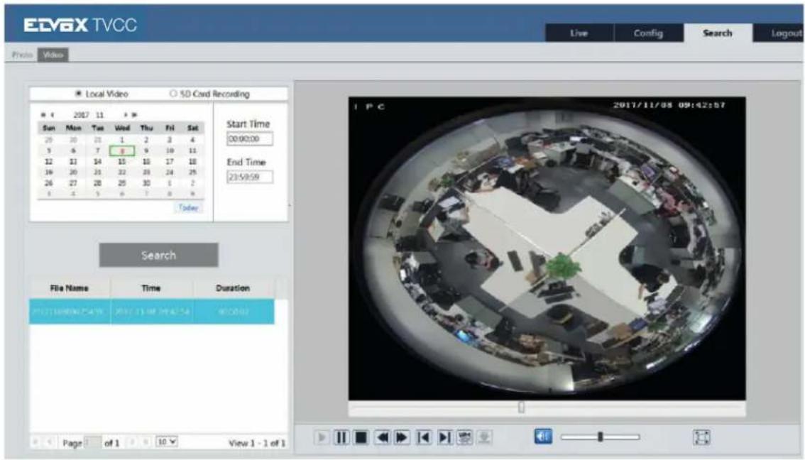
Choose the date and the start time and end time and then click "Search" button to search the record files. Double click the record file to play the record. The descriptions of the buttons on the playback interface are as follows.
| Button Description | |
| Play button. After pausing the video, click this button to continue playing | |
| Pause button | |
| Stop button | |
| Speed down | |
| Speed up | |
| The status icon of playing | |
| Full screen. Click it to display full screen. Double click to exit full screen | |
| Volume | |
| Open/close watermark | |
5.2 - Image Search
Click "Search" icon to search the images saved in the SD card.
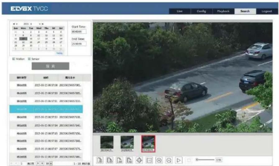
1 - Set time: Select date and choose the start and end time.
2 - Choose "Motion" or "Sensor".
3 - Click "Search" button to search the picture.
4 - Double click a filename or select a filename to view captured pictures.
The descriptions of the icons are as follows.
| Item Button Description | ||
| 1 | [ATTX] | Close: Select certain picture and click this button to close this picture |
| 2 |  | Close all: Click this button to close all pictures viewing |
| 3 |  | Save: Click this button to select the save path of the picture file on the PC for saving the current picture |
| 4 |  | Save all: Click this button to select the save path of the figure files on PC for saving all pictures |
| 5 |  | Proper size: The picture will fit on screen by clicking this button |
| 6 | [93WW] | Actual size: Click this button to display the actual size of the picture as required |
| Item Button Descrizione | ||
| 7 | Zoom in: Click this button to amplify the picture | |
| 8 | Zoom out: Click this button to zoom out the picture | |
| 9 | Slide show photos: Click this button to play the picture in slide show mode | |
| 10 | Stop show: Click this button to stop slide show | |
| 11 | Play speed: Play speed of the slide show | |
IP camera management
5.3 - SD card video search
Click Search → Video → SD Card Recording to go to the interface as shown below. You can search the record saved in the SD card.
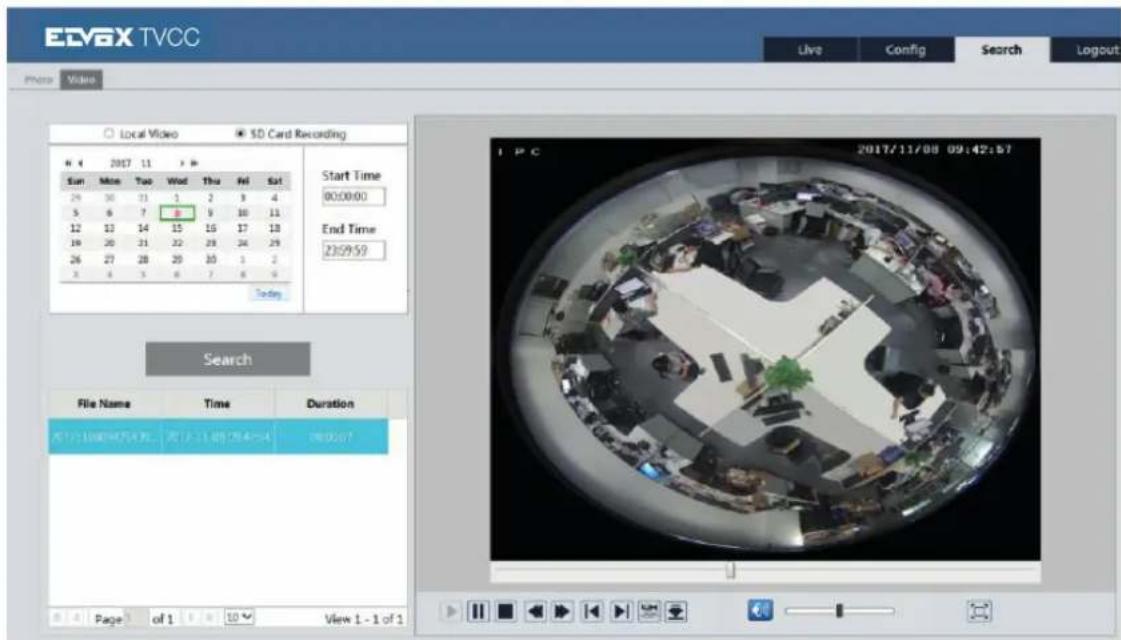
Before you search the SD record, you should trigger the SD recording in motion detection alarm or alarm input alarm (see Motion Detection Trigger or Alarm Input Trigger for detail information). Set the date and the start and end time, select the record type and then click "Search" button to search the record. Double click the searched file name to play the record. Please refer to Local Video Search for the descriptions of the buttons on the playback interface.
Click button to download the record saved in the SD card.
Appendix
Appendix 1 Q & A
Q: How to find my password if I forget it?
A: Reset the device to the default factory settings.
Default IP: 192.168.226.201
User name: admin
Password: 123456
Q: Fail to connect devices through IE browser, why?
A: a. Network is not well connected. Please check the connection and make sure it is connected well.
b. IP is not available. Reset the valid IP.
c. Web port number has been revised: contact administrator to get the correct port number.
d. Exclude the above reasons. Recover default setting by IP-Tool
Note: Default IP: 192.168.226.201, mask number: 255.255.255.0
Q: IP tool cannot search devices, why?
A: It may be caused by the anti-virus software in your computer. Please exit it and try to search device again.
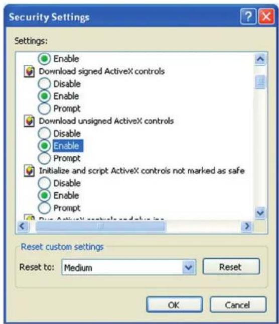
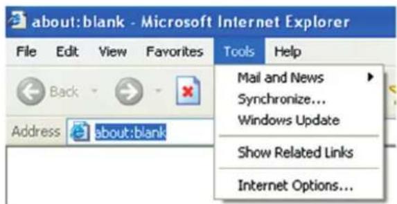
Q: IE cannot download ActiveX control. How can I do?
A. a. IE browser blocks ActiveX. Please try as below.
1 - Open IE browser. Click Tools----Internet Options....
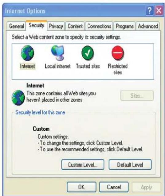
2 - Select Security----Custom Level....
3 - Enable all the sub options under "ActiveX controls and plug-ins".
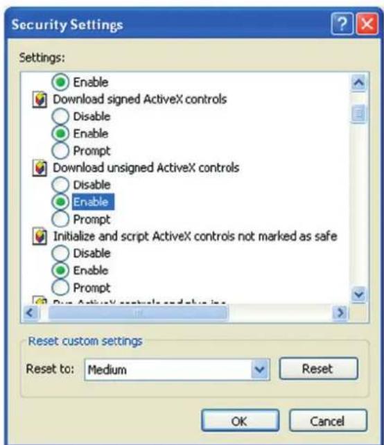
- Then click OK to finish setup.
b. Other plug-ins or anti-virus blocks ActiveX. Please uninstall or close them.
Q: No sound can be heard, why?
A: a. Audio input device is not connected. Please connect and try again.
b. Audio function is not enabled at the corresponding channel. Please check AUDIO item to enable this function.

- Gestione telecamera IP
- - Introduzione
- - Flusso video
- - Maschera video
- - Errore SD card
- - Alarm Out
- Allarme audio
- - Onvif
- - 802.1x
- - HTTPS
- - QoS
- IP Address Filter Setting
- Block the Following MAC Address
- - Ricerca video in SD card
- IP camera management
- Table of Contents - Notes on Safety
- - Introduction
- - IE Remote Access
- - LAN
- - Access through IP-Tool
- - Directly Access through IE
- - WAN
- ▶ Access through static IP
- - Remote Preview
- - The Remote Preview Interface
- - Remote Live Surveillance
- - System Configuration
- - Basic Information
- - Date & Time
- - Local Configuration
- - Storage
- - Set fisheye parameters
- - Image Configuration
- - Display Configuration
- Backlight Compensation:
- Antiflicker:
- - Video Stream
- - OSD Configuration
- - Video Mask
- To set up video mask
- - ROI Configuration
- To set up ROI
- - PTZ Configuration (Fisheye)
- - Alarm Configuration
- - Motion Detection
- Week schedule
- Day schedule
- - SD Card Full
- - SD Card Error
- - IP Address Conflict
- - Cable Disconnection
- - Alarm In
- Alarm Out
- - Alarm Server
- Audio Alarm
- Light Alarm
- - Network Configuration
- - TCP/IPv4
- - Port
- - Central Server
- - DDNS Configuration
- - SNMP
- - RTSP
- - UPNP
- - Mail configuration
- - FTP Setting
- - QoS
- - Security Configuration
- - User Configuration
- Add user:
- Modify user:
- - Online Video User
- - Block and Allow List
- - Security Management
- - Maintenance
- - Import & Export Setting:
- - Default Setting
- - Reboot Device
- - Upgrade
- - Log
- - Temperature Measurement (for thermal cameras only)
- Overlay temperature information:
- Note:
- Requirements of Fire detection and temperature measurement
- - Playback
- - Video Search
- - Image Search
- - SD card video search
- Appendix
- Appendix 1 Q & A
- Q: How to find my password if I forget it?
- Q: Fail to connect devices through IE browser, why?
- Q: IP tool cannot search devices, why?
- Q: IE cannot download ActiveX control. How can I do?
- Q: No sound can be heard, why?
Brand : Vimar
Model : ELVOX 4621.2812ESA
Category : Camera