
CTR 3.0i - Elliptical bike VirtuFit - Free user manual and instructions
Find the device manual for free CTR 3.0i VirtuFit in PDF.


| Product Type | Elliptical Cross Trainer |
| Brand | VirtuFit |
| Model | CTR 3.0i |
| Max User Weight | 150 kg (330 lbs) |
| Power Supply | 9V DC, 500mA adapter (included) |
| Console Display | LCD with time, speed, distance, calories, pulse, RPM, watts |
| Workout Programs | Manual, 12 presets, HRC (55%/75%/90%/TAG), Watt, Body Fat, Recovery |
| Resistance System | Motorized magnetic, adjustable levels via console |
| Heart Rate Monitoring | Hand pulse sensors + Bluetooth wireless receiver (chest strap optional) |
| Pedal Adjustment | 3 positions |
| Transport Wheels | Yes, on front stabilizer |
| Leveling Feet | Adjustable rubber end caps |
| Safety Features | Safety instructions, pacemaker warning, emergency stop? (not specified) |
| Maintenance | Daily wipe; semi-annual bolt check; silicone spray for moving parts |
| Accessories Included | Toolkit (Allen keys, screwdrivers), bottle holder, petroleum jelly |
| Approximate Dimensions | 150 x 70 x 160 cm (estimated) |
| Approximate Weight | 50 kg (estimated) |
| Application Compatibility | iConsole+ and Kinomap (via QR codes in manual) |
| Warranty | Contact dealer for service; warranty excludes improper use |
Frequently Asked Questions - CTR 3.0i VirtuFit
User questions about CTR 3.0i VirtuFit
0 question about this device. Answer the ones you know or ask your own.
Ask a new question about this device
Download the instructions for your Elliptical bike in PDF format for free! Find your manual CTR 3.0i - VirtuFit and take your electronic device back in hand. On this page are published all the documents necessary for the use of your device. CTR 3.0i by VirtuFit.
USER MANUAL CTR 3.0i VirtuFit
CTR 3.0i Elliptical Trainer
User manual
natural_image
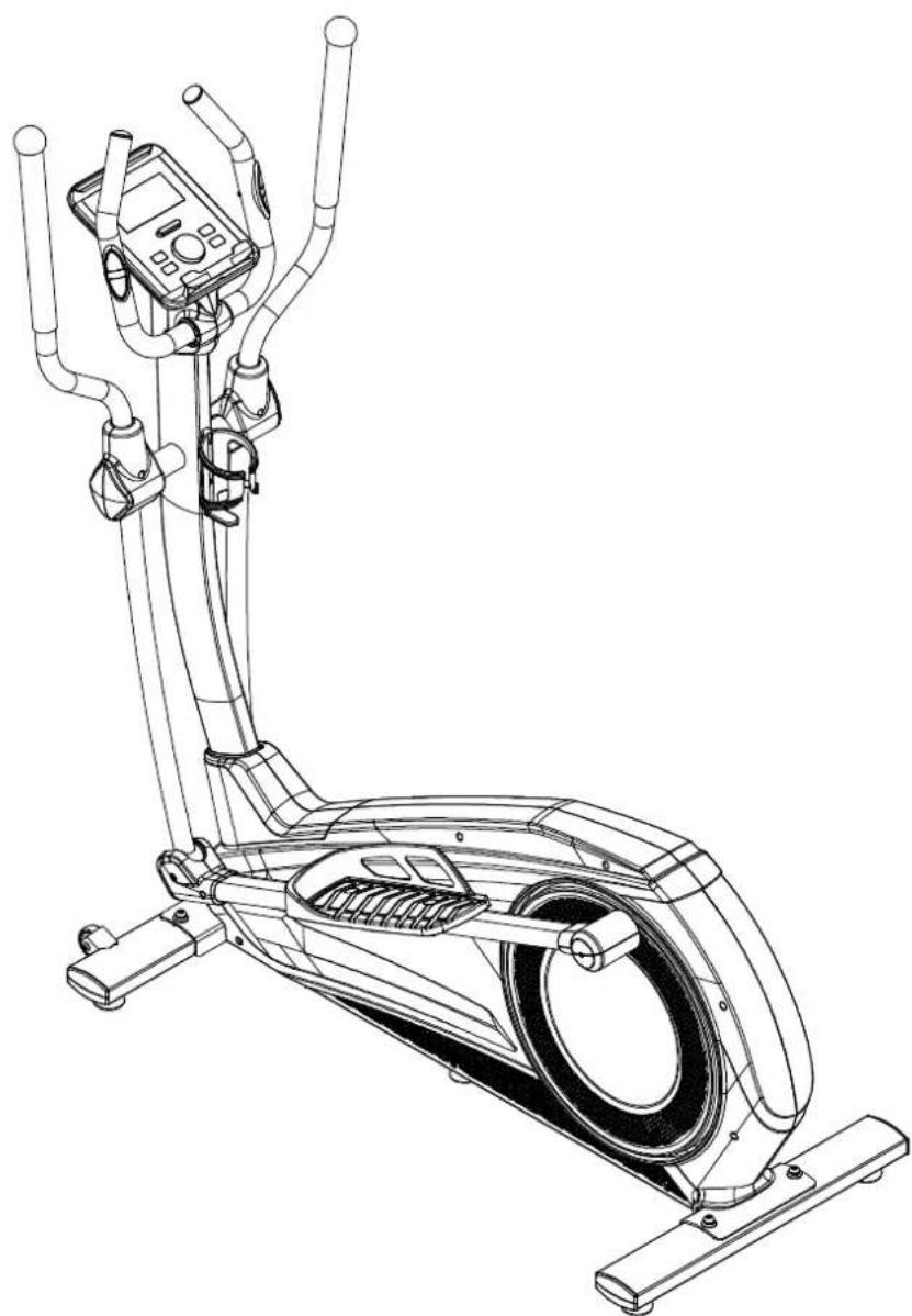
Line drawing of an stationary exercise bike with adjustable arms and control panel (no text or symbols)SAFETY INSTRUCTIONSSAFETY INSTRUCTIONS 3-4
CHECKLIST CHECKLIST 5
ASSEMBLY INSTRUCTIONSASSEMBLY INSTRUCTIONS 6 - 14
ADJUSTMENTS GUIDE ADJUSTMENTS GUIDE 15
Before beginning any exercise program consult your physician. This is especially important for people who are over 35 years old or who have pre-existing health problems. Read all instructions before using any fitness equipment. Do not operate this device without properly fitted guards, as the moving parts can present a risk of serious injury if exposed.
ATTENTION
- It is important to read this entire manual before assembling and using the device. Safe and effective use can only be achieved if the device is assembled, maintained and used properly. It is your responsibility to ensure that all users of the device are informed of all warnings and precautions.
Before starting any exercise program, you should consult your doctor to determine if you have any medical or physical conditions that could put your health and safety at risk, or prevent you from using the device properly. Your doctor's advice is essential if you are taking medication that affects your heart rate, blood pressure or cholesterol level.
- Be aware of your body's signals. Incorrect or excessive exercise can damage your health. Stop exercising if you experience any of the following symptoms: pain, tightness in your chest, irregular heartbeat, extreme shortness of breath, lightheadedness, dizziness or feelings of nausea. If you do experience any of these conditions you should consult your doctor before continuing with your exercise program.
- Keep children and pets away from the device. The device is designed for adult use only.
- Use the device on a solid, flat level surface with a protective cover for your floor or carpet. To ensure safety, the device should have at least 0.5 metres of free space all around it.
– Before using the device, check that the nuts and bolts are securely tightened.
- The safety of the device can only be maintained if it is regularly examined for damage and/or wear and tear.
- Always use the device as indicated. If you find any defective components while assembling or checking the device, or if you hear any unusual noises coming from the device during use, stop immediately. Do not use the device until the problem has been rectified.
- Wear suitable clothing while using the device. Avoid wearing loose clothing that may get caught in the device or that may restrict or prevent movement.
- The max user weight is 150 KGS. Braking ability is independent of speed.
- The device is not suitable for therapeutic use.
- Care must be taken when lifting or moving the device so as not to injure your back. Always use proper lifting techniques and/or seek assistance if necessary.
- Please keep the space at least 1 to 2 meter at the end of base frame to escape any accidents!
- Place the device on a clean and flat surface. Do not place the device on a thick carpet.
- The device is for indoor use and not for outdoor use to prevent damage. Keep the storage location dry, clean and flat. It is forbidden to use the device for purposes other than training.
- Only use the machine in an environment with an ambient temperature between 10 °C and 35 °C. Only store the device at an ambient temperature between 5 °C and 45 °C.
Warranty claim is excluded if the cause of the defect is the result of:
– Maintenance assembly and repair work not carried out by an official dealer.
- In the event of improper use, neglect and / or poor maintenance.
- Failure to maintain the device in accordance with the manufacturer's instructions (see the enclosed manual).
TOOLKIT
When you open the carton, and you will find the below parts in the carton:
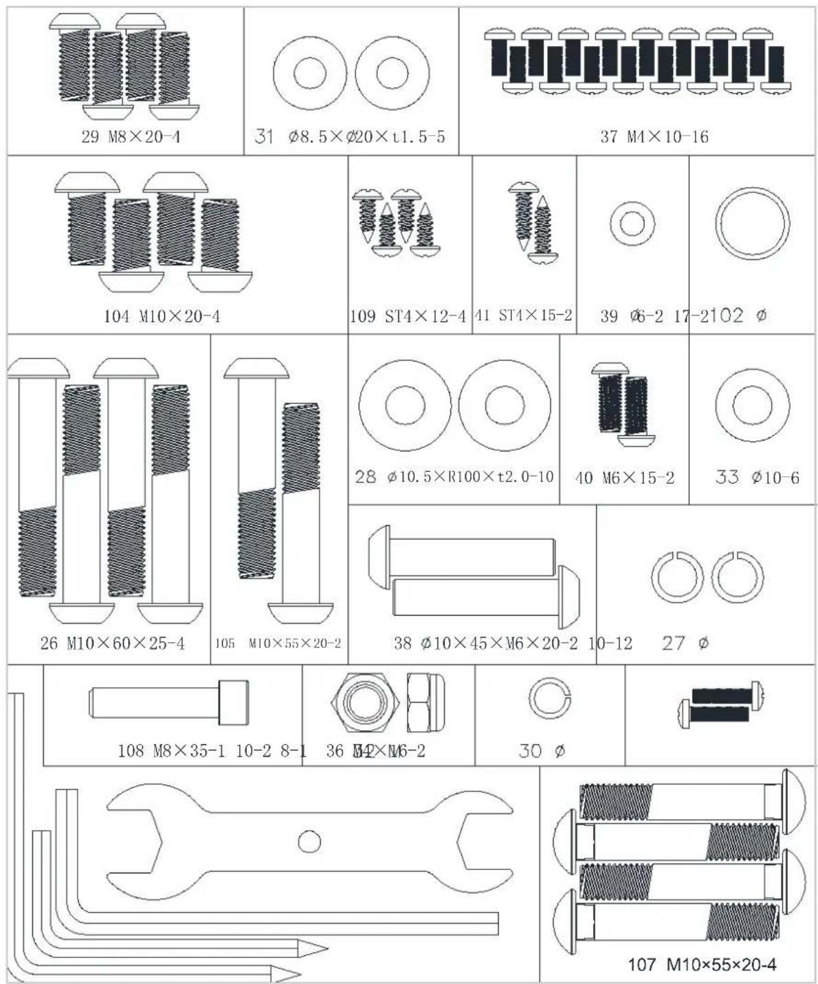
NOTE! Do not connect the appliance to the power before it has been completely assembled.
Missing parts: If you think you are missing certain parts in your package, carefully check the styrofoa and the device. Some parts (bolts, screws, etc.) are already attached to/in the device.
Error message: Ensure that all cables are carefully attached. The aluminum legs are very sensitive and must remain straight. Do you receive an error message after mounting your device? Then you have to straighten these aluminum legs again, this may cause the error message to disappear.
Socket screws: The device contains socket screws, make sure that the allen key is firmly in the bolt before you apply force to the key. In this way you prevent the head of the socket head screw from being rotated.
NOTE! The transport wheels must be mounted on the front of the appliance.
STEP 1

- Attach the front stabilizer (2) to the main frame (1) with curved washer (28), spring washer (27) and Allen C.K.S. half thread screw (26).
STEP 2

- Attach the rear stabilizer (3) to the main frame (1) with curved washer (28), springWasher (27) and Allen C.K.S. half thread screw (26).
STEP 3
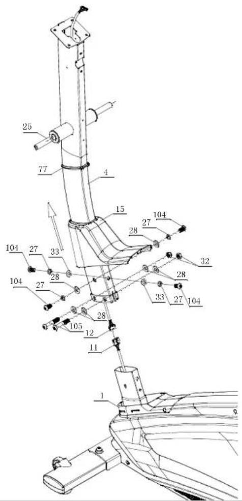
- Attach rubber cover ring (77) to the upper upright post (4). Place the upright post cover (15) to the upper upright post (4).
- Connect motor communication wire (11) and console communication wire (12).
- Attach upper upright post (4) to the main frame (1) with flat washer (33), spring washer (27), Allen C.K.S. full thread screw (104) and Allen C.K.S. half thread screw (105), curved washer (28), spring washer (27) 12 Hex self-locking nut (32). NOTE! Handle, after tightening all bolts.
- Attach upright post cover (15) and upright post decoration strip (77) to the main frame (1). Then install the Axle (25) (pre-assembled).
NOTE! Put the wires in the upright post to prevent folding after connecting all of wires. Do not fully tighten the Bolt yet. Make sure that all screws are in the hexagonal hole.
STEP 4

- Coat the shaft (25) with petroleum jelly from the vaseline supplied.
- Assemble the waved spring washers (102) to the left and right Axle (25). Then attach left body arm (5) and right body arm (6) to shaft (25) with flat washer (31) and Allen C.K.S. full thread screw (29).
- Attach arm cover (16/17) to the left body arm (5) with Philips pan head full thread screw (37).
- Repeat the last step to attach cover (16/17) to the right body arm (6).
STEP 5

• Install the foot pedal (L+R) on the pedal group (L+R), and lock it with carriage screw (107), flat washer (33) hexagon lock nut (32).
• The pedals can be adjusted to three positions.
STEP 6

- Coat the axis of the cross with petroleum jelly with the supplied jar of petroleum jelly (see above image).
- Attach the axle sleeve of left rear pedal supporter (7) to the axle of main frame (1) with Flat washer (31) and Allen C.K.S. Full thread screw (29).
- Attach the axle sleeve of left front pedal supporter (7) to left body arm (5) with Allen. C.K.S. hollow screw(38), flat washer (39) and Allen C.K.S. full thread screw (40).
- Attach the rear cover of pedal supporter (20/21) to left pedal supporter (7) with Philips pan head full thread screw (37). Attach the front cover of pedal supporter (18/19) to left pedal supporter (7) with Philips pan head full thread screw (37) and screw (41).
• Install right pedal supporter (8) with the same way. Put the back side of the pedal supporter(R)(8) on the axle of the main frame(1), use the flat washer(31) and Allen full thread screw (29) to fix it.
STEP 7

- Through handle pulse connection wire(13) out of the upper upright post (4). Unscrew tab (A). Attach handlebars (9) to upright post (4) with flat washer (31), spring washer (30) and Philips pan head full thread screw (36). Tighten tab (A) again.
- Attach bottle holder (24) to upper upright post (4) with Philips pan head full thread screw (36).
- Attach Handle (9) to Upright (4) with M8 x 35 Bolt (29), Spring Washer (30), and Flat Washer (31).
STEP 8

- Loosen the Philips C.K.S. full thread screws (42) off the console and attach console (10) to upper upright post (4) with Philips C.K.S. full thread screws (42).
- Connect console communication wire (12) with the interface of back console. Connect handle pulse communication wire (13) with console outset (14).
- Through left handlebar cover (22) and right handlebar cover (23) out of the handlebar (9). Attach them to the upper upright post (4) with Philips pan head full thread screw (37). Make sure that the cables do not get caught.
- Attach the hood (x) to the front of hood (22+23) with screw (109).
ADAPTER
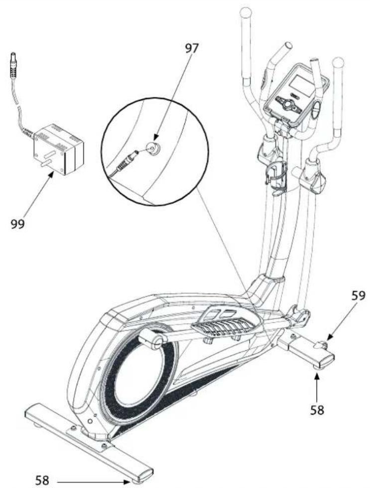
- The adapter is located on the right front side of the device (see image). Attach the adapter to the adapter connection and connect to mains power. You can now use the crosstrainer.
- Do not use the machine until it has been fully assembled and inspected for correct operation in accordance with the user manual..
- Inspect your machine to make sure everything is tight and components are correct are mounted.
LEVELING THE DEVICE
Always make sure that the elliptical cross trainer is on a stable surface. If in doubt, you can always place a rubber mat under your cross trainer so that you get more grip on your floor. If you do need to adjust the crosstrainer slightly, you can compensate the crosstrainer for the uneven surface with a simple turn of the adjustable ends on both sides of the frame.
MOVING THE DEVICE
To move the elliptical, apply pressure to the handlebars until the transport wheels on the front stabilizer touch the ground. With the transport wheels on the ground, you can easily transport the elliptical to the desired location.
5kHz and and pulse sensors
This VirtuFit fitness equipment is provided with hand pulse sensors for measuring the heart rate. The hand pulse sensors are located on the handlebars. The hand pulse sensors are only working if they are touched both at the same time for a couple of seconds. For accurate measurement it is important to have slightly moist hands and to use a constant pressure on the sensors. Too dry or too moist hands can result in less accurate measurement of the heart rate.
HAND PULSE SENSORS
Hand pulse sensors
This VirtuFit fitness equipment is provided with hand pulse sensors for measuring the heart rate. The hand pulse sensors are located on the handlebars. The hand pulse sensors are only working if they are touched both at the same time for a couple of seconds. For accurate measurement it is important to have slightly moist hands and to use a constant pressure on the sensors. Too dry or too moist hands can result in less accurate measurement of the heart rate.
NOTE! Do not use the hand pulse sensor in combination with a wireless heart rate transmitter to prevent errors.
Wireless heart rate monitor (Bluetooth)
This VirtuFit fitness machine is equipped with a wireless heart rate receiver. For heart rate measurement with a wireless heart rate monitor, use a heart rate monitor that works on Bluetooth. With a wireless heart rate monitor it is important that the electrodes are slightly moist and that the heart rate monitor fits well on your body. Refer to your heart rate monitor owner's manual for correct instructions. Incorrect use of the heart rate monitor can cause an abnormal reading.
NOTE!
- A wireless heart rate transmitter does not come standard with this fitness equipment. Contact your dealer for purchasing.
- Do not use the wireless heart rate transmitter in combination with the hand pulse sensors to prevent errors.
WARNING
- Consult a physician if you have a pacemaker, before using a wireless heart rate transmitter.
- If there are more than one heart rate measurement devices in one room, please make sure to keep distance to the other devices to prevent inaccurate measurement or errors.
- Alway try to keep the wireless heart rate transmitter in a close distance of 1 meter from the console.
• Always wear a wireless heart rate transmitter directly on the body under your clothes.
Safe and effective use can only be achieved if the device will be assembled and maintained well. It is your responsibility to ensure that the equipment is regularly maintained. Parts that are already used and / or damaged must be replaced before continuing using. The rower machine may only be used indoors and stored away, prolonged exposure to weathering and changes in temperature / humidity can have a serious impact on the electrical components and moving parts of the device.
DAILY MAINTENANCE
- Clean and remove sweat after each use Do not use aggressive cleaning agents and ensure that the device remains free of moisture.
- Check that the rail and the wheels under the seat are free from dust and dirt.
SEMI-ANNUAL MAINTENANCE
- Inspect all bolts and nuts in connection with moving parts of the device, tighten as required.
- Check the mobility of moving parts and components of the use equipment, silicone spray if necessary.
CLEANING
WARNING
Before cleaning the machine, please make sure the power has been switched off.
Cleaning: General cleaning of the device will extend the life of the elliptical trainer. Hold clean the elliptical trainer by dusting regularly.
In addition, wear clean shoes to reduce the risk of contamination of the elliptical trainer. Remove the hood at least once a year to vacuum underneath.
EXTEND SERVICE LIFE
- The upright is secured with Allen screws, make sure that the bolts are tight at all times. If the bolts are not tight enough anymore, this can cause cracking.
- If a main switch is attached to the appliance (on/off), it should always be used after use be turned off.
Display shows no values
If the display does not show any values, you can try to check the sensor cables and the cables in the back of the display. If this still does not work, you can move the sensor slightly.
The device beeps
If necessary, lubricate parts with silicone spray. Check that all nuts and bolts are tightened. It may be that a screw is too loose or too tight, this creates friction and makes the device appear to beep. If this is the case, try to find out exactly where the beep comes from and then tighten or loosen this screw. It must always be possible to loosen the screws with your hands. If this is not possible, the screw is too tight.
No resistance
First check whether you can hear the motor running. You will hear the motor running briefly when you increase or decrease the resistance. If you hear the engine running, all electronics are in order, but the V-belt is probably over. You can then open the housing and put the V-belt back on it. If you do not hear the motor running, it is possible that the motor or the display is defective. First check whether the cable running upwards in the pipe is still properly connected.
Ticking sound
It is possible that the flywheel (in the housing) comes against a cable with each pedaling movement. This may be disturbing but will not permanently damage your crosstrainer.
To fix this, open the housing and move the cable or fix it with for example a tie wrap.
Heart rate display is not functioning
There can be various reasons for this:
- The sensor cables that run from the heart rate sensor to the display are not properly installed or have become detached during use.
• The sensors may become damp, dirty or greasy. So you have to clean them regularly.
The console is not working
If there is no signal when pedaling, check if the cable is properly attached.
- This unit requires a 9V, 500mA adapter. If the meter does not display properly, pull the Unplug the power cord and plug it in again.
- When the user stops pedaling for 4 minutes, the computer enters power saving mode, all settings and training data are saved until the user starts again with train.
- If the computer shows abnormal values, unplug the power cord from the power outlet, so that the power is off and reconnect it.
ERROR CODES
E1
Console is not receiving a FAT test signal, grasp both sensors securely.
E2
Check if the motor exceeds the range of the console.
E4
The set age, height and weight exceed the set range of the console, please set it based on the actual values of the user.
E5
Check that the 12-pin (9-pin) wire between the console and the machine is properly connected without breaking contact.
E7
Check that the 12-pin (9-pin) wire between the console and the machine is properly connected, without breaking the contact (with CD motor).
CONSOLE
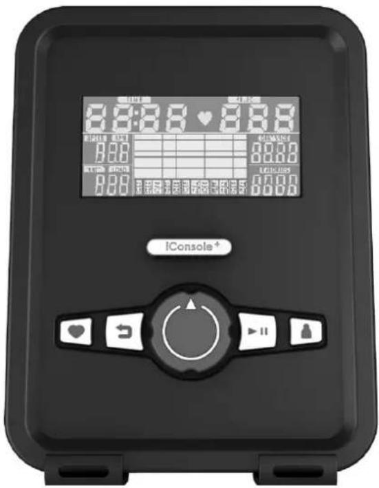
| BUTTON FUNCTION | |
| ENTER | In STOP mode, press it for all setting confirmation and enter into program. |
| WHEEL UP/ DOWN | Increase or decrease the resistance level and setting selection. |
| RESET | Press the button for 2 seconds. The computer will restart at from the setting of the user.Return to the main menu while setting one training value or during stop mode. |
| START/STOP | Start or stop the workout. |
| RECOVERY | Test the heart rate recovery status. |
| BODYFAT | Test body fat and BMI. |
FUNCTIONS
| FUNCTION DESCRIPTION | |
| TIME | Workout time displayed during exercise. Range 0:00 ~ 99:59 |
| SPEED | Workout speed displayed during exercise. Range 0.0 ~ 99.9 |
| DISTANCE | Workout distance displayed during exercise. Range 0.0 ~ 99.99 |
| CALORIES | Burned calories during workout display. Range 0 ~ 9999 |
| PULSE | Pulse bpm displayed during exercise. Pulse alarm when over preset target pulse. |
| RPM | Rotation per minute. Range 0 ~ 999. |
| WATTS | Workout power consumption. Setting Range: 0-10 ~ 350; Display Range:0~999 |
| MANUAL | Manual mode workout. |
| PROGRAM | 12 PROGRAM selection. |
| USER | User creates resistance level profile. |
| HRC | Target HR training mode. |
| WATT | Watt constant training mode. |
OPERATION
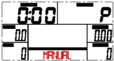
MANUAL MODE
Press START in main menu may start workout in manual mode.
- Press UP or DOWN to select workout program, choose Manual and press ENTER KRY to enter.
- Press UP or DOWN to preset TIME.DISTANCE.CALORIES.PULSE and press ENTER to confirm.
- Press START/STOP keys to start workout. Press UP or DOWN to adjust load level.
- Press START/STOP keys to pause workout. Press RESET to reverse to main menu.
PROGRAM MODE
- Press UP or DOWN to select workout program, choose Program and press ENTER KEY to enter.
- Press UP or DOWN to preset workout TIME.
- Press START/STOP keys to start workout. Press UP or DOWN to adjust load level.
- Press START/STOP keys to pause workout. Press RESET to reverse to main menu.

H.R.C. MODE
- Press UP or DOWN to select workout program, choose H.R.C. and press ENTER KEY to enter.
- Press UP or Down to select 55%.75%.90% or TAG (TARGET H.R.) (default: 100).
- Press UP or DOWN to preset workout TIME.
- Press START/STOP button to start or stop workout. Press RESET to reverse to main menu.
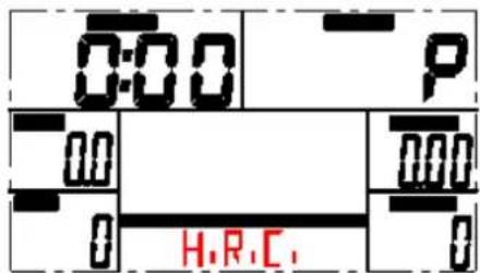
NOTE! During this exercise, the heart rate sensors should be held or a heart rate belt worn.
WATT MODE
- Press UP or DOWN to select workout program, choose WATT and press ENTER KEY to enter.
- Press UP or DOWN to preset WATT target. (default: 120)
- Press UP or DOWN to preset TIME.
- Press START/STOP button to start or stop workout. Press RESET to reverse to main menu.
RECOVERY
- When pulse value display on the computer (hold handgrip or wear chest strap), press RECOVERY button.
- All function display will stop except TIME"starts counting down from 00:60 to 00:00. When TIME counts down to 0, screen will display your heart rate recovery status with the FX (X=1\~6). F1 is the best, F6 is the worst. (See below chart) (Press the RECOVERY button again to return the main display.)
- During RECOVERY, user may press RECOVERY button to back to main menu.
- Without pulse inputted, it is invalid to press RECOVERY button.
| 1.0 | OUTSTANDING |
| 1.0 < F > 2.0 | EXCELLENT |
| 2.0 < F > 2.9 | GOOD |
| 3.0 < F > 3.9 | FAIR |
| 4.0 < F > 5.9 | BELOW AVERAGE |
| 6.0 | POOR |
BODY FAT
- When workout stop, press BODY FAT key.
- Hold on handgrip, after 8 seconds, computer will show BMI, FAT% and fat symbol.
- Press BODY FAT key again reverse to main menu.
B.M.I. (Body Mass Index) integrated
| BMI SCALE LOW LOW/MED MEDIUM MED/HIGH | ||||
| RANGE | < 20 20 - 24 24.1 - 26.5 > 26.5 | |||
| SYMBOL | - | + | ▲ | ◆ |
| FAT% | LOW | LOW/MED | MEDIUM | MED/HIGH |
| MALE | <13% | 13% - 25.9% | 26% - 30% > 30% | |
| FEMALE | < 23% | 23% - 35.9% | 36% - 40% > 40% | |
INSTRUCTION
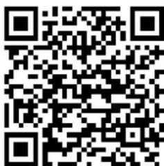
- QR code scanner app is required to scan the QR code with an Android or IOS phone or tablet. This app can be downloaded in the App Store or Google Play Store.
- Scan one of the QR codes below to go directly to the place in the App Store or Google Play Store where the app is located and can be downloaded.
- Scan the QR code on the right to go to the user manual of the app. The manual describes step by step how the app should be connected to the device, how the app works and what the options are.
ICONSOLE+

APP STORE
ICONSOLE+
GOOGLE PLAY
ICONSOLE+

USER MANUAL
ICONSOLE+
KINOMAP

APP STORE
KINOMAP

GOOGLE PLAY
KINOMAP

USER MANUAL
KINOMAP
VirtuFit does not provide service for third-party fitness apps such as Kinomap, iConsole, FitShow etc.. If you encounter any troubles with a third-party fitness app, please contact the app developer.


| # DESCRIPTION QTY. | ||
| 1 Main Frame 1 | ||
| 2 Front stabilizer 1 | ||
| 3 Rear stabilizer 1 | ||
| 4 Upper upright post 1 | ||
| 5 Body arm (L) 1 | ||
| 6 Body arm (R) 1 | ||
| 7 Pedal supporter (L) 1 | ||
| 8 Pedal supporter (R) 1 | ||
| 9 Handlebars 1 | ||
| 10 | Console | 1 |
| 11 | Motor communication wire | 1 |
| 12 | Console communication wire | 1 |
| 13 | Handle pulse communication wire | 2 |
| 14 | Console outset | 2 |
| 15 | Upright post cover | 1 |
| 16 | Body arm cover | 2 |
| 17 | Body arm cover | 2 |
| 18 | Front pedal supporter cover | 2 |
| 19 | Front pedal supporter cover | 2 |
| 20 | Rear pedal supporter cover | 2 |
| 21 | Rear pedal supporter cover | 2 |
| 22 | Handlebar cover (L) | 1 |
| 23 | Handlebar cover (R) | 1 |
| 24 | Bottle holder | 1 |
| 25 | Axle Φ17*339.5 | 1 |
| 26 | Allen C.K.S. screw M10*60*25 | 4 |
| 27 | Spring washer Φ10 8 | |
| 28 | Curved washer Φ10.5*R100*t2.0 | 10 |
| 29 | Allen C.K.S. screw M8*20 | 6 |
| 30 | Spring washer Φ8 | 2 |
| # DESCRIPTION QTY. | ||
| 31 | Flat washer Φ8.5*Φ20*t1.5 | 6 |
| 32 | Hex self-locking nut M10 | 6 |
| 33 | Flat washer Φ10 | 6 |
| 34 | Idler stopper 1 | |
| 35 | Idler stopper 1 | |
| 36 | Philips screw M4*16 | 2 |
| 37 | Philips pan head screw M4*10 | 16 |
| 38 | Allen C.K.S. screw Φ10*45*M6*20 | 2 |
| 39 | Flat washer Φ6 2 | |
| 40 | Allen C.K.S. hollow screw M6*15 | 2 |
| 41 | Philips C.K.S. self-tap screw ST4*15 | 2 |
| 42 | Philips C.K.S. screw M5*10 | 4 |
| 43 | Plastig buckle Φ12.4*13 | 12 |
| 44 | Philips C.K.S. self-tap. screw ST4*10 | 12 |
| 45 | Crank | 2 |
| 46 | Hexagon screw M10*55*20 | 2 |
| 47 | Hexagon screw M10*55*20 | 2 |
| 48 | Flat key 5*5*15 | 2 |
| 49 | Allen C.K.S. screw M6*15 | 2 |
| 50 | Flat washer Φ8*Φ30*t3.0 | 2 |
| 51 | Roller | 1 |
| 52 | Idler connection tube Φ15*30 | 1 |
| 53 | Hexagon nut M8 | 2 |
| 54 | Locknut M8 6 | |
| 55 | Tensioner | 1 |
| 56 | Retaining ring shaft Φ10 | 1 |
| 57 | End cap | 4 |
| 58 | Footrest | 5 |
| 59 | Wheels | 2 |
| 60 | Allen C.K.S. screw Φ8*33*M6*15 | 2 |
| # DESCRIPTION QTY | ||
| 61 Hexagon screw M5×60 1 | ||
| 62 Hexagon nut M5 1 | ||
| 63 Deep groove ball bearing 6004-2RS 2 | ||
| 64 Fixed magnetic induction 1 | ||
| 65 Philips self-tap. screw ST4×12 1 | ||
| 66 Crankshaft 1 1 | ||
| 67 Crankshaft 3 1 | ||
| 68 Crankshaft Φ20×115 1 | ||
| 69 Belt pulley Φ308×22 1 | ||
| 70 Crankshaft 2 1 | ||
| 71 Fixed magnet set 1 | ||
| 72 Magnetic bed. fixed axle Φ12×50 1 | ||
| 73 Brake tension spring 1 | ||
| 74 Magnet motor | 1 | |
| 75 Double flywheel Φ280/9KG | 1 | |
| 76 Motor belt 540PJ6 | 1 | |
| 77 Standing bar decoration 102×57×8 | 1 | |
| 78 Platic cover Φ42.5×30 | 2 | |
| 79 Handle pulse | 2 | |
| 80 Philips C.K.S. self-tap. screw ST4×20 2 | ||
| 81 Plug Φ28×t1.5 | 2 | |
| 82 Foam handle Φ32×t3.0×480 | 2 | |
| 83 Retaining ring for shaft Φ12 | 2 | |
| 84 Pedal (L) 406×187×74 | 1 | |
| 85 Pedal (R) 406×187×74 | 1 | |
| 86 Lock bolt M10×55×25 | 4 | |
| 102 | Corrugated hoist ring Φ17 | 2 |
| 104 | Allen C.K.S. screw M10×20 | 4 |
| 105 | Allen C.K.S. screw M10×55×20 | 2 |
| 107 | Bolt M10×55×20 4 | |
| # DESCRIPTION QTY | ||
| 108 | Allen full thread bolt M8x30 | 1 |
| 109 | Philips C.K.S. self-tapping ST4x12 | 4 |
| 110 | Handle bar front cover | 1 |
A successful exercise program consists of a warm-up, aerobic exercise, and a cool-down. Do the entire program at least two and preferably three times a week, resting for a day between workouts. After several months, you can increase your workouts to four or five times per week.
WARMING UP
The purpose of warming up is to prepare your body for exercise and to minimize injuries. Warm up for two to five minutes before strength-training or aerobic exercising. Perform activities that raise your heart rate and warm the working muscles. Activities may include brisk walking, jogging, jumping jacks, jump rope, and running in place.
STRETCHEN
Stretching while your muscles are warm after a proper warm-up and again after your strength or aerobic training session is very important. Muscles stretch more easily at these times because of their elevated temperature, which greatly reduces the risk of injury. Stretches should be held for 15 to 30 seconds.
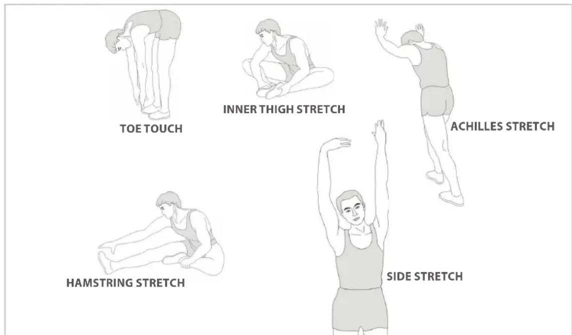
COOLING DOWN
The purpose of cooling down is to return the body to its normal or near normal, resting state at the end of each exercise session. A proper cool-down slowly lowers your heart rate and allows blood to return to the heart.
virtufit
For questions or missing parts please contact your dealer.


- User manual
- ATTENTION
- Warranty claim is excluded if the cause of the defect is the result of:
- TOOLKIT
- STEP 1
- STEP 2
- STEP 3
- STEP 4
- STEP 5
- STEP 6
- STEP 7
- STEP 8
- ADAPTER
- LEVELING THE DEVICE
- MOVING THE DEVICE
- 5kHz and and pulse sensors
- HAND PULSE SENSORS
- Wireless heart rate monitor (Bluetooth)
- NOTE!
- WARNING
- DAILY MAINTENANCE
- SEMI-ANNUAL MAINTENANCE
- CLEANING
- EXTEND SERVICE LIFE
- Display shows no values
- The device beeps
- No resistance
- Ticking sound
- Heart rate display is not functioning
- The console is not working
- ERROR CODES
- E1
- E2
- E4
- E5
- E7
- CONSOLE
- OPERATION
- MANUAL MODE
- PROGRAM MODE
- H.R.C. MODE
- WATT MODE
- RECOVERY
- BODY FAT
- INSTRUCTION
- WARMING UP
- STRETCHEN
- COOLING DOWN
- virtufit
Brand : VirtuFit
Model : CTR 3.0i
Category : Elliptical bike