
82-9601 - Car hands-free kit Metra - Free user manual and instructions
Find the device manual for free 82-9601 Metra in PDF.


| Product Type | Speaker adapter kit |
| Brand | Metra |
| Model | 82-9601 |
| Compatibility | Harley-Davidson FL models 1998-2013 (FLH batwing, Roadglide sharknose) |
| Speaker Size | 6.5" to 6.75" aftermarket speakers |
| Components Included | 2 speaker adapters, 6 screws (#8 x 1" Pan-head Phillips) |
| Tools Required | Panel removal tool, Phillips screwdriver, Socket wrench (T-25, T-27, 6mm or 3/16 hex) |
| Mounting Location | Factory speaker locations in fairing |
| Installation Complexity | Moderate (requires fairing disassembly) |
| Battery Disconnection | Recommended before installation |
| Material | Plastic adapters, steel screws |
| Approximate Weight | 0.5 lbs (0.23 kg) |
| Dimensions (each adapter) | Approx. 6.75" diameter |
| Color | Black (typical) |
| Purpose | Mount aftermarket speakers into factory locations |
| Additional Notes | Follow detailed installation instructions; disassembly varies by fairing type |
Frequently Asked Questions - 82-9601 Metra
User questions about 82-9601 Metra
0 question about this device. Answer the ones you know or ask your own.
Ask a new question about this device
Download the instructions for your Car hands-free kit in PDF format for free! Find your manual 82-9601 - Metra and take your electronic device back in hand. On this page are published all the documents necessary for the use of your device. 82-9601 by Metra.
USER MANUAL 82-9601 Metra
INSTALLATION INSTRUCTIONS FOR PART 82-9601
APPLICATIONS
Harley-Davidson 1998-2013
(FL models with fairings)
82-9601
KIT FEATURES
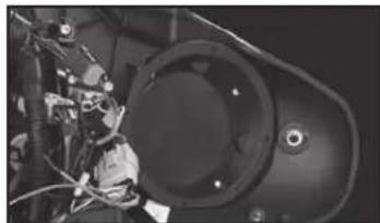
- Mounts aftermarket 6.5" to 6.75" speakers into factory speaker locations.
natural_image
Close-up of a mechanical device with wires and a central circular component (no visible text or symbols)KIT COMPONENTS
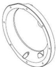
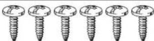
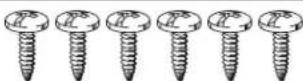
• A) (2) speaker adapters • B) (6) #8 x 1" Pan-head Phillips screws
A
natural_image
Technical line drawing of a circular mechanical component with mounting holes and internal features (no text or symbols)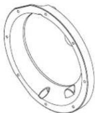
natural_image
Technical line drawing of a circular mechanical component with mounting holes (no text or symbols)B
TOOLS REQUIRED
- Panel removal tool • Phillips screwdriver • Socket Wrench (T-25, T-27, 6mm or 3/16 hex)
Table of Contents
Fairing Disassembly
- Harley-Davidson FLH, batwing fairing ... 1998-2013 ....2-3
- Harley-Davidson Roadglide, sharknose fairing ... 1998-2013 ....4-5
Kit Assembly 6
CAUTION: Metra recommends disconnecting the negative battery terminal before beginning any installation. All accessories, switches, and especially air bag indicator lights must be plugged in before reconnecting the battery or cycling the ignition.
NOTE: Refer to the instructions included with the aftermarket radio.

82-9601
Fairing Disassembly
FLH/Batwing models:
- Cover the front fender.
- Remove (2) T-27 Torx bolts from inner fairing (under mirrors) (Figure A, step 2)
- Remove (2) T-27 Torx bolts from outer edges of inner fairing near the fork tubes (facing forward) (Figure A, step 3)
- Remove (3) T-27 Torx bolts from bottom edge of windshield. (Figure A, step 4)
NOTE: Windshield and fairing will be loose once these screws are removed. Use extreme caution not to damage fairing or windshield. - Remove windshield taking caution that the outer fairing is loose.
Continued on next page
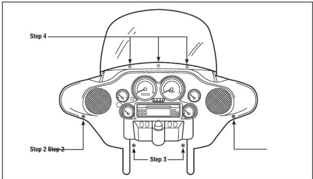
(Figure A)

82-9601
Fairing Disassembly
FLH/Batwing models: (cont.)
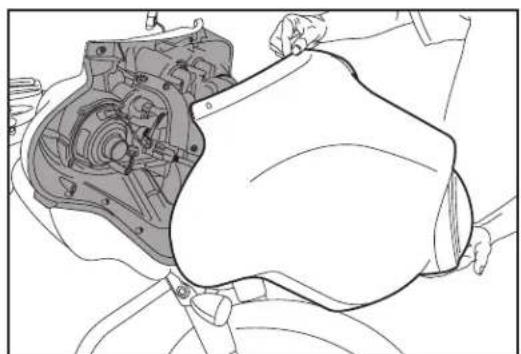
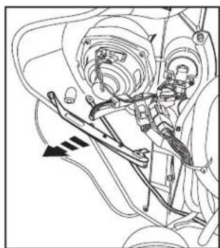
- Lift away and unplug headlight to remove outer fairing. (Figure B)
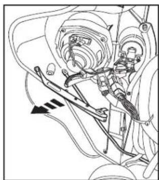
- Unbolt and remove inner fairing support brackets from each side (3/16" Allen & T-25 Torx screws)
Note the Torx screw is also a shared speaker screw. (Figure C)
- Remove the remaining speaker screws and the speaker.
Continue to kit assembly
natural_image
Technical line drawing of a mechanical assembly with internal components (no text or symbols)(Figure B) (Figure C)
natural_image
Mechanical assembly diagram showing interconnected components and motion arrows (no text or labels)
82-9601
Fairing Disassembly
Roadglide/Sharknose models
- Loosen (6) T-25 Torx bolts from bottom, middle and top of left and right sides of the inner fairing. (Figure A)
Continued on next page
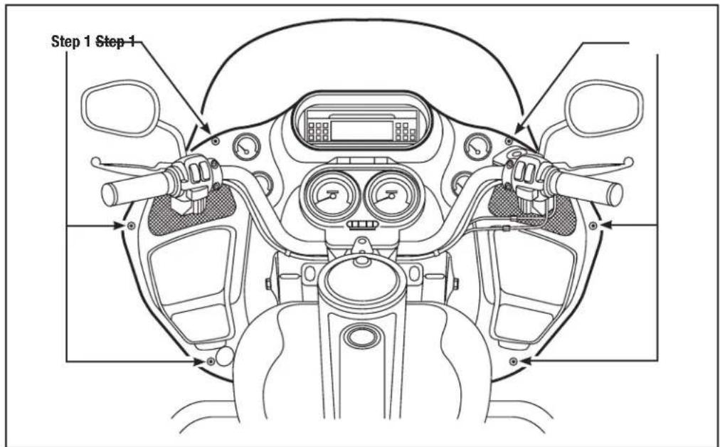
(Figure A)

82-9601
Fairing Disassembly
Roadglide/Sharknose models: (cont.)
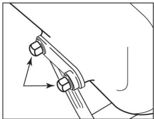
- Use a 1/2" socket or box wrench to remove the (2) acorn nuts that hold each turn signal at the lower fairing. Let the signals hang loose. (Figure B)
- Lift away the fairing, unplug the headlights and remove.
- Remove the speaker screws and the speaker.
Continue to kit assembly
natural_image
Mechanical linkage diagram showing two bolts and motion arrows (no text or symbols)(Figure B)

82-9601
Kit Assembly
-
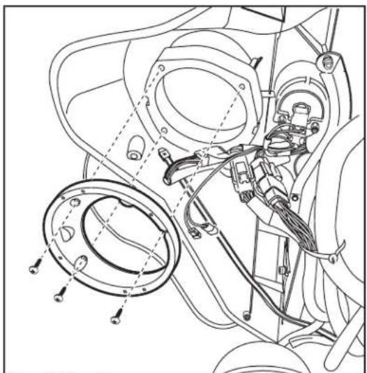
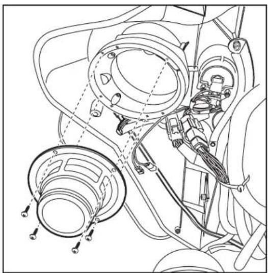
Using 3 of the screws in the provided hardware, mount the speaker adapter to the inner fairing. The 4th inner bottom screw locations are not used on FLH/batwing models. For Road Glide models, rotate the adapter until the notches in the adapter do not hit the factory mounting posts and the flat spots on the outside of the adapter are toward the outer edge of the fairing. (Figure A)
-
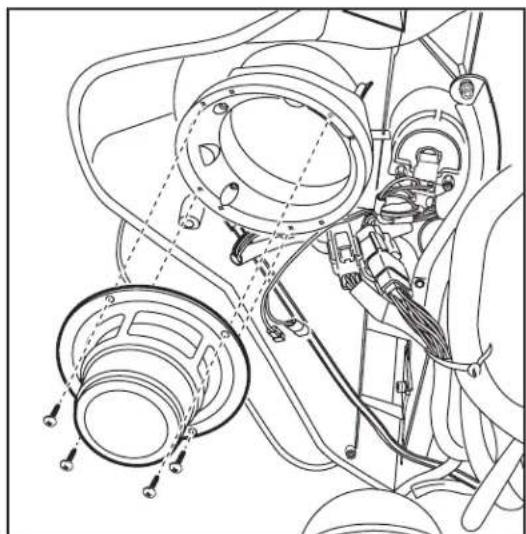
Mount the new speaker with the hardware provided with the speakers. (Figure B)
natural_image
Technical line drawing of a mechanical assembly with no visible text or symbols(Figure A) (Figure B)
natural_image
Technical line drawing of a mechanical assembly with hoses, clamps, and wiring (no text or symbols)Metra
82-9601

INSTALLATION INSTRUCTIONS FOR PART 99-9601


KNOWLEDGE IS POWER
Enhance your installation and fabrication skills by enrolling in the most recognized and repurposed.
enrolling in the most recognized and resp. mobile electronics school in our industry.
Log onto www.installerinstitute.com or call
800-354-6782 for more information and take steps toward a better tomorrow.

Metra recommends MECP
certified technicians

natural_image
Close-up of a mechanical component with wires and a circular housing (no visible text or symbols)COMPONENTES DEL KIT
natural_image
Two identical mechanical flange components with mounting holes and central slots (no text or symbols)B
(Figura A)

82-9601
Desensamble del carenado
Modelos FLH/alas de murciélago (cont.)
natural_image
Technical line drawing of a mechanical assembly with internal components (no text or symbols)(Figura B) (Figura C)
natural_image
Mechanical assembly diagram showing interconnected components and motion arrows (no text or labels)
82-9601
Desensamble del carenado
Modelos Roadglide/Sharknose
natural_image
Mechanical linkage diagram showing two bolts and motion arrows (no text or symbols)(Figura B)

82-9601
Ensamble del kit
natural_image
Technical line drawing of a mechanical assembly with flanges and wiring (no text or symbols)(Figura A) (Figura B)
natural_image
Technical line drawing of a mechanical assembly with hoses, clamps, and wiring (no text or symbols)Metra™
82-9601

- Harley-Davidson 1998-2013
- KIT FEATURES
- KIT COMPONENTS
- TOOLS REQUIRED
- Table of Contents
- Fairing Disassembly
- FLH/Batwing models:
- FLH/Batwing models: (cont.)
- Roadglide/Sharknose models
- Roadglide/Sharknose models: (cont.)
- Kit Assembly
- COMPONENTES DEL KIT
- Desensamble del carenado
- Modelos FLH/alas de murciélago (cont.)
- Modelos Roadglide/Sharknose
- Ensamble del kit
Brand : Metra
Model : 82-9601
Category : Car hands-free kit