
PathFindIR II - Uncategorized FLIR - Free user manual and instructions
Find the device manual for free PathFindIR II FLIR in PDF.


| Product Type | Thermal Imager |
| Brand | FLIR |
| Model | PathFindIR II |
| Sensor Type | 320 x 240 Uncooled Microbolometer |
| Field of View | 24° (h) x 18° (v) |
| Spectral Band | 8-14 microns (LWIR) |
| Video Output | NTSC |
| Power Requirements | 12 VDC |
| Power Consumption | 2 W (6 W with heater on), 1.8 A max system current |
| Operating Temperature | -40°C to 80°C |
| Camera Weather Resistance | Hermetically Sealed, Automotive Qualified |
| ECU Weather Resistance | Non-Hermetic; Passenger Compartment mount required |
| Window | High-Impact Resistant Optic with Built-in Automatic Heating Element, Replaceable |
| Camera Dimensions | 2.6" x 3.4" x 3.2" (60 x 86 x 82 mm) |
| Camera Weight | 0.6 lb (300 g) |
| ECU Dimensions | 5.8" x 4.3" x 0.9" (148 x 110 x 24 mm) |
| ECU Weight | 0.7 lb (350 g) |
| Mounting Height | 19-31 inches, optimal 25.5 inches (65 cm ± 15 cm) |
| Pedestrian and Animal Detection | Yes, requires precise alignment |
| Installation Kit (optional) | Includes mounting bracket and ECU bracket |
Frequently Asked Questions - PathFindIR II FLIR
User questions about PathFindIR II FLIR
0 question about this device. Answer the ones you know or ask your own.
Ask a new question about this device
Download the instructions for your Uncategorized in PDF format for free! Find your manual PathFindIR II - FLIR and take your electronic device back in hand. On this page are published all the documents necessary for the use of your device. PathFindIR II by FLIR.
USER MANUAL PathFindIR II FLIR
natural_image
Close-up of a black square mechanical component with central circular bore and mounting base (no visible text or symbols)PathFindIR II
QuickStart Guide
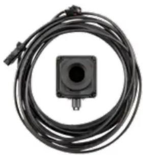
natural_image
Coiled black cable with a central square component and connector (no visible text or symbols)Ready
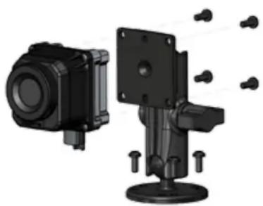
natural_image
3D mechanical assembly diagram showing two components with mounting flanges and bolt holes (no text or symbols)Set
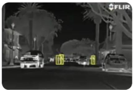
natural_image
Night street scene with cars and palm trees, no visible text or symbolsGo...
Quick Start Guide
Installation of the PathFindIR II is quick and easy. Just mount the camera and ECU, connect to a 12v power source and a video monitor and you're done.
For the complete user manual and install video please go to our website at the following link: http://www.flir.com/pf2docs
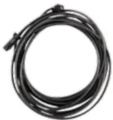
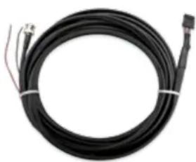
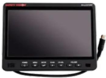
1. Before you begin, make sure you've got all of the parts you'll need. Your PathFindIR II kit should include the following items:
(along with 4 screws for mounting the camera)
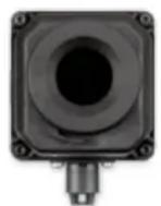
PathFindIR Camera Video Monitor
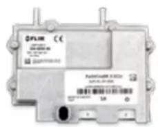
ECU
natural_image
Coiled black cable or wire with connectors, no visible text or symbolsPathFindIR To ECU Cable
natural_image
Coiled black cable with connectors and wires, no visible text or symbolsPower/Video Cable
If you purchased the optional Installation Kit, you will also have:
natural_image
Front view of a black rectangular electronic device with a cable and control buttons (no visible text or symbols)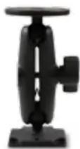
PathFindIR
Mounting Bracket
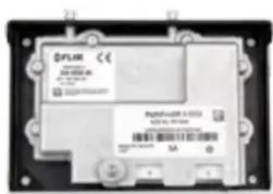
ECU Bracket (with ECU Installed)
3. First, you need to select an acceptable mounting location for the camera head.
- Mount the camera in the front of the car behind the grille, but make sure it has no obstructions in its view.
- Don't mount the camera inside the passenger compartment, because it can't see through glass.
-
To get the best performance out of the camera and its onboard pedestrian and animal detection algorithms, you need to make sure the camera is mounted according to factory specifications (see user guide for details).
-
The camera should be mounted between 19 and 31 inches high, with the optimal height above the ground being 25 and a half inches high (65cm ±15cm). Also keep in mind that if you can mount the camera higher, you'll cut down the chances of the camera getting damaged by rocks or other road debris.
- Make sure that the camera won't be exposed to fast temperature changes, so keep it as far from the engine as possible.
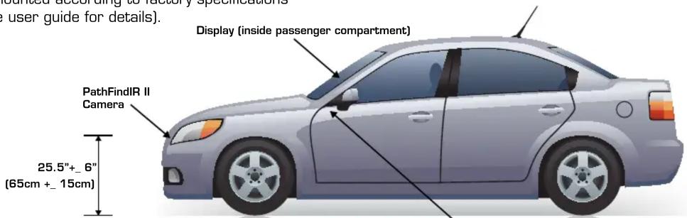
ECU (inside passenger compartment
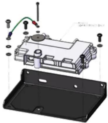
- Mount the camera head with the four M5 screws in the camera kit. You can either fashion your own mounting bracket, or use the bracket included in the optional Installation kit (shown below).
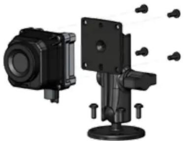
natural_image
3D rendering of two black mechanical components with mounting base and mounting holes (no text or symbols visible)6 Route the ECU cable from the camera head to the ECU in its mounted location. Align the connectors and seat them firmly together. The connector is designed so it can only be attached one way.
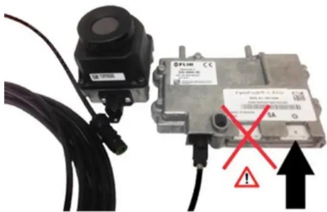
- Connect the power cable to an appropriate, fused 12 volt power supply and connect the other end to the ECU in the port marked with the symbol. The ECU should be grounded to give the best video signal.
NOTE: IT IS VERY IMPORTANT TO CONNECT THE POWER TO THE ECU TO THE INPUT MARKED WITH THE SYMBOL - OTHERWISE YOU MAY DAMAGE THE ECU!
That's it! Congratulations now go enjoy your PathFindIR II!
The ECU is not weatherproof, so it needs to be mounted inside the passenger compartment or in the truck to protect it from moisture. You can either mount it yourself, or use the bracket that comes in the optional Installation kit.
natural_image
Exploded view diagram of an electronic device showing internal components and wiring (no text or symbols)7 Connect the video output cable to the monitor of your choosing. It is recommended that this cable be kept as short as possible.
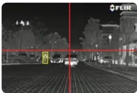
- Once the camera is installed and operating, use the image on the display screen to verify that the camera head is aligned properly.
- In order to get the best Pedestrian and Animal Detection from the unit it needs to be precisely aligned;
- Align the camera so that the center of the image is aligned with the car + or - 2° to the left or right.
- Also make sure the center of the image is level with the horizon + or - 2°.
- Finally, make sure the camera isn't tilted left or right compared to a flat road surface.
- An example of a correct installation is shown below, with example red alignment lines shown:
natural_image
Night street scene with vehicles and a red crosshair overlay, no visible text or symbols
FLIR®
Specifications
PathFindIR II KEY PERFORMANCE
CHARACTERISTICS
Thermal Imager
| Sensor Type 320 x 240 Uncooled Microbolometer |
| Field-of-View 24° (h) x 18° (v) |
| Spectral Band 8-14 microns (LWIR) |
| Outputs NTSC |
Power
| Power Requirements 12 VDC |
| Power Consumption 2 W (6 W w/heater on) 1.8 A max. system current |
Environmental
| Operating Temperature -40°C to 80°C |
| Weather Resistance (Camera) Hermetically Sealed, Automotive Qualified |
| Weather Resistance (ECU) Non-Hermetic; Passenger Compartment mount required |
| Window High-Impact Resistant Optic w/ Built-inAutomatic Heating ElementReplaceable Window |
Physical
| Camera Dimensions | 2.6" × 3.4" × 3.2" (60 × 86 × 82 mm) |
| Camera Weight | 0.6 lb (300 g) |
| ECU Dimensions | 5.8" × 4.3" × 0.9" (148 × 110 × 24 mm) |
| ECU Weight | 0.7 lb (350 g) |
Equipment described herein may require US Government authorization for export purposes. Diversion contrary to US law is prohibited. Specifications are subject to change without notice. For the most up-to-date specs, visit our website: www.flir.com. ©2014 FLIR Systems, Inc. All other brand and product names are trademarks of FLIR Systems, Incorporated. Created 03/24/14

FLIR®
SANTA BARBARA
FLIR Systems Inc
70 Castilian Drive
Goleta, CA 93117
PH: +1 805.964.9797
FAX: +1 805.685.2711
PORTLAND
Corporate Headquarters
FLIR Systems, Inc.
27700 SW Parkway Ave.
Wilsonville, OR 970
PH: +1 866.477.3687
FAX: +1.503.498.3153

Brand : FLIR
Model : PathFindIR II
Category : Uncategorized