
2032 Controller - Lighting Controller MARTIN - Free user manual and instructions
Find the device manual for free 2032 Controller MARTIN in PDF.


| Product Type | Lighting Controller |
| Brand | Martin |
| Model | 2032 Controller |
| Power Supply | 100-240V AC, 50/60Hz (voltage selector switch) |
| Maximum Number of Controllable Units | 32 |
| Memory Capacity | 1000 scenes, 100 sequences, 10 shows |
| Compatible Lighting Units | Roboscan PRO 1220, PRO 218, 1020, 1016, 1004/1005, 804/805; RoboColor; RoboZap; RoboZap MSR 1200; Centrepiece; Martin 516 dimmer controller |
| Trigger Modes | Auto, Manual, Music |
| Package Contents | 1 controller, 1 10m XLR-9 pole DSub cable, 1 terminator plug, 1 program diskette |
| Dimensions | Standard 19" rack mount, 2U height (estimated) |
| Weight | Approx. 5 kg (estimated) |
| Software Version | 1.30 (as per manual) |
| PC Compatibility | Requires 80286 12 MHz or better, 1 MB RAM, 16-bit ISA bus, CGA/EGA/VGA monitor, serial port for mouse |
| Safety Precautions | Never turn off controller while program is running; always exit via Quit Program |
| Programming Levels | Scene, Sequence, Show |
Frequently Asked Questions - 2032 Controller MARTIN
User questions about 2032 Controller MARTIN
0 question about this device. Answer the ones you know or ask your own.
Ask a new question about this device
Download the instructions for your Lighting Controller in PDF format for free! Find your manual 2032 Controller - MARTIN and take your electronic device back in hand. On this page are published all the documents necessary for the use of your device. 2032 Controller by MARTIN.
USER MANUAL 2032 Controller MARTIN
Installing and using 2032 Software, PC version 6
Martin M2032 Controller - Package contents 9
Connecting the controller 9
Getting started 1 1
Configuring the controller 12
Preparing a Data Diskette 14
Before starting to program 14
Programming the controller 15
The Sequence Editor 16
Selecting channels 16
Single channel selection.... 1 6
Selecting a row. 17
The Master channel.... 1 7
Programming the units 17
Programming Sequences 19
Designing a scene 19
Programming a Sequence 19
Deleting a scene 20
Inserting a scene 20
The Reset option 20
Saving a sequence 21
Running a Sequence 22
Follow mode 23
Frozen mode 24
The Online / Offline function 24
The Reset function 24
Deleting a sequence 25
Programming a Show 26
Inserting a Sequence 27
Removing a Sequence 28
Deleting a Show 29
Table Of Contents (Continued)
Running a Show 30
APPENDIX A
32
DIP switch settings for Martin intelligent lighting products 32
DIP switch settings for the RoboColor and Robocolor MSD 200 . . . 33
DIP switch settings for the RoboZap and RoboZap MSR 1200 and the Centrepiece 34
APPENDIX B 35
Programming of specific Martin lighting units 36
Programming Roboscans 36
Programming the RoboZap 39
Programming the RoboZap MSR 1200 4 1
Programming the RoboColor 41
Programming the Centrepiece 46
Programming the Analogue Output 46
Additional Features available for the 2032 Controller 49
Index 54
Preface
To ensure the maximum benefit from the M2032 controller please take time to read this Users Guide before using the controller.
If you are installing some or all of your lamp units together with the controller, read the section about configuring the controller and the sequence editor for some tips about setting the individual address on the units before installation. The DIP switch settings for the various unit types can be found in Appendix A.
For your convenience there is a Glossary and an Index at the back of the manual. Words printed in italics are explained in the Glossary.
Introduction
The Martin 2032 controller is a tool for creating countless numbers of lighting set-ups and provides individual control of up to 32 Martin lighting units.
The current software version supports the following products from Martin Professional:
Roboscan PRO 1220
Roboscan PRO 218
Roboscan 1020
Roboscan 1016
Roboscan 1004/1005
Roboscan 804/805
RoboColor
RoboColor MSD 200
RoboZap
RoboZap MSR 1200
Centrepiece
Martin 516, 16 channel 0-10v. dimmer controller
Future Martin Professional intelligent lighting products will of course be compatible with the 2032 controller with updated software.
The controller has the following memory capacity:
1000 different scenes
Up to 100 different sequences
100 different sequences in each show
10 different shows.
Note: The memory capacity is limited to 1000 different scenes so it can happen that if a particular sequence uses a large number of scenes then you will have to limit the number of scenes in subsequent sequences. There is, however, ample memory to give hours and hours of lighting entertainment. Of course you can program unlimited numbers of scenes, sequences & shows - just use another diskette! The hard disk version of the controller has approximately 10 times the capacity of a diskette.
Installing and using 2032 Software, PC version.
Hardware.
Hardware requirements:
- 80286 12 MHz or better (386Sx,386,486).
- Standard (16 bit ISA) AT bus It will NOT work with a Microchannel bus (most IBM P/S 2 plus a few other brands).
- Minimum 1Mb Ram - 2Mb is preferable as later updates will be based on 2Mb.
- Genius 3 button mouse or compatible (PC-Mouse compatible).
- 1 Serial port for mouse communication. Optional 2nd serial port for external communication (SMPTE, MASTER SLAVE etc. in future updates)
- CGA monochrome or video card and monitor (or EGA, VGA, SVGA color and mono).
Hardware Installation.
Insert the supplied transmitter board in any available slot in the PC. Make sure that the board is firmly seated in the socket. Please refer to the users manual for information concerning connecting the lighting units to the PC.
Software.
Dos versions:
- MS or PCDos Ver 3.3+.
- DRDOS ver 5.0 +.
Floppy Disk Version
To use the floppy disk version - insert the floppy in drive A and boot the computer.
Hard Disk Version
Hard disk version Installation procedure:
If you are installing to a system running on MS-DOS 5.0 please read the special section.
The following requires that you have the Hard disk Installation Diskette (PC version) and are familiar with Dos and PCs.
Installing and using 2032 Software, PC version (Contd.) Hard Disk Version
The system files CONFIG.SYS and AUTOEXEC.BAT files MUST contain at least the following lines.
CONFIG.SYS :
FILES = 20
BUFFERS = 20
DEVICE = VDISK.SYS 360 256 128 /E
The VDISK.SYS is a Virtual disk (Ram disk) device driver. This driver may have different names in different Dos versions. Also the syntax for loading the device driver may change with Dos versions (Eg. Hidevice = etc). The parameters set the size of the virtual disk to 360 Kb, Sector size = 256 Bytes and the max entries in the root directory to 128. The /e parameter indicates that the driver is located in extended memory. If you are installing on top of MS-DOS 5.0 you must also use the HIMEM.SYS driver as memory manager.
Check your manual for the Dos version used. DO NOT copy the driver from the diskette.
AUTOEXEC.BAT :
Gmouse
Roboscan
Gmouse (gmouse.com) is a driver for the mouse. It is found on the Hard disk installation diskette or is supplied with the mouse when you buy it. Different brands have their own drivers and there is no guarantee that other drivers will work.
Now create 10 sub - directories in the root directory named DATA,DATA2,DATA3,...,DATA10.
Copy the following files from the diskette to the Root directory on the hard disk :
ROBOSCAN.EXE
LITT.CHR
CGA.BGI
GMOUSE.COM (If you do not want to use your own driver).
Boot the PC to start the program.
If you don't want the PC to boot with the 2032 software you may create another batch file for starting the program or even start it straight from the command line -just remember to load the mouse driver first.
Installing and using 2032 Software, PC version (Contd.) Hard Disk Version
Important
Please note that the program requires 575Kb of free ram below the 640Kb limit. Use the Dos command CHKDSK to see how much memory there is left after loading the mouse driver.
Installing to MS-DOS 5.0 systems.
The following section includes examples of a CONFIG.SYS and AUTOEXEC.BAT files suitable for use on a MS-DOS 5.0 system.
CONFIG.SYS :
DEVICE=\DOS\HIMEM.SYS DEVICE=\RAMDRIVE.SYS 360 256 128 /E FILES=20 BUFFERS=20
AUTOEXEC.BAT:
PATH=\DOS GMOUSE ROBOSCAN
These two files are minimum requirements for running the program - it even works on a PC with only 1 MB ram. If you wish to use your PC for other things than the Roboscan software you may alter the Config.sys and Autoexec.bat files to suit your needs as long as the virtual disk is set up and the minimum memory requirement is met.
Using the mouse.
When using the mouse you simply duplicate the functions of the conventional trackball and keys. By moving the mouse you move the cursor on the screen as you would using the trackball and the left and right mouse-buttons duplicate the keys on the controller. Some mice have the option of switching between 2 and 3 button operation mode. Please make sure that the mouse operates in 3 button mode.
If you have a mouse connected you do NOT have to click on the Online/Offline field on the screen in order to create a blackout. While in Run sequence or Run Show modes pressing the MIDDLE button on the mouse will toggle between Online and Offline status no matter where the cursor is located on the screen.
Martin M2032 Controller - Package contents
Please make sure you received the following with your M2032 Controller :
1 Martin M2032 Controller.
1 10m XLR - 9 Pole DSub cable.
1 Terminator plug.
1 Diskette with software.
Connecting the controller
Before switching on, ensure that the voltage selector switch is set for your local power supply and if necessary connect a Three pin plug to the mains cable using the Brown wire for the Live connection, the Blue wire for the Neutral connection and the Green/Yellow wire for the Earth (Ground) connection.
WARNING!
NEVER TURN OFF THE CONTROLLER WHILE A PROGRAM IS RUNNING. DOING THIS MAY CAUSE IRREVERSIBLE
DAMAGE TO THE DATA FILES.
ALWAYS EXIT THE PROGRAM VIA
QUIT PROGRAM FROM THE MAIN MENU.

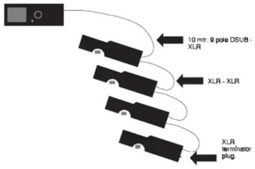
Fig 1. 2032 rear panel Fig 2. Link
flowchart
graph TD
    A["Device"] --> B["Component 1"]
    A --> C["Component 2"]
    A --> D["Component 3"]
    A --> E["Component 4"]
    B --> F["10 mtr. 9 pole DSUB - XLR"]
    C --> G["XLR - XLR"]
    D --> H["XLR terminator plug"]
When connecting the controller use the Dsub-XLR cable to connect the controller to the first unit on the link. Now link up the rest of the units with the XLR-XLR cables that came with the units. Please refer to fig 1 and fig 2. Remember to plug in the terminator-plug that came with the controller into the last unit on the link. If you plan to use the external microphone for music trig, then plug it into the Microphone-jack socket on the rear panel.
Your M2032 controller has the facility to have an extra monitor installed via the Video card on the rear of the controller. The monitor must be a CGA Monitor with RGB Connection. If you are installing units as well as the controller, please read the section about configuration and the section about channel selection before setting the addresses. Also refer to APPENDIX A for setting of DIP switches. Remember - in order to control each unit individually they must have their own individual address.
Getting started
If you are using the diskette version of the controller insert the program diskette you received with the controller in the diskette drive. If you are using the hard disk version make sure that the diskette drive is empty.
Before switching on the controller itself, switch on all the effects you wish to use with the controller. This is to prevent start-up noise from the units from interfering with the controller. After a minute or so, start the controller by turning the key or pressing the power switch, depending on the controller model.
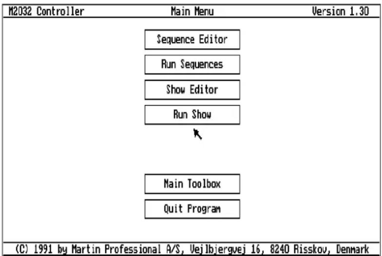
Fig 3. Main menu
After a short self-test the controller will load the software from the diskette or hard disk, and after a short initialisation the controller will be ready displaying the 'Main Menu' on the screen (Fig 3).
You can now use the trackball to move the arrow so that it points at the box or field that you want to select. You then press the left button to select or click the function. Unless you are specifically asked to click the right button you can assume that the left button is to be used.
Configuring the controller
Before using the controller you must specify which type of units the controller is supposed to control. This is done by selecting the Main Toolbox from the Main Menu. If you are using the hard disk version it will look like fig 4. If you are using the floppy disk version the screen will contain the two options Change Data diskette and Prepare New Data diskette whilst Change Data library is present in the hard disk version only.

flowchart
graph TD
    A["Delete Sequences"] --> B["Change Data library"]
    B --> C["Configuration"]
    C --> D["Quit Main Toolbox"]
Fig 4. Main Toolbox
From the Main Toolbox, select Configuration to get to the configuration screen.

Fig 5. Configuring the controller
Configuring the Controller (Continued)
To configure a channel for a specific unit (e.g. Roboscan 1004 or RoboZap) simply move the selection bar to the channel with the number corresponding to the address set on the unit. Then press the left button to get a list of supported units (fig 5). Use the trackball or mouse to scroll the selection bar over the desired unit and select the unit by pressing the left button. Please note, all units currently supported by the M2032 only take up one channel, except the Roboscan 1020 and Roboscan PRO 1220 which take up two combined channels.
| M2032 Controller Channel Configuration Version 1.30 | |||||
| Channel | Symbol | Configuration | Channel | Symbol | Configuration |
| 1 | 1005 | Roboscan 804/5-1004/5 | 17 | 1020 | Roboscan 1020 A |
| 2 | 1005 | Roboscan 804/5-1004/5 | 18 | 1020 | Roboscan 1020 B |
| 3 | 1005 | Roboscan 804/5-1004/5 | 19 | 1020 | Roboscan 1020 A |
| 4 | 1005 | Roboscan 804/5-1004/5 | 20 | 1020 | Roboscan 1020 B |
| 5 | 1005 | Roboscan 804/5-1004/5 | 21 | 1020 | Roboscan 1020 A |
| 6 | 1005 | Roboscan 804/5-1004/5 | 22 | 1020 | Roboscan 1020 B |
| 7 | 1005 | Roboscan 804/5-1004/5 | 23 | 1020 | Roboscan 1020 A |
| 8 | 1005 | Roboscan 804/5-1004/5 | 24 | 1020 | Roboscan 1020 B |
| 9 | 1016 | Roboscan 1016 | 25 | Zap | RoboZap |
| 10 | 1016 | Roboscan 1016 | 26 | Zap | RoboZap |
| 11 | 1016 | Roboscan 1016 | 27 | Zap | RoboZap |
| 12 | 1016 | Roboscan 1016 | 28 | Zap | RoboZap |
| 13 | 1020 | Roboscan 1020 A | 29 | Col | RoboColor |
| 14 | 1020 | Roboscan 1020 B | 30 | Col | RoboColor |
| 15 | 1020 | Roboscan 1020 A | 31 | AN | Analogue Output |
| 16 | 1020 | Roboscan 1020 B | 32 | AN | Analogue Output |
Fig. 6 Configuration
When you have configured the controller to match your units, press the right button to exit from the configuration screen back to Main Toolbox. The controller will save the configuration to diskette or hard disk and use it as default when turned on. If you later decide to change or add more units to the controller simply use Configuration to configure the controller to match your new configuration. Select Quit Main Toolbox to return to the Main Menu.
Preparing a Data Diskette
If you are working with the floppy diskette version the best thing you can do is to make one or more data diskettes in addition to the program diskette. To make a data diskette all you need is a standard 3 1/2" 720 KB diskette, available in any computer store.
DO NOT TRY TO MAKE A DATA DISKETTE WITH THE PROGRAM DISKETTE THAT CAME WITH THE CONTROLLER.
Before using the diskette however it must be prepared (formatted) and tested. To do this insert your program diskette. Select 'Prepare new Data diskette' from the 'Main Toolbox' and follow the on-screen prompts. Be sure to remove the program diskette when you are told to. Do not remove any diskettes from the drive unless you are prompted to. If the diskette has any errors the program will tell you so and refuse to use it. Once you have prepared the data diskette you should not repeat the process with that same diskette because formatting completely erases all data on the diskette used. To use any data diskette (including the program itself) select Change Data diskette from Main Toolbox and insert the data diskette (which MUST have been prepared) when prompted to.
Do not change the diskette without using the Change Data diskette option as this will cause damage to your datafiles.
Before starting to program
We are now ready to start programming the controller. If you are unfamiliar with the different Martin lighting units which you possess please refer to Appendix B which contains detailed descriptions of all of the Martin unit types which the M2032 can control.
Programming the controller
When programming the units on the controller, there are three levels of programs :
Scene, Sequence and Show.

flowchart
graph TD
    A["Show"] --> B["Sequence"]
    B --> C["Scene"]
    A --> B
    A --> C
    B --> C
Fig 7. Scenes - sequences - shows
As seen in fig 7 the Scene represents the simplest possible element in a program. It consists of one setting per function for each of the units.
A sequence is one or more related scenes that the controller will execute in sequential order. The effects are obtained when color, gobo, movement etc. are changed from one scene to the next.
Later when you have written a number of sequences you may link any of these sequences together to create a show.
In other words:
A show contains information about sequences that contain information about scenes which in turn contain information about the settings of each function of each lighting unit.
The Sequence Editor
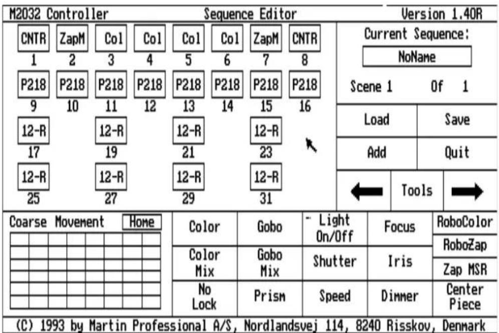
Fig 8. Sequence Editor
The Sequence Editor is where you write the programs for your units. Enter the editor by selecting Sequence Editor from the Main Menu. As you can see the channels you have configured are represented on the screen by squares containing the symbols of the configured units, as seen in Fig.8. This screen is primarily used to program Martin Roboscans and selecting different types of programming tools. All the other unit types have their own editing screens.
Selecting channels
Before programming your units you must specify the units you wish to program. Do this by selecting one or more channels.
Single channel selection.
To select a single channel for programming, click with the left button on the field representing the channel. The channel will now be highlighted and is selected for programming. You may click on several or all channels to enable them all for programming. Clicking a second time on the channel de-selects the channel. In shortclicking on a channel will toggle the status (selected/not selected) of that channel.
An exception is the analog unit. The programming of this unit will be separately dealt with later in its own section.
The Sequence Editor (Continued)
Selecting a row.
If you use the right button for the selection, all the channels in that row are now set to the status of the channel you are currently selecting.
Using this feature can save you a great deal of time when programming. Often you will want to program the same feature for several different units, and it is so much easier to select all 8 units on a row in one selection, than selecting 8 individual units one by one. Thus the best way to configure your controller is to put similar units (eg. Roboscans) on the same row for fast selection.
The Master channel.
When you select a channel you will see an extra frame around that channel. This means that this channel is now the Master channel. If you have selected other channels that control units of the same type as the Master channel (eg. Roboscans), these units will be programmed with the same values as you program the Master channel. In this way you may program the same features, such as color, gobo, tilt etc., for several units at the same time. Please note that at all times a Master Channel must be selected to enable programming of the units.
Programming the units
Each type of lighting unit has its own method of programming which is described in Appendix B.
Common to all unit types is that you need to select the channels you wish to program and then select the function you wish to use by clicking on the field of the function you need.
Not all units support all the features shown on the editor screen (eg. focus or dimmer). Attempting to program units with features that are not available does no harm - the program just ignores it!
While new and innovative products from Martin Professional come onto the lighting market regularly, each of them has its own specific market and has been produced after many painstaking hours of research and development. One such case is the new Roboscan PRO 1220 which, aimed at the touring market, has many specially designed features. The most important of which is the facility to be able to remotely turn the electricity supply on or off to the lamp, thus saving lamp life when it is not being used.
When first turning on the unit the lamp will not fire up - you need the controller to turn the lamp on. To turn the lamp on and start programming or running your sequences you must first follow the instructions laid out below :
After booting up the controller you will find yourself at the 'Main Menu', (see fig.3), click on the field marked 'Sequence Editor' and you will see a screen as in fig.8. On this screen you will see a field marked 'Tools', click on this field and a screen as in fig.11 will appear as a sub-page. You will see that there are Two boxes - one marked 'Lamp On' and one marked 'Lamp Off'. These are the Two controls for turning the lamp on and off on the PRO 1220 ONLY. By clicking on the field marked 'Lamp On' the lamp will fire and by clicking on the field marked 'Lamp Off' the lamp will be turned off. These two features can be used in sequences that you write but they should be the only command given to the unit E.G. no color or gobo changes aswell. Please note that because the Roboscan PRO 1220 uses a discharge lamp YOU WILL NEED TO WAIT AT LEAST TEN MINUTES AFTER YOU HAVE SWITCHED THE LAMP OFF BEFORE YOU CAN SWITCH IT BACK ON AGAIN SUCCESSFULLY.
Programming Sequences
Designing a scene
Design your own scene by clicking the channel number(s) and adjusting the functions of the units you want to use. Refer to Appendix B at the back of this manual about each particular type of unit. Remember that you can program 2 or more similar units at the same time if you want them to perform the same functions. When you are satisfied with your creation click the Add field with the left button.
Programming a Sequence
When you clicked the Add field the screen remained unchanged except that we are now in scene 2 Of 2. The units remain in their settings for scene 1. You have, in fact, programmed the first scene in a sequence and stored it in the memory. Scene 2 is, at the moment, exactly the same as Scene 1 and it is also stored in the memory. You can now edit Scene 2. If you want to return to scene 1 just click the left arrow with the left button. You can now make changes to scene 1. As soon as you have changed a setting in Scene 1 it is stored in the memory. To return to Scene 2 use the arrow keys. Do not use Add at this stage because if you do, your new settings for scene 1 will be stored as a new scene at the end of the sequence - in this case as Scene 3. If you don't make any changes then you can click the right arrow to proceed to Scene 2 without changing Scene 1.
You can now program scene 2 and then Add it.
You can click the arrow fields to step forwards and backwards through the sequence and you are free to change the settings of any scene at any time - just remember you must use the arrow fields to proceed to the next scene or to return to the previous scene. If you use Add at this stage your new setting will be regarded as a new scene to be added at the end of the sequence. Clicking the Add field can be used to Add one or more repeats of the current scene to the end of the sequence. Every time you click Add, the sequence becomes one scene longer. It is important to understand the difference between the Add field and the arrow fields.
(If you have previously Saved the sequence - see below - then you can always return to the old version if you regret the changes you have made. Just click Quit and then the Cancel Save option from the keyboard screen).
Deleting a scene
To delete a scene click the 'Tools' field on the 'Sequence Editor' screen. The screen shown in fig. 11 will appear.
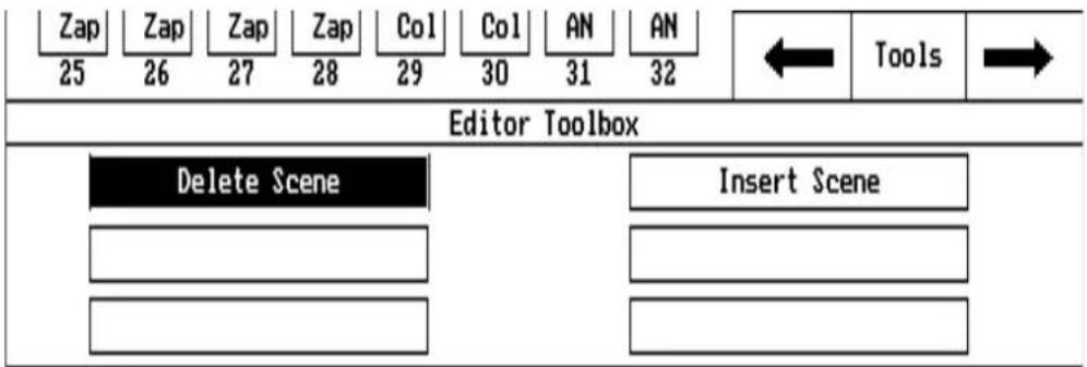
Fig 11. Editor tools
Use the trackball to highlight the 'Delete Scene' field and press the left button. The screen prompts you to push the right button if you really mean it, or the left button to return to the previous screen. Pushing the right button now deletes the scene. Push the right button again to return to the Sequence Editor screen.
Inserting a scene
To insert a scene click the arrow fields to move to the scene just BEFORE the point you want to insert a new scene. Click the ‘Tools’ field on the Sequence Editor screen. The screen shown in fig 11 appears. Use the trackball to highlight the Insert Scene field and press the left button. The screen prompts you to push the right button if you really mean it, or the left button to return to the previous screen. If you push the right button you insert the scene. Push the right button again and you are back to the Sequence Editor screen and can now edit the scene which you have inserted.
The Reset option
Clicking the Reset field on the Sequence Editor screen, resets all the (selected) units to their default settings and you will hear the mirrors, color wheels, gobo wheels etc. move to their neutral positions.
Saving a sequence
When you are satisfied with your sequence, click 'Save' with the left button. The keyboard screen (fig 13) will appear. This shows that the name of the sequence is NoName. You must give the sequence a new name with up to 15 letters or numbers. It's a good idea to give the sequence a descriptive name to make it easier to find later. To "type" in a name first click six times on the BS (backspace) button. Each click erases one letter. You can now use the trackball to point at the letters and use the left button to enter them. Let's call the first sequence SEQ1 - very original! Now click the Save field and the sequence will be stored on the disk. If you want to return to the Main Menu without saving your sequence just click Cancel Save instead and you will return to the Sequence Editor screen. If you try to save a sequence which has the same name as a sequence which is already on the disk you will be asked if you want to overwrite the other sequence. If you click the Yes button the old version will be lost. If you click the No button the keyboard will reappear and you can change the name.

Fig. 13 Keyboard
You can now program another sequence. There is enough memory for up to 100 different sequences. Remember there is only enough memory for 1000 different scenes in all, so if your sequences use a large number of different scenes you may not have enough memory for 100 sequences.
If you don't want to program another sequence click the Quit field to return to the Main Menu.
Programming Sequences (Continued)
Editing a Sequence
If you want to edit a sequence which you have programmed click the Sequence Editor field on the Main Menu and then click the Load field on the Sequence Editor screen. Move the highlight bar to the required sequence and press the left button. Clicking the 2 arrow fields you can step through the sequence until you get to the scene you want to change. You must click on the channel(s) and they will be highlighted. You can now make changes to the scene. To save your changes you must Click one of the arrow keys. If you use the Add field your new settings will be added as a new Scene to the end of the Sequence.
Running Sequences
Running a Sequence
| M2032 Controller Run Sequences Version 1.30 | |||||||||
| 1005 1 1016 9 1020 17 Zap 25 | 1005 2 1016 10 1020 17 Zap 26 | 1005 3 1016 11 1020 19 Zap 27 | 1005 4 1016 12 1020 21 Zap 28 | 1005 5 1020 13 1020 21 Col 29 | 1005 6 1020 15 1020 23 Col 30 | 1005 7 1020 AN 31 | 1005 8 1020 23 AN 32 | Current Sequence: Scene Of Trig Rate : 1.00 Sec. - Run mode - Follow mode - Frozen | |
| Follow Functions | Trig Pad | Auto Trig | Music Trig | Load | Reset | ||||
| Iris | Shutt. | Color Mix | Color | Pan/Tilt | |||||
| Focus | Dimmer | Gobo Mix | Gobo | On/Off | Manual Trig | Trig Delay | Quit | ||
| (C) 1991 by Martin Professional A/S, Uejlbjergvej 16, 8240 Risskov, Denmark | |||||||||
Fig 14. Running a Sequence
To run a sequence click 'Run Sequences' from the Main Menu and the Run Sequences screen appears (fig 14).
Click the Load field with the left button and you will see a list of the pre-programmed sequences (fig 15). Use the trackball to move the bar up or down until it is placed over the sequence you want to run. If there are more than 10 sequences you can use the Up and Down fields to go to the next or previous "page". When you have highlighted the sequence press the left button. The name of the sequence appears in the 'Current Sequence' field and the sequence immediately begins to run. If you move the trackball and click on another sequence then this sequence will take over and immediately start to run.
Running Sequences (Continued)

other
Run Sequences | | Run Sequence | Sequence | Scenes | Auto | |---|---|---|---|---| | 101 | Up | N | 2.1.00 | | | 11 | N | SEQ1 | 5.1.00 | | | 102 | N | SEQ2 | 15.1.00 | | | 19 | N | SEQ3 | 11.1.00 | | | 2a | | | | | | 27 | | | | | | NF | | | | | | lor | | | | | | ix | | | | | | Down | | | | | | Xho | | | | | | Ix | | | | | | Martin Professional A/S, Vejlbjergue, 16,8 Auto Trig Manual TrigFig 15. Loading a Sequence
Note that the Auto Trig field is highlighted and that the Trig Rate is 1.00 second. This means that the internal metronome is triggering the Sequence at the default rate i.e.the Sequence steps to a new Scene every second. If you want to change this Trig Rate or any of the other functions you must click the right button to return to the Run Sequences screen. To change the Trig Rate just click the Trig Pad two or more times. The period of time between two clicks decides the rate at which the controller steps through the sequence - from fractions of a second up to 999 seconds. When you quit the Run Sequences screen this Trig Rate will be stored on the diskette.
You can also click Auto Trig to disable the metronome and click Manual Trig instead. Now the scene only changes when you click the Trig Pad. You can also highlight both Auto Trig and Manual Trig at the same time. The sequence will then change at the metronome rate but if you click the trig Pad the sequence will immediately move to the next scene as well. When Manual Trig is highlighted you can't change the Auto Trig Rate.
Another method of triggering the sequence is to use a music signal from a sound source. The sequence will be triggered by the peaks in the music - usually the snare or bass drum. If the music stops, the sequence stops changing.
If both Auto Trig and Music Trig are highlighted the sequence will change at the metronome rate but will also be triggered by peaks in the music.
Sometimes the music or other sounds picked up by the sound source cause the Sequence to trigger too fast. In this case the Trig Delay function can be used to set a minimum time between the next steps. Click the Trig Delay field and use the trackball to select a delay time. This delay can be set from 1 to 20 tenths of a second.
These alternative Trig methods are not stored when you quit the Run Sequences screen -a sequence always starts in Auto Trig mode.
Follow mode
While a sequence is running you can over-ride the programmed scenes and take over control of Roboscan units. Clicking a channel field causes that field to be highlighted and the unit remains in its current position and ceases to respond to the sequence programming. None of the other units are affected. By clicking the relevant field you can change the functions in the same way as when designing a scene so you can use the Roboscan as a follow-spot or change all the programmable functions. You can put as many Roboscans in Follow Mode as you want to but they will all perform the same follow-functions. By then clicking a channel field twice with the left button returns the unit to the sequence program.
Running Sequences (Continued)
Frozen mode
If you click a channel field twice with the left button you will "freeze" the unit in its current position and with the current setting of the functions. It will remain here until you click the channel field once, when it will return to the sequence program.
Please Note that Frozen Mode and Follow Mode have no effect on RoboColor, RoboZap and Analog units.
The Online / Offline function
When you first enter the Run Sequences page this field is in the ONLINE state and the sequences will run normally. When you click this field the status becomes OFFLINE and all the units will blackout and return to the their factory neutral settings. Clicking the field again returns the status to ONLINE and the sequence will continue running from the point where it was interrupted. When you are in the OFFLINE state you can still load a new sequence and/or change the settings of the TRIG RATE Etc.
The Reset function
Clicking the ‘Reset’ field when none of the units are in Follow mode runs the reset routine and sets all the units to their default settings (the settings they have when they are switched on) and exits from the sequence. If you are running a sequence when you click Reset this sequence will no longer be displayed in the Current Sequence window but it is still on the disk.
If one or more units are in Follow mode only these units will be reset - all the others will continue to run the sequence. This is useful if you need to switch off some of the units without stopping the sequence. If you click the channel field twice the unit will return to the sequence. In some cases it may be necessary to turn on the lamp after using reset (you can do this in Follow mode).
To return to the Main Menu click on the 'Quit' field.
Deleting a sequence
To delete a sequence return to the Main Menu and select the Main Toolbox field, then select the Delete Sequence field and the screen shown in fig 16 will appear.
The Prev. and Next boxes refer to the next and previous "pages" of sequence names. Click the name field of the sequence you want to delete and then click delete. You will be asked if you really mean it and answer yes with the right button or no with the left.
If you need to delete more than one sequence you can highlight all the unwanted sequences at the same time and then one click on the right button deletes them all. If you have used the sequence in one or more shows you cannot delete it until you have deleted it from all shows. (See "Removing a sequence" in the "Programming a show" section).
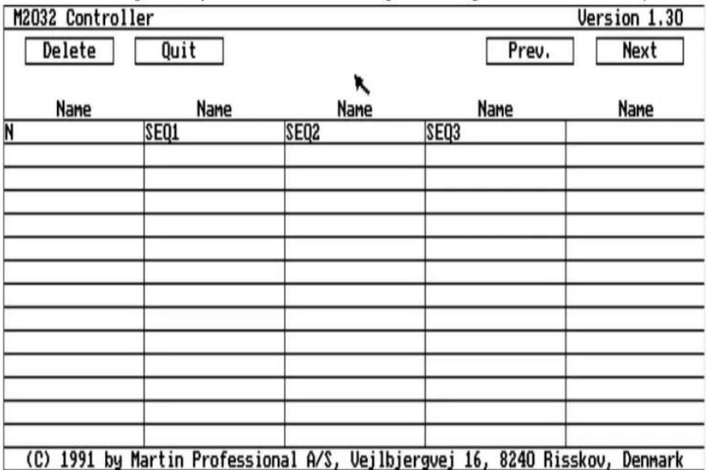
Fig 16. Deleting a Sequence
Programming a Show
Lets assume that you have programmed a few sequences, say SEQ1, SEQ2, SEQ3 and SEQ4 and you would like to put together a show using these sequences. You could manually run through the sequences one by one but the advanced features of the 2032 allow you to program a complete show.
From the Sequence Editor screen click Quit with the left button after you have saved the last sequence. This returns you to the Main Menu. Now select the Show Editor field and then select the Create New Show field and the screen shown in figure 17 will appear.

Fig 17. Edit a Show
Click 'Add Sequence' and a list of available sequences can be seen. Choose one of these, let's start with SEQ1. The chosen sequence's name appears in the large field as shown in fig 18.

Fig 18. Sequence information
Programming a Show (Continued)
The information tells us that there are 5 scenes in this sequence and that the (Auto) trig rate is 1 second. If you want to change the contents of the sequence you have to go back to the Sequence Editor and re-program the sequence and if you want to change the auto rate - re-program it in the Run Sequences mode. We can also see that the trig method is Auto Trig.
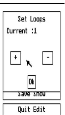
You can decide how many times this sequence is to be repeated by changing the setting of the Loop function. To do this click 'Sequence Loops' and the sequence in question will be highlighted. Click again and the screen shown in fig 19 appears and you can click the + and - fields to set the number of repetitions. When you're satisfied, click 'Ok'.
Fig 19. Loops
Inserting a Sequence
You can also add a sequence between two already programmed sequences by clicking 'Insert Sequence' and then positioning the highlight bar on the sequence below the point you want to insert. Clicking the left button will produce the screen shown in fig 20 and clicking the right button will complete the insertion.

Fig 20. Inserting a sequence
Removing a Sequence
In a similar way you can remove a sequence by clicking the 'Remove Sequence' field and positioning the highlight bar. Clicking the left button brings up Fig 21 and clicking the right button removes the sequence. The sequences disappear from the show but are still available in memory. If you want to remove them permanently you must use the Delete sequence option which you can reach from the Main Toolbox, via the Main Menu.

Fig 21. Removing a Sequence
In this way you can select sequences and loop numbers and program and edit a complete show. When you have finished click Save Show and the keyboard appears. You can give the show a name using the same procedure as when you named the sequences.
Pre-programming the Trig mode
When you are in the Edit Show mode you may select a trig mode for each of the sequences in the show. To do this you must first select the Select Trig field. Now move the selection bar over the sequence you want to set and press the left button. You may now select between Auto and Music trig for this sequence. Move the selection bar over the desired trig mode and press the left button again. If you have changed the trig mode, you will see it indicated in the sequence list in the window on the left hand side of the screen. The sequences can now be set to run to these separate Trigs when you enter the Run Show mode of the controller. See the section of the manual called 'Selecting a Trig Mode in Run Show'.
You can now select the ‘Quit Edit’ field and then the ‘Quit Sow Editor’ field to return to the Main Menu.
Programming a Show (Continued)
Deleting a Show
To delete a show select the Show Editor field from the main menu and select the Delete Show field. A list of shows appears and you select one and click the left button. You will be asked to confirm this decision by clicking the right button. Pushing the left button returns you to the previous screen.
Running a Show
Now you can run your show! Just click the Run Show Field and the screen shown in fig 22 will be seen. Note that the screen shows that the Sequence Mode is manual (see below for an explanation of this). You can change the sequence mode either before or after loading a show.
To load a show, click the Load Show field, select a show from the list and click again and the chosen show will immediately start running. You can see on the screen which sequence is running and all the data for the sequence is also displayed: how many scenes, the trig mode, the autorate, Time Out times and the number of loops.

Fig 22. Running a Show
The Sequence Mode field has Three different modes which can be selected in turn by clicking.
Manual Mode: Clicking 'Next Seq.' or 'Prev.Seq.' causes instant jumping to the next or previous sequence. Use the right button to cancel this function.
Loop mode: The show repeats each sequence the number of times displayed in the Loop column. You may still jump to next or previous sequence by clicking Next Seq. or Previous Seq.
Time Out mode:
The show runs each sequence for a period of time shown in the Time Out column. This time period can be set for each sequence by Clicking the 'Time Out' field. The Time Out period is the time between 2 consecutive clicks of the left button. After the second click the highlighting bar moves on to the next sequence and the timeout setting for this sequence has started. One click marks the length of this period and then we have moved to the next sequence. In this way you can set TimeOut periods for all the sequences in the show. When you click on the last sequence the highlighting bar automatically returns to the first sequence and you can repeat or correct your settings. If you are satisfied with the settings push the right button. If you are in the Time Out mode the show will now start to run, the sequences changing according to the Time Out periods.
Selecting a Trig Mode in Run Show
There are Three different types of Trig rate used in the Run Show mode and by clicking on the field marked 'Trig Mode' the controller will cycle through the Three options that are available :
Auto Trig Mode : When the field displays ‘Auto Trig’, all sequences in the show will run at the Auto Trig rate which you set in the ‘Run Sequences’ mode.
Music Trig Mode: When the field displays ‘Music Trig’, all sequences in the show will be triggered by the external music source that connects into the rear of the controller.
Program Mode : When the field displays ‘Program’, all sequences will be triggered from the source that was given to them in the ‘Show Editor’ mode when the show was created. E.G. some sequences will have an Auto trig and some will have a Music trig.
Loading another show while already running a show results in the new show immediately taking over in the same sequence mode as the first show.
APPENDIX A
DIP switch settings for Martin intelligent lighting products
DIP switch settings for the Roboscan 804/5,1004/5,1016 and PRO 218
| Address settings for the Roboscan 804/5,1004/5,1016 and PRO 218 | |||
| Unit no. Unit no. | |||
| 1 | 1 | 17 | 1,5 |
| 2 | 2 | 18 | 2,5 |
| 3 | 1,2 | 19 | 1,2,5 |
| 4 | 3 | 20 | 3,5 |
| 5 | 1,3 | 21 | 1,3,5 |
| 6 | 2,3 | 22 | 2,3,5 |
| 7 | 1,2,3 | 23 | 1,2,3,5 |
| 8 | 4 | 24 | 4,5 |
| 9 | 1,4 | 25 | 1,4,5 |
| 10 | 2,4 | 26 | 2,4,5 |
| 11 | 1,2,4 | 27 | 1,2,4,5 |
| 12 | 3,4 | 28 | 3,4,5 |
| 13 | 1,3,4 | 29 | 1,3,4,5 |
| 14 | 2,3,4 | 30 | 2,3,4,5 |
| 15 | 1,2,3,4 | 31 | 1,2,3,4,5 |
| 16 | 5 | 32 | 6 |
| Sequence settings for the Roboscan 804/5,1004/5,1016 and PRO 218 | |
| Description | |
| Test | All switches set to OFF position |
| Demo 1 | 2,6 |
| Demo 1, with music trig | 1,2,6 |
| Demo 2 | 3,6 |
| Demo 2, with music trig | 1,3,6 |
| Demo Random wide angle | 2,3,6 |
| Demo Random wide angle, with music trig | 1,2,3,6 |
| Demo Random narrow angle | 4,6 |
| Demo Random narrow angle, with music trig | 1,4,6 |
| Mechanical stop (For service use) | 1,3,4,5,6 |
| Adjustment (For service use) | 3,4,5,6 |
| Led chase (For service use) | 2,4,5,6 |
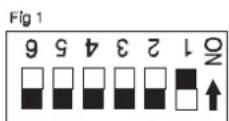

This appendix shows the different address and sequence settings for the DIP switch on the Roboscan models 804/5,1004/5,1016 and PRO 218.
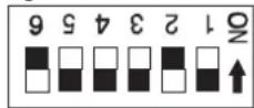
The above settings refer to the pin(s) on the DIP switch which are set to the ON position.
The examples in figure 1 and figure 2, would be described above as; "1"(Unit no.1), and; "2,6"(Demo 1).
DIP switch settings for the Roboscan 1020 and PRO 1220
| Address settings for the Roboscan 1020 and PRO 1220 | |||||
| Unit no. S | Section A Section B | Unit no. Section A S | Section B | ||
| 1 | 1 | 2 | 9 | 1,5 | 2,5 |
| 2 | 1,2 | 3 | 10 | 1,2,5 | 3,5 |
| 3 | 1,3 | 2,3 | 11 | 1,3,5 | 2,3,5 |
| 4 | 1,2,3 | 4 | 12 | 1,2,3,5 | 4,5 |
| 5 | 1,4 | 2,4 | 13 | 1,4,5 | 2,4,5 |
| 6 | 1,2,4 | 3,4 | 14 | 1,2,4,5 | 3,4,5 |
| 7 | 1,3,4 | 2,3,4 | 15 | 1,3,4,5 | 2,3,4,5 |
| 8 | 1,2,3,4 | 5 | 16 | 1,2,3,4,5 | 6 |
| Sequence settings for the Roboscan 1020 and PRO 1220 | |
| Description Section A and B use the same settings | |
| Test | All switches set to OFF position |
| Demo | 2,6 |
| Demo random 1 | 2,3,6 |
| Demo random 2 | 4,6 |
| Mechanical stop (For service use) | 1,3,4,5,6 |
| Adjustment (For Service use) | 3,4,5,6 |
| Led chase (For Service use) | 2,4,5,6 |


This appendix shows the different address and sequence settings for the DIP switches in section A and B on the Roboscan 1020 and PRO 1220.
The above settings refer to the pin(s) on the DIP switch which are set to the ON position.
The examples in figure 1 and figure 2, would be described above as;"1"(Unit no.1, Section A). and; "2,6"(Demo (Either section)).
| Address settings for the RoboColor and Robocolor MSD 200 | |||
| Unit no. Unit no. | |||
| 1 | 1 | 17 | 1,5 |
| 2 | 2 | 18 | 2,5 |
| 3 | 1,2 | 19 | 1,2,5 |
| 4 | 3 | 20 | 3,5 |
| 5 | 1,3 | 21 | 1,3,5 |
| 6 | 2,3 | 22 | 2,3,5 |
| 7 | 1,2,3 | 23 | 1,2,3,5 |
| 8 | 4 | 24 | 4,5 |
| 9 | 1,4 | 25 | 1,4,5 |
| 10 | 2,4 | 26 | 2,4,5 |
| 11 | 1,2,4 | 27 | 1,2,4,5 |
| 12 | 3,4 | 28 | 3,4,5 |
| 13 | 1,3,4 | 29 | 1,3,4,5 |
| 14 | 2,3,4 | 30 | 2,3,4,5 |
| 15 | 1,2,3,4 | 31 | 1,2,3,4,5 |
| 16 | 5 | 32 | 6 |
| Sequence settings for the RoboColor and Robocolor MSD 200 | |||
| Description | |||
| Test | All switches set to OFF position | ||
| Demo 1 | 2,6 | ||
| Demo 1, with music trig | 1,2,6 | ||
| Demo 2 | 3,6 | ||
| Demo 2, with music trig | 1,3,6 | ||
| Demo random wide angle | 2,3,6 | ||
| Demo random wide angle, with music trig | 1,2,3,6 | ||
| Demo random narrow angle | 4,6 | ||
| Demo random narrow angle, with music trig | 1,4,6 | ||
| Pre-program chase | 2,4,6 | ||
| Pre-program chase, with music trig | 1,2,4,6 | ||
| Mechanical stop (For service use) | 1,3,4,5,6 | ||
| Adjustment (For service use) | 3,4,5,6 | ||
| Led chase (For service use) | 2,4,5,6 | ||


This appendix shows the different address and sequence settings for the DIP switch on the RoboColor and Robocolor MSD 200.
The above settings refer to the pin(s) on the DIP switch which are set to the ON position.
The examples in figure 1 and figure 2, would be described above as; "1" (Unit no.1). and; "2,6"(Demo 1).
DIP switch settings for the RoboZap and RoboZap MSR 1200 and the Centrepiece
| Address settings for the RoboZap and RoboZap MSR 1200 and the Centrepiece | |||
| Unit no. Unit no. | |||
| 1 | 1 | 17 | 1,5 |
| 2 | 2 | 18 | 2,5 |
| 3 | 1,2 | 19 | 1,2,5 |
| 4 | 3 | 20 | 3,5 |
| 5 | 1,3 | 21 | 1,3,5 |
| 6 | 2,3 | 22 | 2,3,5 |
| 7 | 1,2,3 | 23 | 1,2,3,5 |
| 8 | 4 | 24 | 4,5 |
| 9 | 1,4 | 25 | 1,4,5 |
| 10 | 2,4 | 26 | 2,4,5 |
| 11 | 1,2,4 | 27 | 1,2,4,5 |
| 12 | 3,4 | 28 | 3,4,5 |
| 13 | 1,3,4 | 29 | 1,3,4,5 |
| 14 | 2,3,4 | 30 | 2,3,4,5 |
| 15 | 1,2,3,4 | 31 | 1,2,3,4,5 |
| 16 | 5 | 32 | 6 |
| Sequence settings for the RoboZap and RoboZap MSR 1200 and the Centrepiece | |
| Description | |
| Demo 1 | 2,6 |
| Demo 1, with music trig | 1,2,6 |
| Demo 2 | 3,6 |
| Demo 2, with music trig | 1,3,6 |
| Demo random wide angle | 2,3,6 |
| Demo random wide angle, with music trig | 1,2,3,6 |
| Demo random narrow angle | 4,6 |
| Demo random narrow angle, with music trig | 1,4,6 |
| Pre-program chase | 2,4,6 |
| Pre-program chase, with music trig | 1,2,4,6 |
| Rotation ramp | 3,4,6 |
| Rotation ramp, with music trig | 1,3,4,6 |
| Mechanical stop (For service use) | 1,3,4,5,6 |
| Adjustment (For service use) | 3,4,5,6 |
| Led chase (For service use) | 2,4,5,6 |
Fig 1
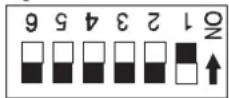
Fig 2
This appendix shows the different address and sequence settings for the DIP switch on the RoboZap and RoboZap MSR 1200 and the Centrepiece.
The above settings refer to the pin(s) on the DIP switch which are set to the ON position.
The examples in figure 1 and figure 2, would be described above as;"1"(Unit no.1). and; "2,6" (Demo 1).
APPENDIX B
Programming of specific Martin lighting units
Programming Roboscans
The following functions are available when programming Roboscans. If you are not sure if your Roboscans support the functions just try them out. Remember to select the channel(s) before selecting the function. Common to most functions is that you exit them with the right button.
Functions:
Lamp On/Off This will toggle the lamp on or off.
Movement To move the mirror of the Roboscan select Movement by clicking on the grid in the bottom left of the screen.Now if you move your trackball (or mouse) the round lamp symbol in the grid moves and so will the mirror of your selected Roboscan(s). When you enter the movement function, the default setting of the movement resolution is 'coarse'. To obtain a much finer resolution press the left button once. Press the left button again to return to coarse mode. The resolution mode has nothing to with the speed at which the mirrors will move when your program is running, it is just a help when positioning. When you are satisfied with the position press the right button to exit the movement function. Note that when programming a Roboscan with microstepping motors, the fine movement makes it possible to position the light with extreme precision.
Home The Home function, located just above the movement grid moves the mirror so fall the selected Roboscans to the neutral position, which is centred in pan and tilt.
Lock Selecting this function will lock (or unlock) one of the movement directions of the mirror. Select this function repeatedly to go through Pan-Lock, Tilt-Lock and No-Lock. This function is very useful if you need your Roboscans to move in parallel lines.
Color When you select the Color function, two columns appear on the right side of the screen. By moving the scroll bar up and down the color of the Roboscan will change within the limitations of the model type. The right column is for the Roboscans equipped with two color wheels. Simply move the trackball to the right to select color for the second, and to the left for the first wheel. When you are satisfied with the color press the right button to exit the function.
Gobo This function works just like the Color function except that it provides different gobo patterns instead of colors.
Programming Roboscans (Continued)
Rotating Gobos This function can only be used when you have PRO 1220-IIR units configured into your controller. When you select 'Gobo' you will see that the Right hand column of the sub screen is different from a PRO 1220-I, there are Four gobos marked, a line reading 'STOP', and then the speed controls. Move the trackball to this Right hand column. To select a rotating gobo you must position the scroll bar on top of the required gobo and then press the left button on the controller. The gobo will not change until you press the left button. To make the gobo rotate, move the scroll bar to the line marked 'STOP' and press the left button, the display will change to 'CW', for clock-wise, and the gobo will rotate. Press the left button again and the display will change to 'CCW', for counter clock-wise, and the gobo will rotate in the opposite direction. To control the speed at which the gobo rotates move the scroll bar to the lines for speed and adjust the speed accordingly up and down. When you are satisfied with the effect press the right button to exit the function.
Color Mix When you select this function you will see two horizontal slide-bars at the bottom of the screen. When you move the trackball or mouse from side to side a marker will follow the movement. If your Roboscans are capable of color mixing the color wheel will now move in very small steps making it possible to mix two adjacent colors. Note that different Roboscans have their different' active' area on the slide-bar. The lower slide-bar is for the second Color-wheel on Roboscans with two color wheels. To shift between the two wheels move the trackball or mouse up or down. Press the right button to exit the function.
Gobo Mix This function works in the same way as Color Mix. Using the Color mixing and Gobo Mixing together you can obtain astounding effects especially with the Roboscan 1020.
Shutter If your Roboscan is equipped with a shutter, selecting values different from zero on the slide-bar will make the shutter open and close with different time intervals. The higher the number the longer the interval. The value zero will return the lamp to 'On' status.
Focus For Roboscans equipped with motorised Focus, moving your trackball or mouse left or right on the slide-bar will move the focus lens. Use this function to focus (or de-focus) on the gobo patterns to obtain the sharpness you require.
Iris For Roboscans equipped with a motorised iris, this function will make the light beam narrower or wider, according to the value selected on the slide-bar. The value 14 is fully open where as the value 1 produces a very narrow beam.
Programming Roboscans (Continued)
Dimmer For Roboscans equipped with a motorised dimmer this function will dim the light beam from full brightness to almost complete darkness. If you require total darkness use the light on/off function.
Prism For Roboscans equipped with a motorised Prism wheel, the prism function will allow you to select between no prism and 3, 5, or 9 faceted prisms.
Speed By using this function you may control at which speed the different effects of the Roboscan will act. The higher the number the higher the speed. By moving the trackball up and down you can select the function to be speed-controlled.
Pan/Tilt Speed This will control the speed at which the mirror moves. Low speeds are very spectacular for the Roboscans with microstepping motors, where they might appear a bit jerky for normal resolution motors.
Color Speed This controls the speed with which the Roboscan moves its color-wheel when changing color.
Focus/Iris/ This controls the speed with which these Three effects are physically Dimmer speed moving.
Gobo Speed Controls the speed at which the Roboscan moves its Gobo-wheel when changing Gobos.
Once in Sequence Editor, to program one or more RoboZap units, select the unit(s) by clicking on its symbol. Then Click on the field labelled 'RoboZap' in the lower right corner of the screen. If you have selected one or more channels configured for the Robozap, you will see a screen just like fig. 9.

Fig 9. RoboZap
This editing screen contains the functions necessary to program the RoboZap. Please note that several of the functions are duplicated in both sides of the screen, this is to control the RoboZap's two separate lamp-units. Also note that there are two ways of moving the mirror - wheel-continuous rotation or absolute movement.
Programming the RobZap (Continued)
Functions:
On This will switch on the lamps in the RoboZap.
Off This will switch off the lamps in the RoboZap. Please note that if you only wish to switch off one or both of the lights and not the unit itself use the Color function in off position.
Preset For future expansion.
Program
Quit Use this to return to the Sequence Editor screen.
Strobe Using this function will make the RoboZap strobe with different speeds where zero means continuous light. Please note that changing Color, Mix, switching On or Off and changing Color Speed resets the strobe to zero. When you have selected the strobe speed you want, then exit the function with the right button. Also, please note that at present the RoboZap will only strobe in yellow.
Color Speed This function selects how fast the RoboZap should change its colors when programmed for a color change, the lower the value, the slower the speed. Exit the function with the right button.
Color Use this function to change the color of one of the lamp units, or to switch off the light.
Mix Using this function it is possible to mix two adjacent colors. Using this function for both lamp units can produce very spectacular effects.
Rotate Left These functions will make the mirror-wheel rotate continuously either to the left or to the right.
Rotate Right
Stop Selecting this will stop the rotation of the mirror wheel.
Movement This function will make the mirror wheel move a specified distance either left or right. Use the function by clicking in the slide-bar and move your trackball or mouse left or right. You will notice that the mirror wheel will not move before you exit the function with the right button. The marker on the slide-bar tells you how far the wheel will rotate.
Rotation speed Using this speed you may control how fast the mirror-wheel should move when rotating. High values mean a high rotation speed, small values mean a slow speed.
Reset By clicking on this field the unit(s) will return all sections to their default positions.
When you have finished programming the RoboZap(s) use Quit to return to the main
Sequence Editor.
Programming the RoboZap MSR 1200
Once in Sequence Editor, to program one or more RoboZap MSR 1200 units, select the unit(s) by clicking on its symbol. Then Click on the field labelled 'Zap MSR' in the lower right corner of the screen. If you have selected one or more channels configured for the Robozap MSR 1200, you will see a screen just like fig. 9. !!!

This editing screen contains the functions necessary to program the RoboZap MSR 1200. Please note that several of the functions are duplicated in both sides of the screen, this is to control the RoboZap's two separate lamp-sources. Also note that there are two ways of moving the mirror - wheel, continuous rotation or absolute movement.
By keeping the left button pressed down and moving the trackball on the RoboZap MSR 1200 page you are able to control both lamp sources simultaneously.
Programming the RoboZap MSR 1200 (Continued)
Functions:
Quit Use this to return to the Sequence Editor screen.
Strobe Using this function will make the RoboZap MSR 1200 strobe with different speeds where zero means continuous light. When you have selected the strobe speed you want, then exit the function with the right button.
Color Speed This function selects how fast the RoboZap MSR 1200 should change its colors when programmed for a color change, the lower the value, the slower the speed. Exit the function with the right button.
Color Use this function to change the color of one or both of the lamp sources.
Mix Using this function it is possible to mix two adjacent colors. Using this function for both lamp sources can produce very spectacular effects.
Gobo Use this function to change the gobo of one or both of the lamp sources.
Rotate Left These functions will make the mirror-wheel rotate continuously either to the left or to the right.
Rotate Right
Stop Selecting this will stop the rotation of the mirror wheel.
Movement This function will make the mirror wheel move a specified distance either left or right. Use the function by clicking in the slide-bar and move your trackball or mouse left or right. You will notice that the mirror wheel will not move before you exit the function with the right button. The marker on the slide-bar tells you how far the wheel will rotate.
Rotation speed Using this speed you may control how fast the mirror-wheel should move when rotating. High values mean a high rotation speed, small values mean a slow speed.
Reset By clicking on this field the unit(s) will return all sections to their default positions.
When you have finished programming the RoboZap MSR 1200(s) use Quit to return to the main Sequence Editor.
Programming the RoboColor
Once in Sequence Editor, to program one or more RoboColors, you must specify the unit(s) by selecting the channels representing the units you wish to program. Then Click on the field labelled 'RoboColor' in the lower right hand corner of the screen. If you have selected one or more channels configured for the Robocolor, you will see a screen just like fig 10.

Fig 10. RoboColor
This editing screen contains the functions necessary to program the RoboColor. As you can see several of the functions on this screen are shown in four separate columns. This reflects the fact that one RoboColor controller may control four RoboColor units - in other words you may control four individual RoboColor units with only one channel assignment. Use one of the functions to find out which unit is actually controlled by which column. If you need a different order then switch the plugs from the RoboColor units on the RoboColor controller unit.
Programming the RoboColor (Continued)
Functions:
On This will turn on the RoboColor controller unit and RoboColor units.
Off This will turn off the RoboColor controller unit and all the RoboColor units. Please note that if you only want to switch one, two or three of the lights on or off then use the Color function in the off position.
Preset For future expansion.
Program
Reset By clicking on this field the unit(s) will return all sections to their default positions.
Strobe Using this function will make the RoboColor units strobe with different speeds, where the speed of zero means continuous light. As there is only one column, all four units will strobe with the speed selected. Please note that changing Color, Color Mix, switching On or Off and changing Color Speed resets the strobe to zero. Also note that, at present, the Robocolor units will only strobe in yellow. When you have selected the strobe speed you want, exit the function with the right button.
Color Mix When using this function it is possible to mix two adjacent colors on each RoboColor unit.
Color Use this function to change the color of the lamp units or switch off the lights.
Color Speed This function selects how fast the RoboColor units should change its color when programmed for a color change. The lower the value, the slower the speed. Exit the function with the right button.
When you have finished programming the RoboColor(s) use Quit to return to the main Sequence Editor.
Programming the RoboColor MSD 200
Once in Sequence Editor, to program one or more RoboColor MSD 200's, you must specify the unit(s) by selecting the channels representing the units you wish to program. The following functions are available when programming RoboColor MSD 200's. Common to most functions is that you exit them with the right button.
Functions:
Lamp On/Off This will toggle the lamp on or off.
| Color When you select the Color function, two columns appear on the right side of the screen. By moving the scroll bar up and down the color of the RoboColor MSD 200 will change. Simply move the trackball to the right to select color for the second flag, and to the left for the first flag. When you are satisfied with the color press the right button to exit the function. By selecting one color from the left flag and one color from the right flag you are able to access the full capabilities of the RoboColor MSD 200. | |
| Color Mix | When you select this function you will see two horizontal slide-bars at the bottom of the screen. When you move the trackball or mouse from side to side a marker will follow the movement. The color wheel will now move in very small steps making it possible to mix two adjacent colors. To shift between the two flags move the trackball or mouse up or down. Press the right button to exit the function. |
| Shutter | When you select this function you will see a horizontal line with Sixteen different number values printed along it. Selecting values different from zero on the slide-bar will make the shutter open and close with different time intervals. The higher the number the longer the interval. The value zero will return the lamp to ‘On’ status. |
| Dimmer | When you select this function you will see a horizontal bar with different percentage values printed along it. This function will dim the light beam from full brightness to almost complete darkness. If you require total darkness use the light on/off function. |
| Speed | By using this function you may control at which speed the different effects of the RoboColor MSD 200 will act. The higher the number the higher the speed. By moving the trackball up and down you can select the function to be speed-controlled. |
| Color Speed | This controls the speed with which the RoboColor MSD 200 moves its color-flags when changing color. |
| Dimmer Speed | This controls the speed at which the RoboColor MSD 200 moves its Dimmer plate when being dimmed up or down. |
Programming the Centrepiece
Once in Sequence Editor, to program one or more Centrepiece units, select the unit(s) by clicking on its symbol. Then Click on the field labelled 'Centre Piece' in the lower right corner of the screen. If you have selected one or more channels configured for the
Centrepiece, you will see a screen just like fig. 9.!!!

bar
M2032 Controller Version 1.40R | Tilt1 | Speed | Tilt2 | Speed | Tilt3 | Speed | Tilt4 | Speed | | :--- | :--- | :--- | :--- | :--- | :--- | :--- | :--- | | Top Left | 7 | 7 | 7 - 6 | 7 | 7 | 7 | 7 | | Top Right | 6 | 6 | 5 | 6 | 6 | 6 | 6 | | Top Right | 5 | 5 | 4 | 5 | 5 | 5 | 5 | | Top Right | 4 | 4 | 3 | 4 | 4 | 4 | 4 | | Top Right | 3 | 3 | 2 | 3 | 3 | 3 | 3 | | Top Right | 2 | 2 | 1 | 2 | 2 | 2 | 2 | | Top Right | 1 | 1 | 1 | 1 | 1 | 1 | 1 | Static Color | - - | Mirror Wheel Color Wheel Left Stop Right Left Stop Right 1 2 3 4 5 6 7 8 1 2 3 4 5 6 7 8 Quit (C) 1993 by Martin Professional A/S, Nordlandsvej 114, 8240 Risskov, DenmarkThis editing screen contains the functions necessary to program the Centrepiece.
Functions :
Tilt 1-4 When using this function you are able to control the tilt angle of the mirrors. Select the relevant Tilt field and move the trackball up and down to adjust the angle. If you keep the Left button pressed down, all mirrors will move together.
Speed When using this function you are able to control the speed at which the mirrors move, there is one separate speed for each set of mirrors. If you keep the Left button pressed down, all speed values will change together.
Mirror Wheel When using this function you are able to control the mirror wheel. Select between Left, Stop and Right for the direction of travel and use the numbers beneath to increase and decrease the speed of the mirror wheel.
Color Wheel This function works in exactly the same way as the mirror wheel, but it controls the color wheel instead.
Static Color When using this function you are able to program a pre-determined position of the color wheel, using its optical sensor. Select this function and move
the trackball Left and Right to move the color wheel.
Lamp On When selected this feature will provide power to the MSR lamp inside the centrepiece. Please note that when the unit is switched on the lamp will not fire until it is given the command from the controller using this feature.
Lamp Off When selected this feature will cut the power supply to the MSR lamp inside the Centrepiece. Please be careful with this feature as once a lamp has been turned off it will need up to Ten minutes to cool down before it can be switched on again.
SA-Auto When selected this feature will automatically start running a Stand Alone program from the unit with an automatic trigger.
SA-Music As above, but with a music trigger.
SA(R)-Music As above, but this program is totally random.
SA(R)-Auto As above, but with an automatic trigger.
Disable SA When selected this will stop any of the Four stand alone programs from running.
Quit When selected this will take you back to the main Sequence Editor page of the controller.
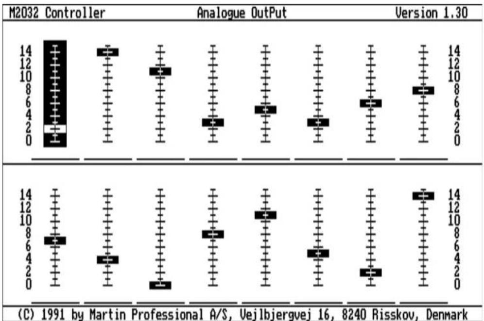
Martin 516 Dimmer Controller enables you to connect up to 16 non-intelligent lighting units per controller channel. The only function that can be controlled is the dimmer function but it is a useful asset which resembles a traditional lighting desk.
boxplot
| Category | Value | |----------------------|-------| | M2032 Controller | 14 | | Analogue OutPut | 12 | | Version 1.30 | 14 | | M2032 Controller | 10 | | Analogue OutPut | 8 | | Version 1.30 | 10 | | M2032 Controller | 6 | | Analogue OutPut | 4 | | Version 1.30 | 2 | | M2032 Controller | 0 | | Analogue OutPut | 0 | | Version 1.30 | 0 | | M2032 Controller | 0 | | Analogue OutPut | 0 | | Version 1.30 | 0 | | M2032 Controller | 0 | | Analogue OutPut | 0 | | Version 1.30 | 0 | | M2032 Controller | 0 | | Analogue OutPut | 0 |Fig 11. The Analogue Unit
Select an analog channel from the Sequence Editor screen and the screen shown in fig 11 appears. This represents a 16 channel desk. Use the trackball to select the channel required and to move the "fader" to set the light intensity. Click the left button to toggle between the two rows of faders, click the right button to return to the Sequence Editor screen. Please note that you cannot transmit a reset signal to the Dimmer Controller.
Additional Features available for the 2032 Controller
There are a number of new additional features that are available from Martin Professional which make the 2032 a much more powerful controller and will enhance your lightshow to the limits of your imagination.
2532 Direct Access Controller
The 2532 Direct Access Controller is a new add-on controller that links with up with the 2032 and results in much faster access to the functions of the 2032.
A simple ergonomic keyboard layout enables much faster programming and access to 56 programmed sequences via a matrix layout which includes a new flash facility.
Smpte Show Control Software
Developed by our own in-house software engineers, the new SMPTE Show control system is designed to give you full show control by allowing the generation and logging of smpte timecode for perfect synchronisation with your selected soundtrack. The system can command up to six 2032 controllers, which in turn, can command up to 192 RoboScan units or a staggering 3,072 separate Analogue Channels giving you endless control options from lightshows up to conferences, multi-media events and full production shows.
2032 PC Kit
The 2032 Software is now available so that it can be run from most standard P.C's. With this kit you will receive software, a Martin Professional Transmitter card and a mouse to run the system with, plus, of course, full instructions on how the system operates. The system is fully supported by software updates as they are released in the same way as the 2032 controller is.
RS 232 Interface
An RS 232 Interface is available for remote control of the 2032 controller enabling the call up of any scene or sequence using a standard RS 232 connection.
Compact Disc Timecode Interface
The revolutionary Compact Disc Timecode Interface allows logging from standard music Compact Discs. You can program the music selection as well as your own lightshow. It's also available as a master system using a standard P.C. for synchronising up to six 2032 controllers.
Details of these products are available from your Martin Professional Dealer.
Additional control options available from Martin Professional
DMX Interface
The Martin Professional DMX Interface enables anyone to control all Martin Professional products through any existing, or forthcoming DMX lighting control console. Among it's features are : Dual switchable voltage control, control of all Martin Professional intelligent products, full and reduced versions available to save valuable channel controls, LED's give a constant status display on the front of the unit, built with the lighting designer and operator in mind with new user-friendly controls, a compact unit that can be placed anywhere and responds exclusively to DMX 512.
Details of these products are available from your Martin Professional Dealer.
Glossary
| Channel | The controller is able to control up to 32 individual units. When configuring the controller each unit is assigned a channel number that corresponds to the address set on the unit itself. |
| Clicking | Moving the pointer to a specific point on the screen and pressing one of the buttons. |
| Configuration | This tells the controller what units to control via the serial link. The configuration must be correctly set before programming. |
| DIP switches | Small switches, located on the unit, which, in different combinations, setup the addresses of the lighting unit so that the commands from the controller can be interpreted. |
DSub-XLR cable The cable that connects the controller to the first unit on the link.
XLR-XLR cable The cable that connects one unit to the next unit on the link.
Escape If a certain function in the program doesn't offer a way Exit to exit (usually a field marked 'Exit' or 'Quit') pressing the right button will exit or escape the function.
Field A 'box' on the screen labelled with text, eg. 'COLOR'.
Function One of the features you may program on your units.
Gobo A perforated metal plate placed in front of a light beam to produce shadows to form different patterns.
Link The signal cable that connects the controller to the effect units.
Load Reading data or programs from diskette or hard disk.
Master channel The channel which is selected last - indicated by an extra frame around its field. All other selected channels will be programmed with the same settings as the Master Channel.
Microstepping A microstepping motor can be positioned much more precisely than a standard motor and can produce smooth, slow movements as well as fast movements.
Pan Movement of the mirror at 90 degrees to the longitudinal axis of the Roboscan.
Glossary (Continued)
| Pointer | The arrow shaped marker on the screen. The pointer is controlled either by the built in trackball or via a mouse. |
| Prompt | When the controller asks a question and waits for the user to answer. |
| Reset | Setting the controller or the lighting units to the default values (factory settings). |
| Save | Storing data on a diskette or hard disk. |
| Scene | Refers to an individual setting of some or all of the units linked to the controller. |
| Scroll | Moving a selection bar up and down through several selections. |
| Selecting Clicking | on a specific field (box) on the screen. The button to be pressed when selecting will always be the left button unless the right button is specifically mentioned. |
| Selection bar | This refers to a bar that may be moved up and down through several items. Select an item by pressing the left button. |
| Sequence | Refers to one or more related scenes to be executed by the controller. |
| Show | Refers to one or more groups of sequences to be executed by the controller. |
| Shutter | A device which makes the light flash at different speeds. |
| Slide-bar | A moveable bar on the screen which highlights the desired function. |
| Software | The programs which make the controller work. |
| Strobe rate | The rate at which the light is flashing. |
| Strobe | See shutter. |
| Symbol | The short form of a unit name eg.1016 for the Roboscan 1016. Used to label channels on ‘Sequence Editor’ and ‘Run Sequences’ screens. |
| Terminator-plug | This plug must terminate the link. If not the transmission may be heavily disturbed. |
| Tilt | Movement of the mirror parallel to the longitudinal axis of the Roboscan. |
Glossary (Continued)
Toggle Switching from one mode of operating to another or back.
Trig sources The method of telling the controller to move to the next scene. Auto Trigger generated by the controller (variable).
Manual Trigger generated by the operator by padding the "Trig" field.
Music Trigger generated by an independent sound source input.
Trig rate The time between consecutive scenes.
Trig level The sensitivity with which the controller detects a music trig.
Unit Refers to one of the units you may program with the M2032 controller.
Index
Address 5,13,51
Analog 16,24,48
APPENDIX A 32
APPENDIX B 36
Auto Trig 23,27
Auto Trig Rate 23
Centrepiece 46
Channel 13,16,17,23,36,45,5
Configuring the controller 12
Default rate 23
Default setting 20
Delete Scene 20
Delete Sequence 25,28
Delete Show 29
Designing a scene 19
DIP switch settings RoboColor 34
Roboscan 1004/1005 3 3
Roboscan 1020 33
Roboscan 804/805 32
RoboZap 35
Diskette 11,12,14
Follow mode 23
Frozen mode 24
Insert Scene 20
Insert Sequence 27
Link 10,51
Loop 27,28,30
Main menu 11,12,21
Main Toolbox 12,13,25
Manual Mode 30
Manual Trig 23
Music trig 10,23
Preparing a Data Diskette 14
Programming a Sequence 19
Programming a show 25
Programming Roboscans 36,45
Programming the RoboColor 42
Programming the RoboZap 39,41,46
Removing a sequence 28
Reset 20,24
RoboColor 24,43,44
Roboscan 16,23,36,37,45
RoboZap 24,39-42
RotatingGobos 37
Run Sequence 22,27
Run Show 30
Index (Continued)
Save 13,21,22,26
Sequence editor 16, 20-22, 40, 42
Show Editor 26
Terminator-plug 10
Time Out 31
Trackball 1 1
Trig Rate 23,27
- Table Of Contents (Continued)
- APPENDIX A
- Preface
- Introduction
- Installing and using 2032 Software, PC version.
- Hardware.
- Hardware Installation.
- Software.
- Floppy Disk Version
- Hard Disk Version
- Installing and using 2032 Software, PC version (Contd.) Hard Disk Version
- Installing to MS-DOS 5.0 systems.
- Using the mouse.
- Martin M2032 Controller - Package contents
- Connecting the controller
- WARNING!
- Getting started
- Configuring the controller
- Configuring the Controller (Continued)
- Preparing a Data Diskette
- DO NOT TRY TO MAKE A DATA DISKETTE WITH THE PROGRAM DISKETTE THAT CAME WITH THE CONTROLLER.
- Before starting to program
- Programming the controller
- The Sequence Editor
- Selecting channels
- The Sequence Editor (Continued)
- Selecting a row.
- The Master channel.
- Programming the units
- Programming Sequences
- Designing a scene
- Programming a Sequence
- Deleting a scene
- Inserting a scene
- The Reset option
- Saving a sequence
- Programming Sequences (Continued)
- Editing a Sequence
- Running Sequences
- Running a Sequence
- Running Sequences (Continued)
- Follow mode
- Frozen mode
- The Online / Offline function
- The Reset function
- Deleting a sequence
- Programming a Show
- Programming a Show (Continued)
- Inserting a Sequence
- Removing a Sequence
- Deleting a Show
- Running a Show
- Time Out mode:
- Selecting a Trig Mode in Run Show
- DIP switch settings for the RoboZap and RoboZap MSR 1200 and the Centrepiece
- APPENDIX B
- Programming of specific Martin lighting units
- Programming Roboscans
- Functions:
- Programming Roboscans (Continued)
- Programming the RobZap (Continued)
- Program
- Rotate Right
- Programming the RoboZap MSR 1200
- Programming the RoboZap MSR 1200 (Continued)
- Programming the RoboColor
- Programming the RoboColor (Continued)
- Programming the RoboColor MSD 200
- Programming the Centrepiece
- Functions :
- Additional Features available for the 2032 Controller
- PC Kit
- RS 232 Interface
- Compact Disc Timecode Interface
- DMX Interface
- Glossary
- Glossary (Continued)
- Index
- Index (Continued)
Brand : MARTIN
Model : 2032 Controller
Category : Lighting Controller