2504 Controller - Lighting Controller MARTIN - Free user manual and instructions
Find the device manual for free 2504 Controller MARTIN in PDF.


| Product Type | Lighting Controller |
| Brand | Martin |
| Model | 2504 Controller |
| DMX Channels | 250 |
| DMX Output Connector | 5-pin XLR |
| Control Protocol | DMX512 |
| Display | LCD |
| Controls | Faders, buttons |
| Power Supply | 9V DC |
| Power Consumption | 5W |
| Dimensions (W x H x D) | 483 x 88 x 200 mm |
| Weight | 3 kg |
| Housing | Metal |
| Operating Temperature | 0°C to 40°C |
| Key Functions | Scene programming, chase sequences, fixture control |
| Memory | Internal for scenes |
| Compatibility | DMX512 fixtures |
| Accessories Included | Power adapter, manual |
| Maintenance | Clean with dry cloth |
| Safety | Use specified power adapter |
| Spare Parts Availability | Contact Martin support |
| General Information | Designed for professional lighting control |
Frequently Asked Questions - 2504 Controller MARTIN
User questions about 2504 Controller MARTIN
0 question about this device. Answer the ones you know or ask your own.
Ask a new question about this device
Download the instructions for your Lighting Controller in PDF format for free! Find your manual 2504 Controller - MARTIN and take your electronic device back in hand. On this page are published all the documents necessary for the use of your device. 2504 Controller by MARTIN.
USER MANUAL 2504 Controller MARTIN
© 1996 Martin Professional A/S, Denmark.
All rights reserved. No part of this manual may be reproduced, in any form or by any means, without permission in writing from Martin Professional A/S, Denmark.
Printed in Denmark.
Revision #960123-PS
TABLE OF CONTENTS
INTRODUCTION 3
CONNECTING 4
LOCATING AND ADDRESSING THE ROBOSCANS ..... 5
Congratulations on your choice of the Martin 2504 controller, which is an easy-to-use preprogrammed intelligent lighting controller. The 2504 controller exists as two different versions: One that controls Martin Roboscan 805s and another that controls Martin Roboscan 812s. Both versions control up to 8 Roboscans individually, and even more (up to 32 Roboscans) may be connected by allowing several Roboscans share the same control address. Please note that all Sequences and Shows are programmed for 4 or 8 Roboscans, and additional Roboscans on the same address will all perform in exactly the same way.
The 2504 controller lets you choose between 40 preprogrammed Sequences, 5 Shows and a non-repeatable random Sequence. These can be triggered either manually, automatically or by music. It is also possible to enable a total blackout function manually.
The controller has an extra feature, which allows it to convert a standard RS-232 input-signal to a Martin RS-485 output-signal. This function can be used for those who wish to control the Roboscans (or other Martin intelligent lights) with their own controller. You may obtain further information about the protocol converting ability from your local Martin dealer.
section 2
CONNECTING
Fitting the mains plug
If necessary connect a three pin plug to the mains cable using
- the BROWN wire for the LIVE pin,
- the BLUE wire for the NEUTRAL pin and
- the GREEN/YELLOW wire for the EARTH (ground) pin.
Connecting the roboscans
To connect the Roboscans, supported by the 2504 controller, use the 3 pin XLR link cables that are supplied with the controller and Roboscans.
- First, connect the data output of the controller to the data input of the first Roboscan.
- Next, connect the data output of the first Roboscan to the data input of the next.
- Continue the link this way, always connecting output to input (daisy-chain), until all Roboscans are linked together.
- Finally, insert the male XLR termination plug, that is supplied with the controller, in the free output socket of the last Roboscan on the link. It is very important to insert this plug to ensure correct and error-free communication between the 2504 controller and the Roboscans.

| pin wire | |
| 1 | s |
| 2 hot (+) | |
| 3 cold (-) |
Extra XLR cables can be supplied by your Martin dealer. You may also use standard balanced microphone cable (twisted pair with screen) and 3 pin XLR plugs. The connections should be as per the table on the left
c section 3 e n LOCATING AND ADDRESSING THE ROBOSCANS
The Roboscans connected to the controller must be addressed from 1 to 8, as per diagrams figs. 2 - 5. The Roboscans will not respond to addresses higher than 8. Please refer to the user's manual of the relevant Roboscan, on how to set the DIP-switches.
Locating Roboscan 812s
The Roboscan 812 programs are designed to work with either 4 or 8 fixtures. Figure 2 on the left shows how to locate the fixtures. You may choose to use all 8 Roboscans (1 to 8) or just Roboscans number 1, 2, 3 and 4 or 5, 6, 7 and 8. Try re-addressing the Roboscans and run the programmes to see which configuration suits you best.
The position of the Roboscans should be adjusted so that all beams meet at the centre of the dance-floor/stage when selecting sequence number 1 from the controller (all mirrors in neutral position). There are not really any limitations of the coverage, but try to adjust the height so that the programs match the size of the stage/dance-floor.

Figure 2 shows how you can locate the Roboscan 812s. If you are using 4 Roboscans only, then omit 1, 2, 3 and 4 or 5, 6, 7 and 8.
Locating Roboscan 805s
The Roboscan 805 programs are designed to work with either 4 or 8 Roboscans. Figure 3 to 5 show different ways of locating the Roboscans. You may choose to use all 8 Roboscans (1 to 8) as shown in figure 3 or just Roboscans number 1, 2, 3 and 4 as shown in figures 4 and 5. Try to see which configuration suits you best. For the pre-programmed Sequences to work best, it is recommended that the size of the stage/dance floor should be 3 to 6 meters by 3 to 6 meters. The height should be between 2.5 and 3.5 meters.
The position and tilt-angle of the Roboscans should be adjusted so that all beams intersect in the centre of the “room” (half-mid between left and right, front and back, ceiling and floor) when the pan/tilt mirrors are in neutral position.
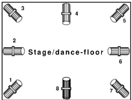
Figure 3 shows how you can locate the Roboscan 805s when all 8 Roboscans are being used.

Figure 4 (Left) and Figure 5 (Right) shows how you can locate the Roboscan 805s when only 4 of the Roboscans are being used.

section 4
Switching on the controller
After having connected the 2504 controller to the mains, you can switch it on by pressing the power switch at the upper left part of the 2504 front panel. The controller will now send a reset signal to all Roboscans on the data link. Note that this is the only way to reset the Roboscans from the controller. The controller then displays the following numbers one by one:
{25} {04} {X} {XX} {Y.Y}.
Brackets 3 and 4 indicates whether the controller is programmed for Roboscan
804s or 812s.
{8}{05} indicates Roboscan 805,
{8}{12} indicates Roboscan 812.
The last indication is the software version number.
Selecting sequences and shows
To preset a Sequence or a Show to run, simply use the [] and [] buttons until the desired Sequence/Show number appears in the display. Please refer to the following table. To execute the displayed Sequence or Show simply press [Enter].
| display read-out | information (Roboscan 805) | information (Roboscan 812) |
| {01} to {40} Sequence number Sequence number | ||
| {P1} | Show 1Sequence 1 to 10 | Show 1Sequence 3, 6, 17, 18, 35, 38, 39, 40 |
| {P2} | Show 2Sequence 11 to 20 | Show 2Sequence 2, 5, 14, 13, 10, 15, 12, 31, 36 |
| {P3} | Show 3Sequence 21to 30 | Show 3Sequence 7, 8, 11, 9, 16, 19, 20, 23, 34, 37 |
| {P4} | Show 4Sequence 31 to 40 | Show 4Sequence 21, 22, 33, 32, 24, 25, 4, 29, 28, 26, 27, 30 |
| {P5} | Show 5Sequence 1 to 40 | Show 5Sequence 2, 4, 6, 8, 10, 12, 14, 16, 18, 20, 22, 24, 26, 28, 30, 32, 34, 36, 38, 40, 1, 3, 5, 7, 9, 11, 13, 15, 17, 19, 21, 23, 25, 27, 29, 31, 33, 35, 37, 39 |
| {rA} Random sequence Random sequence | ||
| {PC} Protocol converter Protocol converter | ||
Selecting trig mode
The first program selected after power up, starts with ta pre-programmed default Trig rate. Changing from one Trig mode to another is done by pushing the desired Trig mode button (Manual, Auto or Music).
The current Trig mode is indicated by the dots in the display. If the Trig mode is Manual, the left dot is flashing every time the [Manual] button is pushed. If Auto Trig mode is selected the right dot flashes with the beat of the Trig rate. In Music Trig mode, both dots flash every time the built-in microphone triggers the 2504 controller.
AUTO TRIG RATE
To change the Auto Trig rate push [Auto] two or more times in the rhythm you wish the sequence to trigger.
By keeping [Auto] pressed two or more seconds the controller returns to the default Trig rate.
When choosing one of the 40 Sequences, the 5 Shows or the random Sequence, the controller will execute the selected program with the same Trig mode as the previous selected program, i.e. the Trig mode and Trig rate does not change when selecting a new sequence or show.
MANUAL TRIG
Pushing [Manual] switches to Manual Trig mode. The Sequence is triggered each time you push the [Manual] button.
MUSIC TRIG
Pushing [Music] switches to Music Trig mode. A built-in microphone will pick up the beat of the music and trigger the Sequence accordingly.
BLACKOUT
When [Blackout] is pushed all Roboscans blackout and the execution of the program stops. To re-activate execution push [Blackout] again.
appendix a
TECHNICAL
SPECIFICATIONS
Roboscan 805 configuration
• Pre-configured to control up to 8 Roboscan 805
• 40 pre-programmed sequences
• 268 scenes total
Roboscan 812 configuration
• Pre-configured to control up to 8 Roboscan 812
• 40 pre-programmed sequences
• 200 scenes total
General specifications
• Auto, manual and music trig (built-in microphone)
- Blackout function
- RS-232 input (may be used as RS-232 to Martin RS-485 converter)
- Two digit 20x25 mm LED display
- 19"/2U rack-mounting
- Dimensions (LxWxH): 483 x 65 x 89 mm (19 x 2.6 x 3.5")
• Weight: 1.0 Kg (2.2 lb)
• Shipping weight: 2.0 Kg (4.4 lb) -
Shipping dimensions (LxWxH): 580 x 260 x 150 mm (22.9 x 10.2 x 5.9")
• AC Voltage (EU model):210-250 V / 50-60 Hz
• AC Voltage (US model): 100-130 V / 50-60 Hz
• Power consumption: 2.5 W -
Link cable (standard): 5 meters (21'10")
- Link termination: 120 Ω
appendix b
TROUBLE SHOOTING GUIDE
| problem probable cause(s) suggested remedy | ||
| None of the Roboscans respond to the controller. | The controller is disconnected from the data link. | • Connect controller. |
| The controller may be in protocol converter mode. | • Use [↑] and [↓] to select a sequence or show and press [Enter]. | |
| Some Roboscans are not responding or respond erratically. | Bad data link connection. • Check connections/cables in daisy-chain and correct accordingly. | |
| Data link not terminated with 120 Ω termination plug. | • Insert termination plug in the last Roboscan on the data link. | |
| Incorrectly addressing (DIP-switch setting) of Roboscans. | • Ensure that all Roboscans are addressed between channel 1 and 8 only. | |
| Roboscans not powered on. • Power on Roboscans. | ||
| Roboscans have failed in the protocol auto-detection. | • Switch off the Roboscans and then back on again. In general, switch on the 2504 controller before the Roboscans. | |

- TABLE OF CONTENTS
- CONNECTING
- Fitting the mains plug
- Connecting the roboscans
- c section 3 e n LOCATING AND ADDRESSING THE ROBOSCANS
- Locating Roboscan 812s
- Locating Roboscan 805s
- Switching on the controller
- Selecting sequences and shows
- Selecting trig mode
- AUTO TRIG RATE
- MANUAL TRIG
- MUSIC TRIG
- BLACKOUT
- appendix a
- TECHNICAL
- SPECIFICATIONS
- Roboscan 805 configuration
- Roboscan 812 configuration
- General specifications
- appendix b
- TROUBLE SHOOTING GUIDE
Brand : MARTIN
Model : 2504 Controller
Category : Lighting Controller