
TH-D7E - Ham Radio KENWOOD - Free user manual and instructions
Find the device manual for free TH-D7E KENWOOD in PDF.

| Product Type | FM Dual-Band VHF/UHF Amateur Radio |
| Brand | KENWOOD |
| Model | TH-D7E |
| Frequency Bands | VHF: 144-146 MHz; UHF: 430-440 MHz |
| Modes | FM (F3E), GMSK (F1D), FSK (F2D) |
| Power Supply Voltage | External: 5.5 to 16 V DC (13.8 V nominal); Battery: 4.5 to 15 V (6 V nominal) |
| Supplied Battery | PB-38: NiCd 6 V / 650 mAh |
| Dimensions (W x H x D) | 54.0 x 119.5 x 35.5 mm (with PB-38 battery) |
| Weight | Approx. 340 g (with PB-38 battery, antenna, and accessories) |
| Number of Memory Channels | 200 channels |
| Display | Large LCD with alphanumeric display |
| Built-in TNC | Yes, AX.25 compatible for packet operations |
| APRS | Yes, with APRS format processing |
| CTCSS | 38 subaudible tone frequencies |
| Antenna | Supplied flexible antenna, 50 Ω impedance |
| Supplied Accessories | Antenna, PB-38 battery, wall charger, belt clip, wrist strap, connection cable, warranty card, instruction manual |
| Operating Temperature | -20 °C to +60 °C |
| Receiver Sensitivity (12 dB SINAD) | VHF/UHF: ≤ 0.18 μV |
| Transmit Power (H, 13.8 V) | VHF: 6 W; UHF: 5.5 W |
| Safety | Do not expose to moisture, do not transmit at high power for extended periods. Use only recommended accessories. |
| Maintenance and Cleaning | Clean with a soft dry cloth. Avoid solvents. |
| Repairability | Entrust any repairs to a KENWOOD authorized service center. |
Frequently Asked Questions - TH-D7E KENWOOD
User questions about TH-D7E KENWOOD
0 question about this device. Answer the ones you know or ask your own.
Ask a new question about this device
Download the instructions for your Ham Radio in PDF format for free! Find your manual TH-D7E - KENWOOD and take your electronic device back in hand. On this page are published all the documents necessary for the use of your device. TH-D7E by KENWOOD.
USER MANUAL TH-D7E KENWOOD
We are grateful you decided to purchase this KENWOOD FM Dual Bander. KENWOOD always provides Amateur Radio products which surprise and excite serious hobbyists. This transceiver is no exception. This time KENWOOD presents a handheld with a built-in TNC to make data communications much more convenient than before. KENWOOD believes that this product will satisfy your requests on both voice and data communications.
MODELS COVERED BY THIS MANUAL
The models listed below are covered by this manual.
TH-D7A: 144/440 MHz FM Dual Bander (U.S.A./ Canada)
TH-D7E: 144/430 MHz FM Dual Bander (Europe)
FEATURES
This transceiver has the following main features.
- Has a built-in TNC which conforms to the AX.25 protocol. With a portable computer, allows you to enjoy Packet operation quite easily.
- Includes a program for dealing with data formats supported by Automatic Packet/ Position Reporting System (APRS®).
- Is capable of receiving packet data on one band while receiving audio on another band.
- Contains a total of 200 memory channels to program frequencies and other various data. Allows each memory channel to be named using up to 8 alphanumeric and special ASCII characters.
- If programmed, the built-in Continuous Tone Coded Squelch System (CTCSS) rejects unwanted calls from other stations.
- Equipped with an easy-to-read large LCD with alphanumeric display capability.
- Employs a 4-way cursor key so that you can program most of the functions with only one hand.
Enhances the functions of an optional VC-H1 Interactive Visual Communicator designed for plug-and-play color slow-scan television (SSTV). - Utilizes Sky Command System II designed to control a KENWOOD HF transceiver at a remote location (TH-D7A only).

ATTENTION (U.S.A. Only):
The RBRC Recycle seal found on KENWOOD nickel-cadmium (Ni-Cd) battery packs indicates KENWOOD's voluntary participation in an industry program to collect and recycle Ni-Cd batteries after their operating life has expired. The RBRC program is an alternative to disposing Ni-Cd batteries with your regular refuse or in municipal waste streams, which is illegal in some areas.
For information on Ni-Cd battery recycling in your area, call (toll free) 1-800-8-BATTERY (1-800-822-8837).
KENWOOD's involvement in this program is part of our commitment to preserve our environment and conserve our natural resources.
One or more of the following statements may be applicable:
FCC WARNING
This equipment generates or uses radio frequency energy. Changes or modifications to this equipment may cause harmful interference unless the modifications are expressly approved in the instruction manual. The user could lose the authority to operate this equipment if an unauthorized change or modification is made.
INFORMATION TO THE DIGITAL DEVICE USER REQUIRED BY THE FCC
This equipment has been tested and found to comply with the limits for a Class B digital device, pursuant to Part 15 of the FCC Rules. These limits are designed to provide reasonable protection against harmful interference in a residential installation.
This equipment generates, uses and can generate radio frequency energy and, if not installed and used in accordance with the instructions, may cause harmful interference to radio communications. However, there is no guarantee that the interference will not occur in a particular installation. If this equipment does cause harmful interference to radio or television reception, which can be determined by turning the equipment off and on, the user is encouraged to try to correct the interference by one or more of the following measures:
Reorient or relocate the receiving antenna.
- Increase the separation between the equipment and receiver.
- Connect the equipment to an outlet on a circuit different from that to which the receiver is connected.
- Consult the dealer for technical assistance.
PRECAUTIONS
Please observe the following precautions to prevent fire, personal injury, or transceiver damage:
- Do not transmit with high output power for extended periods. The transceiver may overheat.
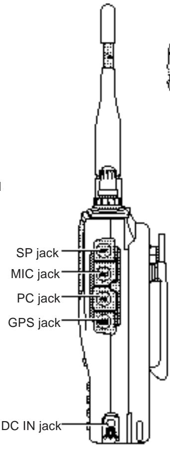
- Do not modify this transceiver unless instructed by this manual or by KENWOOD documentation.
- When using a regulated power supply, connect the specified DC cable (option) to the DC IN jack on the transceiver. The supply voltage must be between 5.5V and 16V to prevent damaging the transceiver.
- When connecting the transceiver to a cigarette lighter socket in a vehicle, use the specified cigarette lighter cable (option).
- Do not expose the transceiver to long periods of direct sunlight nor place the transceiver close to heating appliances.
- Do not place the transceiver in excessively dusty areas, humid areas, wet areas, nor on unstable surfaces.
- If an abnormal odor or smoke is detected coming from the transceiver, turn OFF the power immediately and remove the battery case or the battery pack from the transceiver. Contact your authorized KENWOOD dealer, customer service, or service station.
CONTENTS
SUPPLIED ACCESSORIES 1
CONVENTIONS FOLLOWED IN THIS MANUAL...... 1
CHAPTER 1 PREPARATION
INSTALLING THE NiCd BATTERY PACK 2
CHARGING THE NiCd BATTERY PACK 2
INSTALLING THE ANTENNA 3
INSTALLING THE HAND STRAP/ BELT HOOK...... 3
INSTALLING ALKALINE BATTERIES 4
CONNECTING WITH A REGULATED POWER
SUPPLY 5
CONNECTING WITH A CIGARETTE LIGHTER
SOCKET 5
CHAPTER ② FIRST QSO
CHAPTER ③ OPERATING BASICS
SWITCHING POWER ON/OFF 7
ADJUSTING VOLUME 7
SELECTING A BAND 7
SELECTING A FREQUENCY 7
ADJUSTING SQUELCH 8
TRANSMITTING 9
Selecting Output Power 9
CHAPTER 4 GETTING ACQUAINTED
ORIENTATION 10
INDICATORS 11
CURSOR KEYS 12
BAND A & B 12
BASIC TRANSCEIVER MODES 13
KEYPAD DIRECT ENTRY 15
CHAPTER 5 MENU SET-UP
MENU ACCESS 16
PROGRAMMING OFFSET 21
Selecting Offset Direction 21
Selecting Offset Frequency 21
Activating Tone Function 22
Selecting a Tone Frequency 22
AUTOMATIC REPEATER OFFSET 23
REVERSE FUNCTION 24
AUTOMATIC SIMPLEX CHECK (ASC) 24
TONE FREQ. ID 25
CHAPTER ⑦ MEMORY CHANNELS
SIMPLEX & REPEATER OR
ODD-SPLIT MEMORY CHANNEL? 26
STORING SIMPLEX FREQUENCIES OR
STANDARD REPEATER FREQUENCIES 27
STORING ODD-SPLIT REPEATER
FREQUENCIES 27
RECALLING A MEMORY CHANNEL 28
CLEARING A MEMORY CHANNEL 28
NAMING A MEMORY CHANNEL 29
CALL CHANNEL (TH-D7A ONLY) 30
Recalling the Call Channel 30
Reprogramming the Call Channel 30
MEMORY-TO-VFO TRANSFER 31
CHANNEL DISPLAY 31
PARTIAL OR FULL RESET? 32
CHAPTER 8 SCAN
SELECTING SCAN RESUME METHOD 34
VFO SCAN 35
MEMORY SCAN 35
Locking Out a Memory Channel 36
MHz SCAN 36
PROGRAM SCAN 37
Setting Scan Limits 37
Using Program Scan 38
CALL/VFO SCAN (TH-D7A ONLY) 38
CALL/MEMORY SCAN (TH-D7A ONLY) 38
CHAPTER 9 CONTINUOUS TONE CODED SQUEELCH SYSTEM (CTCSS)
SELECTING A CTCSS FREQUENCY 39
USING CTCSS 40
CTCSS FREQ. ID 40
CHAPTER 10 DUAL TONE MULTI-FREQUENCY (DTMF) FUNCTIONS
MANUAL DIALING 41
TX Hold 41
AUTOMATIC DIALER 42
Storing a DTMF Number in Memory 42
Transmitting a Stored DTMF Number 43
CHAPTER 11 MICROPHONE CONTROL
CHAPTER 12 AUXILIARY FUNCTIONS
DIRECT FREQUENCY ENTRY 45
CHANGING FREQUENCY STEP SIZE 46
PROGRAMMABLE VFO 46
TONE ALERT 47
BEEP ON/OFF 47
ADJUSTING VOLUME BALANCE 48
LAMP FUNCTION 48
ADJUSTING DISPLAY CONTRAST 48
BLANKING A BAND DISPLAY 48
AUTOMATIC POWER OFF (APO) 49
BATTERYSAVER 49
POWER-ONMESSAGE 50
TRANSCEIVER LOCK 50
TX INHIBIT 51
SWITCHING AM/FM MODE (TH-D7A ONLY) 51
ADVANCED INTERCEPT POINT (AIP) 51
SWITCHING TX DEVIATION (TH-D7E ONLY) 51
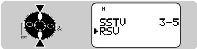
SLOW-SCAN TELEVISION (SSTV) WITH VC-H1
ENTERINGCALLSIGN/MESGAGE/RSV 58
SELECTING COLOR FOR CALL SIGN/
MESSAGE/ RSV 59
EXECUTING SUPERIMPOSITION 59
VC-H1 CONTROL 60
CHAPTER

PROGRAMMING A CALL SIGN 66
SELECTING YOUR STATION ICON 67
ENTERING LATITUDE/ LONGITUDE DATA 68
SELECTING A POSITION COMMENT 69
ENTERING STATUS TEXT 70
PROGRAMMING A GROUP CODE 71
PROGRAMMING A PACKET PATH 72
SELECTING BEACON TRANSMIT METHOD 74
SELECTING BEACON TRANSMIT INTERVAL 75
RESTRICTING RECEPTION OF APRS DATA 75
CHAPTER

APRS®MESSAGE
OPERATION FLOW 76
RECEIVING AMESSAGE 77
ACCESSING RECEIVEDAPRS MESSAGES 78
ENTERING AMESSAGE 79
TRANSMITTING AMESSAGE 80
CHAPTER

WIRELESS REMOTE CONTROL (TH-D7A ONLY)
PREPARATION 81
PROGRAMMINGCALLSIGNS 86
PROGRAMMING A TONE FREQUENCY 86
EQUIPMENT CONNECTIONS
CONNECTING EQUIPMENT FOR
REMOTE CONTROL 96
CONNECTING OTHER EXTERNAL
EQUIPMENT 96
CHAPTER

SPECIFICATIONS
APPENDIX
QUICK REFERENCE GUIDE
INDEX
SUPPLIED ACCESSORIES
| Accessory | Part Number | Quantity |
| Antenna | T90-0634-XX | 1 |
| NiCd battery pack For TH-D7A1 For TH-D7E2 | W09-0911-XX W09-0909-XX | 1 |
| Battery charger For TH-D7A For TH-D7E | W08-0437-XX W08-0440-XX | 1 |
| Belt hook | J29-0631-XX | 1 |
| Hand strap | J69-0342-XX | 1 |
| Cable with a 2.5 mm (1/10") 3-conductor plug3 | E30-3374-XX | 1 |
| Warranty card | — | 1 |
| Instruction manual | B62-1004-XX | 1 |
1 PB-39 (9.6 V, 600 mAh)
2 PB-38 (6 V, 650 mAh)
3 Use this accessory to modify the cable end of your GPS receiver {page 61}.
CONVENTIONS FOLLOWED IN THIS MANUAL
The writing conventions described below have been followed to simplify instructions and avoid unnecessary repetition.
| Instruction | What to Do |
| Press [KEY]. | Press and release KEY. |
| Press [KEY] (1 s). | Press and hold KEY for 1 second or longer. |
| Press [KEY1], [KEY2]. | Press KEY1 momentarily, release KEY1, then press KEY2. |
| Press [KEY1]+[KEY2]. | Press and hold KEY1, then press KEY2. |
| Press [KEY]+ POWER ON. | With transceiver power OFF, press and hold KEY, then press the POWER switch. |
1
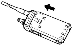
INSTALLING THE NiCd BATTERY PACK
1 Position the two grooves on the inside bottom corners of the battery pack over the corresponding guides on the back of the transceiver.
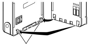
Guide
2 Slide the battery pack along the back of the transceiver until the release latch on the base of the transceiver locks the battery pack in place.
3 To remove the battery pack, push up the release latch, then slide the battery pack back.
Release latch
CHARGING THE NiCd BATTERY PACK
After installing the NiCd battery pack, charge the battery pack. The battery pack is provided uncharged.
1 Confirm that the transceiver power is OFF.
- While charging the battery pack, leave the transceiver power OFF.
2 Insert the DC plug from the charger into the DC IN jack on the transceiver.
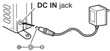
3 Insert the charger AC plug into an AC wall outlet.
- Charging starts and will take approximately 16 hours for PB-38 or 15 hours for PB-39.
4 After 16 hours (PB-38) or 15 hours (PB-39), remove the charger DC plug from the transceiver DC IN jack.
5 Remove the charger AC plug from the AC wall outlet.
CAUTION
Exceeding the specified charge period shortens the useful life of the NiCd battery pack.
The provided charger is designed to charge only the provided PB-38 or PB-39 NiCd battery pack. Charging other models of battery packs will damage the charger and battery pack.
The following table shows the approximate battery life (hours) relative to the transmit output power.
| Batteries | VHF Band | UHF Band | ||||
| H | L | EL | H | L | EL | |
| PB-39 NiCd | 3 | 6 | 9 | 3 | 6 | 9 |
| PB-38 NiCd | 4.5 | 7 | 10 | 4 | 7 | 10 |
Note:
Charge the NiCd battery pack within an ambient temperature of between 5^ and 40^ (41°F and 104°F). Charging outside this range may not fully charge the pack.
Repeatedly recharging a fully charged NiCd battery pack, or almost fully charged pack, shortens its operating time. To resolve this problem, use the pack until it is completely discharged. Then recharge the pack to full capacity.
If the operating time of a fully charged NiCd battery pack is much shorter than before, the battery life is over. Replace the pack.
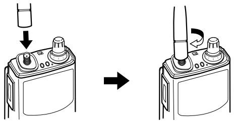
INSTALLING THE ANTENNA
Hold the provided antenna at its base, and screw the antenna into the connector on the top panel of the transceiver until it is snug.
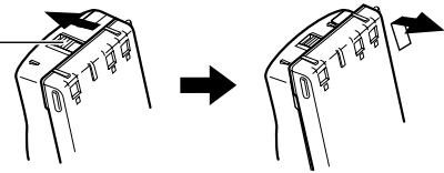
INSTALLING THE HAND STRAP/ BELT HOOK
If desired, attach the provided hand strap and/ or belt hook.
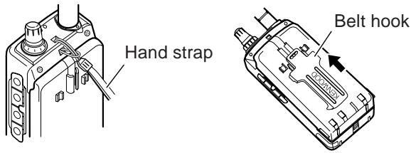
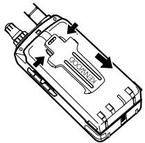
To remove the belt hook, pull the belt hook downward while pushing its tabs from both sides.
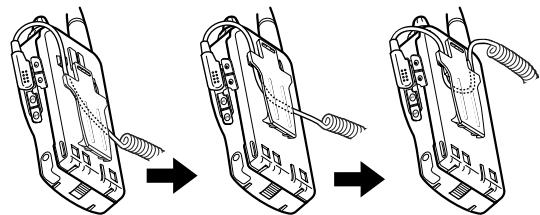
To lock the cable of an optional speaker microphone, first position the cable over the left groove on the transceiver. Then install the belt hook. Last, position the cable over the right groove.
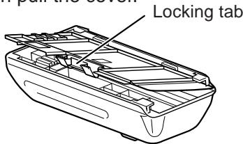
INSTALLING ALKALINE BATTERIES
With an optional BT-11 battery case, you can use commercially available alkaline batteries in such occasions as camping or emergency operations.
1 To open the battery case cover, push on the locking tab, then pull the cover.
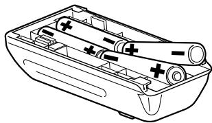
2 Insert four AA (LR6) alkaline batteries.
- Be sure to match the battery polarities with those marked on the bottom of the battery case.
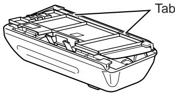
3 Align the two tabs on the battery case cover, then close the cover until the locking tab clicks.
4 To install the battery case onto (or remove from) the transceiver, follow steps 1 to 3 for INSTALLING THE NiCd BATTERY PACK {page 2}.
WARNING
Do not install the batteries in a hazardous environment where sparks could cause an explosion.
Never discard old batteries in fire because extremely high temperatures can cause batteries to explode.
Note:
It is recommended to use high quality alkaline batteries rather than manganese batteries to enjoy longer periods of battery life. Do not use commercially available NiCd batteries.
If you will not use the transceiver for a long period, remove the batteries from the battery case.
Do not use different kinds of batteries together.
When the battery voltage is low, replace all four old batteries with new ones.
The following table shows the approximate battery life (hours) relative to the transmit output power.
| Batteries | VHF Band | UHF Band | ||||
| H | L | EL | H | L | EL | |
| Alkaline | 14 | 22 | 33 | 14 | 22 | 30 |
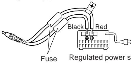
CONNECTING WITH A REGULATED POWER SUPPLY
To connect the transceiver with an appropriate regulated power supply, use an optional PG-2W DC cable.
1 Confirm that the power switches of both the transceiver and power supply are OFF.
2 Connect the optional PG-2W DC cable to the power supply; red lead to positive (+) terminal, and black lead to negative (-) terminal.
3 Connect the barrel plug on the DC cable to the DC IN jack on the side of the transceiver.
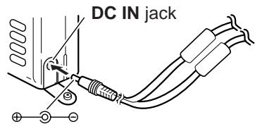
Note:
Only use the power supplies recommended by your authorized KENWOOD dealer.
The supply voltage must be between 5.5 V and 16 V to prevent damaging the transceiver. If input voltage exceeds approximately 18 V, warning beeps sound and a warning message appears.
CONNECTING WITH A CIGARETTE LIGHTER SOCKET
To connect the transceiver with the cigarette lighter socket in your vehicle, use an optional PG-3J Cigarette Lighter cable.
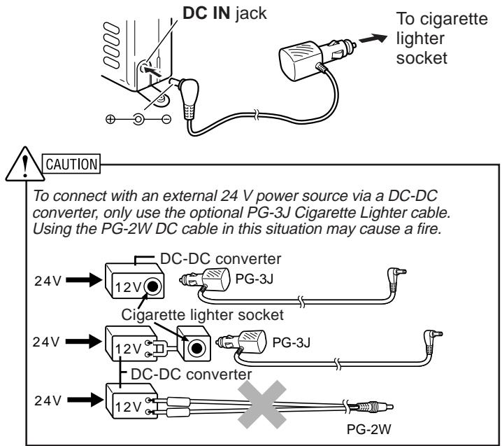
Note: If input voltage exceeds approximately 18 V, warning beeps sound and a warning message appears.
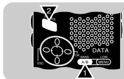
FIRST QSO
2
The 7 steps given here will get you on the air in your first QSO right away. So, you can enjoy the exhilaration that comes with opening a brand new transceiver.
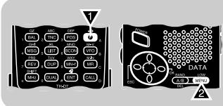
1
Press the POWER switch for 1 second or longer.
2

Turn the VOL control clockwise to the 11 o'clock position.
3
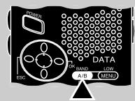
Press [A/B] to select band A or B.
4
Press [UP]/[DWN] or turn the Tuning control to select a frequency.
5
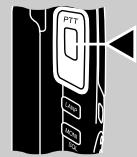
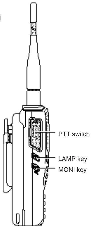
Press and hold the PTT switch, then speak into the microphone in a normal tone of voice.
6
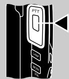
Release the PTT switch to receive.
7 Repeat steps 5 and 6 to continue communication.
Note: When received signals are too weak to recognize, press and hold [MONI] to hear clearer signals. You will, however, also hear background noise.
SWITCHING POWER ON/OFF
1 Press the POWER switch (1 s) to switch ON the transceiver.
- A double beep sounds.
2 To switch OFF the transceiver, press the POWER switch (1 s) again.
ADJUSTING VOLUME
Turn the VOL control clockwise to increase the audio level and counterclockwise to decrease the audio level.

- If background noise is inaudible because of the Squelch function, press and hold [MONI], then adjust the VOL control. While pressing [MONI], you will hear background noise.
SELECTING A BAND
Press [A/B] to select band A or B.
- The cursor indicates the current band.
SELECTING A FREQUENCY
Press [UP]/[DWN] or turn the Tuning control to select a frequency.
- Pressing and holding [UP]/[DWN] causes the frequency to step repeatedly.
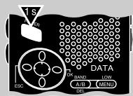
- To change frequencies in steps of 1 MHz, press [MHz] first. The 1 MHz digit blinks. Pressing [MHz] again cancels this function.
- You can also select frequencies by directly entering digits from the keypad. See "DIRECT FREQUENCY ENTRY" {page 45}.
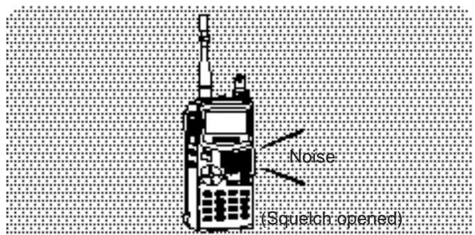
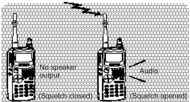
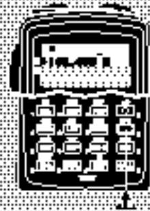
ADJUSTING SQUELCH
Selecting the correct squelch level relieves you from listening to background noise output from the speaker when no signals are present. The appropriate squelch level depends on ambient noise conditions. You can program a different level for band A and B.
The current squelch level is incorrect.
The current squelch level is correct.
1 Press [F], [MONI].
- The SQL meter indicates the current squelch level. The default is level 2; 4 segments are visible.
![KENWOOD TH-D7E - Press [F], [MONI]. - 1](/content/2025/01/83300/images/ca74db44f28b1ceb19bbf6820dd68f5c6229c5c2a1ecc9517a10dbafc0ce1aa7.jpg)
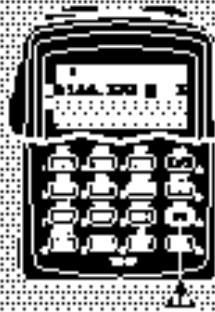
2 Press [UP]/[DWN] to select from 6 squelch levels.
- Select the level at which the background noise is just eliminated when no signal is present.
- The higher the level selected, the stronger the signals must be to receive.
![KENWOOD TH-D7E - Press [F], [MONI]. - 2](/content/2025/01/83300/images/38c8dac4402ffedf0dd6c68dda8147ea2daf5459a6d19a4d3c3e80b94494408e.jpg)
![KENWOOD TH-D7E - Press [F], [MONI]. - 3](/content/2025/01/83300/images/f14318257b9e04fa5e4969ca2dd2d5f399db20ed60027da148bfef7fa45e0936.jpg)
3 Press [OK] to complete the setting.
TRANSMITTING
1 To transmit, press and hold the PTT switch and speak into the microphone in a normal tone of voice.
- Indicator A or B lights red depending on which band you have selected.
- The battery meter appears to show the current relative battery charge.

- Speaking too close to the microphone, or too loudly, may increase distortion and reduce intelligibility of your signal at the receiving station.
2 When you finish speaking, release the PTT switch.
Time-Out Timer: Holding down the PTT switch for more than 10 minutes causes the transceiver to generate a beep and stop transmitting. Release, then press the PTT switch to resume transmitting. You cannot switch this function OFF.
CAUTION
The recommended duty cycle is 1 minute of transmission and 3 minutes of reception. Extended transmissions in the high power mode may cause the back of the transceiver to get hot.
Transmitting with the supplied antenna near other electronic equipment can interfere with that equipment. Also, transmitting near a poorly regulated power supply, that is not recommended by KENWOOD, may cause the power supply to output an extremely high voltage. This voltage could damage both your transceiver and any other equipment connected to the power supply.
Note: If input voltage exceeds approximately 18 V while using an external power source, warning beeps sound and a warning message appears.
Selecting Output Power
Selecting lower transmit power is a wise method to reduce battery consumption, if communication is still reliable. You can program a different power for band A and B.
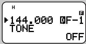
Press [F], [MENU] to select high (default), low, or economic low power (lowest).
- "H", "L", or "EL" appears to show the current selection.
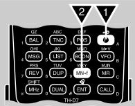
ORIENTATION
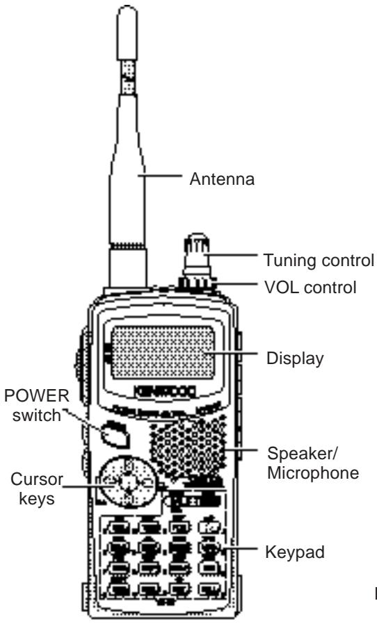
TX/RX indicator
INDICATORS
On the upper section of the display you will see various indicators that show what you have selected.
| EL | Economic low transmit power | [F], [MENU] to restore default | 9 |
| L | Low transmit power | [F], [MENU], [F], [MENU] to restore default | 9 |
| H | High transmit power | Default setting | 9 |
| C | TNC power ON | [TNC], [TNC] | 54 |
| N | Packet mode | [TNC] | 54 |
| A | APRS Beacon function | [BCON] | 74 |
| U | Full Duplex mode | [DUP] | 55 |
| I | Automatic Simplex Check | [REV] | 24 |
| - | Transceiver Lock | [F] (1s) | 50 |
| CT | CTCSS | [F], [3] | 40 |
| T | Tone function | [F], [1] | 22 |
| + | Plus offset direction | [F], [MHz], [F], [MHz] (TH-D 7E: one more [F], [MHz]) | 21 |
| - | Minus offset direction | [F], [MHz] (TH-D 7E: one more [F], [MHz]) | 21 |
| = | Minus offset direction (-7.6 MHz) | [F], [MHz] | 21 |
| R | Reverse function | [REV] | 24 |
| # | Tone Aet | [F], [ENT] | 47 |
| ★ | Memory Channel Lockout | [F], [0] | 36 |
| D | Function Select mode | [ESC] | 13 |
1 TH-D7E only

Shows the strength of received signals. While transmitting, shows the current relative battery charge.
Note: Electromagnetic fields, such as those produced by static electricity, may occasionally cause the display to function abnormally. However, the display will typically return to normal operation within a couple of minutes.
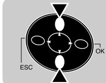
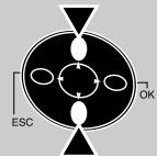
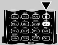
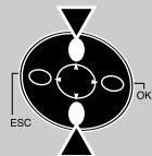
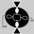
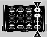
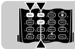
CURSOR KEYS
This transceiver employs 4 cursor keys so that you can program most of the functions with only one hand.

UP/ DWN keys
The UP/ DWN keys function in the exact same way as the Tuning control. These keys change frequencies, memory channels, or other selections, depending on the current transceiver mode.
Note: You can use the Tuning control instead of the UP/ DWN keys in each operation step. This manual often omits the Tuning control to simplify descriptions.
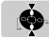
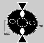
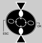
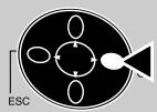
OK key
Press to move to the next step or to complete the setting in various selection modes such as Function Select or Menu mode.
ESC key
Press to move back to the previous step or to quit the setting in various selection modes such as Function Select or Menu mode.
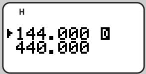
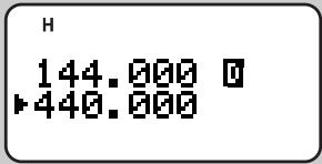
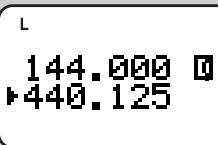
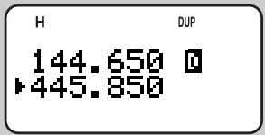
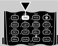
BAND A & B
In this manual, bands recalled beside “圆” and “圆” are referred to as band A and band B. The band A default is VHF (144 MHz) and the band B default is UHF. In band A you can also recall a 118 MHz sub-band (TH-D7A only). In band B you can also recall a VHF (144 MHz) sub-band.
This transceiver is capable of simultaneously receiving on 2 bands (A and B). So, for example, it is possible to receive packet data on one VHF frequency while receiving audio on another VHF frequency. To transmit, you must select either band. "B" indicates the current data band {page 55}.
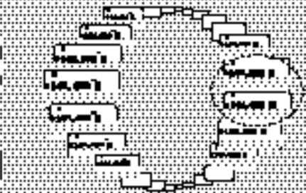
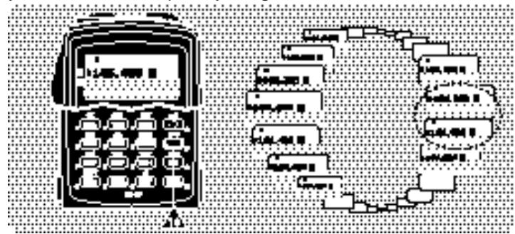
The following diagram should help you understand how to select or recall the desired band.
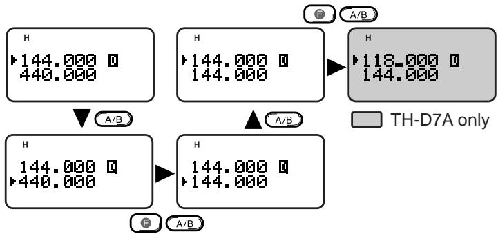
Note:
You cannot recall another band by pressing [F], [A/B] in Memory Recall mode. First press [VFO] to select VFO mode.
The 118 MHz band cannot be used for transmitting.
BASIC TRANSCEIVER MODES
This section introduces you to the basic modes you can select on this transceiver.
VFO mode
Press [VFO] to select. In this mode you can change the operating frequency by pressing [UP]/[DWN] or entering digits directly from the keypad {page 45}.
Memory Recall mode
Press [MR] to select. In this mode you can recall the desired memory channel by pressing [UP]/[DWN] or entering digits directly from the keypad {page 28}. For further information, refer to "MEMORY CHANNELS" {page 26}.
Function Select mode
Press [F] to select. In this mode you can scroll F-1 through F-8 (except F-6) by pressing [UP]/[DWN]; to access F-6, first select the 118 MHz band {page 51}. After accessing the desired function, press [OK], then press [UP]/[DWN] to select the desired parameter. Last, press [OK] again to complete the setting. After recalling a memory channel, you can also access F-0 and F-9. On the TH-D7E you cannot access F-6.
Pressing [F], [0] ~ [9] is a much simpler method than the above. For example, pressing [F], [1] switches the Tone function ON or OFF. This method is described in the appropriate sections in this manual.
Menu mode
Press [MENU] to select. In this mode you can access the desired menu item by pressing [UP]/[DWN] and [OK] or entering digits directly from the keypad. For further information, refer to "MENU SET-UP" {page 16}.

Full Duplex mode
Press [DUP] to select. In this mode the transceiver is capable of simultaneously transmitting and receiving signals. So, it is possible to transmit audio on the current band while receiving packet data on another band. For further information, refer to "FULL DUPLEX" {page 55}.
Packet mode
Press [TNC] twice to select. In this mode, you can send commands to the built-in TNC from a personal computer {page 54}.
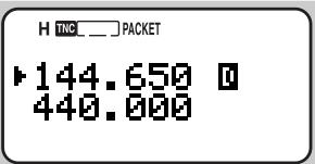
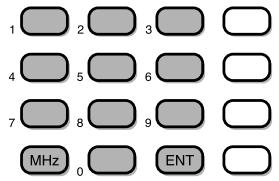
KEYPAD DIRECT ENTRY
The keypad allows you to make various entries depending on which mode the transceiver is in.
In VFO or Memory Recall mode, use the keypad to select a frequency {page 45} or memory channel number {page 28}. Press [ENT] first.
In Menu mode, use the keypad to select a menu item. For example, pressing [1], [4], [1] in sequence selects Menu 1-4-1 (DATA BAND).
To manually send a DTMF number, press and hold the PTT switch, then press the keys on the keypad {page 41}.

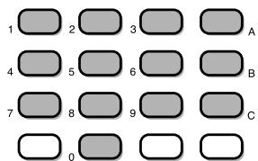
You can also use the keypad to program a memory channel name {pages 29 and 42}, Power-ON message {page 50}, or other character strings. For example, each press of [TNC] switches entry as A, B, C, a, b, c, then 2. Press [DUAL] to switch 0 and space. Press [ENT] to switch among the special ASCII characters.
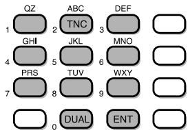
The selectable special characters are listed below:
| ? | ! | , | . | , | - | / | & | # |
| ( | ) | < | > | ; | : | " | @ |
Note: Pressing [UP]/[DWN] allows you to select more special ASCII characters than above.
The Menu system on this transceiver consists of 3 levels.
| Level 1 | 1 | 2 | ||||||||||||||||
| Level 2 | 1 | 2 | 3 | 4 | 5 | 1 | 2 | 3 | 4 | |||||||||
| Level 3 | 1 | 2 | 1 | 2 | 1 | 2 | 3 | 4 | 1 | 2 | 1 | 2 | 3 | 4 | 5 | 6 | 7 | |
| Menu 1-3-1 | ||||||||||||||||||
MENU ACCESS
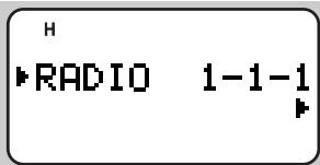
1 Press [MENU] to enter Menu mode.
- The current level 1 No. blinks.
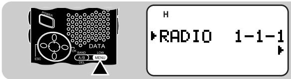
2 Press [UP]/[DWN] to select the appropriate level 1 No.
3 Press [OK].
- The current level 2 No. blinks.
4 Press [UP]/[DWN] to select the appropriate level 2 No.
- To move back to level 1, press [ESC] instead.
- To exit Menu mode, press [MENU].
5 Press [OK].
6 For Menu 1-1 to 1-5, repeat steps 4 and 5 to select level 3.
7 Press [UP]/[DWN] to select a parameter.
- The procedure in this step differs depending on which menu item you selected. See the appropriate sections in this manual.
8 Press [OK] to complete the setting.
9 Press [MENU] to exit Menu mode.
After pressing [MENU] in step 1, you can also enter level Nos. to quickly select a menu item. For example, pressing [1], [4], [1] in sequence selects Menu 1-4-1 (DATA BAND). This method is described in the appropriate sections in this manual.
MENUCONFIGURATION
| Level 1 | Level 2 | Level 3 | Selections | Default | Ref. page | |||
| 1 | RADIO | 1 | DISPLAY | 1 | Power-ON Message | See reference page. | HELLO !! | 50 |
| 2 | Contrast | Level 1 (min.) ~ 16 (max.) | Level 8 | 48 | ||||
| 2 | SAVE | 1 | Battery Saver Interval | 0.2/ 0.4/ 0.6/ 0.8/ 1.0/ 2.0/ 3.0/ 4.0/ 5.0 sec./ OFF | 1.0 sec. | 49 | ||
| 2 | Automatic Power Off (APO) | 30/ 60 minutes/ OFF | 30 minutes | 49 | ||||
| 3 | DTMF | 1 | Number Store | See reference page. | — | 42 | ||
| 2 | TX speed | Fast/ Slow | Fast | 43 | ||||
| 3 | TX Hold | ON/ OFF | OFF | 41 | ||||
| 4 | Pause | 100/ 250/ 500/ 750/ 1000/ 1500/ 2000 msec. | 500 msec. | 43 | ||||
| 4 | TNC | 1 | Data band select | Band A/ Band B | Band A | 55 | ||
| 2 | DCD sense | Both bands/ Data band only | Data band only | 55 | ||||
| 5 | AUX | 1 | Automatic Repeater Offset | ON/ OFF | ON | 23 | ||
| 2 | Scan Resume | Time-Operated/ Carrier-Operated/ Seek | Time- Operated | 34 | ||||
| 3 | Beep function | OFF/ KEY/ KEY+NEW DATA/ ALL | ALL | 47,56, 63,77 | ||||
| 4 | Tuning Enable | ON/ OFF | OFF | 50 | ||||
| 5 | TX Inhibit | ON/ OFF | OFF | 51 | ||||
| 6 | Advanced Intercept Point (TH-D7A) | ON/ OFF | OFF | 51 | ||||
| 1 | RADIO | 5 | AUX | 6 | TX Hold, 1750 Hz (TH-D7E) | ON/ OFF | OFF | 22 |
| 7 | Reset (TH-D7A) | Partial (VFO)/ Full/ No | — | 32 | ||||
| 7 | VHF band narrow TX deviation (TH-D7E) | ON/ OFF | OFF | 51 | ||||
| 8 | Advanced Intercept Point (TH-D7E) | ON/ OFF | OFF | 51 | ||||
| 9 | Reset (TH-D7E) | Partial (VFO)/ Full/ No | — | 32 | ||||
| Level 1 | Level 2 | Selections | Default | Ref. page | ||||
| 2 | APRS | 1 | My call sign | See reference page. | — | 66 | ||
| 2 | GPS receiver | Not used/ NMEA | Not used | 62 | ||||
| 3 | Latitude/ longitude data | See reference page. | — | 68 | ||||
| 4 | Position comment | See reference page. | — | 69 | ||||
| 5 | Station icon | See reference page. | — | 67 | ||||
| 6 | Status text | See reference page. | — | 70 | ||||
| 7 | Beacon transmit interval | .5/ 1/ 2/ 3/ 5/ 10/ 20/ 30 minutes | 5 minutes | 75 | ||||
| 8 | Packet path | See reference page. | — | 72 | ||||
| 9 | Beacon transmit method | Manual/ PTT/ Auto | Manual | 74 | ||||
| A | Group code | See reference page. | — | 71 | ||||
| B | Reception restriction distance | 10 ~ 2500 in steps of 10/ OFF | OFF | 75 | ||||
| C | Unit | Mile and °F/ Kilometer and °C | Mile and °F | 65 | ||||
| Level 1 | Level 2 | Selections | Default | Ref. page | ||||
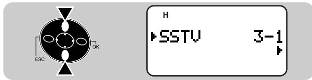
| 3 | SSTV | 1 | My call sign | See reference page. | — | 58 | ||
| 2 | Color for call sign | White/ Black/ Blue/ Red/Magenta/ Green/ Cyan/Yellow | White | 59 | ||||
| 3 | Message | See reference page. | — | 58 | ||||
| 4 | Color for message | White/ Black/ Blue/ Red/Magenta/ Green/ Cyan/Yellow | White | 59 | ||||
| 5 | RSV report | See reference page. | — | 58 | ||||
| 6 | Color for RSV report | White/ Black/ Blue/ Red/Magenta/ Green/ Cyan/Yellow | White | 59 | ||||
| 7 | Superimposition Execute | See reference page. | — | 59 | ||||
| 8 | SSTV mode | See reference page. | — | 57 | ||||
| 9 | VC-H1 Control | ON/ OFF | OFF | 60 | ||||
| 4 | SKYCMD(TH-D7A only) | 1 | Commander call sign | See reference page. | — | 86 | ||
| 2 | Transporter call sign | See reference page. | — | 86 | ||||
| 3 | Tone frequency select | See reference page. | — | 86 | ||||
| 4 | Sky Command mode select | Commander/ Transporter/OFF | OFF | 85 | ||||
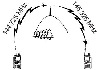
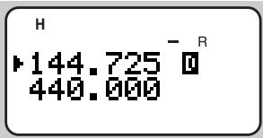
Repeaters, which are often installed and maintained by radio clubs, are usually located on mountain tops or other elevated locations. Generally they operate at higher ERP (Effective Radiated Power) than a typical station. This combination of elevation and high ERP allows communications over much greater distances than communications without using repeaters.
Most repeaters use a receive and transmit frequency pair with a standard or non-standard offset (odd-split). In addition, some repeaters must receive a tone from the transceiver to allow it to access. For details, consult your local repeater reference.
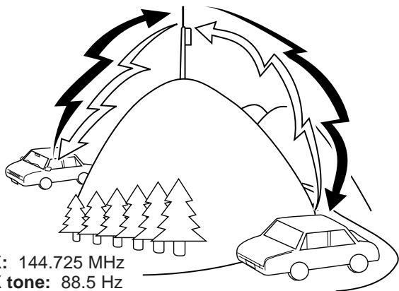
TX: 144.725 MHz
TX tone: 88.5 Hz
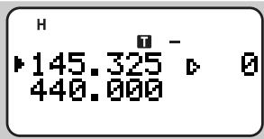
RX: 145.325 MHz
TX: 144.725 MHz
TX tone: 88.5 Hz
RX: 145.325 MHz
Offset Programming Flow
Select a band.
Select a receive frequency.
3 Select an offset direction.
4 Select an offset frequency. (Only when programming odd-split repeater frequencies)
Activate the Tone function. (If necessary)
Select a tone frequency. (If necessary)
If you store the above data in a memory channel, you need not reprogram every time. See "MEMORY CHANNELS" {page 26}.
PROGRAMMING OFFSET
First select band A or B by pressing [A/B]. Then, if necessary, press [F], [A/B] to recall the sub-band.
Selecting Offset Direction
Select whether the transmit frequency will be higher (+) or lower (-) than the receive frequency.
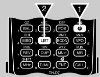
Press [F], [MHz] to switch the offset direction.
- "+" or "-" appears to indicate which offset direction is selected.
- To program -7.6 MHz offset on the TH-D7E (UHF only), repeatedly press [F], [MHz] until "==" appears.
If the offset transmit frequency falls outside the allowable range, transmitting is inhibited. Use one of the following methods to bring the transmit frequency within the band limits:
- Move the receive frequency further inside the band.
- Change the offset direction.
Note: While using an odd-split memory channel or transmitting, you cannot change the offset direction.
Selecting Offset Frequency
To access a repeater which requires an odd-split frequency pair, change the offset frequency from the default which is used by most repeaters. The default offset frequency on the VHF band is 600kHz no matter which market version; the default on the UHF band is 5 MHz (TH-D7A) or 1.6 MHz (TH-D7E).
1 Press [F], [5] to select "F-5 (OFFSET)".
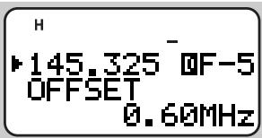
2 Press [UP]/[DWN] to select the appropriate offset frequency.
- The selectable range is from 0.00 MHz to 29.95 MHz in steps of 50 kHz.
3 Press [OK] to complete the setting.
TH-D7E Only: If you have selected “ ” for the offset direction, you cannot change the default (7.6 MHz).
Note: After changing the offset frequency, the new offset frequency will also be used by Automatic Repeater Offset.
Activating Tone Function
Press [F], [1] to switch the Tone function ON (or OFF).
- "T" appears when the Tone function is ON.

Note: You cannot use the Tone and CTCSS functions simultaneously. Switching the Tone function ON after activating the CTCSS deactivates the CTCSS.
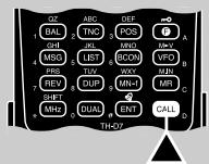
TH-D7E Only: When you access repeaters that require 1750 Hz tones, you need not activate the Tone function. No matter which selection you make here, simply pressing [CALL] without pressing the PTT switch causes the transceiver to transmit a 1750 Hz tone.
Selecting a Tone Frequency
1 Press [F], [2] to select "F-2 (TONE FREQ)".
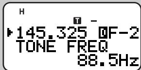
2 Press [UP]/[DWN] to select the appropriate tone frequency.
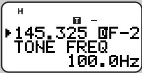
3 Press [OK] to complete the setting.
| No. | Freq. (Hz) | No. | Freq. (Hz) | No. | Freq. (Hz) | No. | Freq. (Hz) |
| 01 | 67.0 | 11 | 97.4 | 21 | 136.5 | 31 | 192.8 |
| 02 | 71.9 | 12 | 100.0 | 22 | 141.3 | 32 | 203.5 |
| 03 | 74.4 | 13 | 103.5 | 23 | 146.2 | 33 | 210.7 |
| 04 | 77.0 | 14 | 107.2 | 24 | 151.4 | 34 | 218.1 |
| 05 | 79.7 | 15 | 110.9 | 25 | 156.7 | 35 | 225.7 |
| 06 | 82.5 | 16 | 114.8 | 26 | 162.2 | 36 | 233.6 |
| 07 | 85.4 | 17 | 118.8 | 27 | 167.9 | 37 | 241.8 |
| 08 | 88.5 | 18 | 123.0 | 28 | 173.8 | 38 | 250.3 |
| 09 | 91.5 | 19 | 127.3 | 29 | 179.9 | ||
| 10 | 94.8 | 20 | 131.8 | 30 | 186.2 |
TH-D7E Only: To transmit a 1750Hz tone, simply press [CALL] without pressing the PTT switch. Release [CALL] to quit transmitting. You can also make the transceiver remain in the transmit mode for 2 seconds after releasing [CALL]; a 1750Hz tone is not continuously transmitted. Access Menu 1-5-6 (1750 Hz HOLD) and select "ON".
AUTOMATIC REPEATER OFFSET
This function automatically selects an offset direction, according to the frequency that you select on the VHF band. The transceiver is programmed for offset direction as shown below. To obtain an up-to-date band plan for repeater offset direction, contact your national Amateur Radio association.
U.S.A. and Canada versions
This complies with the standard ARRL band plan.
| 144.0 | 145.5 | 146.4 | 147.0 | 147.6 |
| 145.1 | 146.0 | 146.6 | 147.4 | 148.0 MHz |
| S | - | S | + | S | - | + | S | - |
S: Simplex
European versions
144.0 145.6 145.8 146.0 MHz
| S | - | S |
S: Simplex
Note: Automatic Repeater Offset does not function when Reverse is ON. However, pressing [REV] after Automatic Repeater Offset has selected an offset (split) status, exchanges the receive and transmit frequencies.
1 Press [MENU] to enter Menu mode.
2 Press [1], [5], [1] to select "1-5-1 (AUTO OFFSET)".

3 Press [UP]/[DWN] to switch the function ON (default) or OFF.

4 Press [OK] to complete the setting.
5 Press [MENU] to exit Menu mode.
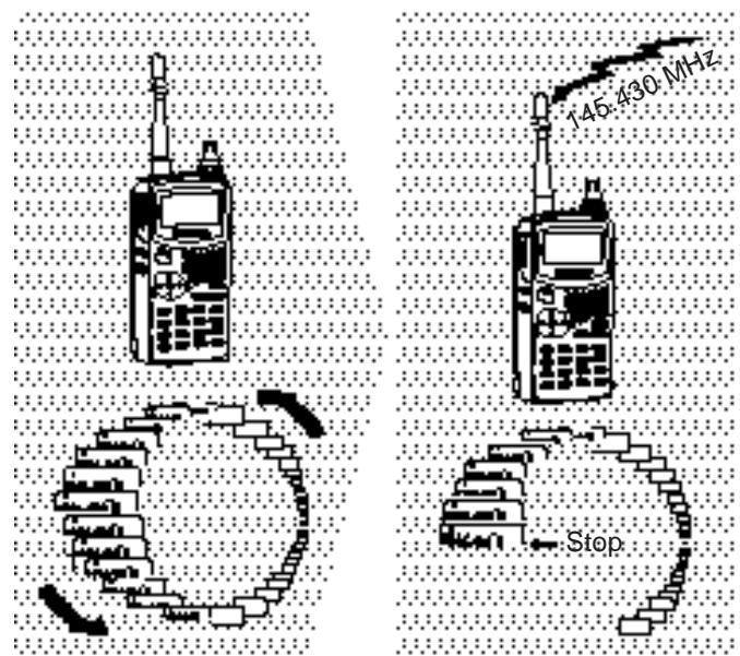
REVERSE FUNCTION
The reverse function exchanges a separate receive and transmit frequency. So, while using a repeater, you can manually check the strength of a signal that you receive directly from the other station. If the station's signal is strong, both stations should move to a simplex frequency and free up the repeater.
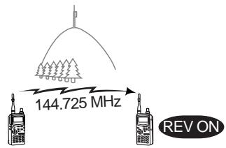
TX: 144.725 MHz TX: 144.725 MHz TX: 144.725 MHz RX: 145.325 MHz RX: 145.325 MHz RX: 144.725 MHz
Press [REV] to switch the Reverse function ON (or OFF).
- "R" appears when the function is ON.
Note:
If pressing [REV] places the transmit frequency outside the allowable range, then pressing the PTT switch causes an error beep to sound; transmission is inhibited.
If pressing [REV] places the receive frequency outside the allowable range, an error beep sounds and no reversal occurs.
Automatic Repeater Offset does not function while Reverse is ON.
You cannot switch Reverse ON or OFF while transmitting.
AUTOMATIC SIMPLEX CHECK (ASC)
While using a repeater, ASC periodically monitors the strength of a signal that you receive directly from the other station. If the station's signal is strong enough to allow direct contact without a repeater, the ASC indicator on the display begins blinking.
Press [REV] (1 s) to switch the function ON.
- "R" appears when the function is ON.
![KENWOOD TH-D7E - Press [REV] (1 s) to switch the function ON. - 1](/content/2025/01/83300/images/26132e21454a07315c50f0bd4ebac5556a86286425c264fa9c286c45ac2a6b0a.jpg)
While direct contact is possible, the ASC indicator blinks.
- To quit the function, press [REV] momentarily.
Note:
Pressing the PTT switch causes the ASC indicator to quit blinking.
ASC does not function if your transmit and receive frequencies are the same (simplex operation).
ASC does not function while scanning.
Activating ASC while using Reverse switches Reverse OFF.
If you recall a memory channel or the Call channel that contains Reverse ON status, ASC is switched OFF.
ASC causes receive audio to be momentarily intermitted every 3 seconds.
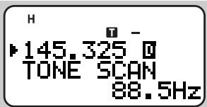
TONE FREQ. ID
This function scans through all tone frequencies to identify the incoming tone frequency on a received signal. You may use the function to find which tone frequency is required by your local repeater.
1 Press [F], [2] (1 s) to activate the function.
- The Tone function is switched ON.
- If you access "F-2 (TONE FREQ)" using [UP]/[DWN] in Function Select mode, press [OK] (1 s) to activate the function.
- To reverse scan direction, press [UP] (upward scan) or [DWN] (downward scan).
- To quit the function, press [ESC].
- When the tone frequency is identified, the identified frequency appears and blinks.
2 Press [OK] to program the identified frequency in place of the currently set tone frequency.
- The previous frequency display is restored with the Tone function remained ON. You may press [F], [1] to switch the Tone function OFF.
- Press [ESC] if you do not want to program the identified frequency.
- Press [UP]/[DWN] while the identified frequency is blinking, to resume scanning.
MEMORY CHANNELS
In memory channels, you can store frequencies and related data that you often use. Then you need not reprogram those data every time. You can quickly recall a programmed channel by simple operation. A total of 200 memory channels are available for bands A and B.
7
SIMPLEX & REPEATER OR ODD-SPLIT MEMORY CHANNEL?
You can use each memory channel as a simplex & repeater channel or odd-split channel. Store only one frequency to use as a simplex & repeater channel or two separate frequencies to use as an odd-split channel. Select either application for each channel depending on the operations you have in mind.
Simplex & repeater channel allows:
Simplex frequency operation
- Repeater operation with a standard offset (If an offset direction is stored)
Odd-split channel allows:
- Repeater operation with a non-standard offset
Note:
Not only can you store data in memory channels, but you can also overwrite existing data with new data.
If you have recalled a memory channel on the non-current band (A or B), you cannot select the same channel on the current band to program data.
The data listed below can be stored in each memory channel:
| Parameter | Simplex & Repeater | Odd-split |
| Receive frequency | Yes | Yes |
| Transmit frequency | Yes | |
| Tone frequency | Yes | Yes |
| Tone ON | Yes | Yes |
| CTCSS frequency | Yes | Yes |
| CTCSS ON | Yes | Yes |
| Offset direction | Yes | N/A |
| Offset frequency | Yes | N/A |
| Reverse ON | Yes | N/A |
| Frequency step size | Yes | Yes |
| Memory channel lockout | Yes | Yes |
| Memory channel name | Yes | Yes |
| AM/FM mode selection (TH-D7A only) | Yes | Yes |
Yes: Can be stored in memory.
N/A: Cannot be stored in memory.
STORING SIMPLEX FREQUENCIES OR STANDARD REPEATER FREQUENCIES
1 Select the desired band.
2 Press [VFO].
3 Press [UP]/[DWN] to select the desired frequency.
- You can also directly enter digits from the keypad. See page 45.
4 If storing a standard repeater frequency, select the following data:
- Offset direction {page 21}
- Tone ON, if necessary {page 22}
- Tone frequency, if necessary {page 22}
If storing a simplex frequency, you may select other related data (CTCSS ON, CTCSS freq., etc.).
5 Press [F], [MR].
- A memory channel number appears and blinks.
- “ ” indicates the current channel is empty; “ ” appears instead, if the channel contains data.
6 Press [UP]/[DWN] to select the desired memory channel.
7 Press [OK].
STORING ODD-SPLIT REPEATER FREQUENCIES
Some repeaters use a receive and transmit frequency pair with a non-standard offset. If you store two separate frequencies in a memory channel, you can operate on those repeaters without programming the offset frequency and direction.
1 Store the desired receive frequency and related data by using the procedure given for simplex or standard repeater frequencies.
2 Press [UP]/[DWN] to select the desired transmit frequency.
3 Press [F], [MR].
4 Press [UP]/[DWN] to select the memory channel programmed in step 1.
5 Press [PTT]+[OK].
- The transmit frequency is stored in the memory channel.
Note:
When you recall an odd-split memory channel, "+" and "-" appear on the display. To confirm the transmit frequency, press [REV].
Transmit Offset status and Reverse status are not stored in an odd-split memory channel.
RECALLING A MEMORY CHANNEL
1 Select the desired band.
2 Press [MR] to enter Memory Recall mode.
- The memory channel used last is recalled.
3 Press [UP]/[DWN] to select the desired memory channel.
- You cannot recall an empty memory channel.
To restore VFO mode, press [VFO].
You can also recall a memory channel by direct entry from the keypad. In Memory Recall mode press [ENT], then enter the channel number. To recall channel 3, for example, press [ENT], [0], [0], [3].
Note:
When you recall an odd-split memory channel, “+” and “-” appear on the display. Press [REV] to display the transmit frequency.
After recalling a memory channel, you may program data such as Tone or CTCSS. These settings, however, are cleared once you select another channel or the VFO mode. To permanently store the data, overwrite the channel contents {page 27}.
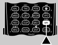
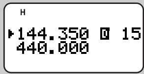
CLEARING A MEMORY CHANNEL
Use the following procedure to clear an individual memory channel. Full Reset {page 32} is a quick way to clear all memory channels.
1 Recall the desired memory channel.
2 Switch OFF the power to the transceiver.
3 Press [MR]+ POWER ON.
- A confirmation message appears.
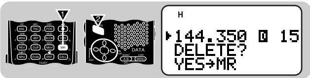
- To quit clearing the memory channel, press [ESC].
4 Press [MR] again.
- The contents of the memory channel are erased.
Note: If you have recalled a memory channel on the non-current band (A or B), you cannot select the same channel on the current band to clear.
NAMING A MEMORY CHANNEL
You can name memory channels using up to 8 alphanumeric characters. When you recall a named memory channel, its name appears on the display instead of the stored frequency. Names can be call signs, repeater names, cities, names of people, etc.
1 Recall the desired memory channel.
2 Press [F], [9] to select "F-9 (MEMORY NAME)".
The first digit blinks.

3 Press [UP]/[DWN] to select the first digit.
- You can enter alphanumeric characters plus special ASCII characters.
4 Press [OK].
- The cursor moves to the next digit.
5 Repeat steps 3 and 4 to enter up to 8 digits.
- Pressing [OK] after selecting the 8th digit completes the programming.
- To complete programming after entering less than 8 digits, press [OK] twice.
Each press of [ESC] causes the cursor to move backward. - Pressing [A/B] deletes the digit at which the cursor is blinking.
After storing a memory name, pressing [MN<-f] switches the display between the memory name and frequency.
You can also use the keypad to enter alphanumeric characters in step 3. For example, each press of [TNC] switches entry as A, B, C, a, b, c, then 2. Press [DUAL] to switch 0 and space. Press [ENT] to switch among the special ASCII characters.
Note:
You can also name the Program Scan {page 37} and DTMF {page 42} channels, but you cannot name the Call channel {page 30}.
You can assign names only to memory channels in which you have stored frequencies and related data.
The stored names can be overwritten by repeating steps 1 to 5.
The stored names also are erased by clearing memory channels.
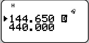
CALL CHANNEL (TH-D7A ONLY)
The Call channel can always be selected quickly no matter what mode the transceiver is in. For instance, you may use the Call channel as an emergency channel within your group. In this case, the Call/VFO scan {page 38} will be useful.
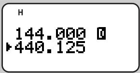
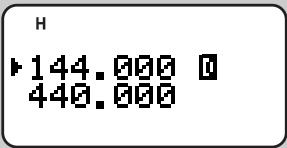
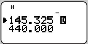
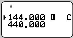
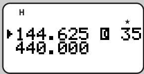
The default frequency stored in the Call channel is 144.000 MHz for the VHF band and 440.000 MHz for the UHF band. The Call channel can be reprogrammed either as a simplex & repeater or odd-split channel.
Note: Unlike channels 0 to 199 the call channel cannot be cleared.
Recalling the Call Channel
1 Select the desired band.
2 Press [CALL] to recall the Call channel.
- "C" appears.
- To restore the previous mode, press [CALL] again.
Reprogramming the Call Channel
1 Select the desired band.
2 Press [VFO].
3 Select the desired frequency and related data (Tone, CTCSS, etc.).
- When you program the Call channel as an odd-split channel, select a receive frequency.
4 Press [F], [CALL].
- The selected frequency and related data are stored in the Call channel.
- The previous mode is restored.
To also store a transmit frequency, proceed to the next step.
5 Select the desired transmit frequency.
6 Press [F].
7 Press [PTT]+[CALL].
- The transmit frequency is stored in the Call channel, and the previous mode is restored.
Note:
Transmit Offset status and Reverse status are not stored in an odd-split Call channel.
To store data other than frequencies, select the data in step 3 not step 5.
MEMORY-TO-VFO TRANSFER
You may sometimes want to search for other stations or a clear frequency, near the frequency stored in a memory channel or the Call channel. In this case first transfer the contents of a memory channel or the Call channel to the VFO.
1 Recall the desired memory channel or the Call channel.
2 Press [F], [VFO].

- The entire contents of the memory channel or the Call channel are copied to the VFO.
Note:
A transmit frequency from an odd-split memory channel or odd-split Call channel is not transferred to the VFO. To transfer a transmit frequency, press [REV], then press [F], [VFO].
Lockout status and memory names are not copied from a memory channel to the VFO.
If you recall the Call channel in step 1, simply pressing [UP]/[DWN] also transfers the contents to the VFO. The frequency, however, is changed by one step.
CHANNEL DISPLAY
When in this mode, the transceiver displays only memory channel numbers (or memory names if stored) instead of frequencies.
Press [A/B]+ POWER ON to switch the function ON (or OFF).
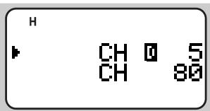
Note: You cannot switch this function ON if you have not used both bands A and B to store frequencies.
When in Channel Display mode, you can use only the following functions:
| Power ON/OFF | Band Select |
| Squelch Level Adjust | Monitor |
| Transmit | Transmit Power Select |
| Memory Channel Select | Direct Memory Channel Entry |
| Lamp ON | Lamp ON Latch |
| Offset Direction Select | Reverse |
| Full Duplex | Memory Scan |
| Partial/ Full Reset | Tone Alert |
| Transceiver Lock | Audio Balance Select |
| Band Display Blank | 1750 Hz Tone (TH-D7E) |
| DTMF Number (Stored) Transmit |
PARTIAL OR FULL RESET?
If your transceiver seems to be malfunctioning, initializing the transceiver may resolve the problem.
Use Full Reset to initialize all settings that you have customized. Partial (VFO) Reset does not initialize the following settings:
| Memory channels | Call channel |
| DTMF channels | Memory channel lockout |
| Power-ON message | Menu 3-1 ~ 3-6 (SSTV) |
| Menu 2-1/ 2-3 ~ 2-8/ 2-A/ 2-B (APRS) | |
| Menu 4-1 ~ 4-3 (SKY CMD)(TH-D7A only) | |
Note: While using the Transceiver Lock function, you cannot perform Partial Reset nor Full Reset.
VHF Band Defaults
| Version | VFO Freq. | Freq. Step Size | Tone Freq. |
| TH-D7A | 144.000 MHz | 5 kHz | 88.5 Hz |
| TH-D7E | 144.000 MHz | 12.5 kHz | 88.5 Hz |
UHF Band Defaults
| Version | VFO Freq. | Freq. Step Size | Tone Freq. |
| TH-D7A | 440.000 MHz | 25 kHz | 88.5 Hz |
| TH-D7E | 430.000 MHz | 25 kHz | 88.5 Hz |
1 Press [F] + POWER ON.
- “RESET?” appears.
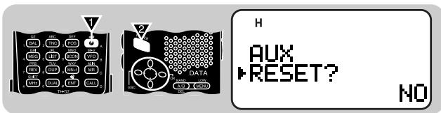
- You can also use Menu 1-5-7 (TH-D7A) or Menu 1-5-9 (TH-D7E).
2 Press [UP]/[DWN] to select Partial (VFO) Reset or Full Reset.
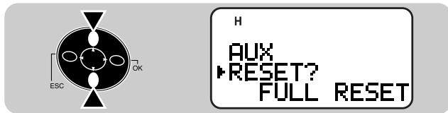
3 Press [OK].
- A confirmation message appears.
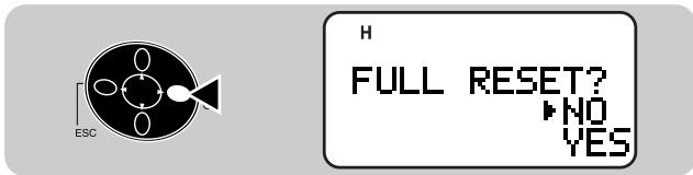
4 Press [UP]/[DWN] to select Yes (or No).
5 Press [OK].
Scan is a useful feature for hands-off monitoring of your favorite frequencies. Becoming comfortable with all types of Scan will increase your operating efficiency.
Note:
Adjust the squelch level before using Scan. Selecting a squelch level too low could cause Scan to stop immediately.
You cannot start Scan while Tone Alert is ON.
While using CTCSS, Scan stops for any signal received; however, you will hear audio only when the signal contains the same CTCSS tone that you selected.
Starting Scan switches OFF the Automatic Simplex Check.
This transceiver provides the following types of scans:
| Scan Type | Scan Range |
| VFO Scan | All frequencies tunable on the band |
| Memory Scan | Frequencies stored in the memory channels |
| MHz Scan | All frequencies within a 1 MHz range |
| Program Scan | All frequencies in the range selected on the band |
| Call/VFO Scan¹ | Call channel plus the current VFO frequency |
| Call/Memory Scan¹ | Call channel plus the selected memory channel |
1 TH-D7A only
SELECTING SCAN RESUME METHOD
The transceiver stops scanning at a frequency (or memory channel) on which a signal is detected. It then continues scanning according to which resume mode you select. You can choose one of the following modes. The default is Time-operated mode.
Time-Operated mode
The transceiver remains on a busy frequency (or memory channel) for approximately 5 seconds, and then continues to scan even if the signal is still present.
- Carrier-Operated mode
The transceiver remains on a busy frequency (or memory channel) until the signal drops out. There is a 2 second delay between signal drop-out and scan resumption.
- Seek mode
The transceiver remains on a busy frequency (or memory channel) even after the signal drops out and does not automatically resume scanning.
Note: To temporarily stop scanning and monitor weak signals, press and hold [MONI]. Release the key to resume scanning.
1 Press [MENU] to enter Menu mode.
2 Press [1], [5], [2] to select "1-5-2 (SCAN RESUME)".

3 Press [UP]/[DWN] to select Time-Operated (default), Carrier-Operated, or Seek.

4 Press [OK] to complete the setting.
5 Press [MENU] to exit Menu mode.
VFO SCAN
VFO Scan monitors all frequencies tunable on the band, using the current frequency step size.

1 Select the desired band.
2 Press [VFO] (1 s).
- Scan starts at the frequency currently displayed.
- The 1 MHz decimal blinks while scanning is in progress.
- To reverse scan direction, press [UP] (upward scan) or [DWN] (downward scan).
3 To quit VFO Scan, press [ESC].
MEMORY SCAN
Use Memory Scan to monitor all memory channels programmed with frequency data.
1 Select the desired band.
2 Press [MR] (1 s).
- Scan starts with the channel last recalled.
- The 1 MHz decimal blinks while scanning is in progress.
- To reverse scan direction, press [UP] (upward scan) or [DWN] (downward scan).
3 To quit Memory Scan, press [ESC].
Note:
On the current band at least 2 or more memory channels must contain data and must not be locked out.
The L0 to L9 and U0 to U9 memory channels are not scanned.
You can also start Memory Scan when in Channel Display mode. While Scan is being interrupted, the channel number blinks.
Locking Out a Memory Channel
Select memory channels that you prefer not to monitor while scanning.
1 Recall the desired memory channel.
2 Press [F], [0] to switch Lockout ON (or OFF).
- A star appears above the channel number when the channel is locked out.
Note:
The L0 to L9 and U0 to U9 memory channels cannot be locked out.
If you have recalled a memory channel on the non-current band (A or B), you cannot select the same channel on the current band to lock out.
MHz SCAN
MHz Scan monitors a 1 MHz segment of the band, using the current frequency step size. The current 1 MHz digit determines the limits of the scan. For example, if the current frequency is 145.400 MHz, then the scan range would be from 145.000 MHz to 145.995 MHz. The exact upper limit depends on the current frequency step size.
1 Select the desired band.
2 Press [VFO] to select VFO mode.
3 Select a frequency within the desired 1 MHz segment.
4 Press [MHz] (1 s) to start MHz Scan.
- Scan starts at the frequency currently displayed.
- The 1 MHz decimal blinks while scanning is in progress.
- To reverse scan direction, press [UP] (upward scan) or [DWN] (downward scan).
5 To quit MHz Scan, press [ESC].
PROGRAM SCAN
Program Scan is identical with VFO Scan except that you select the frequency range of the scan.
Setting Scan Limits
You can store up to 10 scan ranges in memory channels L0/U0 to L9/U9.
1 Select the desired band.
2 Press [VFO].
3 Select the desired frequency as the lower limit.
4 Press [F], [MR].
5 Press [UP]/[DWN] to select a channel in the range L0 to L9.

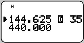
145.100 L3 440.000
6 Press [OK].
- The lower limit is stored in the channel.
7 Select the desired frequency as the upper limit.
8 Press [F], [MR].
9 Press [UP]/[DWN] to select a matching channel in the range U0 to U9.
If you have selected for example L3 in step 5, select U3.
![KENWOOD TH-D7E - Press [OK]. - 1](/content/2025/01/83300/images/da4173dfb7aa9f42ecdefeffe95c27a9f3aedeee0343bf01155b08e880c7bf5d.jpg)
H 145.900 U3 440.000
10 Press [OK].
- The upper limit is stored in the channel.
To confirm the stored scan limits, press [MR], then select the L and U channels.
Note:
The lower limit must be lower in frequency than the upper limit.
The lower and upper frequency step sizes must be equal.
The lower and upper limits must be selected on the same band.
Using Program Scan
1 Select the appropriate band.
2 Press [VFO].
3 Select a frequency equal to or between the programmed scan limits.
4 Press [VFO] (1 s).
- Scan starts at the frequency currently displayed.
- The 1 MHz decimal blinks while scanning is in progress.
- To reverse scan direction, press [UP] (upward scan) or [DWN] (downward scan).
5 To quit Program Scan, press [ESC].
Note:
If the step size of the current VFO frequency differs from that of the programmed frequencies, you cannot use Program Scan.
If the step size differs between the lower limit and the upper limit, you cannot use Program Scan.
If the current VFO frequency is within more than one programmed scan range, the range stored in the smallest channel number is used.
CALL/VFO SCAN (TH-D7A ONLY)
Use Call/VFO Scan to monitor both the Call channel and the current VFO frequency on the selected band.
1 Select the desired band.
2 Press [VFO].
3 Select the desired frequency.
4 Press [CALL] (1 s) to start Call/VFO Scan.
- The 1 MHz decimal blinks while scanning is in progress.
5 To quit Call/VFO Scan, press [ESC].
CALL/MEMORY SCAN (TH-D7A ONLY)
Use Call/Memory Scan to monitor both the Call channel and the desired memory channel.
1 Recall the desired memory channel.
2 Press [CALL] (1 s) to start Call/Memory Scan.
- The 1 MHz decimal blinks while scanning is in progress.
- The Call channel on the same band as of the selected memory channel is used for Scan.
3 To quit Call/Memory Scan, press [ESC].
Note: The memory channel last used is scanned even if it has been locked out.
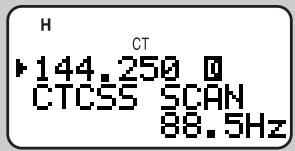
CONTINUOUS TONE CODED SQUEELCH SYSTEM (CTCSS)
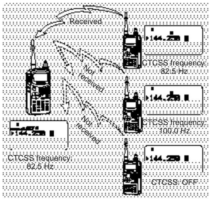
You may sometimes want to hear calls from only specific persons. The Continuous Tone Coded Squelch System (CTCSS) allows you to ignore (not hear) unwanted calls from other persons who are using the same frequency. First select the same CTCSS tone as selected by the other persons in your group. A CTCSS tone is subaudible and is selectable from among the 38 standard tone frequencies.
Note: CTCSS does not cause your conversation to be private. It only relieves you from listening to unwanted conversations.
SELECTING A CTCSS FREQUENCY
1 Press [A/B] to select band A or B.
If necessary, press [F], [A/B] to recall the sub-band.
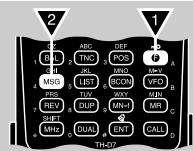
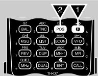
2 Press [F], [4] to select "F-4 (CTCSS FREQ)".
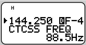
3 Press [UP]/[DWN] to select the appropriate CTCSS frequency.
- The selectable frequencies are the same as for the tone frequency. See the table given in "Selecting a Tone Frequency" {page 22}.
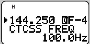
4 Press [OK] to complete the setting.
USINGCTCSS
1 Press [A/B] to select band A or B.
If necessary, press [F], [A/B] to recall the sub-band.
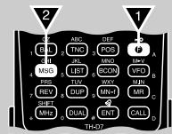
2 Press [F], [3] to switch the CTCSS function ON (on OFF).
- "CT" appears when CTCSS is ON.
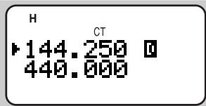
You will hear calls only when the selected tone is received. To answer the call, press and hold the PTT switch, then speak into the microphone.
Note:
You cannot use the CTCSS and Tone functions simultaneously. Switching the CTCSS function ON after activating the Tone function deactivates the Tone function.
If you select a high CTCSS frequency, receiving audio or noise that contains the same frequency portions may cause CTCSS to function incorrectly. To prevent noise from causing this problem, select an appropriate squelch level {page 8}.
CTCSS FREQ. ID
This function scans through all CTCSS frequencies to identify the incoming CTCSS frequency on a received signal. You may find it useful when you cannot recall the CTCSS frequency that the other persons in your group are using.
1 Press [F], [4] (1 s) to activate the function.
- The CTCSS function is switched ON.
- If you access “F-4 (CTCSS FREQ)” using [UP]/[DWN] in Function Select mode, press [OK] (1 s) to activate the function.
- To reverse scan direction, press [UP] (upward scan) or [DWN] (downward scan).
To quit the function, press [ESC]. - When the CTCSS frequency is identified, the identified frequency appears and blinks.
2 Press [OK] to program the identified frequency in place of the currently set CTCSS frequency.
- The previous frequency display is restored with the CTCSS function remained ON.
- Press [ESC] if you do not want to program the identified frequency.
- Press [UP]/[DWN] while the identified frequency is blinking, to resume scanning.
Note: Received signals are audible while scanning is in progress.
DUAL TONE MULTI-FREQUENCY (DTMF) FUNCTIONS
The keys on the keypad also function as DTMF keys; the 12 keys found on a push-button telephone plus 4 additional keys (A, B, C, D). This transceiver provides 10 dedicated memory channels. You can store a DTMF number (16 digits max.) with a memory name (8 digits max.) in each of the channels to recall later for a quick call.
Some repeaters in the U.S.A. and Canada offer a service called Autopatch. You can access the public telephone network via such a repeater by sending DTMF tones. For further information, consult your local repeater reference.
MANUAL DIALING
Manual Dialing requires only two steps to send DTMF tones.
1 Press and hold the PTT switch.
2 Press the keys in sequence on the keypad to send DTMF tones.
The corresponding DTMF tones are transmitted.
| Freq. (Hz) | 1209 | 1336 | 1477 | 1633 |
| 697 | 1 | 2 | 3 | A |
| 770 | 4 | 5 | 6 | B |
| 852 | 7 | 8 | 9 | C |
| 941 | × | 0 | # | D |
TX Hold
This function makes the transceiver remain in transmit mode for 2 seconds after you release each key. So you can release the PTT switch after beginning to press keys.
1 Press [MENU] to enter Menu mode.
2 Press [1], [3], [3] to select "1-3-3 (TX HOLD)".
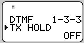
3 Press [UP]/[DWN] to switch the function ON (or OFF).

4 Press [OK] to complete the setting.
5 Press [MENU] to exit Menu mode.
AUTOMATIC DIALER
If you use the 10 dedicated memory channels to store DTMF numbers, you need not remember a long string of digits.
Storing a DTMF Number in Memory
Note: Audible DTMF tones from other transceivers near you (or from your own speaker) may be picked up by your microphone. If so, you may fail to correctly program a DTMF number.
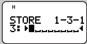
1 Press [MENU] to enter Menu mode.
2 Press [1], [3], [1] to select "1-3-1 (STORE)".
3 Press [UP]/[DWN] to select from channel 0 to 9.
4 Press [OK].
- The display for entering a memory name appears; the first digit blinks.
- To skip naming the channel, press [OK] again. You can jump to step 8.

5 Press [UP]/[DWN] to select a character.
- You can enter alphanumeric characters plus special ASCII characters.
6 Press [OK].
- The cursor moves to the next digit.
7 Repeat steps 5 and 6 to enter up to 8 digits.
- Pressing [OK] after selecting the 8th digit causes the cursor to move to the start of the next field.

- To complete programming the name after entering less than 8 digits, press [OK] twice.
Each press of [ESC] causes the cursor to move backward. - Pressing [A/B] deletes the digit at which the cursor is blinking.
8 Press the keys in sequence on the keypad to enter a DTMF number with up to 16 digits.
- You may press [UP]/[DWN] then [OK] to select each digit. Select a space if you want to put a pause.
9 Press [OK] to complete the programming.
10 Press [MENU] to exit Menu mode.
You can confirm the stored DTMF number by using steps 1 to 3.
You can also use the keypad to enter alphanumeric characters in step 5. For example, each press of [TNC] switches entry as A, B, C, a, b, c, then 2. Press [ENT] to switch among the special ASCII characters.
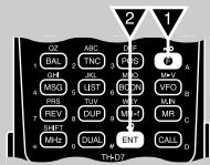
Transmitting a Stored DTMF Number
1 Press [PTT]+[MENU].
![KENWOOD TH-D7E - Press [PTT]+[MENU]. - 1](/content/2025/01/83300/images/9161e6ff8648b53883be7f7f8fd926672893f8c0ce2721b826162f2317f2f395.jpg)
2 Release only [MENU], then press [UP]/[DWN] to select the desired DTMF memory channel.
3 While still holding [PTT], press [MENU] again.
- The number stored in the channel scrolls across the display accompanied by DTMF tones from the speaker.
After transmission, the frequency display is restored.
If you need not confirm the memory channel contents, press [0] to [9] instead of [UP]/[DWN] in step 2 to select a channel number. The stored DTMF number will be immediately transmitted. You need not press [MENU] in step 3.
This transceiver allows you to switch the DTMF number transmission speed between Fast (default) and Slow. If a repeater cannot respond to the fast speed, access Menu 1-3-2 (TX SPEED) and select "Slow".
![KENWOOD TH-D7E - Press [PTT]+[MENU]. - 2](/content/2025/01/83300/images/bc0f95ee089067df6f6894cfc53c4b0319a8d012ade7ae2f2c1a053b9c2038dd.jpg)
You can also change pause duration stored in memory channels; the default is 500 msec. Access Menu 1-3-4 (PAUSE). The selectable pauses are 100, 250, 500, 750, 1000, 1500, and 2000 msec.
![KENWOOD TH-D7E - Press [PTT]+[MENU]. - 3](/content/2025/01/83300/images/374fc64c01428123f5ddd4f7bd8420f713258178578b8001a5e99710ea8f2c8a.jpg)
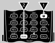
The optional SMC-33 or SMC-34 speaker microphone has 3 Programmable Function (PF) keys on its top. You can assign these keys the transceiver key functions that you frequently use. First connect the optional speaker microphone to this transceiver.
The defaults on the PF keys are as follows:
Mic [1]: [A/B]
Mic [2]: VFO/ Memory Recall mode switch
Mic [3]:[CALL]
1 Press Mic [1], [2], or [3] + POWER ON depending on which key you want to reprogram.
- "PF 1", "PF 2", or "PF 3" appears.
![KENWOOD TH-D7E - Press [PTT]+[MENU]. - 4](/content/2025/01/83300/images/75ffb3b658b8154e1e02556955b9a79cb68c014a39ae1ddf33c86cf193310348.jpg)
2 Press a key on the transceiver depending on the function you want to assign.
- Pressing a single key on the keypad assigns only the function printed on the top of the key.
- To assign the second function (printed in purple), press [F] first (ex. [F], [VFO]).
- Pressing the PTT switch assigns the function that switches between VFO and Memory Recall mode.
- Press [F], [0] to [9] to assign the functions that are selectable in Function Select mode.
- Pressing [ENT], [0] to [9] allows you to recall memory channel 0 to 9.
The key functions you can assign are shown below:
![KENWOOD TH-D7E - Press [PTT]+[MENU]. - 5](/content/2025/01/83300/images/88533b244e266c887ccffe11619c0567df4d323ddc4f28d30f7e0b6b9de0258b.jpg)
![KENWOOD TH-D7E - Press [PTT]+[MENU]. - 6](/content/2025/01/83300/images/e75e17946016a2820fed90885a3976356ebabde7b35963c8c7d45c7e4435c891.jpg)
Press [F] first.
| [0] | Memory Channel Lockout ON/ OFF | [5] | Offset freq. select |
| [1] | Tone ON/ OFF | [6] | AM/ FM switch¹ |
| [2] | Tone freq. select | [7] | Programmable VFO range select |
| [3] | CTCSS ON/ OFF | [8] | Freq. step size select |
| [4] | CTCSS freq. select | [9] | Memory name store |
1 TH-D7A only
Note:
Turn OFF the transceiver power before connecting the optional speaker microphone.
If the LOCK on the speaker microphone is ON, you cannot reprogram the Programmable Function keys.
AUXILIARY FUNCTIONS
DIRECT FREQUENCY ENTRY
If the desired operating frequency is far from the current frequency, using the keypad is the quickest way to change frequency.
1 Press [A/B] to select band A or B.
If necessary, press [F], [A/B] to recall the sub-band.
2 Press [VFO].
3 Press [ENT].
- The display for Direct Frequency Entry appears.

4 Press the numeric keys in sequence on the keypad.
- You can also enter a different band frequency from the current band. For example, you may enter a VHF frequency on band B where a UHF band is in use.
Note:
The 1 kHz and subsequent digits are corrected according to which key is pressed for the 1 kHz digit.
Entering a digit that is outside the allowable range causes the nearest digit within range to be displayed.
You cannot enter a frequency in a band which cannot be recalled on the current band.
If you press [VFO] while entering a frequency, the new data is accepted for the digits entered and the previous data remains unchanged for the digits not yet entered.
Previous freq.: 145.350 MHz

Note: The 1 kHz and subsequent digits may be corrected depending on combinations of the previous frequency and the current frequency step size.
If you press [ENT] while entering a frequency, the new data is accepted for the digits entered and 0 is programmed for the digits not yet entered.
Previous freq.: 145.350 MHz

To omit entry of the 100 MHz digit, enter for the 10 MHz and 1 MHz digits and press [MHz]. The previous data remains unchanged for the 100 MHz digit.
Previous freq.: 145.350 MHz

To omit entry of the 100 MHz and 10 MHz digits, enter for the 1 MHz digit and press [MHz]. The previous data remains unchanged for the 100 MHz and 10 MHz digits.
Previous freq.: 145.350 MHz

CHANGING FREQUENCY STEP SIZE
Choosing the correct step size is essential in order to select your exact receive frequency using the Tuning control or [UP]/[DWN]. The default step size on the VHF band is 5kHz (TH-D7A) or 12.5kHz (TH-D7E). The default on the UHF band is 25kHz no matter which market version.
1 Press [A/B] to select band A or B.
- If necessary, press [F], [A/B] to recall the sub-band.
2 Press [F], [8] to select "F-8 (STEP)".
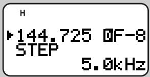
3 Press [UP]/[DWN] to select the desired step size.
- The selectable step sizes are 5, 6.25, 10, 12.5, 15, 20, 25, 30, 50, and 100kHz .
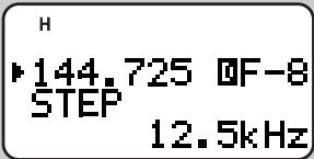
4 Press [OK] to complete the setting.
Note: Changing between step sizes may correct the displayed frequency. For example, if 144.995 MHz is displayed with a 5 kHz step size selected, changing to a 12.5 kHz step size corrects the displayed frequency to 144.9875 MHz.
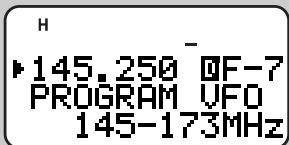
PROGRAMMABLE VFO
If you always check frequencies within a certain range, set upper and lower limits for frequencies that are selectable using the Tuning control or [UP]/[DWN]. For example, if you select 145 MHz for the lower limit and 146 MHz for the upper limit, the tunable range will be from 145.000 MHz to 146.995 MHz.
1 Press [A/B] to select band A or B.
- If necessary, press [F], [A/B] to recall the sub-band.
2 Press [VFO].
3 Press [F], [7] to select "F-7 (PROGRAM VFO)".
- The current lower frequency limit blinks.
4 Press [UP]/[DWN] to select the desired lower frequency limit.
5 Press [OK].
- The current upper frequency limit blinks.
6 Press [UP]/[DWN] to select the desired upper frequency limit.
7 Press [OK].
Note:
You cannot program the 100kHz and subsequent digits.
The exact 100kHz and subsequent digits of the upper limit depend on the frequency step size selected.
TONE ALERT
Tone Alert provides an audible alarm when signals are received on the frequency you are monitoring. In addition, it shows the number of hours and minutes elapsed after signals were received. If you use Tone Alert with CTCSS, it alarms only when a received CTCSS tone matches the tone you selected.
1 Press [A/B] to select band A or B.
If necessary, press [F], [A/B] to recall the sub-band.
2 Press [F], [ENT] to switch Tone Alert ON (or OFF).
- A bell icon appears when Tone Alert is ON.
- When a signal is received, an alarm sounds and the bell icon starts blinking.
- Pressing the PTT switch while the bell icon is blinking switches Tone Alert OFF.
- When 99 hours and 59 minutes pass after a signal is received, counting stops.
Each time a new signal is received, the time resets to 00.00.
Note:
While Tone Alert is ON, there is no speaker output when a signal is received. To hear receive audio, press and hold [MONI].
When Tone Alert is ON, APO does not turn the power OFF.
When Tone Alert is ON, you can use only the following functions:
- Lamp ON
Lamp Latch ON
Monitor
Band A/B Select
Squelch Level Select
BEEP ON/OFF
The transceiver beeps each time you press a key on the keypad. You can also switch this function OFF. Access Menu 1-5-3 (BEEP) and select "OFF". The default is "ALL".
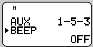
In Menu 1-5-3 you can also select "KEY" and "KEY+NEW DATA". Those settings are described in "APRS" sections {pages 63 and 77}.
ADJUSTING VOLUME BALANCE
While simultaneously receiving on 2 bands, you may sometimes feel that audio output on either band is too noisy. You can adjust the volume on the noisy band.
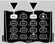
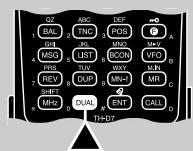
1 Press [BAL].
- The balance scale appears with a blinking cursor.
![KENWOOD TH-D7E - Press [BAL]. - 1](/content/2025/01/83300/images/e41daff0ea09b66e6ac8c5e5c8e12749eb5fccabf50b64ced844dd141e26ca2b.jpg)
![KENWOOD TH-D7E - Press [BAL]. - 2](/content/2025/01/83300/images/3b99acb5844fdf282398f8777b8b3c34cf86a601d044240a6141ce5acffadf8a.jpg)
2 Press [UP]/[DWN] to change the setting.
![KENWOOD TH-D7E - Press [UP]/[DWN] to change the setting. - 1](/content/2025/01/83300/images/8af9f2ea7f8dc3bb67af2770899fe376f8b3c12d5e87f1d3a422526a8b07b223.jpg)
Max: Maximum
Mute: Muted
Att: Attenuated
3 Press [OK] to complete the setting.
LAMP FUNCTION
You can illuminate the transceiver display and keypad by pressing [LAMP]. Approximately 5 seconds after releasing [LAMP], the light goes OFF if no other key is pressed. Pressing any key other than [LAMP] while the display is lit restarts the 5 second timer; pressing [LAMP] turns OFF the light immediately.
To latch the light ON, press [F], [LAMP]. The light remains ON until you press [F], [LAMP] again.
ADJUSTING DISPLAY CONTRAST
The display visibility changes depending on ambient conditions, for example between daytime and nighttime. When you find the display is not clear, use this function to select the optimum display contrast.
Access Menu 1-1-2 (CONTRAST) and select the contrast from 16 levels. The default is level 8.

BLANKING A BAND DISPLAY
If you have no plans to use band A or B, quit frequency display on the unused band. This saves power consumption and makes it simpler to read the information you need.
1 Press [A/B] to select band A or B.
2 Press [DUAL] to switch the function ON (or OFF).
- The non-current band will be blanked.

AUTOMATIC POWER OFF (APO)
Automatic Power Off is a background function that monitors whether any keys have been pressed, or whether any control has been turned. After the predetermined time passes with no operations, APO turns OFF the power. However, 1 minute before the power turns OFF, "APO" blinks and a series of warning tones sound.
Access Menu 1-2-2 (APO) and select 30 minutes (default), 60 minutes, or OFF.

Note:
If a signal is received while APO is ON, the timer begins counting again from 0.
The APO timer does not operate while Tone Alert or any scan is being used.
BATTERYSAVER
Battery Saver repeats switching the receive circuit ON and OFF at a certain interval when no signal is present and no key is pressed for approximately 10 seconds. This function becomes passive whenever a signal is received or any key is pressed.
Access Menu 1-2-1 (BAT Saver) to select the desired interval (power OFF duration). The default is 1.0 second.
- The selectable intervals are 0.2, 0.4, 0.6, 0.8, 1.0, 2.0, 3.0, 4.0, and 5.0 seconds plus OFF; selecting OFF switches the function OFF.

POWER-ONMESSAGE
Each time you switch the transceiver ON, "HELLO !!" appears and stays for approximately 1 second. You can program your favorite message in place of the factory default.
1 Press [MENU] to enter Menu mode.
2 Press [1], [1], [1] to select "1-1-1 (PWR ON MSG)".
- The display for entering a message appears; the first digit blinks.
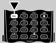

3 Press [UP]/[DWN] to select a character.
- You can enter alphanumeric characters plus special ASCII characters.
4 Press [OK].
- The cursor moves to the next digit.
5 Repeat steps 3 and 4 to enter up to 8 digits.
- Pressing [OK] after selecting the 8th digit completes the programming.
To complete programming the message after entering less than 8 digits, press [OK] twice.
Each press of [ESC] causes the cursor to move backward. - Pressing [A/B] deletes the digit at which the cursor is blinking.
6 Press [MENU] to exit Menu mode.
You can also use the keypad to enter alphanumeric characters in step 3. For example, each press of [TNC] switches entry as A, B, C, a, b, c, then 2. Press [DUAL] to switch 0 and space. Press [ENT] to switch among the special ASCII characters.
TRANSCEIVER LOCK
This function prevents accidental changes, or unauthorized individuals from changing the transceiver settings.
Press [F] (1 s) to switch the function ON (or OFF).
- A key icon appears when the function is ON.
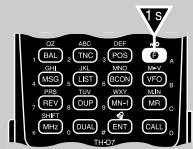
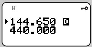
You may want to use the Tuning control or [UP]/[DWN] in Transceiver Lock mode. Access Menu 1-5-4 (TUNE ENABLE) and select "ON".

TX INHIBIT
You can disable the transmit function to prevent unauthorized individuals from transmitting, or to eliminate the risk of accidentally transmitting by yourself.
Access Menu 1-5-5 (TX INHIBIT) and select "ON".

- Pressing the PTT switch after switching TX Inhibit ON causes the transceiver to generate an error beep and display "TX INHIBIT!".
SWITCHING AM/FM MODE (TH-D7A ONLY)
This transceiver allows you to select AM or FM mode to receive on the 118 MHz band. The default is AM.
1 Select the 118 MHz band.
2 Press [F], [6] to switch between AM and FM.
- The 1 MHz decimal becomes long when AM mode is selected.
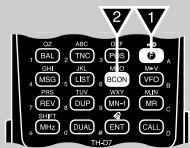
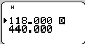
ADVANCED INTERCEPT POINT (AIP)
The VHF band is often crowded in urban areas. AIP helps eliminate interference and reduce audio distortion caused by intermodulation. You may use this function when operating on the VHF band. Access Menu 1-5-6 (TH-D7A) or Menu 1-5-8 (TH-D7E) and select "ON".

Note:
This transceiver does not allow you to use the AIP on the UHF band.
Switching ON the AIP also affects the VHF sub-band on band B.
SWITCHING TX DEVIATION (TH-D7E ONLY)
This transceiver is capable of switching the VHF band to narrow transmit deviation. Access Menu 1-5-7 (144Tx NARROW) and select "ON".

Note: When using the VHF band to transmit packets, do not switch the function ON.
Packet is a unit of data transmitted as a whole from one computer to another on a network. Packets can be transmitted on radio waves as well as on communications lines. Besides a transceiver and a computer, all you need is a terminal node controller (TNC). A TNC converts packets to audio tones and vice versa as one of its tasks. This transceiver has a built-in TNC.
A variety of packet applications developed by hams include packet bulletin board systems (PBBSs). PBBSs are created and maintained by volunteers called a System Operator (SysOp). You may access one of your local PBBSs to send e-mail, download a file, or obtain various useful information. Thousands of PBBSs, which have formed a worldwide network, relay e-mail to its intended destination around the world. First find out the call signs and frequencies used by your local PBBSs. Reference material for starting packet operation should be available at any store that handles Amateur Radio equipment.
Note:
Not all functions available via conventional TNCs are supported by the TNC built in this transceiver.
Packet operation, easily affected by transmit and receive conditions, requires a full-scale S-meter reading for reliable communication. When the S-meter reads less than maximum during 9600 bps operation, communication errors are frequent.
This transceiver is incapable of functioning as a digipeater.
"IND STA"indicates packets to be transmitted still remain in the buffer.
TH-D7E Only: When using the VHF band to transmit packets, do not select the narrow transmit deviation {page 51}.
PBBS
Mail box
Bulletin board
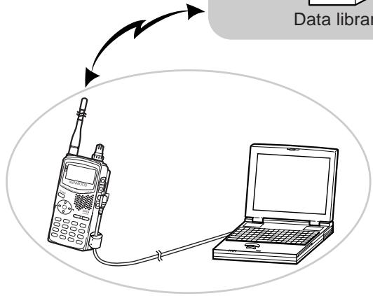
Data library
CONNECTING WITH A PERSONAL COMPUTER
You can use an optional PG-4W cable to connect the transceiver with a personal computer. For this cable, contact your authorized KENWOOD dealer.
Note: Turn OFF the transceiver power before making the connection.
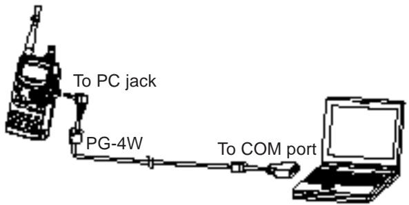
2.5 mm (1/10")
3-conductor plug
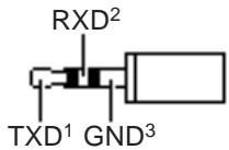
To RXD on PC
2 To TXD on PC
3 To GND on PC
DB-9 connector
| Pin No. | Pin Name |
| ⑤ | GND |
| ③ | TXD |
| ② | RXD |

Note: When the built-in TNC is ON, some internal frequency relationships may induce an internal heterodyne and cause the squelch to be opened unexpectedly. Shifting the interference will solve this problem. Press [TNC]+ POWER ON to access "BEAT SHIFT". Press [UP]/[DWN] to select "UPPER". Press [OK] to complete the setting. The default is "NORMAL".
OPERATING TNC
This transceiver has a built-in TNC which conforms to the AX.25 protocol. This protocol is used for communications between TNCs. The TNC accepts data from your personal computer and assembles it into packets. It then converts packets to audio tones which the transceiver can transmit. The TNC also takes audio tones from the transceiver, converts them to data for the computer, and checks for errors in the data.
The TNC mainly functions in Command or Converse mode. First learn the difference between these two modes.
Command mode
When you select Packet mode, the TNC enters this mode. A "cmd:" prompt appears on the computer screen. You can type commands from the computer keyboard to change the settings on the TNC. When in Converse mode, press [Ctrl] + [C] on the keyboard to restore the Command mode.
- Converse mode
The TNC enters this mode when a linkage with the target station is established. On the computer keyboard, type an appropriate command and if necessary a message, then press [Enter] or [Return]. What you type is converted into packets and transmitted over the air. When in Command mode, type CONVERSE to restore the Converse mode; you can also type CONV or K instead.
For the commands supported by the built-in TNC, see "TNC COMMANDS LIST" on page 99.
PREPARATION FLOW
The following steps should guide you to a good start of packet operation. The shaded steps indicate operations on your personal computer. First connect the transceiver to the personal computer {page 53}.
Note: You may switch Battery Saver OFF {page 49} to prevent the initial portion of a received packet from being missed.
Install an appropriate communications program on the personal computer.
- A variety of freeware or shareware programs can be obtained in various ways. Consult your reference material or other "packeteers".
2 Initiate the communications program and set the following parameters on the personal computer:
- Transfer rate (TNC < - Computer): 9600 bps
Data length: 8 bit - Stop bit: 1 bit
- Parity: Non
- Flow control: Xon/Xoff
3 Access Menu 1-4-1 to select band A or B as the data band {page 55}.
Press [TNC] to switch ON the TNC.
"TRC ] appears.
Press [TNC] again to enter Packet mode.
- "PACKET" also appears.
To select 9600 bps as the transfer rate from/to the target station, type HBAUD (or HB) 9600 and press [Enter] or [Return]. The default is 1200 bps.
- You must select the same transfer rate as the target station.
Type MYCALL (or MY) then your call sign (9 digits max.) and press [Enter] or [Return] to set your call sign on the TNC.
- You cannot use the default setting (NOCALL).
Tune to an appropriate frequency.
- First you may want to monitor packets which are transmitted among other stations. When packets are received, text appears and the computer screen scrolls.
To connect with the target station, type CONNECT (or C) then its call sign and press [Enter] or [Return].
- When a linkage is established, a message which informs you of it appears on the computer screen; on the transceiver display, “MN6_CN” appears.
- If packets from other stations keep your squelch open, adjust the squelch level in advance. The TNC cannot transmit in such a situation.
10 Send appropriate commands and, if necessary, messages to the target station via the TNC.
SELECTING DATA BAND
This transceiver is capable of receiving packet data on one band (data band) while receiving audio on another band. Select band A or B as the data band for receiving or transmitting packets. "B" indicates the current data band; the default is band A.
Access Menu 1-4-1 (DATA BAND) and select band A or B.
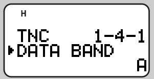
You can also select the method for inhibiting the built-in TNC from transmitting. Access Menu 1-4-2 (DCD SENSE) and select one of the two methods.

D BAND ONLY:
The TNC does not transmit when signals are present on the data band.
BOTH BANDS:
The TNC does not transmit when signals are present on the data band or another band.
FULL DUPLEX
This transceiver is also capable of simultaneously transmitting and receiving signals. So, it is possible to transmit audio on the current band while receiving packet data on another band (data band).
Press [DUP] to enter Full Duplex mode.
"DUP" appears.
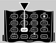
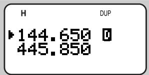
To exit Full Duplex mode, press [DUP] again.
Note:
You cannot use the Full Duplex function after recalling the VHF band on band B or blanking one band.
When using the Full Duplex function, connect an earphone to the SP jack. Using an earphone will prevent feedback that can cause the transceiver to emit a howling sound.
DX PacketClusters are networks which consist of nodes and stations who are interested in DXing and contesting. If one station finds a DX station on the air, he (or she) sends a notice to his (or her) node. Then this node passes the information to all its local stations besides another node. This transceiver can display received DX information and hold the latest information on up to 10 DX stations. Use this function to monitor the latest DX information in your local area. You cannot send DX information to a node, using the function.
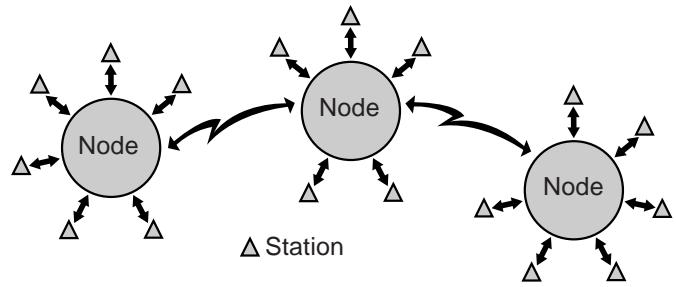
1 Access Menu 1-4-1 (DATA BAND) to select band A or B.
2 Tune to the frequency of the target PacketCluster node.
3 Press [TNC] to switch ON the TNC.
"100 _ ] appears.

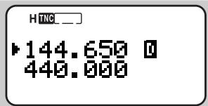
Each time new DX cluster data is received, the frequency display is interrupted to show information as below:
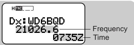
- The transceiver restores the frequency display after approximately 10 seconds pass or when you press any key.
- When duplicate DX cluster data is received, the frequency display is not interrupted. "dD" and a call sign will appear at the bottom of the display.
To scroll through up to 10 sets of DX information, press [LIST] twice, then press [UP]/[DWN].
- Press [OK] to access an attached comment (20 characters max.).

- Press [LIST] to restore the frequency display.
Note:
The information is cleared when the transceiver power is turned OFF.
This transceiver beeps each time it receives new or duplicate DX cluster data. You may access Menu 1-5-3 (BEEP) to change this setting. The default is "ALL". See the table on page 63.
Before tuning to a PacketCluster node, switch the APRS Beacon function OFF {page 74}; otherwise, unintentional APRS packet transmission will annoy PacketCluster nodes and stations.
SLOW-SCAN TELEVISION (SSTV) WITH VC-H1
Slow-scan Television (SSTV) is a popular application for transmitting still images over the air from one station to another. The VC-H1 is an optional portable unit which includes all requirements for SSTV; a slow-scan converter, a CCD camera, and a LCD monitor. You can transmit or receive full-color images just by connecting the VC-H1 to this transceiver. For further information on the VC-H1, see the instruction manual for the VC-H1.
From this transceiver you can enter and superimpose a message, an RSV report, and a call sign onto an image on the VC-H1 monitor. You can also select colors for those information.
Note: Use an optional PG-4V cable to connect the VC-H1 to this transceiver. For this cable, contact your authorized KENWOOD dealer. The cable that comes with the VC-H1 allows only image transfer from/ to other stations.
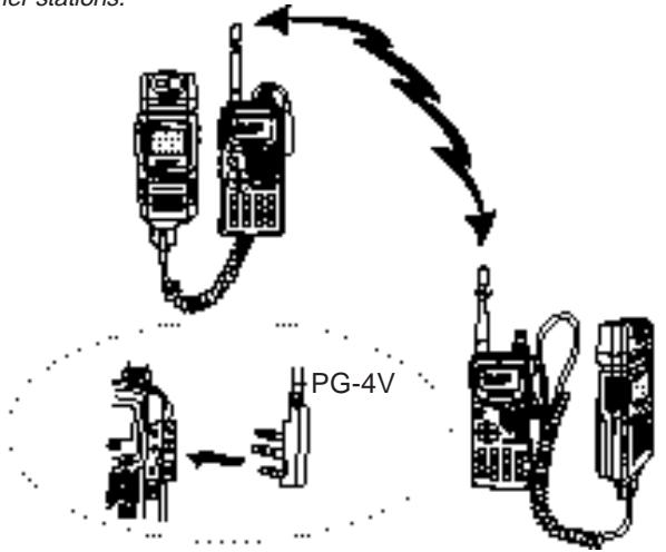
Use the following Menu Nos. to program information and select its color.
| 3-1 | MY CALL | Call sign (8 digits max.) |
| 3-2 | MY CALL COL | Color for call sign |
| 3-3 | MESSAGE | Message (9 digits max.) |
| 3-4 | MESSAGE COL | Color for message |
| 3-5 | RSV | RSV report (10 digits max.) |
| 3-6 | RSV COLOR | Color for RSV report |
In addition, you can use Menu 3-8 (TX MODE) to program a SSTV mode for the VC-H1. First connect the transceiver to the VC-H1 and switch ON both the transceiver and VC-H1. Press [MENU], [3], [8]. The SSTV mode currently set on the VC-H1 appears. Press [UP]/[DWN] to select the desired mode, then press [OK] to change the setting on the VC-H1. The selectable SSTV modes are as follows:
- Robot (color) 36
- Robot (color) 72
AVT90
AVT94
Scottie S1
Scottie S2
Martin M1
Martin M2
Fast FM
Note:
Switch OFF both the transceiver and VC-H1 before making the connection.
When the VC-H1 is too close to the transceiver, transmitting at high power using the provided antenna may cause malfunction. This is caused by unwanted feedback.
ENTERING CALL SIGN/MESSAGE/ RSV
Use the following procedures to enter a call sign, a message, or an RSV report. RSV stands for readability, signal strength, and video. If you receive a clear image free from noise, the RSV report should be 595.
Note: The only difference among Menus 3-1, 3-3, and 3-5 is the maximum number of digits that you can enter. So you may enter another message using Menu 3-5, for example.
1 Press [MENU] to enter Menu mode.
2 Press [3], [1] to select "3-1 (MY CALL)", or [3], [3] to select "3-3 (MESSAGE)", or [3], [5] to select "3-5 (RSV)".
- The display for entering characters appears; the first digit blinks.


3 Press [UP]/[DWN] to select a character.
- You can enter 0 to 9, A to Z, space,!, ?, -, and /.
4 Press [OK].
- The cursor moves to the next digit.
5 Repeat steps 3 and 4 to enter up to 8 digits (call sign), 9 digits (message), or 10 digits (RSV report).
- Pressing [OK] after selecting the last digit completes the programming.
- To complete programming after entering less than the maximum digits, press [OK] twice.
Each press of [ESC] causes the cursor to move backward. - Pressing [A/B] deletes the digit at which the cursor is blinking.
6 Press [MENU] to exit Menu mode.
You can also use the keypad to enter alphanumeric characters in step 3. For example, each press of [TNC] switches entry as A, B, C, then 2. Press [DUAL] to switch 0 and space. Press [ENT] to switch among the special ASCII characters.
| Readability | Video | ||
| 1 | Unreadable | 1 | Unrecognizable |
| 2 | Barely readable | 2 | Barely recognizable |
| 3 | Readable with considerable difficulty | 3 | Recognizable with considerable difficulty |
| 4 | Readable with practically no difficulty | 4 | Recognizable with practically no difficulty |
| 5 | Perfectly readable | 5 | Perfectly recognizable |
| Signal Strength | |||
| 1 | Faint signals barely perceptible | 6 | Good signals |
| 2 | Very weak signals | 7 | Moderately strong signals |
| 3 | Weak signals | 8 | Strong signals |
| 4 | Fair signals | 9 | Extremely strong signals |
| 5 | Fairly good signals | ||
SELECTING COLOR FOR CALL SIGN/MESSAGE/RSV
You can select white (default), black, blue, red, magenta, green, cyan, or yellow to color the call sign, message, or RSV report.
1 Press [MENU] to enter Menu mode.
2 Press [3], [2] to select "3-2 (MY CALL COL)", or [3], [4] to select "3-4 (MESSAGE COL)", or [3], [6] to select "3-6 (RSV COLOR)".
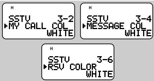
3 Press [UP]/[DWN] to select the color.
4 Press [OK] to complete the setting.
5 Press [MENU] to exit Menu mode.
EXECUTING SUPERIMPOSITION
After connecting the VC-H1 to this transceiver, use the following procedure to execute superimposition. First recall the desired image on the VC-H1.
1 Press [MENU] to enter Menu mode.
2 Press [3], [7] to select "3-7 (SUPERIMPOSE)".

- "EXECUTING" appears and data transfer starts.
3 Press [MENU] to exit Menu mode.
Note: Switch OFF both the transceiver and VC-H1 before making the connection.
VC-H1 CONTROL
If you have another transceiver that has the Tone function, you can use it as a remote control for the VC-H1. Transmit a subaudible tone from the remote control to this transceiver connected with the VC-H1 for more than 1 second. Then this transceiver causes the VC-H1 to capture an image, executes the superimposition, and transmits the image to the target station. You must select the same tone frequency on both transceivers; on this transceiver, program a CTCSS frequency {page 39}.
Note:
If you have made no entry for superimposition, superimposition will not be executed.
"EXECUTING" appears and blinks on this transceiver while a series of operations is in progress.

1 Press [MENU] to enter Menu mode.
2 Press [3], [9] to select "3-9 (VC SHUTTER)".
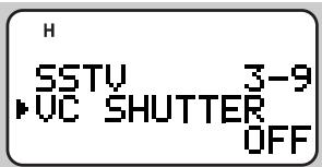
3 Press [UP]/[DWN] to switch the function ON (or OFF).
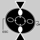

4 Press [OK] to complete the setting.
- Switching the function ON activates the CTCSS; "CT" appears.
5 Press [MENU] to exit Menu mode.
The following table concludes the settings you must confirm:
| TH-D7 and remote control | The current frequency is the same as the target station. |
| TH-D7 and remote control | The tone frequencies match 1. |
| Remote control | The Tone function is ON. |
| VC-H1 | The power is ON 2. |
1 For the TH-D7, use F-4 (CTCSS FREQ) {page 39}.
2 The camera and LCD monitor must not be left ON.
AUTOMATIC PACKET/ POSITION REPORTING SYSTEM
The Automatic Packet/ Position Reporting System (APRS) is a software program and registered trademark of Bob Bruninga, WB4APR. He has made packet communications much more exciting than before. This program allows you to track mobile stations on a map which you recall on a computer screen. Imagine seeing one mobile station moving on the map which can be scaled from .5 to 2000 miles. You also may be tracked on the computer screen of another station. Stations to be tracked must transmit beacons at certain intervals. To track other stations, you usually need a computer running the APRS, a transceiver, and a TNC. To have them track you, you also need a GPS receiver. It receives signals from the satellites to inform you of your current geographical position. GPS stands for Global Positioning System. The APRS interprets the National Marine Electronics Association (NMEA) data strings coming from the GPS receiver. For further information, consult Internet Web pages relating to the APRS. You may use one of the Internet search engines to find correct URLs.
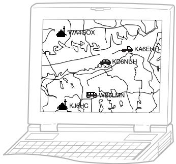
This transceiver includes a TNC and a program for dealing with data formats supported by the APRS. Its display shows information each time correct APRS data is received; you do not need a computer. It also allows you to manually enter position data (latitude/ longitude) to transmit; use this function if you do not have a GPS receiver. Besides position data this transceiver can receive or transmit the following information:
| Station icon | Weather reporting1 |
| Position comment | Status text |
| Moving speed2 | Moving direction2 |
1 Receive only
2 Can be transmitted only when using a GPS receiver.
This transceiver has a PC jack and GPS jack to connect with a personal computer and a GPS receiver. This manual, however, does not describe APRS communications which require these equipment.
Note:
Turn OFF the transceiver power before making the connections.
The GPS jack also accepts a 2.5 ~mm (1/10") 3-conductor plug. You may use the provided cable {page 1} to modify the cable end of your GPS receiver. The connection of each conductor (TXD/RXD/GND) is the same as the plug on the PG-4W {page 53}.
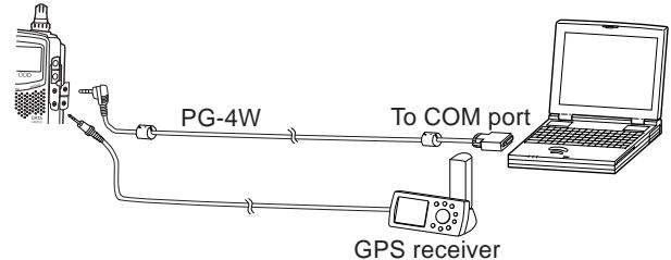
OPERATION FLOW
The following steps should guide you to a good start of APRS operation.
Press [TNC] to switch ON the TNC.
"NC]appears.
Access Menu 1-4-1 to select band A or B as the data band {page 55}.
On the data band select the same frequency as other stations in your group.
- You may tune to the frequency of an appropriate digipeater {page 72}.
Now you are ready to receive APRS data from other stations. Refer to "RECEIVING APRS DATA" {page 63}. To transmit your APRS data, proceed to step 4.
16
4 Access Menu 2-1 to program your call sign (9 digits max.) {page 66}.
If you have connected a GPS receiver, access Menu 2-2 and select "NMEA". The default is "NOT USED".
Access Menu 2-5 to select your station icon {page 67}.
Access Menu 2-3 to enter latitude and longitude data {page 68}.
Access Menu 2-4 to select from 8 position comments {page 69}.
9 If you want, access Menu 2-6 to enter status text using up to 20 alphanumeric characters {page 70}.
10 If you want, access Menu 2-A to program a group code {page 71}.
If necessary, access Menu 2-8 to program a packet path {page 72}.
12 Access Menu 2-9 to select the operation method for transmitting beacons {page 74}.
13 If you selected "PTT" or "AUTO" in step 12, access Menu 2-7 to select the interval for transmitting beacons {page 75}.
14 Press [BCON]. If you selected "PTT" in step 12, then press and release the PTT switch. See page 74.
Note: When using your personal computer, set the same communication parameters as Packet Operation {page 54}. On the transceiver, press [TNC] twice to enter Packet mode; "PACKET" should appear.
RECEIVING APRS DATA
Each time new APRS data is received, the frequency display is interrupted to show information as below:
H
KD6NUH Enroute to hamfest. Position comment (or status text)
- The received APRS data may include information on an object such as a hurricane or tornado. In this case, the name of the object appears instead of a call sign.
- The transceiver restores the frequency display after approximately 10 seconds pass or when you press any key.
Note: When you receive APRS data that you transmitted, the frequency display is not interrupted. "MY PACKET" will appear at the bottom of the display. This could happen when one or more digipeaters {page 72} are used.
If a received packet does not include new (or proper) APRS data, the frequency display is not interrupted. An indicator such as "dP" appears depending on the types of data. See the table.
HING 144.390 440.00dP KD6NUH
| Indicator | Meaning | What is Included? |
| dP | Duplicate position comment | Same comment as the previous one from the same station |
| dS | Duplicate status text | Status text already received |
| >P | Beyond position limit | Data from a station outside the selected range {page 75} |
| Q ?1 | Query | Request for sending information |
| ?? | Packet that cannot be decoded | |
1 The transceiver automatically transmits the appropriate information in approximately 2 minutes after receiving a request.
Note: The APRS programs for PCs have entry fields for a position comment and status text. The data entered to these two fields are transmitted as separate packets.
This transceiver beeps each time it receives new or duplicate APRS data. You may access Menu 1-5-3 (BEEP) to change this setting. The default is "ALL".
| Selections | Key Pressed | New APRS Data | Duplicate APRS Data |
| OFF | No beep | No beep | No beep |
| KEY | Beep | No beep | No beep |
| KEY+NEW DATA | Beep | Beep | No beep |
| ALL | Beep | Beep | Beep |
ACCESSING RECEIVED APRS DATA
This transceiver is capable of receiving and storing APRS data from up to 40 stations in memory. You can select the desired station and access the desired information, by switching the display.
1 Press [LIST].
- The display for selecting a station appears.
- The numbers beside the call signs indicate the order in which data is received. The data received last is assigned 1.
![KENWOOD TH-D7E - Press [LIST]. - 1](/content/2025/01/83300/images/87d79a225e578f90673e9bc59b6dcdc8fb2edbd3fa8456c98bd61617b6c823c4.jpg)
![KENWOOD TH-D7E - Press [LIST]. - 2](/content/2025/01/83300/images/c889e68bf71d9453e8be88fb8220e96a887450bfde1756319f39945332f76913.jpg)
2 Press [UP]/[DWN] to select the desired station.
![KENWOOD TH-D7E - Press [UP]/[DWN] to select the desired station. - 1](/content/2025/01/83300/images/49c468369d8bf418404c08a76852500ce733fc101f5049fc7a1b7f6a3af15a3a.jpg)
![KENWOOD TH-D7E - Press [UP]/[DWN] to select the desired station. - 2](/content/2025/01/83300/images/376997568bff7b94b668a8f36225adb785e4d2a53c58fe7b5f0532683c1c36d4.jpg)
3 Press [OK].
- The display for accessing the desired information appears.
![KENWOOD TH-D7E - Press [OK]. - 1](/content/2025/01/83300/images/9dddb96f265c9c61c3665fd609f43ac659643506b06cc6a0802781a7f31f141f.jpg)
![KENWOOD TH-D7E - Press [OK]. - 2](/content/2025/01/83300/images/8910d07906abc4ddf684f4e54ea76f6143461ec33249bcd8a0fb0b14a6eb8bc8.jpg)
4 Press [OK] repeatedly until you can access the desired information.
![KENWOOD TH-D7E - Press [OK]. - 3](/content/2025/01/83300/images/5fecc4d06e9bd9baa1a0667ffa3d50a7ade9717819f2e00d76aa1433ade41b2b.jpg)
![KENWOOD TH-D7E - Press [OK]. - 4](/content/2025/01/83300/images/513d2cf7546e62b9fbe795d6f87cbc45ee9fe704889d3291a80ca779099e183c.jpg)
- You may press [ESC] to restore the previous display.
5 Press [LIST] twice to restore the frequency display.
You may want to delete all information of the desired station. Press [A/B] instead of [OK] in step 3 or 4. "DELETE?" appears. Press [OK] to delete the information.
To delete the information of all stations, press [A/B] (1 s) in step 2. "DELETE ALL?" appears. Press [OK]. Then "ARE YOU OK?" appears. Press [OK] again to delete the information.
The types of information accessible in step 4 differ depending on the types of stations. For details, see the next page.
Note:
When data from the 41st station is received, the oldest data in memory is replaced by that data.
Each time new APRS data is received from the same station, the old data from that station (in memory) is replaced by new data.
When APRS data is received with a GPS receiver connected, included position data is sent to the receiver; the NMEA-0183 (\$GPWPL) format is used. This data is registered in the Waypoint List of the receiver; the right 6 digits of the call sign is used as a name (ex. for KJ6HC-3, J6HC-3).
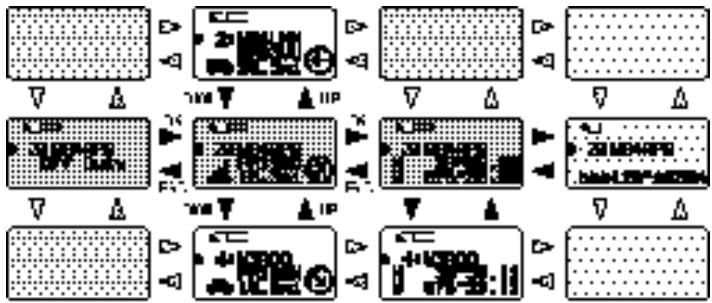
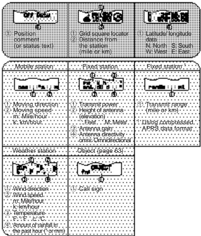
This transceiver is capable of displaying the following 18 icons as station IDs. When icon data other than these is received, the display will show an icon code such as /\ or .

Some icons may appear with characters if the received icon data includes them. The following are examples:

The following icons show the directions of stations relative to your position. For example, "®" indicates the other station is located at the northeast relative to your position.

0.0 to 9999 miles (or km) are shown for distances from other stations. "xxxxmi" (or "xxxxkm") is shown for distances over 9999 miles (or km).
On this transceiver the default units for distance and temperature are mile and ^ F . You can also change these units to kilometer and ^ C . Access Menu 2-C (UNIT) and select "km, ^ C ".
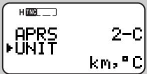
Note: You cannot separately change the units of distance and temperature.
PROGRAMMING A CALL SIGN
To transmit APRS data, first program your call sign using a maximum of 9 alphanumeric characters.
1 Press [MENU] to enter Menu mode.
2 Press [2], [1] to select "2-1 (MY CALL)".
- The display for entering characters appears; the first digit blinks. The default is "NOCALL".
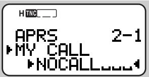
3 Press [UP]/[DWN] to select a character.
- You can enter 0 to 9, A to Z, and -.
4 Press [OK].
- The cursor moves to the next digit.
5 Repeat steps 3 and 4 to enter up to 9 digits.
- Pressing [OK] after selecting the 9th digit completes the programming.
- To complete programming after entering less than 9 digits, press [OK] twice.
Each press of [ESC] causes the cursor to move backward. - Pressing [A/B] deletes the digit at which the cursor is blinking.
6 Press [MENU] to exit Menu mode.
You can also use the keypad to enter alphanumeric characters in step 3. For example, each press of [TNC] switches entry as A, B, C, then 2. Press [ENT] to enter -.
Note: Unless you program a call sign, you cannot transmit APRS data.
SELECTING YOUR STATION ICON
Select an icon which will be displayed on the monitors of other stations as your ID. You may select an icon depending on your current location.
1 Press [MENU] to enter Menu mode.
2 Press [2], [5] to select "2-5 (ICON)".

3 Press [UP]/[DWN] to select from 15 icons plus "OTHERS".
- The following 15 icons are selectable:

4 Press [OK].
5 Press [MENU] to exit Menu mode.
| W | KENWOOD | SSTV | Triangle | ||
| Jogger | Aircraft | Jeep | |||
| Home | Boat | Recreation vehicle | |||
| Portable (tent) | Car | Truck | |||
| Yacht | Motorcycle | Van |
APRS supports approximately 200 icons. It allows users to select each icon by specifying a combination of two ASCII codes, for example, / and !. One is a symbol code, and the other is a table identification code (either / or ). If you select "OTHERS" in step 3, you can proceed to steps for specifying combinations of two codes. This method is described in the separate manual (document file) that comes with an optional PG-4W cable. This manual describes the APRS in further details.
ENTERING LATITUDE/ LONGITUDE DATA
This transceiver allows you to manually enter latitude and longitude data to transmit to other stations.
1 Press [MENU] to enter Menu mode.
- You may press [POS] instead. Then you can skip step 2.
2 Press [2], [3] to select "2-3 (My Pos)".
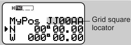
3 Press [UP]/[DWN] to switch between north latitude (default) and south latitude.
4 Press [OK].
The degree digits blink.
5 Press [UP]/[DWN] to select data for degrees.
6 Press [OK].
The minute digits blink.
7 Repeat steps 5 and 6 to select data for minutes (down to one hundredth digit).
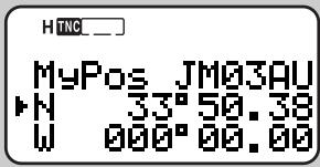
8 Press [UP]/[DWN] to switch between west longitude (default) and east longitude.
9 Press [OK].
The degree digits blink.
10 Press [UP]/[DWN] to select data for degrees.
11 Press [OK].
The minute digits blink.
12 Repeat steps 10 and 11 to select data for minutes (down to one hundredth digit).
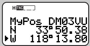
13 Press [MENU] to exit Menu mode.
Note:
If have selected "NMEA" in Menu 2-2, pressing [POS] does not allow you to access the display for entering latitude/ longitude data. The position data received via the GPS receiver most lately will be displayed.
If using a GPS receiver, you can also copy the measured data to the position entry display for Menu 2-3. Press [POS] to display the measured data, then press [OK]. "COPY to MENU?" appears. Press [OK] again.
Grid squares were developed to shortly identify locations anywhere on the Earth. The world is first divided into 324 areas (AA RR) called "fields". Each field is then divided into 100 "squares" (00 99). Each square is further divided into 576 "sub-squares" (AA XX). The world is eventually divided into 18, 662, 400 grids; each grid is expressed with 6 digits.
SELECTING A POSITION COMMENT
The APRS data which you transmit always include one of the 8 predetermined position comments. Select an appropriate comment depending on your situation.
1 Press [MENU] to enter Menu mode.
2 Press [2], [4] to select "2-4 (POS COMMENT)".
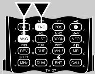

3 Press [UP]/[DWN] to select the desired comment.
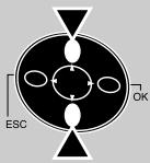

4 Press [OK] to complete the setting.
5 Press [MENU] to exit Menu mode.
The selectable comments are listed below:
| Off Duty (default) | Committed |
| En Route | Special 1 |
| In Service | Priority 1 |
| Returning | Emergency! 2 |
1 Selecting these comments will highlight your station on all other APRS computer displays.
2 Select this comment only when absolutely necessary. You will activate alarms in all monitoring APRS stations.
ENTERING STATUS TEXT
You can also transmit any comment (status text) with the latitude/ longitude data. If you want, enter a desired comment using a maximum of 20 alphanumeric characters.
Note: Attaching a long comment can double the size and length of the packet. Enter a comment only if necessary.
1 Press [MENU] to enter Menu mode.
2 Press [2], [6] to select "2-6 (STATUS TEXT)".
- The display for entering a comment appears; the first digit blinks.


3 Press [UP]/[DWN] to select a character.
- You can enter alphanumeric characters plus special ASCII characters.
4 Press [OK].
- The cursor moves to the next digit.
5 Repeat steps 3 and 4 to enter up to 20 digits.
- Pressing [OK] after selecting the 20th digit completes the programming.
To complete programming a comment after entering less than 20 digits, press [OK] twice.
Each press of [ESC] causes the cursor to move backward. - Pressing [A/B] deletes the digit at which the cursor is blinking.
6 Press [MENU] to exit Menu mode.
You can also use the keypad to enter alphanumeric characters in step 3. For example, each press of [TNC] switches entry as A, B, C, a, b, c, then 2. Press [DUAL] to switch 0 and space. Press [ENT] to switch among the special ASCII characters.
PROGRAMMING A GROUP CODE
Using a group code relieves you from receiving unwanted packets. The APRS on this transceiver supports the following three types of group codes.
All calls:
Program a 6-digit code that always starts with AP. You will receive all APRS packets which include AP in group codes. It does not matter whether or not the subsequent 4 digits match. The default on this transceiver is APK001; K001 stands for KENWOOD Ver.1.
Note: APRS packets, which are generated via various methods, include various codes instead of group codes. Using "All calls" allows you to receive packets which include the following codes.
| GPS | SYM | QST | CQ | BEACON |
| ALL | SKYWRN | ID | SPCL |
Special:
Enter "SPCL". You will receive only APRS packets that include SPCL as a group code. This code is generally programmed by all stations at a special event.
Alternate net:
Program any other code with a maximum of 6 digits. You will receive only APRS packets that include the exact same code. In order to reject other packets, this code should not include characters specified by the above two types.
Note: Menu 2-A allows you to enter up to 9 digits (not 6 digits) because of possible future enhancement of the group code system.
1 Press [MENU] to enter Menu mode.
2 Press [2], [A] to select "2-A (UNPROTOCOL)".
- The display for entering characters appears; the first digit blinks. The default is APK001 (All calls).
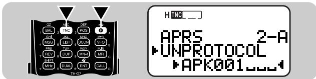
3 Press [UP]/[DWN] to select a character.
- You can enter 0 to 9, A to Z, and -.
4 Press [OK].
- The cursor moves to the next digit.
5 Repeat steps 3 and 4 to enter up to 9 digits.
- Pressing [OK] after selecting the 9th digit completes the programming.
To complete programming after entering less than 9 digits, press [OK] twice.
Each press of [ESC] causes the cursor to move backward. - Pressing [A/B] deletes the digit at which the cursor is blinking.
6 Press [MENU] to exit Menu mode.
You can also use the keypad to enter alphanumeric characters in step 3. For example, each press of [TNC] switches entry as A, B, C, then 2. Press [ENT] to enter
PROGRAMMING A PACKET PATH
A packet path specifies how APRS data should be transferred via one or more repeaters. A repeater, which is used for packet transfer, is commonly called a digipeater. This came from a digital repeater. A digipeater is usually located on a mountain top or high building. Unlike a voice repeater, it operates on a simplex frequency. Each volunteer who installs a digipeater declares his (or her) digipeater to be a "wide" type or "relay" type. Generally a wide-type digipeater transmits packets over much greater distances than a relay-type one.
The APRS supports various methods for specifying a packet path. Some of those methods are described on the next page. This transceiver allows you to edit a path using a maximum of 32 alphanumeric characters. The default is "RELAY,WIDE" that is one of the common settings. A comma must be put between each parameter.
Note: This transceiver is incapable of functioning as a digipeater.
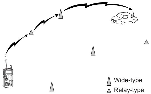
1 Press [MENU] to enter Menu mode.
2 Press [2], [8] to select "2-8 (PACKET PATH)".
- The display for entering characters appears; the first digit blinks.
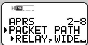
3 Press [UP]/[DWN] to select a character.
- You can enter 0 to 9, A to Z, , (comma), and -.
4 Press [OK].
- The cursor moves to the next digit.
5 Repeat steps 3 and 4 to enter up to 32 digits.
- Pressing [OK] after selecting the 32nd digit completes the programming.
- To complete programming after entering less than 32 digits, press [OK] twice.
Each press of [ESC] causes the cursor to move backward. - Pressing [A/B] deletes the digit at which the cursor is blinking.
6 Press [MENU] to exit Menu mode.
You can also use the keypad to enter alphanumeric characters in step 3. For example, each press of [TNC] switches entry as A, B, C, then 2. Press [ENT] to switch between , and - .
Let us describe four basic methods for editing a packet path.
Method 1 (Specific path):
Program the call signs of one or more digipeaters in the sequence of transfer relay; ex. "KD6ZZV,KF6RJZ".
Method 2 (Generic path):
Program "RELAY" and/or "WIDE"; ex. "RELAY,WIDE". In this example, APRS data is transferred to any relay-type digipeater near your position first, then to any wide-type digipeater. You can also program more than one "WIDE". If you enter "WIDE,WIDE" for example, APRS data will be transferred to any wide-type near your position first, then to another wide-type. This method relieves you from specifying the call signs of digipeaters.
Method 3 (WIDEN-N path):
Program "WIDEN-N", where both Ns indicate the number of wide-type digipeaters to be used for relay. If you enter "WIDE3-3" for example, APRS data will be relayed by three digipeaters in any direction.
Note: This method is supported only by advanced APRS networks.
Method 4 (SSID path):
Program a single number 1 to 15. You can easily specify the number of digipeaters that will be used for relay. You can also specify which directions of digipeaters relative to your position will be used. See the table.
Note: This method is supported only by advanced APRS networks.
| Parameter | Number of digipeaters | Direction |
| 1 | 1 | All |
| 2 | 2 | All |
| 3 | 3 | All |
| 4 | 4 | All |
| 5 | 5 | All |
| 6 | 6 | All |
| 7 | 7 | All |
| 8 | 2 (or more)1 | North |
| 9 | 2 (or more)1 | South |
| 10 | 2 (or more)1 | East |
| 11 | 2 (or more)1 | West |
| 12 | Many2 | North |
| 13 | Many2 | South |
| 14 | Many2 | East |
| 15 | Many2 | West |
1 The first digipeater which receives your APRS data specifies the entire route to the destination before forwarding; often 2 digipeaters are used in total.
2 The digipeater which receives your APRS data specifies the call sign of the next digipeater before forwarding. This is repeated until your APRS data reaches the destination.
SELECTING BEACON TRANSMIT METHOD
Select the operation method for transmitting APRS data. The table concludes how operations differ depending on the selection:
1 Press [MENU] to enter Menu mode.
2 Press [2], [9] to select "2-9 (DATA TX)".
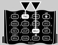
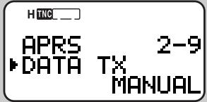
3 Press [UP]/[DWN] to select Manual (default), PTT, or Auto.
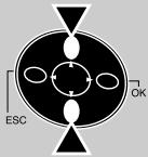
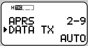
16
4 Press [OK] to complete the setting.
5 Press [MENU] to exit Menu mode.
| MANUAL | Each press of [BCON] transmits the APRS data. |
| PTT | 1 Press [BCON] to switch the function ON. ·“BCON” appears and blinks. 2 Press and hold the PTT switch, then speak into the microphone. 3 Release the PTT switch. ·Releasing the switch transmits the APRS data. ·You cannot retransmit the APRS data unless the time selected in Menu 2-7 (TX INTERVAL) passes. Wait until “BCON” starts blinking to indicate transmitting is ready. 4 To switch the function OFF, press [BCON] again. |
| AUTO | 1 Press [BCON] to switch the function ON. ·“BCON” appears. ·Switching the function ON transmits the APRS data once. After that, APRS data is automatically transmitted at intervals of the period selected in Menu 2-7 (TX INTERVAL). 2 To switch the function OFF, press [BCON] again. |
SELECTING BEACON TRANSMIT INTERVAL
Select an interval for automatically transmitting APRS data. The default is 5 minutes.
1 Press [MENU] to enter Menu mode.
2 Press [2], [7] to select "2-7 (TX INTERVAL)".
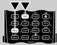
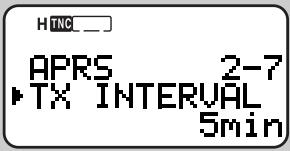
3 Press [UP]/[DWN] to select the desired interval.
- The selectable intervals are .5, 1, 2, 3, 5, 10, 20, and 30 minutes.
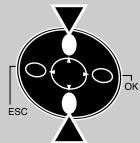
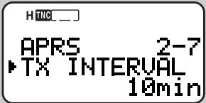
4 Press [OK] to complete the setting.
5 Press [MENU] to exit Menu mode.
Note:
With "AUTO" in Menu 2-9 and Beacon ON, pressing [OK] in step 4 causes the APRS data to be immediately transmitted. After that, the APRS data is transmitted at intervals of the selected period.
While signals are present, APRS data is not transmitted after the interval. Approximately 2 seconds after signals drop, transmitting is executed.
RESTRICTING RECEPTION OF APRS DATA
If APRS is popular in your country, you may receive too many APRS packets for a short period. If this disturbs your APRS activities, specify a distance from your location. You will not receive APRS data from stations beyond this distance.
1 Press [MENU] to enter Menu mode.
2 Press [2], [B] to select "2-B (POS LIMIT)"
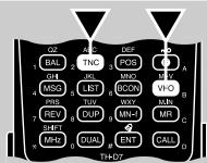
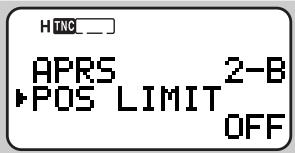
3 Press [UP]/[DWN] to select the desired distance.
- The selectable range is from 10 to 2500 in steps of 10, plus OFF. The unit is mile or kilometer depending on the selection in Menu 2-C (UNIT) {page 65}.
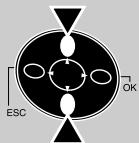
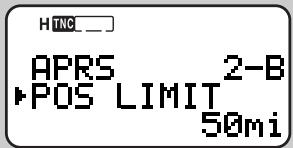
4 Press [OK] to complete the setting.
5 Press [MENU] to exit Menu mode.
The APRS_ ® supports a function for transmitting and receiving a message independent of position reports. You can transmit a message to a single station only or a bulletin to all other stations in your group. If you specify a station, the entered message is transmitted up to 5 times until a reception acknowledgment is returned.
Each message which you transmit can consist of up to 45 alphanumeric characters. A maximum of 16 incoming or outgoing messages can be held in the message memory.
OPERATION FLOW
The following steps should guide you to a good start of APRS Message operation.
Press [TNC] to switch ON the TNC.
- "TAC _]" appears.
Access Menu 1-4-1 to select band A or B as the data band {page 55}.
On the data band select the same frequency as other stations in your group.
- You may tune to the frequency of an appropriate digipeater {page 72}.
Access Menu 2-1 to program your call sign (9 digits max.) {page 66}.
Now you are ready to receive a message from other stations. Refer to "RECEIVING AMESSAGE" {page 77}. To transmit a message, proceed to step 5.
If necessary, access Menu 2-8 to program a packet path {page 72}.
Enter a message (or bulletin) using up to 45 alphanumeric characters {page 79}.
Completing step ⑥ causes the transceiver to automatically transmit the message (or bulletin). If you send a message (not a bulletin), a reception acknowledgment should be returned; "ack" appears.
RECEIVING AMESSAGE
Each time a proper message is received, the frequency display is interrupted to show information as below:

- The display shows only the first 24 characters of the message.
- The transceiver restores the frequency display after approximately 10 seconds pass or when you press any key.
- "□" appears and stays at the bottom left of the display until you use the List function {page 78}.
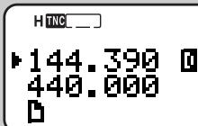
The following indicators appear depending on types of received messages:
| □ 0~91 | A personal message to you |
| 0~91, A~Z1 | A bulletin to all stations in your group |
| ! | A report by the National Weather Service |
| * | Reception acknowledgment to your message |
Sequence of message (or bulletin) packets from the same station
When a duplicate message from the same station is received, an error beep sounds. In addition, "dM" and a call sign appear on the display.
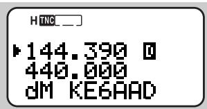
- When a message to other stations is received, "oM" appears at the bottom left of the display.
This transceiver beeps each time it receives a new or duplicate message. You may access Menu 1-5-3 (BEEP) to change this setting. The default is "ALL".
| Selections | Key Pressed | New Message | Duplicate Message |
| OFF | No beep | No beep | No beep |
| KEY | Beep | No beep | No beep |
| KEY+NEW DATA | Beep | Beep | No beep |
| ALL | Beep | Beep | Beep |
Note:
This transceiver allows you to receive a message also when the SSID does not match. However, it will not return a reception acknowledgment.
When a message addressed to you is received, the transceiver display and keypad are illuminated. If you do not press any key in approximately 5 seconds, the light goes off.
ACCESSING RECEIVED APRS MESSAGES
This transceiver is capable of storing a maximum of 16 messages in memory. You can access the desired massage by switching the display.
1 Press [MSG].
2 Press [UP]/[DWN] to select "LIST".
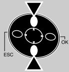
HING
LIST
INPUT
TRANSMIT
3 Press [OK].
4 Press [UP]/[DWN] to select the desired station.
- Press [OK] to see the 25th and subsequent digits of the message.
- “ 串 ” indicates the end of the message.
5 Press [ESC] twice to restore the frequency display.
Pressing [MSG] in step 4 allows you to enter a message to be returned to the station. You can skip steps 1 to 6 in "ENTERING AMESSAGE" {page 79}.
17
Note:
The dedicated memory is used for storing both received messages and messages for transmitting. Receiving a new message when the memory is full causes the oldest message to be deleted. A message not yet transmitted 5 times may be unexpectedly deleted. If “□” stays at the bottom left of the display when memory is full, a new message does not replace the oldest message. This transceiver returns a reject command and shows “rM” and a call sign at the bottom of the display.
A message already transmitted can be easily sent to the same station. Select the message in step 4 and press [MSG]. The call sign and message are copied to the recalled entry display {page 79}.
Besides the call sign and message, the display will show the following types of information:
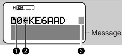
| 1 Message Type | |
| ☐ 0~9 1 | A personal message to you |
| 0~9 1, A~Z 1 | A bulletin to all stations in your group |
| ! | A report by the National Weather Service |
| 2 RX or TX? | |
| <- | A received message |
| -> 2 | A message for transmitting |
| 3 Status | |
| + 2 | A message (or bulletin) not yet transmitted 5 times |
| * 2 | A message for which a reception acknowledgment was returned |
| . 2 | A message (or bulletin) transmitted 5 times (For a message, a reception acknowledgment was not returned.) |
Sequence of message (or bulletin) packets from the same station
2 These indicators appear for outgoing messages {page 80}.
ENTERING AMESSAGE
You can enter a message or bulletin using up to 45 alphanumeric characters. To transmit a message, first enter the call sign of the target station. To transmit a bulletin to all other stations in your group, enter "BLN *" as the call sign; where * must be any single alphanumeric character. When the length of your bulletin exceeds 45 digits, you may transmit more than one packet to send the entire bulletin. You can use * to indicate the sequence of the bulletin portions. For example, you may program "BLN0" (or "BLNA") to send the first packet, then "BLN1" (or "BLNB") to send the second packet.
1 Press [MSG].
2 Press [UP]/[DWN] to select "INPUT".
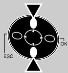
HING LIST INPUT TRANSMIT
3 Press [OK].
- The display for entering a call sign appears; the first digit blinks.
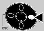
HING MSG INPUT TO:
4 Press [UP]/[DWN] to select a character.
-
You can enter alphanumeric characters plus special ASCII characters.
-
You may use the keypad. For example, each press of [TNC] switches entry as A, B, C, then 2. Press [ENT] to enter - .
5 Press [OK].
- The cursor moves to the next digit.
6 Repeat steps 4 and 5 to enter up to 9 digits.
- Pressing [OK] after selecting the 9th digit causes the cursor to move to the start of the next field.

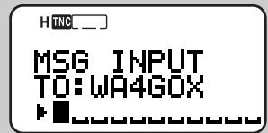
- To complete programming the call sign after entering less than 9 digits, press [OK] twice.
Each press of [ESC] causes the cursor to move backward. - Pressing [A/B] deletes the digit at which the cursor is blinking.
7 Press [UP]/[DWN], then [OK] to select the first digit of a message (or bulletin).
- You may use the keypad. For example, each press of [TNC] switches entry as A, B, C, a, b, c, then 2. Press [ENT] to switch among the special ASCII characters.
8 Repeat step 7 to enter a message (or bulletin) with up to 45 digits.
- To complete programming after entering less than 45 digits, press [OK] twice.
- Completing step 8 causes the transceiver to automatically transmit the message (or bulletin). If you send a message (not a bulletin), a reception acknowledgment should be returned; "ack" appears.
TRANSMITTING AMESSAGE
When entry of a message (or bulletin) is completed, this transceiver automatically transmits it 5 times (max.) at intervals of 1 minute.
For a message:
The transceiver repeats transmitting up to 5 times until a reception acknowledgment is returned.

For a bulletin:
The transceiver always repeat transmitting 5 times. A reception acknowledgment is not returned.
The table given on page 78 also shows indicators that appear for outgoing messages (or bulletins). “+” is assigned to messages (or bulletins) that have not yet been transmitted 5 times. You can also manually transmit all of those regardless of the 5-minute timer.
1 Press [MSG].
2 Press [UP]/[DWN] to select "TRANSMIT".
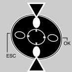

3 Press [OK] to start transmitting.
After transmission, the frequency display is restored.
WIRELESS REMOTE CONTROL (TH-D7A ONLY)
If you also have a KENWOOD multi-band mobile transceiver, you can control one of its bands by sending DTMF tones from this handy transceiver. You will find this function useful when you want to control your mobile transceiver from a location outside your vehicle.
Note:
You can remotely control only the mobile transceivers that have both the DTSS and Remote Control functions.
The FCC rules permit you to send control codes only on the 440 MHz band.
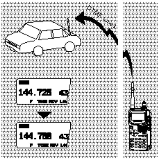
PREPARATION
Let us assume the VHF band of the mobile transceiver will be controlled.
On the handy transceiver:
1 Press [PTT]+[VFO]+ POWER ON.
- The current secret access code number appears. The default is 000.

2 Press a numeric key 0 to 9 to enter a 3-digit secret number.
- You can also press [UP]/[DWN] to select each digit. Press [OK] (or [ESC]) to move the cursor to the next (or previous) digit.
3 Press [OK] to complete the setting.
4 Select the UHF band.
5 Select the transmit frequency.
6 Turn the transceiver power OFF.
7 Press [PTT]+[MR]+ POWER ON.
- The transceiver enters Remote Control mode. "MOBILE CTRL" appears.
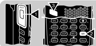

- To exit Remote control mode, repeat steps 6 and 7.
On the mobile transceiver:
8 Program the DTSS code on the UHF band as the secret number.
- Select the same number as you selected in step 2.
- For the programming method, refer to the instruction manual for the mobile transceiver.
9 Select the receive frequency on the UHF band.
- Mate this frequency with the transmit frequency on the handy transceiver.
10 Make the transceiver enter Remote Control mode.
- For the method, refer to the instruction manual for the mobile transceiver. If not described, consult your authorized KENWOOD dealer, customer service, or service center.
CONTROL OPERATION
When in Remote Control mode, the keys of the handy transceiver will function as below. Each time you press the desired key, the handy transceiver will automatically enter transmit mode and send the corresponding command to the mobile transceiver.
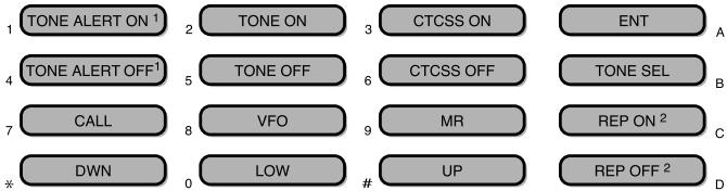
TM-V7A: REV ON/ OFF
Switches Cross-band Repeater ON/ OFF if the mobile transceiver has the function.
To change the transmit/ receive frequency:
$$ \begin{array}{l} \left([ \mathrm {V F O} ] \Rightarrow [ \mathrm {E N T} ] \Rightarrow [ 0 ] \sim [ 9 ] \text {(e n t e r t h e n e c e s s a r y d i g i t s)} \right. \ \Rightarrow [ \mathrm {E N T} ]) \text {o r} \left([ \mathrm {V F O} ] \Rightarrow [ \mathrm {U P} ] / [ \mathrm {D W N} ]\right) \end{array} $$
To recall a memory channel:
$$ \begin{array}{l} \left([ M R ] \Rightarrow [ E N T ] \Rightarrow [ 0 ] \sim [ 9 ] (e n t e r t h e n e c e n s a r y d i g i t s) \Rightarrow \right. \ \left[ E N T ]\right) o r \left(\left[ M R ] \Rightarrow [ U P ] / [ D W N ]\right) \right. \end{array} $$
To change the tone (or CTCSS) frequency:
$$ \begin{array}{l} \text {(T O N E S E L ]} \Rightarrow [ 0 ] \sim [ 9 ] \text {(e n t e r 2 d i g i t s ; e x . [ 0 ] , [ 5 ])} \Rightarrow \ \text {[ T O N E S E L ])} \end{array} $$
- Use Nos. 01 to 38 shown in the table in page 22.
- Your mobile transceiver may require you to first activate the Tone or CTCSS function. It may also allow you to program a separate tone and CTCSS frequency. Check the instruction manual for the mobile transceiver.
The Sky Command II allows remote control of a TS-570D, TS-570S, or TS-870S HF transceiver. This system requires two TH-D7As and the optional cables which connect one TH-D7A to the HF transceiver. You will use one TH-D7A as both a remote control and speaker microphone. This TH-D7A is called "Commander". The TH-D7 connected with the HF transceiver is called "Transporter". It will function as an interface between the Commander and the HF transceiver. The Sky Command System allows you, for example, to watch for and hunt DX while working around the house, or to operate the HF transceiver while relaxing in the living room or patio, instead of in the shack.
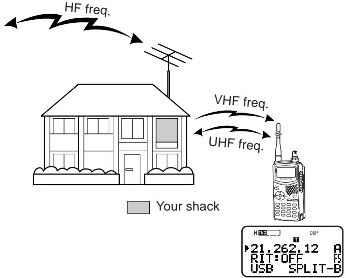
Both the Commander and Transporter use Full Duplex function to transfer audio and commands as below:
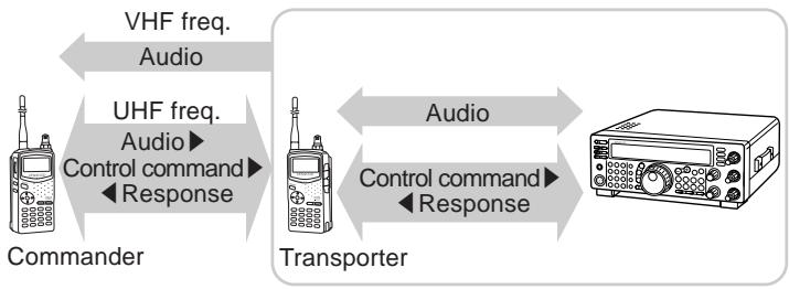
CONNECTING THE TRANSPORTER WITH THE HF TRANSCEIVER
You can use the optional cables (PG-4R) to connect the Transporter with the HF transceiver. For these cables, contact your authorized KENWOOD dealer.
Note:
Switch OFF both the Transporter and HF transceiver before making the connection.
The Transporter automatically transmits its call sign in Morse at regular intervals because of the legal requirement; therefore, transmit sidetone must be output from the HF transceiver. On TS-570D or TS-570S, do not select "OFF" in Menu 21. On TS-870S, use the MONI control to adjust the volume of sidetone.
When the Transporter is too close to the HF transceiver, unwanted feedback may cause malfunction.
Do not share a regulated power supply between the Transporter and the HF transceiver. Unwanted feedback may cause malfunction.

You need not worry about which end goes to which side
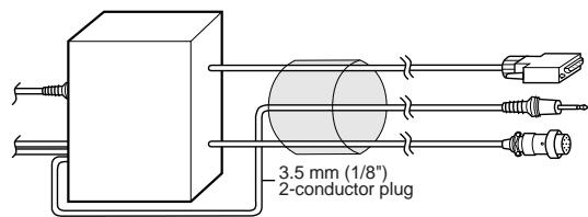
HF transceiver
COM connector
EXT SP jack
MIC connector

You may install appropriate noise filters at the shown positions to prevent unwanted feedback from causing malfunction.
PREPARATION FLOW
The following steps should guide you to a good start of Sky Command operation. First connect the Transporter to the HF transceiver {page 84}.
1 On the Commander and Transporter Select the same VHF and UHF frequencies.
On the Commander Access Menu 4-1 to program a call sign (9 digits max.) for the Commander {page 86}.
- You may enter your exact call sign; ex. WD6BQD.
On the Commander Access Menu 4-2 to program a call sign (9 digits max.) for the Transporter {page 86}.
- This call sign must be different from the one for the Commander. So you may add SSID characters; ex. WD6BQD-1.
On the Transporter Access Menu 4-1 to program the same call sign as you
entered in step 2 {page 86}.
On the Transporter Access Menu 4-2 to program the same call sign as you
entered in step 3 {page 86}.
On the Commander Access Menu 4-3 and select and Transporter the tone frequency {page 86}.
- Select the same tone frequency on both transceivers.
- For the selectable frequencies, see the table given on page 22.
7 On the Commander Access Menu 4-4 and select "COMMANDER".
- "PUSH [0] KEY TO START COMMANDER!!" appears.
On the Transporter Access Menu 4-4 and select "TRANSPORTER".
- "TRANSPORTER" appears.
Now the Commander and Transporter are in Sky Command mode. For operations in this mode, see "CONTROL OPERATION" on page 87. First switch ON the HF transceiver and press [SYNC] on the Commander. To exit the Sky Command mode, access Menu 4-4 and select "OFF"; press [F], [1] to switch the Tone function OFF, and press [DUP] to exit Full Duplex mode.
Note:
Unless you program call signs, you cannot select "COMMANDER" or "TRANSPORTER" using Menu 4-4.
On the HF transceiver, select 9600 bps and 1 stop bit (default) using the Menu Setup function.
Adjust the audio level on both the Transporter and HF transceiver.
PROGRAMMING CALL SIGNS
The built-in TNCs of the Commander and Transporter communicate each other when you send a control command from the Commander. So you must program different call signs (9 digits max.) on these transceivers as the IDs of the TNCs.
Use the following Menu Nos. to program call signs:
| On Commander | ||
| 4-1 | CMD CALL | Call sign for Commander |
| 4-2 | TRP CALL | Call sign for Transporter |
| On Transporter | ||
| 4-1 | CMD CALL | Call sign for Commander |
| 4-2 | TRP CALL | Call sign for Transporter |
1 Press [MENU] to enter Menu mode.
2 Press [4], [1] to select "4-1 (CMD CALL)", or [4], [2] to select "4-2 (TRP CALL)".
- The display for entering characters appears; the first digit blinks. The default is "NOCALL".


3 Press [UP]/[DWN] to select a character.
- You can enter 0 to 9, A to Z, and -.
4 Press [OK].
- The cursor moves to the next digit.
5 Repeat steps 3 and 4 to enter up to 9 digits.
- Pressing [OK] after selecting the 9th digit completes the programming.
To complete programming after entering less than 9 digits, press [OK] twice.
Each press of [ESC] causes the cursor to move backward. - Pressing [A/B] deletes the digit at which the cursor is blinking.
6 Press [MENU] to exit Menu mode.
You can also use the keypad to enter alphanumeric characters in step 3. For example, each press of [TNC] switches entry as A, B, C, then 2. Press [ENT] to enter -.
PROGRAMMING A TONE FREQUENCY
On receiving a tone from the Commander, the Transporter causes the HF transceiver to enter Transmit mode. On both the Commander and Transporter, access Menu 4-3 (TONE FREQ) and select the desired, same tone frequency.
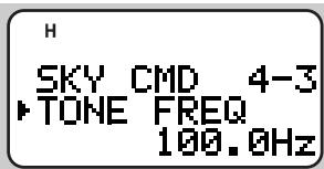
CONTROL OPERATION
When in the Sky Command mode, the keys of the Commander will function as below. Only the functions of [LAMP], [MONI], and the VOL control will not change. First switch ON the HF transceiver and press [SYNC] on the Commander.
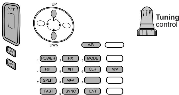
Each time you press the desired key, the Commander will automatically enter transmit mode and send the corresponding control command to the Transporter.
| To switch ON/ OFF the HF transceiver | Press [POWER]. |
| To transmit audio on a HF frequency | Press and hold the PTT switch, then speak into the microphone. |
| To receive audio on a HF frequency | Press [RX]. |
| To monitor the UHF band on the Commander | Press and hold [MONI]. |
| Key | Function |
| Tuning control | Frequency or memory channel number change |
| UP/ DWN | RIT offset or XIT offset change |
| A/B | In VFO mode: VFO A/ VFO B switch In Memory Recall mode: no change |
| POWER1 | Power ON/ OFF |
| RX1 | HF frequency receive ON/ OFF |
| MODE1 | Modulation mode switch |
| RIT1 | RIT ON/ OFF |
| XIT1 | XIT ON/ OFF |
| CLR1 | RIT offset or XIT offset clear |
| SPLIT1 | Split-frequency ON/ OFF |
| M\V1 | Transfer from Memory to VFO |
| FAST | In LSB, USB, or CW mode: 10 Hz/ 1 kHz switch In FM or AM mode: 1 kHz/ 10 kHz switch |
| SYNC1 | Current settings retrieve (from HF transceiver) |
| ENT | In VFO mode: frequency entry ON In Memory Recall mode: channel number entry ON |
| M/V | VFO/ Memory Recall mode switch |
1 After pressing [ENT], you can use these keys as numeric keys to enter a frequency or memory channel number.
When [SYNC] is pressed, the Commander shows the current settings of the HF transceiver as below:
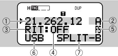
① HF frequency
② A (VFO A), B (VFO B), 00 ~ 99 (memory channel number)
③ RIT, XIT
④ OFF, -9.99 ~ +9.99
⑤ "FS" appears when [FAST] is ON.
⑥ LSB, USB, CW, FM, or AM
⑦ SPLIT-A: VFO A is used for transmitting.
SPLIT-B: VFO B is used for transmitting.
SPLIT-M: A memory channel is used for transmitting.
Note:
On the Transporter, only [LAMP], [MONI], and [MENU] will function. Pressing any other key will simply cause the Transporter to generate an error beep.
After pressing [MENU], you can access only Menu 4-4.
The Transporter will transmit its call sign in Morse every 10 minutes, using the 144 MHz band.
The APO timer does not operate on the transceiver with Transporter ON.
GENERAL INFORMATION
This product has been factory aligned and tested to specification before shipment. Attempting service or alignment without factory authorization can void the product warranty.
SERVICE
When returning this product to your dealer or service center for repair, pack it in its original box and packing material. Include a full description of the problem(s) experienced. Include your telephone number along with your name and address in case the service technician needs to call you; if available, include also your fax number and e-mail address. Don't return accessory items unless you feel they are directly related to the service problem.
You may return this product for service to the authorized KENWOOD dealer from whom you purchased it, or any authorized KENWOOD service center. Please do not send subassemblies or printed circuit boards. Send the complete product. A copy of the service report will be returned with the product.
SERVICE NOTE
If you desire to correspond on a technical or operational problem, please make your note legible, short, complete, and to the point. Help us help you by providing the following:
- Model and serial number of equipment
- Question or problem you are having
- Other equipment in your station pertaining to the problem
CAUTION
Do not pack the equipment in crushed newspapers for shipment! Extensive damage may result during rough handling or shipping.
Note:
Record the date of purchase, serial number and dealer from whom this product was purchased.
For your own information, retain a written record of any maintenance performed on this product.
When claiming warranty service, please include a photocopy of the bill of sale, or other proof-of-purchase showing the date of sale.
CLEANING
To clean the case of this product, use a neutral detergent (no strong chemicals) and a damp cloth.
TROUBLESHOOTING
The problems described in this table are commonly encountered operational malfunctions and are usually not caused by circuit failure.
| Problem | Probable Cause | Corrective Action | Ref. Page |
| Nothing appears on the display when the transceiver is switched ON, or the display is blinking ON and OFF. | 1 Low supply voltage 2 If using the optional DC cable: a) Bad power cable or connections b) Open (blown) power supply fuse | 1 Recharge the battery pack or replace the batteries. 2 a) Check the power cable and connections, then correct/replace as necessary. b) Investigate the cause for the open fuse. Replace the fuse. | 2, 4 5 — |
| Most keys and the Tuning control do not function. | 1 Transceiver Lock is ON (Key icon is visible). 2 The transceiver is in Channel Display mode. 3 Tone Alert is ON (Bell icon is visible). 4 Packet data was being transmitted using the data band. | 1 Press [F] (1 s) to switch OFF Transceiver Lock. 2 Press [A/B]+ POWER ON to exit Channel Display mode. 3 Press [F], [ENT] to switch OFF Tone Alert. 4 Operate the keys or the Tuning control after transmitting of packet data is completed. | 50 31 47 — |
| You cannot select the exact desired frequency using the [UP]/[DWN] or Tuning control. | The current frequency step size does not allow the frequency to be selected. | Select the appropriate frequency step size. | 46 |
| You cannot recall any memory channels. | You have stored no data in any of the memory channels using the current band. | Store the desired frequencies in memory channels using the current band. | 27 |
| You cannot transmit by pressing the PTT switch. | 1 You selected a frequency outside the allowable transmit frequency range. | 1 Select a frequency within the allowable transmit frequency range. | 7 |
| 2 You selected a transmit offset that places the transmit frequency outside the allowable range. | 2 Press [F], [MHz] repeatedly so neither “+” nor “-” is visible. | 21 | |
| 3 TX Inhibit is ON. | 3 Access Menu 1–5–5 and select “OFF”. | 51 | |
| 4 Tone Alert is ON. | 4 Press [F], [ENT] to switch OFF Tone Alert. | 47 | |
| 5 Packet data was being transmitted using the data band. | 5 Press the PTT switch after transmitting of packet data is completed. | — | |
| The transceiver switches OFF for no apparent reason. | The Automatic Power Off (APO) function is ON. | Switch OFF the APO function. | 49 |
| Turning the VOL control does not allow you to hear audio. | The speaker for the band you wanted to monitor was muted. | Press [BAL], then [UP]/[DWN] to correctly adjust the volume balance between the two bands. | 48 |
| Packet operation results in no connects with other stations. | 1 The squelch is open. | 1 Select the correct squelch level so that the squelch is opened only when signals are present. | 8 |
| 2 You did not select the same transfer rate as the target station. | 2 Use HBAUD command to select the appropriate transfer rate. | 54 | |
| You cannot transmit any APRS data. | 1 Beacon is OFF. 2 The squelch is open. 3 The data band is inactive. 4 The built-in TNC is OFF. 5 You selected Packet mode. | Press [BCON] to switch Beacon ON. Select the correct squelch level so that the squelch is opened only when signals are present. If you have blanked the data band, press [A/B] or [DUAL] to active it. Press [TNC] to switch ON the TNC. Press [TNC] twice so that only "→" appears. | 74 8 48 62 62 |
| When using a GPS receiver, you cannot correctly transmit position data. | The GPS receiver did not yet start correct measurement. | Before starting correct measurement, the GPS receiver generates a low-pitch tone every 10 seconds. When starting correct measurement, it generates a high-pitch tone. (If not using a GPS receiver, access Menu 2-2 and select "NOT USED"). | - |
| You cannot receive any APRS data. | You did not correctly program a group code. | Access Menu 2-A and program "APK001". | 71 |
| The Commander fails to display the status of the HF transceiver. | 1 You did not correctly program call signs on the Commander and Transporter. 2 You did not select the correct communication parameters on the HF transceiver. | On both the Commander and Transporter, access Menu 4-1 and 4-2 to program the correct call signs. On the HF transceiver, select 9600 bps and 1 stop bit using the Menu Setup function. | 86 85 |
| You cannot transmit audio from the HF transceiver. | You did not select the same tone frequency on the Commander and Transporter. | On both the Commander and Transporter, access Menu 4-3 to select the same tone frequency. | 85 |
| Problem | Probable Cause | Corrective Action | Ref. Page |
| Operating the Commander simply causes it to output an error beep and does not allow you to control the HF transceiver. | 1 Too large distance between the Commander and Transporter prevents correct data communications. 2 Bad radio wave conditions prevent control commands from being correctly transmitted. | 1 Operate the Commander within a distance that allows the two transceivers to show a full-scale S-meter reading. 2 Press [SYNC] occasionally to read the status of the HF transceiver. | — 87 |
| You cannot hear audio received by the HF transceiver. | You switched ON the CTCSS on the 144 MHz band of the Commander. | Press [F], [3] to switch OFF the CTCSS. | 40 |
| You cannot superimpose information onto the VC-H1 monitor. | You failed to correctly enter information to be superimposed. | Use Menu 3-1 to 3-6 to correctly enter the desired information. | 58, 59 |
| You cannot program the VC-H1 with a SSTV mode. | Bad cable connections. | Refer to the instruction manual for the VC-H1 and correctly connect the VC-H1 to the transceiver. | 57 |
Note: When two received frequencies have relationships per the equation below or other similar relationships, an internal heterodyne may be heard. This is not a defect.
2 (f_U - 45.05) - 4(f_V + 38.85) = 38.85 or 45.05
(f_U - 45.05) - 2(f_V + 38.85) = 38.85
n(f_SV - 45.05) - n(f_V + 38.85) = 38.85 or 45.05 where n = 3, 4, or 5 .
fV = VHF frequency (band A )
fU = UHF frequency (band B )
f_SV = VHF frequency (band B )
OPTIONAL ACCESSORIES
SMC-32
Speaker Microphone
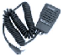
SMC-33
Remote Control Speaker Microphone

SMC-34
Remote Control Speaker Microphone (with Volume Control)
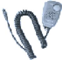
HMC-3
Head Set with VOX/PTT

EMC-3
Clip Microphone with Earphone

PB-38
Standard Battery Pack (6 V/ 650 mAh)
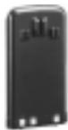
PB-39
High-power Battery Pack (9.6 V/ 600 mAh)
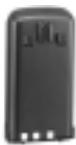
BT-11
Battery Case
BC-17
Wall Charger
BC-19
Rapid Charger
SC-40
Soft Case
PG-2W
DC Cable
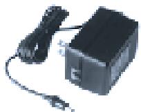


PG-3J
Filtered Cigarette Lighter Cable
VC-H1
Interactive Visual Communicator
PG-4V
Connection Cable to VC-H1

PG-4R
Sky Command Cable Kit (U.S.A./ Canada only)

PG-4W
Connection Cable to Computer (With a memory store program 1 and a separate manual (document file) 2)

This software is mainly used to program memory channels via a personal computer.
2 This manual gives further detailed information on specialized communications including Packet and APRS.
CONNECTING EQUIPMENT FOR REMOTE CONTROL
Make connections as shown when remotely controlling equipment.
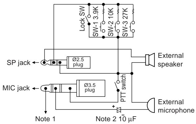
Note 1: Voltage is developed across the 100 resistor in the 3.5V line in the transceiver. When 2mA flows, approximately 3.3V is developed.
Note 2: A 10 F capacitor is not required in the following cases:
- When the other equipment has DC blocking capacitors.
- When a 2-terminal electret condenser microphone is used.
CONNECTING OTHER EXTERNAL EQUIPMENT
When connecting an external speaker, an external microphone, or other equipment such as a TNC for packet radio to the SP jack or MIC jack, refer to the diagram below.
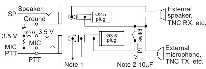
Note 1: Voltage is developed across the 100 resistor in the 3.5V line in the transceiver. When 2mA flows, approximately 3.3V is developed.
Note 2: A 10 F capacitor is not required in the following cases:
- When the other equipment has DC blocking capacitors.
- When a 2-terminal electret condenser microphone is used.
SPECIFICATIONS
| General | VHF Band | UHF Band | |
| Frequency range | TH-D7A | 144 ~ 148 MHz | 438 ~ 450 MHz |
| TH-D7E | 144 ~ 146 MHz | 430 ~ 440 MHz | |
| Mode | F3E (FM), F1D (GMSK), F2D (FSK) | ||
| Usable temperature range | -20°C ~ +60°C (-4°F ~ +140°F) | ||
| Rated voltage | External power supply (DC IN) | 5.5 ~ 16.0 V (13.8 V) | |
| Battery terminals | 4.5 ~ 15.0 V (6.0 V) | ||
| Current | Receive with no signals1 | Approx. 90 mA | |
| Battery Saver ON2 | Average 25 mA | ||
| TNC ON | Approx. 115 mA | ||
| Transmit with H, 13.8 V (DC IN) | Approx. 1.6 A | Approx. 1.7 A | |
| Transmit with H, 9.6 V (battery terminals) | Approx. 1.6 A | Approx. 1.7 A | |
| Transmit with H, 6.0 V (battery terminals) | Approx. 1.3 A | Approx. 1.4 A | |
| Transmit with L, 6.0 V (battery terminals) | Approx. 500 mA | ||
| Transmit with EL, 6.0 V (battery terminals) | Approx. 300 mA | ||
| Ground method | Negative | ||
| Dimensions(W x H x D)3 | TH-D7A (with a PB-39 installed) | 54.0 x 119.5 x 43.5 mm/ 2.13" x 4.70" x 1.71" | |
| TH-D7E (with a PB-38 installed) | 54.0 x 119.5 x 35.5 mm | ||
| Weight4 | TH-D7A (with a PB-39 installed) | Approx. 380 g/ 13.4 oz | |
| TH-D7E (with a PB-38 installed) | Approx. 340 g/ 12.0 oz | ||
| Frequency stability | -10 ~ +50 °C | Within ±10 ppm | |
| -20 ~ +60 °C | Within ±15 ppm | ||
| Microphone impedance | 2 kΩ | ||
| Antenna impedance | 50 Ω | ||
1 With one band blanked (TNC OFF): Approx. 45 mA
2 With one band blanked (TNC OFF): Approx. 25 mA
3 Projections not included
4 Antenna, belt hook, and hand strap included
| Transmitter | VHF Band | UHF Band | |
| Power output | H, 13.8 V | 6 W | 5.5 W |
| H, 9.6 V | Approx. 5 W | ||
| H, 6.0 V | Approx. 2.5 W | Approx. 2.2 W | |
| L, 6.0 V | Approx. 0.5 W | ||
| EL, 6.0 V | Approx. 50 mW | ||
| Modulation | Reactance | ||
| Maximum frequency deviation | Within ±5 kHz | ||
| Spurious emissions (at high transmit power) | -60 dB or less | ||
| Receiver | VHF Band | UHF Band | |
| Circuitry | Double conversion superheterodyne | ||
| 1st intermediate frequency | 38.85 MHz | 45.05 MHz | |
| 2nd intermediate frequency | 450 kHz | 455 kHz | |
| Sensitivity (12 dB SINAD) 1 | 0.18 μV or less | ||
| Squelch sensitivity | 0.1 μV or less | ||
| Selectivity (-6 dB) | 12 kHz or more | ||
| Selectivity (-40 dB) | 28 kHz or less | ||
| Audio output(10% distortion) | 9.6 V (battery terminals) | 450 mW or higher (8 Ω load) | |
| 6.0 V (battery terminals) | 300 mW or higher (8 Ω load) | ||
^1 VHF sub-band: 0.28 V or less
Specifications are subject to change without notice due to advancements in technology.
TNC COMMANDS LIST
The commands supported by the built-in TNC are listed below. You must enter a space between a command name (or short-form) and a parameter, or between two parameters; ex. AU OFF, BEACON EVERY 18.
| Command Name | Short | Default | Parameter | Description |
| AUTOLF | AU | ON | ON/OFF | When ON, sends a line feed (LF) to the computer after each carriage return (CR). |
| BEACON | B | EVERY 0 | EVERY/ AFTER n (n = 0 ~ 250) | If set to EVERY, sends a beacon packet at intervals of the specified period (n). If set to AFTER, sends a beacon packet only once after the specified period (n). The unit of n is 10 seconds. |
| BTEXT | BT | — | 0 ~ 159 characters | Specifies the content of the data portion of a beacon packet. |
| CALIBRAT | CAL | — | — | Sends a space/mark square wave (50/50 ratio). Enter Q to exit Calibrate mode and restore the Command mode. |
| CHECK | CH | 30 | 0 ~ 250 | Specifies the interval from signal drop-out until execution of disconnection. The unit of the parameter is 10 seconds. |
| CONNECT | C | — | Call1 (VIA call2, call3, ... call9) | Sends a connect request. Call1 is the call sign of the station to be connected to. Call2 to call9 are call signs of stations to be digipeated through. |
| CONVERSE | CONV or K | — | — | Causes the TNC to enter Converse mode. Press [Ctrl]+[C] to restore the Command mode. |
| CPACTIME | CP | OFF | ON/OFF | When ON and in Converse mode, sends a packet at intervals of the period determined by PACTIME. |
| CR | CR | ON | ON/OFF | When ON, appends a carriage return (CR) to all packets to be sent. |
| DISCONNE | D | — | — | Sends a disconnect request. |
| DISPLAY | DISP | — | — | Causes the TNC to display the current status of all the commands. You can also specify a class identifier A, C, H, I, L, M, or T to display the status of only the desired command class. Enter a space between the command name and a class identifier; ex. DISPLAY H.A (ASYNC): RS-232C port parametersC (CHAR): Special TNC charactersH (HEALTH): Counter parametersI (ID): ID parametersL (LINK): TNC-to-TNC link statusM (MONITOR): Monitor parametersT (TIMING): Timing parameters |
| DWAIT | DW | 30 | 0 ~ 250 | Specifies the interval from no carrier detection until execution of transmission. The unit of the parameter is 10 milliseconds. |
| ECHO | E | ON | ON/ OFF | When ON, causes the TNC to echo received characters to the computer. |
| FIRMRNR | FIR | OFF | ON/ OFF | The other station sends a notice (packet) to you if it is not ready to receive data. When ON, receiving such a notice causes the TNC to suspend transmission until it receives a “ready” notice. |
| FLOW | F | ON | ON/ OFF | When ON, starting key entry causes the computer to stop displaying received packets. |
| FRACK | FR | 3 | 0 ~ 250 | Specifies the interval from one transmission until retry of transmission. The unit of the parameter is 1 second. |
| GBAUD | GB | 4800 | 4800/ 9600 | Selects 4800 or 9600 bps as the transfer rate between the TNC and the GPS receiver. |
| GPSSEND | GPSS | — | 0 ~ 159 characters | Specifies the content of data to be output to the GPS receiver; this data is used to program the default settings on the receiver. The output data is not stored in memory. |
| GPTEXT | GPST | PNTS | 0 ~ 6 characters | Specifies the type of a message to be determined by LTEXT. |
| HBAUD | HB | 1200 | 1200/ 9600 | Selects 1200 or 9600 bps as the transfer rate between packet stations. |
| LOCATION | LOC | EVERY 0 | EVERY/ AFTER n (n = 0 ~ 250) | If set to EVERY, sends GPS data at intervals of the specified period (n). If set to AFTER, sends GPS data only once after the specified period (n). The unit of n is 10 seconds. |
| LPATH | LPA | GPS | Call1 (VIA call2, call3, ... call9) | Specifies call signs to send GPS data. Call1 is the call sign of the destination. Call2 to call9 are call signs of stations to be digipeated through. |
| LTEXT | LT | — | 0 ~ 159 characters | Specifies the content of a message to be included in GPS data. |
| LTMON | LTM | 0 | 0 ~ 250 | Specifies the interval for displaying a message determined by LTEXT on the screen; a message appears like a received beacon packet. The unit of the parameter is 1 second. |
| MCOM | MCOM | OFF | ON/ OFF | When ON, causes the TNC to also monitor control packets. When OFF, causes it to monitor only information packets. |
| MCON | MC | OFF | ON/ OFF | When ON, causes the TNC to monitor other stations while in connection with the target station. |
| MONITOR | M | ON | ON/ OFF | When ON, causes the TNC to monitor packets. |
| MRPT | MR | ON | ON/ OFF | When ON, causes the TNC to display the entire digipeat list for monitored packets. |
| MYCALL | MY | NOCALL | 6 characters + SSID | Specifies your call sign. |
| PACLEN | P | 128 | 0 ~ 255 | Specifies the maximum length of the data portion of a packet. |
| PACTIME | PACT | AFTER 10 | EVERY/ AFTER n (n = 0 ~ 250) | If set to EVERY, sends a packet at intervals of the specified period (n). If set to AFTER, sends a packet only once after the specified period (n). The unit of n is 100 milliseconds. |
| PERSIST | PE | 128 | 0 ~ 255 | Specifies a parameter to calculate probability for the PERSIST/SLOTTIME method. |
| PPERSIST | PP | ON | ON/ OFF | Causes the TNC to use the PERSIST/SLOTTIME method when ON, or the DWAIT method when OFF. |
| RESET | RESET | — | — | Restores the default status for all the commands. |
| RESPTIME | RES | 5 | 0 ~ 250 | Specifies the acknowledgment packet transmission delay. The unit of the parameter is 100 milliseconds. |
| RESTART | RESTART | — | — | Causes the TNC to function as if it is switched OFF then ON. |
| RETRY | RE | 10 | 0 ~ 15 | Specifies the number of transmission retries. If packets are not correctly accepted while in connection, a connect request is sent again after the specified number of retries. |
| SENDPAC | SE | 0D | 0 ~ $7F | Specifies a character which forces a packet to be sent. |
| SLOTTIME | SL | 3 | 0 ~ 250 | Specifies the period of random number generation intervals for the PERSIST/SLOTTIME method. The unit of the parameter is 10 milliseconds. |
| TRACE | TRAC | OFF | ON/ OFF | When ON, causes the TNC to display all received packets in their entirety. |
| TRIES | TRI | 0 | 0 ~ 15 | Specifies the number of transmission retries programmed in the retry counter. |
| TXDELAY | TX | 50 | 0 ~ 120 | Specifies the time delay between PTT ON and start of transmission. The unit of the parameter is 10 milliseconds. |
| UNPROTO | U | CQ | Call1 (VIA call2, call3, ... call9) | Specifies call signs to send a packet in Unprotocol mode. Call1 is the call sign of the destination. Call2 to call9 are call signs of stations to be digipeated through. |
| XFLOW | X | ON | ON/ OFF | Causes the TNC to perform software flow control when ON, or hardware flow control when OFF. |
QUICK REFERENCE GUIDE
Note: Not all functions are covered by this guide.
| Function | Key Operation | Ref. Page |
| AIP ON/ OFF (TH-D7A) | [MENU], [1], [5], [6] → [UP]/ [DWN] → [OK] | 51 |
| AIP ON/ OFF (TH-D7E) | [MENU], [1], [5], [8] → [UP]/ [DWN] → [OK] | 51 |
| APO ON/ OFF | [MENU], [1], [2], [2] → [UP]/ [DWN] → [OK] | 49 |
| Automatic Repeater Offset ON/ OFF | [MENU], [1], [5], [1] → [UP]/ [DWN] → [OK] | 23 |
| ASC ON | [REV] (1 s) | 24 |
| Battery Saver Interval Select | [MENU], [1], [2], [1] → [UP]/ [DWN] → [OK] | 49 |
| Beep ON/ OFF | [MENU], [1], [5], [3] → [UP]/ [DWN] → [OK] | 47 |
| Channel Display ON/ OFF | POWER OFF → [A/B] + POWER ON | 31 |
| Data Band Select | [MENU], [1], [4], [1] → [UP]/ [DWN] → [OK] | 55 |
| Display Contrast Adjust | [MENU], [1], [1], [2] → [UP]/ [DWN] → [OK] | 48 |
| Lamp Latch ON/ OFF | [F], [LAMP] | 48 |
| Power-ON Message Enter | [MENU], [1], [1], [1] → [UP]/ [DWN] → [OK] → Enter up to 8 digits | 50 |
| Function | Key Operation | Ref. Page |
| Reset (Partial/ Full) | POWER OFF → [F]+ POWER ON → [UP]/[DWN]→[OK]→ [UP]/[DWN]→[OK] | 32 |
| Scan Start | ||
| Call/Memory (TH-D7A only) | Recall a memory channel → [CALL] (1 s) | 38 |
| Call/VFO (TH-D7A only) | Select band → [VFO] → [CALL] (1 s) | 38 |
| Memory | Select band → [MR] (1 s) | 35 |
| MHz | Select band → [VFO] → [MHz] (1 s) | 36 |
| VFO | Select band → [VFO] (1 s) | 35 |
| Scan Resume Method Select | [MENU], [1], [5], [2] → [UP]/[DWN]→[OK] | 34 |
| Squelch Level Adjust | [F], [MONI] → [UP]/[DWN]→[OK] | 8 |
| Transceiver Lock | ||
| ON/ OFF | F (1 s) | 50 |
| Tuning Control Enable | [MENU], [1], [5], [4] → [UP]/[DWN]→[OK] | 50 |
| TX Deviation Switch (TH-D7E only) | [MENU], [1], [5], [7] → [UP]/[DWN]→[OK] | 51 |
| TX Inhibit ON/ OFF | [MENU], [1], [5], [5] → [UP]/[DWN]→[OK] | 51 |
First select the desired band.
| Key Operation | Function | Ref. Page |
| Recall a memory channel ⇒ [F], [0] | Memory Channel Lockout ON/ OFF | 36 |
| [F], [1] | Tone ON/ OFF | 22 |
| [F], [2] ⇒ [UP]/ [DWN] ⇒ [OK] | Tone Frequency Select | 22 |
| [F], [2] (1 s) | Tone Freq. ID Start | 25 |
| [F], [3] | CTCSS ON/ OFF | 40 |
| [F], [4] ⇒ [UP]/ [DWN] ⇒ [OK] | CTCSS Frequency Select | 39 |
| [F], [4] (1 s) | CTCSS Freq. ID Start | 40 |
| [F], [5] ⇒ [UP]/ [DWN] ⇒ [OK] | Offset Frequency Select | 21 |
| Select 118 MHz band ⇒ [F], [6] | AM/FM Mode Switch1 | 51 |
| [VFO] ⇒ [F], [7] ⇒ [UP]/ [DWN] ⇒ [OK] ⇒ [UP]/ [DWN] ⇒ [OK] | Lower/ Upper Freq. Limit Select | 46 |
| [F], [8] ⇒ [UP]/ [DWN] ⇒ [OK] | Frequency Step Size Select | 46 |
| Recall a memory channel ⇒ [F], [9] ⇒ [UP]/ [DWN] ⇒ [OK] ⇒ Enter up to 8 digits | Naming a Memory Channel | 29 |
TH-D7A only
Press [MENU] first to access the APRS Menu Nos.
| Key Operation | Selection | Ref. Page |
| [2], [1] → [UP]/ [DWN] → [OK] → Enter up to 9 digits | My Call Sign | 66 |
| [2], [2] → [UP]/ [DWN] → [OK] | GPS Receiver | 62 |
| [2], [3] → See reference page | Latitude/ Longitude Data | 68 |
| [2], [4] → [UP]/ [DWN] → [OK] | Position Comment | 69 |
| [2], [5] → [UP]/ [DWN] → [OK] | Station Icon | 67 |
| [2], [6] → [UP]/ [DWN] → [OK] → Enter up to 20 digits | Status Text | 70 |
| [2], [7] → [UP]/ [DWN] → [OK] | Beacon Transmit Interval | 75 |
| [2], [8] → [UP]/ [DWN] → [OK] → Enter up to 32 digits | Packet Path | 72 |
| [2], [9] → [UP]/ [DWN] → [OK] | Beacon Transmit Method | 74 |
| [2], [A] → [UP]/ [DWN] → [OK] → Enter up to 9 digits | Group Code | 71 |
| [2], [B] → [UP]/ [DWN] → [OK] | Reception Restriction Distance | 75 |
| [2], [C] → [UP]/ [DWN] → [OK] | Unit | 65 |
INDEX
Accessories
Optional 94
Supplied 1
Advanced Intercept Point (AIP) 51
APRS
Programming 66~75
Receiving 63
Transmitting 74
APRS Message
Entering 79
Receiving 77
Transmitting 80
Automatic Power Off (APO) 49
Automatic Simplex Check (ASC) 24
Band, Selecting 7, 12
Battery Saver 49
Beep ON/OFF 47
Call Channel
Contents, Changing 30
Recalling 30
Channel Display 31
CTCSS
Freq. ID 40
Frequency, Selecting 39
Using 40
Data Band 55
Display Contrast, Adjusting 48
DTMF
Making Calls 41
Storing Numbers 42
Transmitting Stored Numbers 43
TX Hold 41
Frequency, Selecting 7, 45
Frequency Step Size 46
Full Duplex 55
Lamp Function 48
Lock, Transceiver 50
Memory Channels
Clearing 28
Initializing 32
Locking Out 36
Naming 29
Recalling 28
Storing, Odd-split 27
Storing, Simplex 27
Transfer to VFO 31
Menu 16
Microphone Control 44
Offset
Automatic Repeater 23
Offset Direction 21
Offset Frequency 21
Packet Operation 52
Power-ON Message 50
Programmable VFO 46
Repeater Access 20
Reset
Full 32
Partial (VFO) 32
Reverse Function 24
Scan
Call/Memory 38
Call/VFO 38
Memory 35
MHz 36
Program 37
Resume Method 34
VFO 35
Sky Command II (TH-D7A only) ....83
Slow-Scan Television (SSTV) 57
Specifications 97
Squelch, Adjusting 8
TNC 53
Tone
Activating 22
Freq. ID 25
Frequency, Selecting 22
Tone Alert 47
Transmit Power, Selecting 9
Troubleshooting 90
TX Deviation (TH-D7E only) 51
TXInhibit. 51
Volume Balance, Adjusting 48
Wireless Remote Control
(TH-D7A only) 81
KENWOOD
- MODELS COVERED BY THIS MANUAL
- FEATURES
- ATTENTION (U.S.A. Only):
- FCC WARNING
- INFORMATION TO THE DIGITAL DEVICE USER REQUIRED BY THE FCC
- PRECAUTIONS
- CONTENTS
- CHAPTER 1 PREPARATION
- CHAPTER ② FIRST QSO
- CHAPTER ③ OPERATING BASICS
- CHAPTER 4 GETTING ACQUAINTED
- CHAPTER 5 MENU SET-UP
- CHAPTER ⑦ MEMORY CHANNELS
- CHAPTER 8 SCAN
- CHAPTER 9 CONTINUOUS TONE CODED SQUEELCH SYSTEM (CTCSS)
- CHAPTER 10 DUAL TONE MULTI-FREQUENCY (DTMF) FUNCTIONS
- CHAPTER 11 MICROPHONE CONTROL
- CHAPTER 12 AUXILIARY FUNCTIONS
- SLOW-SCAN TELEVISION (SSTV) WITH VC-H1
- CHAPTER
- APRS®MESSAGE
- WIRELESS REMOTE CONTROL (TH-D7A ONLY)
- EQUIPMENT CONNECTIONS
- SPECIFICATIONS
- APPENDIX
- QUICK REFERENCE GUIDE
- INDEX
- CONVENTIONS FOLLOWED IN THIS MANUAL
- 1
- INSTALLING THE NiCd BATTERY PACK
- CHARGING THE NiCd BATTERY PACK
- CAUTION
- Note:
- INSTALLING THE ANTENNA
- INSTALLING THE HAND STRAP/ BELT HOOK
- INSTALLING ALKALINE BATTERIES
- WARNING
- CONNECTING WITH A REGULATED POWER SUPPLY
- CONNECTING WITH A CIGARETTE LIGHTER SOCKET
- FIRST QSO
- SWITCHING POWER ON/OFF
- ADJUSTING VOLUME
- SELECTING A BAND
- SELECTING A FREQUENCY
- ADJUSTING SQUELCH
- Press [F], [MONI].
- TRANSMITTING
- Selecting Output Power
- INDICATORS
- CURSOR KEYS
- UP/ DWN keys
- OK key
- ESC key
- BAND A & B
- BASIC TRANSCEIVER MODES
- VFO mode
- Memory Recall mode
- Function Select mode
- Menu mode
- Full Duplex mode
- Packet mode
- KEYPAD DIRECT ENTRY
- MENU ACCESS
- Offset Programming Flow
- PROGRAMMING OFFSET
- Selecting Offset Direction
- Selecting Offset Frequency
- Activating Tone Function
- Selecting a Tone Frequency
- AUTOMATIC REPEATER OFFSET
- U.S.A. and Canada versions
- REVERSE FUNCTION
- AUTOMATIC SIMPLEX CHECK (ASC)
- Press [REV] (1 s) to switch the function ON.
- TONE FREQ. ID
- MEMORY CHANNELS
- 7
- SIMPLEX & REPEATER OR ODD-SPLIT MEMORY CHANNEL?
- STORING SIMPLEX FREQUENCIES OR STANDARD REPEATER FREQUENCIES
- STORING ODD-SPLIT REPEATER FREQUENCIES
- RECALLING A MEMORY CHANNEL
- CLEARING A MEMORY CHANNEL
- NAMING A MEMORY CHANNEL
- CALL CHANNEL (TH-D7A ONLY)
- Recalling the Call Channel
- Reprogramming the Call Channel
- MEMORY-TO-VFO TRANSFER
- CHANNEL DISPLAY
- PARTIAL OR FULL RESET?
- SELECTING SCAN RESUME METHOD
- Time-Operated mode
- - Carrier-Operated mode
- - Seek mode
- VFO SCAN
- MEMORY SCAN
- Locking Out a Memory Channel
- MHz SCAN
- PROGRAM SCAN
- Setting Scan Limits
- Press [OK].
- Press [OK].
- Using Program Scan
- CALL/VFO SCAN (TH-D7A ONLY)
- CALL/MEMORY SCAN (TH-D7A ONLY)
- CONTINUOUS TONE CODED SQUEELCH SYSTEM (CTCSS)
- SELECTING A CTCSS FREQUENCY
- USINGCTCSS
- CTCSS FREQ. ID
- DUAL TONE MULTI-FREQUENCY (DTMF) FUNCTIONS
- MANUAL DIALING
- TX Hold
- AUTOMATIC DIALER
- Storing a DTMF Number in Memory
- Transmitting a Stored DTMF Number
- Press [PTT]+[MENU].
- AUXILIARY FUNCTIONS
- DIRECT FREQUENCY ENTRY
- CHANGING FREQUENCY STEP SIZE
- PROGRAMMABLE VFO
- TONE ALERT
- BEEP ON/OFF
- ADJUSTING VOLUME BALANCE
- Press [BAL].
- Press [UP]/[DWN] to change the setting.
- Press [OK] to complete the setting.
- LAMP FUNCTION
- ADJUSTING DISPLAY CONTRAST
- BLANKING A BAND DISPLAY
- AUTOMATIC POWER OFF (APO)
- BATTERYSAVER
- POWER-ONMESSAGE
- TRANSCEIVER LOCK
- TX INHIBIT
- SWITCHING AM/FM MODE (TH-D7A ONLY)
- ADVANCED INTERCEPT POINT (AIP)
- SWITCHING TX DEVIATION (TH-D7E ONLY)
- CONNECTING WITH A PERSONAL COMPUTER
- OPERATING TNC
- Command mode
- - Converse mode
- PREPARATION FLOW
- SELECTING DATA BAND
- FULL DUPLEX
- ENTERING CALL SIGN/MESSAGE/ RSV
- SELECTING COLOR FOR CALL SIGN/MESSAGE/RSV
- EXECUTING SUPERIMPOSITION
- VC-H1 CONTROL
- AUTOMATIC PACKET/ POSITION REPORTING SYSTEM
- OPERATION FLOW
- RECEIVING APRS DATA
- ACCESSING RECEIVED APRS DATA
- Press [LIST].
- Press [UP]/[DWN] to select the desired station.
- Press [OK].
- Press [LIST] twice to restore the frequency display.
- PROGRAMMING A CALL SIGN
- SELECTING YOUR STATION ICON
- ENTERING LATITUDE/ LONGITUDE DATA
- SELECTING A POSITION COMMENT
- ENTERING STATUS TEXT
- PROGRAMMING A GROUP CODE
- All calls:
- Special:
- Alternate net:
- PROGRAMMING A PACKET PATH
- Method 1 (Specific path):
- Method 2 (Generic path):
- Method 3 (WIDEN-N path):
- Method 4 (SSID path):
- SELECTING BEACON TRANSMIT METHOD
- SELECTING BEACON TRANSMIT INTERVAL
- RESTRICTING RECEPTION OF APRS DATA
- RECEIVING AMESSAGE
- ACCESSING RECEIVED APRS MESSAGES
- 17
- ENTERING AMESSAGE
- TRANSMITTING AMESSAGE
- PREPARATION
- CONTROL OPERATION
- CONNECTING THE TRANSPORTER WITH THE HF TRANSCEIVER
- PROGRAMMING CALL SIGNS
- PROGRAMMING A TONE FREQUENCY
- GENERAL INFORMATION
- SERVICE
- SERVICE NOTE
- CLEANING
- TROUBLESHOOTING
- OPTIONAL ACCESSORIES
- SMC-32
- SMC-33
- SMC-34
- HMC-3
- EMC-3
- PB-38
- PB-39
- BT-11
- BC-17
- BC-19
- SC-40
- PG-2W
- PG-3J
- VC-H1
- PG-4V
- PG-4R
- PG-4W
- CONNECTING EQUIPMENT FOR REMOTE CONTROL
- CONNECTING OTHER EXTERNAL EQUIPMENT
- TNC COMMANDS LIST
- Accessories
- APRS
- APRS Message
- Call Channel
- CTCSS
- DTMF
- Offset
- Reset
- Scan
- Tone
- KENWOOD
Brand : KENWOOD
Model : TH-D7E
Category : Ham Radio