
WWK 222H - Chauffe-eau instantané et ballon d'eau chaude STIEBEL ELTRON - Free user manual and instructions
Find the device manual for free WWK 222H STIEBEL ELTRON in PDF.

| Product Type | Heat pump water heater (indoor installation) |
| Brand | Stiebel Eltron |
| Model | WWK 222H |
| Category | Instantaneous water heater and hot water tank |
| Dimensions (Height x Diameter) | 1501 mm x 690 mm |
| Weight (empty) | 120 kg |
| Power Supply | 230 V, 1/N/PE 220-240 V, 50/60 Hz |
| Fuse Protection | C16 |
| Heating Output (Heat Pump, A15/W10-55) | 1.6 kW average |
| Electric Emergency/Booster Heater Power | 1.5 kW |
| Max. Operating Current | 9.7 A |
| DHW Set Temperature Range | 61 - 65 °C |
| DHW Energy Efficiency Class (load profile L) | A+ (indoor air) |
| Sound Power Level (EN 12102) | 60 dB(A) |
| Air Flow Rate | 550 m³/h |
| Refrigerant / Charge | R134a / 0.85 kg |
| Anode Type | Maintenance-free impressed current anode |
| Maintenance Intervals | Clean air intake grille every 6 months; check valves every 6 months; replace anode batteries every 3 years if power interruptions occur |
| Safety Features | T&P valve, pressure reducing valve, high limit safety cut-out, frost protection, boil-dry protection, motor overload relay |
| Permissible Ambient Temperature Range (Operation) | -5 °C to +42 °C (heat pump); -5 °C to +55 °C (cylinder) |
| Min. Installation Room Volume | 13 m³ (recirculation air mode) |
Frequently Asked Questions - WWK 222H STIEBEL ELTRON
User questions about WWK 222H STIEBEL ELTRON
0 question about this device. Answer the ones you know or ask your own.
Ask a new question about this device
Download the instructions for your Chauffe-eau instantané et ballon d'eau chaude in PDF format for free! Find your manual WWK 222H - STIEBEL ELTRON and take your electronic device back in hand. On this page are published all the documents necessary for the use of your device. WWK 222H by STIEBEL ELTRON.
USER MANUAL WWK 222H STIEBEL ELTRON
natural_image
Line drawing of a cylindrical industrial fan or vent with ventilation grilles (no text or symbols)STIEBEL ELTRON
SPECIAL INFORMATION
OPERATION
- General information ____ 4
1.1 Safety instructions 4
1.2 Other symbols in this documentation ____ 4
1.3 Units of measurement ____ 4
- Safety 4
2.1 Intended use 4
2.2 General safety instructions 5
2.3 Test symbols 6
- Appliance description 6
3.1 Heat pump operating principle 6
3.2 DHW heating 6
3.3 Appliance operation outside the application limits ____ 7
3.4 Frost protection 7
3.5 Minimum runtime and minimum pause time ____ 7
3.6 Connection of an external signal transmitter ____ 8
- Settings 8
4.1 Emergency shutdown 8
4.2 Weatherproof cover 8
4.3 Display and operating controls 9
4.4 Adjusting the settings 10
4.5 "Rapid heat-up" button 13
- Cleaning, care and maintenance 14
5.1 Protective anode and battery change ____ 14
- Troubleshooting 14
INSTALLATION
- Safety 17
7.1 General safety instructions 17
7.2 Instructions, standards and regulations ____ 17
- Appliance description 17
8.1 Standard delivery 17
8.2 Required accessories 17
8.3 Additional accessories 17
8.4 Incorrect use 17
- Preparation 17
9.1 Transport 17
9.2 Storage 18
9.3 Installation site 18
9.4 Siting the appliance 19
- Installation 20
10.1 Water connection 20
10.2 Condensate drain 21
10.3 Electrical connection 22
10.4 Assembling the appliance 24
- Commissioning 25
11.1 Initial start-up 25
11.2 Recommissioning 25
-
Settings 26
-
Appliance shutdown 28
-
Troubleshooting 28
14.1 Fault codes 29
14.2 Resetting the safety pressure limiter ____ 30
14.3 WWK 222 H / WWK 302 H: Resetting the high limit safety cut-out ____ 30
14.4 Motor overload relay 30
- Maintenance 30
15.1 Removing the appliance cover 30
15.2 Removing the casing ring 31
15.3 Cleaning the evaporator 31
15.4 Draining the cylinder 31
15.5 Descaling the electric emergency/booster heater ____ 32
15.6 Valves 32
15.7 Condensate drain 32
15.8 Replacing the power cable 32
15.9 Fitting the casing ring 32
15.10 Protective anode and battery change 32
15.11 Fitting the appliance cover 33
- Specification 34
16.1 Dimensions and connections 34
16.2 Wiring diagram 36
16.3 Fault conditions 37
16.4 Data table 38
16.5 Standardised output data 39
GUARANTEE
ENVIRONMENT AND RECYCLING
SpECIAL INFO mATION
- The appliance may be used by children over 8 years of age and persons with reduced physical, sensory or mental capabilities or a lack of experience and expertise, provided that they are supervised or they have been instructed on how to use the appliance safely and have understood the potential risks. Children must never play with the appliance. Cleaning and user maintenance must not be carried out by children without supervision.
- Observe all applicable national and regional regulations and instructions.
- Observe the minimum clearances (see chapter "Installation / Preparations / Siting the appliance").
- Observe the requirements concerning the installation room (see "Specification / Data table").
- The appliance is supplied with a flexible power cable without plug. In the case of a permanent connection, the appliance must be able to be separated from the power supply by an isolator that disconnects all poles with at least 3 mm contact separation. Contactors, circuit breakers or fuses can be used for this. This type of isolator must be installed in the fixed electrical installation according to the regulations. For Australia: Ensure that the appliance can be separated from the power supply by a suitable isolator. Contactors, circuit breakers, fuses or general purpose power plugs can be used for this. This type of isolator must be installed according to the electrical installation regulations.
- Observe the safety measures to prevent contact with dangerously high contact voltage.
- Observe the fuse protection required for the appliance (see chapter "Specification / Data table").
- If the power cable is faulty, replace it with a new one. The power cable must only be replaced (for example if damaged) by a qualified contractor.
-
The appliance is pressurised. During the heat-up process, expansion water will drip from the safety valve.
-
Activate the valves at least every 6 months to prevent them from becoming blocked, e.g. by limescale deposits.
- Drain the appliance as described in chapter "Installation / Maintenance and cleaning / Draining the cylinder".
- A T&P valve or a cold water expansion control valve, or both, must be installed. Observe all applicable national and regional regulations and instructions.
- The maximum pressure in the cold water supply line must be at least 20 % below the lowest response pressure of all installed safety valves. Otherwise a pressure reducing valve is required. If this is the case, install a pressure reducing valve in the cold water supply line. The pressure reducing valve must be set to 540 kPa if a safety valve is installed; otherwise to 700 kPa.
- Fit the drain pipe of the safety valve with a constant fall in a room free from the risk of frost.
- Size the drain pipe so that water can drain off unimpeded when the safety valve is fully opened.
- The safety valve drain aperture must remain open to atmosphere.
OpE ATION
1. General information
The chapters "Special information" and "Operation" are intended for both users and qualified contractors. The chapter "Installation" is intended for qualified contractors.

Note
Read these instructions carefully before using the appliance and retain them for future reference. Pass on these instructions to a new user if required.
1.1 Safety instructions
1.1.1 Structure of safety instructions

KEYWORD Type of risk Here, possible consequences are listed that may result from failure to observe the safety instructions.
▶ Steps to prevent the risk are listed.
1.1.2 Symbols, type of risk
| Symbol | Type of risk |
| Injury | |
| Electrocution | |
| Burns(burns, scalding) |
1.1.3 Keywords
| KEYWO D Meaning | |
| DANGER Failure to observe this information will result in serious injury or death. | |
| WARNING | Failure to observe this information may result in serious injury or death. |
| CAUTION | Failure to observe this information may result in non-serious or minor injury. |
1.2 Other symbols in this documentation

Note
General information is identified by the adjacent symbol.
▶ Read these texts carefully.
Symbol Meaning
| Material losses(appliance damage, consequential losses and environmental pollution) | |
| Appliance disposal |
This symbol indicates that you have to do something. The action you need to take is described step by step.
☐☐■ These symbols show you the software menu level (in this example level 3).
1.3 Units of measurement

Note
All measurements are given in mm unless stated otherwise.
2. Safety
2.1 Intended use
The purpose of this appliance is to heat domestic hot water within the application limits stated in the chapter "Specification / Data table".
The appliance is intended for domestic use. It can be used safely by untrained persons. The appliance can also be used in non-domestic environments, e.g. in small businesses, as long as it is used in the same way.
Any other use beyond that described shall be deemed inappropriate. Observation of these instructions and of the instructions for any accessories used is also part of the correct use of this appliance.
2.2 General safety instructions
The appliance should only be operated once it is fully installed and all safety equipment has been fitted.

WARNING Injury
The appliance may be used by children over 8 years of age and persons with reduced physical, sensory or mental capabilities or a lack of experience and expertise, provided that they are supervised or they have been instructed on how to use the appliance safely and have understood the potential risks. Children must never play with the appliance. Cleaning and user maintenance must not be carried out by children without supervision.

WARNING Electrocution
Contact with live components presents a threat to life. Damage to the cable insulation or to individual components may result in a risk to life.
▶ If there is damage to the insulation, switch off the power supply and arrange a repair. All work on the electrical installation must be carried out by a qualified contractor.

WARNING Burns
The water in the DHW cylinder can be heated to temperatures in excess of 60 °C. There is a risk of scalding at outlet temperatures in excess of 43 °C. Caution must be exercised when coming into contact with the outflowing water.

WARNING Burns
Touching hot components can lead to burns.
- When working on hot components, always wear protective working clothing and safety gloves. The pipework connected to the DHW outlet of the appliance can reach temperatures in excess of 60 °C.

WARNING Burns
The appliance is filled with refrigerant at the factory. In the event of refrigerant escaping due to a leak, avoid coming into contact with the refrigerant or inhaling the released vapours. Ventilate the rooms affected.

WARNING Electrocution
Never operate the appliance when the casing is open or without a cover.

CAUTION Injury
If objects are left on the appliance, noise emissions may increase due to resulting vibrations, and the objects could fall and cause injury.
▶ Never place any objects on top of the appliance.

Material losses
At the factory, the appliance is fitted with rechargeable batteries that ensure the power supply to the impressed current anode in the case of a power failure.
In order for the impressed current anode to protect the DHW cylinder in the appliance against corrosion, the appliance must not be disconnected from the power supply for more than 16 hours if the DHW cylinder is filled with water and the impressed current anode is not separately connected to a continuous power supply. If regular interruptions to the power supply are not anticipated, the batteries will not require any maintenance. Replace the batteries for the impressed current anode every three years in the following cases:
- The impressed current anode is not separately connected to a continuous power supply and a switching contact regularly interrupts the power supply to the appliance.
- The security of supply is inadequate.
Failure to observe this point puts the appliance at risk of damage.
Never use batteries that cannot be charged. Only rechargeable nickel metal hydride batteries (NiMH) are permissible.
Batteries may be damaged in the appliance. Without a power supply, the impressed current anode and the cylinder would not be protected against corrosion.

Material losses
Ensure that the appliance, water pipes and safety valves are free from the risk of frost. If you disconnect the appliance from the power supply, it is no longer protected against frost.

Material losses
Never cover the appliance. Covering the air intake or air discharge leads to a reduced air supply. If the air supply is restricted, the operational reliability of the appliance cannot be guaranteed.

Material losses
Only operate the appliance when the DHW cylinder has been filled. The appliance is equipped with boil-dry protection to prevent operation if the DHW cylinder is not completely full of water.

Material losses
Heating liquids other than potable water is not permitted.

Material losses
Keep the appliance installation site free from air contaminated with oil or salt (chloride) and corrosive or explosive substances. Avoid contaminating the installation site with dust, hairspray or substances containing chlorine or ammonia.

Material losses
Operating the appliance outside the application limits (see chapter "Specification / Data table") is not permitted. The appliance may be damaged if operated continuously outside the application limits.

Note
The appliance is pressurised. During the heat-up process, expansion water will drip from the safety valve.
▶ If water continues to drip when heating is completed, please inform your qualified contractor.
2.3 Test symbols
See type plate on the appliance.
3. Appliance description
This appliance enables DHW to be supplied efficiently to several draw-off points using renewable energy. The appliance extracts heat from the ambient air. This heat is used, along with additional electrical energy, to heat up the water in the DHW cylinder. The amount of electrical energy and time required to heat up the DHW depend on the temperature of the air drawn in and the temperature of the water in the cylinder. When the air intake temperature drops, the heating output of the heat pump is reduced and the heat-up time is extended.
In the case of indoor installation, the air inside the installation room can be cooled by 1 °C to 3 °C due to heat extraction. The appliance also extracts moisture from the air, which turns into condensate. The condensate is removed from the appliance via the condensate drain.
The appliance has an electronic control unit with LC display. The display shows parameters of interest, such as the top hot water temperature, mixed hot water volume, etc. It also indicates when the unit is idle, heating or engaged in defrosting, as well as the presence of errors and faults. Subject to the power supply and your draw-off patterns, the water is heated automatically to the selected set temperature.
External signal transmitters can be integrated via the built-in contact input, e.g. a photovoltaic system to make use of solar power generated on site.
When a DHW draw-off point is opened, the hot water is pushed out of the appliance by the inflow of cold water.
The heat pump drive unit is located in the upper section of the appliance. The DHW cylinder is located in the lower section of the appliance. To protect against corrosion, the DHW cylinder is coated internally with special enamel and is additionally equipped with an impressed current anode.
The appliance's nominal maximum available amount of DHW is designed for the recommended number of users with average user behaviour.
3.1 Heat pump operating principle
A closed circuit within the appliance contains refrigerant (see "Specification / Data table"). This refrigerant evaporates at low temperatures. In the evaporator, which extracts heat from the air drawn in, the refrigerant changes from a liquid into a gaseous state. A compressor draws in the gaseous refrigerant and compresses it. This increase in pressure raises the refrigerant temperature. This requires electrical energy.
The energy (motor heat) is not lost, but reaches the downstream condenser together with the compressed refrigerant. There, the refrigerant transfers heat to the DHW cylinder. An expansion valve then reduces the still prevalent pressure and the cyclical process starts again.
3.2 DHW heating
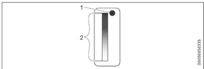
1 Cylinder top sensor
2 Integral sensor
The appliance is equipped with two temperature sensors.
- The cylinder top sensor captures the water temperature in the upper section of the cylinder.
- The integral sensor is a temperature sensor affixed over the entire cylinder height. The integral sensor determines the average cylinder temperature.
The appliance display indicates the temperature in the upper section of the cylinder, which is captured by the cylinder top sensor. The appliance control unit uses the average cylinder temperature captured by the integral sensor.
DHW heating is started when the available mixed water volume decreases to the percentage of the maximum mixed water volume set in the "Charge level" parameter.
The temperature captured by the cylinder top sensor may still correspond to the set temperature.
For information on the heat-up time, see chapter "Specification". The calculation of the available mixed water volume is based on the average cylinder temperature. The mixed water volume is only calculated if the water temperature in the upper section of the cylinder is higher than 40 °C.
DHW is normally heated by the heat pump of the appliance (see chapter "Specification / Data table").

Note
If the appliance has been isolated from the power supply during operation, the compressor will only restart after the pressure inside the refrigerant circuit has been equalised. Pressure equalisation can take several minutes.
WWK 222 H | WWK 302 H : Electric emergency/booster heater
When the temperature in the upper section of the DHW cylinder drops 12 K below the selected set temperature, the appliance automatically switches on the electric emergency/booster heater. When the temperature in the upper section of the DHW cylinder rises 2 K above the selected set temperature, the appliance switches off the electric emergency/booster heater.
In the event of an appliance fault, the electric emergency/booster heater can be activated in emergency heating mode, provided a flashing fault key is displayed. See chapter "Settings / 'Rapid heat-up' button / Emergency heating mode".
In the event of a higher hot water demand on a single occasion, use the "Rapid heat-up" button to activate the emergency/booster heater manually for one-off heat-up in addition to the heat pump. See chapter "Settings / 'Rapid heat-up' button / Rapid/comfort heat-up".
3.3 Appliance operation outside the application limits
▶ To guarantee fault-free operation of the appliance, make sure you operate the appliance within its application limits (see chapter "Specification / Data table").
3.3.1 Ambient temperatures below the application limit
Outside the application limits, the appliance blocks the compressor from operating. This could lead to reduced DHW convenience. If the appliance has an electric emergency/booster heater, the appliance enables this when there is a demand for water heating and the lower application limit has been undershot.
Low ambient temperatures may result in the formation of hoar frost on the evaporator depending on the air humidity and water temperature.
Active defrosting
The appliance is equipped with active hot gas defrosting, which allows quick defrosting of the evaporator when needed. During defrosting, the appliance fan is disabled. The compressor continues to run. A solenoid valve routes the hot gas directly to the evaporator. While this is happening, refrigerant flow to the condenser is disabled by another solenoid valve.
In contrast to conventional defrosting methods, the appliance guarantees that this defrosting takes place only when needed.

Note
Heat-up times are longer while the evaporator is defrosting.
3.3.2 Ambient temperatures above the application limit
Outside the application limits, the appliance blocks the compressor. This could lead to reduced DHW convenience. If the appliance has an electric emergency/booster heater, the appliance enables this when there is a demand for water heating and the upper application limit has been exceeded.
3.4 Frost protection
The appliance activates the frost protection function if the integral sensor in the DHW cylinder captures a temperature below 8 °C . The appliance then heats the water by means of the heat pump and the electric emergency/booster heater. The heat pump and electric emergency/booster heater switch off when the temperature captured by the integral sensor reaches 16 °C .
3.5 Minimum runtime and minimum pause time

Material losses
When operating with external switching devices that can interrupt the power supply to the appliance, such as time switches, energy management systems or home automation systems, the following conditions must be adhered to:
- The minimum ON time is 60 minutes.
- The minimum pause time following a shutdown is 20 minutes.
- The appliance should not be switched on/off more than 10 times per day.
- The breaking capacity of the switching actuator must meet the fuse protection requirements (see chapter "Specification / Data table").

Material losses
If you disconnect the appliance from the power supply, it is no longer protected against frost.

Material losses
At the factory, the appliance is fitted with rechargeable batteries that ensure the power supply to the impressed current anode in the case of a power failure.
In order for the impressed current anode to protect the DHW cylinder in the appliance against corrosion, the appliance must not be disconnected from the power supply for more than 16 hours if the DHW cylinder is filled with water and the impressed current anode is not separately connected to a continuous power supply.
If regular interruptions to the power supply are not anticipated, the batteries will not require any maintenance. Replace the batteries for the impressed current anode every three years in the following cases:
- The impressed current anode is not separately connected to a continuous power supply and a switching contact regularly interrupts the power supply to the appliance.
- The security of supply is inadequate.
Failure to observe this point puts the appliance at risk of damage.
Never use batteries that cannot be charged. Only rechargeable nickel metal hydride batteries (NiMH) are permissible.
Batteries may be damaged in the appliance. Without a power supply, the impressed current anode and the cylinder would not be protected against corrosion.
3.6 Connection of an external signal transmitter

Note
This type of connection must only be carried out by a qualified electrician.
External signal transmitters can be integrated via the built-in contact input, e.g. a PV system to take advantage of electricity generated on site.
The appliance has a second set temperature preselected at the factory. This is activated when there is an external switching signal. Set temperature 2 takes priority over the standard set temperature while there is an external switching signal. Following a one-off activation (signal is present for at least 1 minute), set temperature 2 applies for at least 20 minutes and takes priority over set temperature 1.
You can change set temperature 2 on the appliance (see chapter "Settings / Settings / Set temperature 2").
4. Settings

Material losses
Optimum operation is achieved with the factory default settings.
Any changes to these are strongly discouraged as they may affect output, service life and compliance with regulations.
4.1 Emergency shutdown
In the event of an emergency, carry out the following steps:
▶ Disconnect the appliance from the power supply at the fuse in the domestic distribution board or by unplugging the power plug.
▶ Shut off the cold water supply.
4.2 Weatherproof cover
The programming unit is equipped with a weatherproof cover to protect it from the elements.
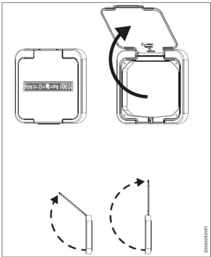
▶ Carefully flip up the lid of the weatherproof cover.
Two detents are provided so that you do not have to keep hold of the lid.
To close, carefully press the lid onto the appliance until the locking tabs at the sides lock in place.
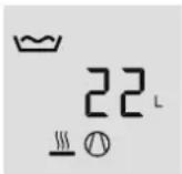
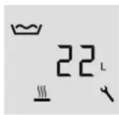
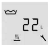
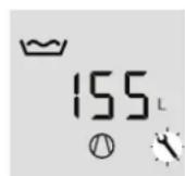
4.3 Display and operating controls

Note
15 seconds after every operation, the appliance automatically reverts to the default display (mixed water volume) and saves the set value.
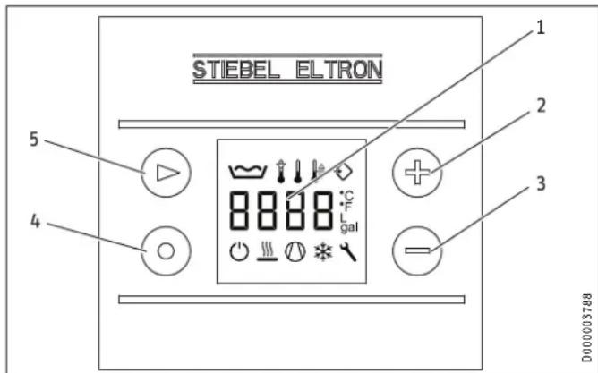
1 Mixed water volume display (litres|40 °C) / Display of actual temperature in upper cylinder section / Set temperature display 1 / Set temperature display 2 / Fault code display
2 "Plus" button
3 "Minus" button
4 "Rapid heat-up" button
5 "Menu" button
Symbols
Symbol
Description

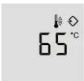
Mixed water volume: The currently available mixed water volume at 40 °C and at 15 °C cold water temperature is shown.

Set temperature adjustment: Subject to intake temperature and hot gas temperature, the appliance may temporarily reduce the set temperature to the actual value captured by the integral sensor. The appliance displays the "Set temperature adjustment" symbol and blocks DHW heating until the actual temperature captured by the integral sensor is 6 K below the temporary set temperature. DHW heating is then re-enabled and the originally selected set temperature is applied again.

Actual temperature: The current actual temperature is shown. The actual temperature indicates the temperature in the upper section of the DHW cylinder and therefore largely corresponds to the outlet temperature.

Set temperature

External signal transmitter: Set temperature 2 is the DHW temperature to which the appliance regulates if an external signal transmitter is connected and active.

Standby: The symbol flashes if the appliance PCB and load (compressor) are supplied with power separately. This connection option is required if the appliance is to be operated via switchable sockets in an energy management system, for example (see chapter "Electrical connection").

Electric emergency/booster heater: This symbol indicates the presence of a demand on this component. This symbol being displayed does not necessarily mean that the electric emergency/booster heater is running.

Heat pump: This symbol indicates the presence of a demand on this component. This symbol being displayed does not necessarily mean that the compressor is running.

Defrost active

Service/fault: Notify your qualified contractor if the "Service/fault" symbol appears on the display. Continuous illumination of the symbol indicates that the fault is not preventing appliance operation. A flashing "Service/fault" symbol indicates that water is not being heated and it is essential you notify your qualified contractor. Switching the appliance to emergency mode is a special case. The electric emergency/booster heater will then heat the water despite the flashing "Service/fault" symbol.
The "Electric emergency/booster heater" and "Heat pump" symbols are displayed when there is a demand for these appliance components. These symbols being displayed does not necessarily mean that the electric emergency/booster heater and the heat pump are running. Example: The appliance is in rapid/comfort heat-up mode. The electric emergency/booster heater switches off when the temperature in the upper cylinder section has reached 65 °C. The heat pump has not yet heated the lower section to 65 °C and the rapid/comfort heat-up function has therefore not been terminated yet. The electric emergency/booster heater symbol is displayed until the rapid/comfort heat-up function has terminated.
4.4 Adjusting the settings
The default display shows the mixed water volume.

The "Menu" button allows you to call up all information and adjustment options in sequence. The relevant symbol appears.
| ■ Menu | |
| ■ □ Mixed water volume display | |
| □■ Actual temperature display | |
| ■ □ Set temperature 1 | |
| ■ □ Set temperature 2 | |
| ■ □ Fan speed | |
| ■ □ Air intake temperature display | |
| ■ □ Enable the “Runtime-dependent rapid heat-up” function | in appliances with no electric emergency/booster heater, this parameter has no function. |
| ■ □ Time set for the “Runtime-dependent rapid heat-up” function | in appliances with no electric emergency/booster heater, this parameter has no function. |
| □■ Change units | |
| □■ Charge level | |
| ■ □ Fault code | |
| ■ □ E fault code | |
| ■ Advanced menu (with service plug only) | |
| ■ □ Integral sensor offset | |
| □■ Set the cylinder volume | |
| ■ □ Compressor lockout due to evaporator fault | |
| ■ □ Clear high pressure lockout | |
| ■ □ Clear low pressure lockout | |
| □■ Temperature of evaporator fins | |
| ■ □ Number of times hot gas temperature sensor was triggered | |
| □■ Number of defrost faults | |
| ■ □ Number of low pressure triggers | |
| ■ □ Number of high pressure triggers | |
| □■ Hot gas temperature switching value | |
| ■ □ Fan lead time | |
| □■ Integral sensor replacement | |
| □■ Set value limit | |
Menu
□ ■ Mixed water volume display
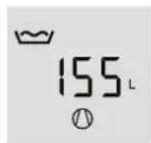

The currently available mixed water volume at 40 °C and at 15 °C cold water temperature is shown.
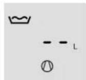
"-- L" is shown if less than 10 l mixed water is currently available.
| DHW demand for | Mixed water volume at 40 °C |
| Bath | 120-150 l |
| Shower | 30-50 l |
| Washing hands 2-5 l |
The mixed water volume that can be achieved depends on the cylinder size and the set temperature selected.
□■ Actual temperature display
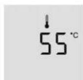

In the "Mixed water volume" menu, press "Menu" once to access the "Actual temperature" menu.
The "Actual temperature" symbol appears.
The current actual temperature is shown. The actual temperature is the temperature in the upper section of the DHW cylinder, and therefore largely corresponds to the outlet temperature.
□ ■ Set temperature 1

Note
For hygiene and other reasons, only change this value if instructed by Stiebel Eltron representative..
Set temperature 1 is the DHW temperature to which the appliance regulates if no external signal transmitter is connected and active.
| Factory setting | ||
| Set temperature 1 | °C | 61 |
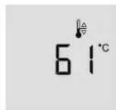

In the "Actual temperature" menu, press "Menu" once to access the "Set temperature 1" menu.

The set temperature 1 symbol appears. You can change the value using the "Plus" and "Minus" buttons. Setting range: 61 - 65 °C


Note
Another way to adjust set temperature 1 is to press the "Plus" or "Minus" buttons from within the default display (mixed water volume).
Frost protection

Only frost protection remains active if you set the set temperature to below 20 °C using the "Minus" button. The display shows "-- °C".


Set temperature 2

Note
For hygiene reasons, do not set a DHW temperature of less than 61 °C.
Set temperature 2 is the DHW temperature to which the appliance regulates if an external signal transmitter is connected and active.

In the "Set temperature 1" menu, press "Menu" once to access the "Set temperature 2" menu. The "External signal transmitter" symbol appears.
You can change the value using the "Plus" and "Minus" buttons. Setting range: 61 -65 °C

Operation with external signal transmitter

Material losses
See "Permissible voltage range for external signal transmitters" in chapter "Specification/data table".
As standard, these appliances are designed to allow you to allocate a separate, individual set DHW temperature to a connected external signal transmitter, such as a PV system or an economy tariff transmitter. This set temperature 2 is activated if the terminal connected to the external signal transmitter receives a signal (see chapter "Electrical connection / External signal transmitter connection option"). While activated, set temperature 2 replaces the standard set DHW temperature ("Set temperature 1").


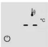
Air intake temperature display
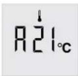

An "A" appears as the air intake temperature symbol.
The current air intake temperature is displayed.
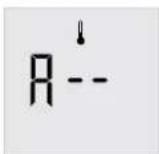
The air intake temperature is displayed only while the appliance fan is running. If it is not possible to establish an air intake temperature, two dashes are shown.


Enabling the "Runtime-dependent rapid heat-up" function

Note
In appliances with no electric emergency/booster heater, this parameter has no function.

Note
Only use the runtime-dependent quick heat-up if instructed by a Stiebel Eltron representative.
Enabling this function is likely to impact the efficiency of the product and may lead to unnecessary higher energy consumption and operational costs.
The appliance offers a runtime-dependent rapid heat-up option. If the selected set temperature is not reached by the heat pump after a user defined period, the appliance switches on the electric emergency/booster heater in parallel to back up the heat pump (subject to this function being enabled).
Once the set value has been reached, the electric emergency/booster heater remains inactive until the set time has elapsed again following a heat demand. This function is disabled at the factory.
This function is set in two stages. First enable the function and set the runtime in the second parameter.


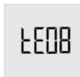
The tHE0 setting disables the runtime-dependent rapid heat-up function. This function is enabled via setting tHE1. The function is disabled at the factory.

h between the tHE0 and tHE1 settings using the "Plus" and "Minus" buttons. The tHE1 setting allows the electric emergency/booster heater to cut in if the set temperature is not reached after expiry of the runtime selected below.
■ □ Time set for the "Runtime-dependent rapid heat-up" function

Note
In appliances with no electric emergency/booster heater, this parameter has no function.
To avoid increased power consumption, only reduce the factory-set time for runtime-dependent rapid heat-up if necessary. See chapter "Specification / Appliance parameters".

Set the runtime using the "Plus" and

"Minus" buttons. After the set number of hours, the appliance checks whether the set temperature has been reached. If this is not the case, the appliance switches on the electric emergency/booster heater.
1 "Heat pump" symbol
2 "Electric emergency/booster heater" symbol
tHE0 Runtime-dependent rapid heat-up disabled
tHE1 Runtime-dependent rapid heat-up enabled
tE08 Adjustable number of hours (e.g. 8 in this case) during which heating is only provided by the heat pump
Change units
You can select whether the temperatures and the volume details are displayed in SI units or US units. If you select 1, the values are displayed in degrees Celsius and litres. If you select 0, the values are displayed in degrees Fahrenheit and gallons.

Press the "Menu" button until "SI" appears on the display.

g the "Plus" and "Minus" buttons, set whether the display should use SI units (1) or US units (0).

Charge level
Increasing this value increases the minimum available amount of DHW. The effect corresponds to a virtual shift of the temperature sensor downwards. This results in a faster recovery at the expense of higher energy consumption and reduced efficiency. Reducing this value has the opposite effect and results in a longer recovery at the expense of DHW availability.
DHW heating is started when the available mixed water volume decreases to the percentage of the maximum mixed water volume set in the "Charge level" parameter.
| Factory setting | |
| Charge level WWK 222 (H) % 56 | |
| Charge level WWK 302 (H) % 64 |
The displayed mixed water volume is based on a mixed water temperature of 40 °C. At water temperatures below 40 °C (±1 K), the mixed water volume is not calculated or displayed.
A further start condition, which overlaps with the charge level start conditions, is the reduction of the temperature captured by the cylinder top sensor to 6 K below the active set temperature.

Press the "Menu" button until an "L" followed by a number appears on the display.
You can change the value using the "Plus" and "Minus" buttons. Setting range: 30 - 100 %

Material losses
Do not change this parameter unless instructed by a Stiebel Eltron representative.
Fault code
If the "Service/fault" symbol is illuminated or flashes, you can call up the fault code using the "Menu" button. This menu remains disabled if no fault has arisen.
See chapter "Troubleshooting / Fault codes".
E fault code
A fault code preceded by E appears if the fault relates to the refrigerant circuit.
4.5 "Rapid heat-up" button

Note
In appliances with no electric emergency/booster heater, this button only allows you to clear the high pressure/low pressure lockout. You cannot start rapid/comfort heat-up or emergency heating mode.

Note
To start rapid/comfort heat-up with the "Rapid heat-up" button, the start screen must be displayed.

Press the "Rapid heat-up" button for two seconds.
The heat pump and electric emergency/booster heater symbols appear.
4.5.1 Rapid/comfort heat-up
Normally, the "Rapid heat-up" button is used to activate the rapid/comfort heat-up function, which enables you to cover an unexpectedly high DHW demand without changing any of the appliance's standard settings.
If rapid/comfort heat-up is activated manually by pressing the relevant button, the heat pump and the electric emergency/booster heater will start once in parallel, irrespective of the selected set temperature, and will remain active until the DHW temperature in the cylinder has reached 65 °C. To save energy, the electric emergency/booster heater switches off sooner, once a temperature of 65 °C has been achieved in the upper cylinder section (rapid heat-up).
The rapid/comfort heat-up function remains active until a temperature of 65 °C has been achieved in the entire DHW cylinder (comfort heat-up). The appliance then automatically switches back to the previously set parameters.

Note
The electric emergency/booster heater and heat pump symbols are displayed until the rapid/comfort heat-up function has terminated.

Note
To end rapid/comfort heat-up, press the "Rapid heat-up" button for two seconds.
4.5.2 Emergency mode
If the appliance is faulty, you can use emergency mode to activate the electric emergency/booster heater.
Following a DHW demand, the appliance measures the temperature rise every 15 minutes. If the temperature rise was <0.25^ within the 15 minute period, this is recorded by a counter. If the temperature rise did not reach >0.25^ in any 15 minute period over 13 hours, the compressor shuts down. The fault key flashes on the display and a fault code indicates that the appliance is not heating the water.

Press the "Rapid heat-up" button for two seconds.
The "Electrical emergency/booster heater" symbol appears. The "Service/fault" symbol flashes.
After the "Rapid heat-up" button has been pressed, the indicated fault code increments by a value of 256, as the fault codes are added together (see fault code table in chapter "Troubleshooting"). The fault key continues to flash. The electric emergency/booster heater is activated.
The current set temperature (set temperature 1 or set temperature 2) is ignored.
In emergency heating mode, the appliance operates with a fixed set temperature. In the upper cylinder section, the DHW is heated up to 65 °C by the electric emergency/booster heater.
Following one-off enabling of this function by means of the "Rapid heat-up" button, this function remains enabled for 7 days.
Following 7 days of emergency operation the electric emergency/booster heater is disabled. The fault code shown on the display decreases by 256.
If you press the "Rapid heat-up" button again for two seconds within the 7 days of emergency heating mode, the 7-day runtime for emergency heating mode will restart.
If the 7-day runtime for emergency heating mode has expired, you can restart emergency heating mode for a further 7 days by pressing "Rapid heat-up".
Pressing the "Rapid heat-up" button only enables emergency mode if a fault with fault code 8 occurred previously. In standard mode, pressing the "Rapid heat-up" button only triggers one-off heat-up of the DHW cylinder.
Emergency mode is no longer active after an interruption to the power supply. The appliance tries again to heat with the heat pump.
You can avoid having to wait until the temperature increase time has elapsed (see chapter "Specification") by starting manual emergency heating mode.
Manual emergency heating mode
If a fault has occurred and no fault code is displayed, you can activate emergency heating mode.

the "Plus" and "Minus" buttons pressed. In addition, press the "Menu" button and keep all three buttons pressed for 5 seconds.
The "Electrical emergency/booster heater" symbol appears. The "Service/fault" symbol flashes.
5. Cleaning, care and maintenance

WARNING Electrocution
- Only clean the exterior of the appliance.
- Never open the appliance.
- Do not insert objects through the grille into the interior of the appliance.
- Never spray the appliance with water.
- Never spray water into the appliance.

WARNING Injury
Maintenance work, such as checking electrical safety, must only be carried out by a qualified contractor.
| Appliance components | Care and maintenance tips |
| Casing Use a damp cloth to clean the casing sections. Never use abrasive or corrosive cleaning agents. | |
| Air intake grille / air discharge grille | Clean the air intake grille and air discharge grille every six months. Cobwebs or other dirt could obstruct the air supply to the appliance. |
| DHW cylinder | The DHW cylinder is equipped with a maintenance-free impressed current anode to protect it against corrosion. In order for the impressed current anode to protect the DHW cylinder in the appliance against corrosion, the appliance must not be disconnected from the power supply for more than 16 hours if the DHW cylinder is filled with water and the impressed current anode is not separately connected to a continuous power supply. |
| Electric emergency/booster heater | Have the electric emergency/booster heater descaled from time to time. This will extend the service life of the electric emergency/booster heater. |
| Safety equipment | Activate the valves at least every 6 months to prevent them from becoming blocked, e.g. by limescale deposits. |
| Evaporator Have the evaporator regularly checked by a qualified contractor. | |
| Condensate drain | Undo the condensate drain. Check that the condensate drain is clear and remove any dirt from the "Condensate drain" connection. |
5.1 Protective anode and battery change
The appliance is equipped with a maintenance-free impressed current anode that protects the cylinder from corrosion when it is connected to the power supply. At the factory, the appliance is fitted with rechargeable batteries that ensure the power supply to the impressed current anode in the case of a power failure. The appliance power supply must not be interrupted for more than 16 hours.
If the power supply is regularly interrupted by a switching contact or the security of supply is inadequate, the batteries of the impressed current anode must be replaced every three years. Failure to comply may result in damage to the appliance.
If regular interruptions to the power supply are not anticipated and there is security of supply, no maintenance of the batteries is required and the appliance is maintenance-free in this regard.
- Troubleshooting
| Problem | Cause | ►Remedy |
| No hot water is available. | No power at the appliance. Check that the appliance is connected to the power supply. | |
| A fuse in the distribution board has blown. | Check whether the fuses in your distribution board have blown. Contact a qualified contractor if the fuse blows again after the appliance is connected to the power supply. | |
| The air intake or air discharge of the appliance is blocked. | Check the air intake grille and air discharge grille for dirt. Remove any dirt (see chapter "Maintenance and care"). Ensure that the supply and extract air flow are unimpeded. | |
| Outside the application limits, the appliance blocks the compressor. This could lead to reduced DHW convenience. | No action required. The appliance will restart the compressor automatically within the application limits. | |
| The DHW cylinder is not completely filled. | The appliance restarts automatically when the DHW cylinder has been filled. | |
| After DHW was drawn off previously, the appliance was not able to fully heat up the cylinder content. | No action required. Let the appliance complete the heat-up process. | |
| The safety pressure limiter has responded 5 times in 5 hours. | Notify a qualified contractor. The appliance can only be unlocked with a service programming unit. | |
| The compressor is operational, but the fan is off. | If the appliance is in defrost mode, it may take up to an hour for the fan to switch on again. | No action required. However, if this continues for more than one hour, please consult a qualified contractor. |
| A safety valve is dripping. | The appliances are under water mains pressure. During the heat-up process, expansion water drips from a safety valve. | If water continues to drip when heating is completed, please inform your qualified contractor. |
| The condensate drain drips. | The surface temperature of the evaporator is lower than the dew point temperature of the ambient air. Condensate forms. | This is normal. No action required. The amount of condensate depends on the humidity level of the ambient air. |
| For indoor installation: The room temperature drops too low. | Operation of the appliance can cause the room temperature to fall by 1 to 3 °C. If the room temperature falls by more than 5 °C, check the room size (see chapter "Specification / Data table"). Increasing the room size by opening a door to another room will remedy this. | |
| The "Service/fault" symbol is continuously illuminated. | See chapter "Fault codes". | Notify a qualified contractor. A continuously illuminated "Service/fault" symbol indicates that a fault has occurred, but the heat pump is heating nevertheless. |
| The "Service/fault" symbol flashes and the water does not heat up. | See chapter "Fault codes". | It is imperative that you notify a qualified contractor quickly. A flashing "Service/fault" symbol indicates that a fault has occurred and the heat pump is no longer heating. |
| The "Defrost" symbol is shown. | The appliance is in defrost mode. | No action required. |
| The "Heat pump" symbol is flashing. | There is a heat demand, but the compressor is locked out. | No action required. The compressor restarts automatically after the compressor lockout time has elapsed. The symbol stops flashing automatically. |
| The “Electric emergency/booster heater” symbol is flashing. | A temperature controller has switched off the electric emergency/booster heater during rapid heat-up. | No action required. The appliance continues the rapid heat-up process using the heat pump. The symbol stops flashing when the controller re-enables the electric emergency/booster heater. The symbol goes out when the temperature throughout the DHW cylinder reaches the set rapid heat-up temperature. |
| The “Electric emergency/booster heater” symbol is illuminated but the electric emergency/booster heater is not operational. | The “Electric emergency/booster heater” symbol is illuminated when there is a demand. The internal controller of the electric emergency/booster heater may have ended electric heating. A possible cause may be a fault in the electric emergency/booster heater. A possible cause may be that the high limit safety cut-out has responded. | Have a qualified contractor check whether the controller of the electric emergency/booster heater is set correctly. The controller must be turned fully anti-clockwise. Have a qualified contractor check the high limit safety cut-out. |
Fault code
You can call up a fault code if the "Service/fault" symbol is flashing or continuously illuminated on the display.

Repeatedly press the "Menu" button until the fault code is shown after set temperature 2.
Fault code appears
| [SYZS] | Fault description Remedy | ||
| 2 | Continuously on | The cylinder top sensor is faulty. The actual temperature display switches from the cylinder top sensor to the integral sensor. The appliance continues to heat without any loss of comfort. The mixed water volume cannot be calculated and is displayed as "- -". | Notify a qualified contractor. |
| 4 | Continuously on | The integral sensor is faulty. In the event of a faulty integral sensor, the integral sensor is set to the value of the cylinder top sensor, and the mixed water volume is calculated using this value. The appliance continues to heat with a reduced start hysteresis.A mixed water volume is still calculated, based on the assumption that the cylinder top temperature is reached throughout the DHW cylinder. | Notify a qualified contractor. |
| 6 | Flashing | The cylinder top sensor and the integral sensor are faulty. The appliance no longer delivers heat. | Notify a qualified contractor. |
| Fault description Remedy | |||
| 8 | Flashing | The appliance has ascertained that the DHW cylinder has not been heated within the maximum temperature increase time, despite there being a demand. | You can temporarily continue to use the appliance by pressing the "Rapid heat-up" key to activate emergency heating mode. See chapter "Appliance description / Emergency mode". |
| 16 | Continuously on | A short circuit of the impressed current anode has occurred or the protective anode is faulty. | Immediately notify a qualified contractor, as the appliance is not protected against corrosion if the impressed current anode is faulty. |
| 32 | Flashing | The appliance is not being operated with a completely filled DHW cylinder. The appliance is not heating. | Fill the DHW cylinder of the appliance. The fault code disappears and the appliance starts. |
| The anode current is interrupted. The appliance is not heating. | Notify a qualified contractor. | ||
| 64 | Continuously on | The defrost temperature has not yet been reached after the maximum defrost time has lapsed. The compressor is faulty. | The fault is reset automatically once the evaporator temperature has risen to the defrost end temperature. |
| Notify a qualified con- | tractor. | ||
| 128 | Continuously on | There is no communication between the controller and the programming unit. The most recently selected set values are active. The appliance continues to heat. | Notify a qualified contractor. |
| 256 | Flashing | Manually activated emergency mode (only electric emergency/booster heater active) | See chapter "Appliance description / Emergency mode". |
| 512 | Flashing | A fault has occurred in the refrigerant circuit. | Notify a qualified contractor. |
If several faults occur, the fault codes are added together.
Example: If both the cylinder top sensor and the integral sensor are faulty, the display shows fault code 6 (=2+4).
Application scenarios for emergency heating mode
If the appliance shows fault code 8, you can manually enable emergency heating mode. If a different fault occurred previously, but did not cause the appliance to shut down, the display may show a fault code that is the result of several faults added together.
Listed below are the fault codes which will allow you to enable emergency heating mode.
| Fault code displayed | |
| 8 | 8 |
| 10 | Fault code 8 + fault code 2 |
| 12 | 8+4 |
| 24 | 8+16 |
| 26 | 8+2+16 |
| 28 | 8+4+16 |
| 138 | 8+2+128 |
| 140 | 8+4+128 |
| 152 | 8+16+128 |
| 154 | 8+2+16+128 |
| 156 | 8+4+16+128 |
When the appliance is operating in emergency heating mode, the fault code shown is incremented by 256.
E fault code
| Fault description | Remedy | ||
| E 1 | Flashing | The temperature sensor on the air inlet is faulty. | Notify a qualified contractor. |
| E 2 | Flashing | The temperature sensor on the evaporator is faulty. | Notify a qualified contractor. |
| E 4 | Continuously on | The hot gas temperature sensor is faulty. The appliance continues to heat. To protect the appliance, the (possibly higher) set temperature is reduced to the set value for setback. | Notify a qualified contractor. |
| E 16 | Continuously on | The high pressure switch has responded. Compressor heating mode is temporarily blocked. Compressor heating mode will continue as soon as the pressure has normalised. | Wait until the pressure has normalised. |
| E 32 | Continuously on | An electrical fault has occurred. | Notify a qualified contractor. |
| E 64 | Flashing | Evaporator temperature < Minimum evaporator temperature | Notify a qualified contractor. |
| E 128 | Flashing | A permanent pressure switch fault has occurred. A pressure fault occurred multiple times within a defined pressure fault evaluation time. | Notify a qualified contractor. |
Notifying a qualified contractor
If you cannot remedy the fault, notify your qualified contractor. In Australia, contact us directly (1800153351). To facilitate and speed up your enquiry, please provide the serial number from the type plate (000000-0000-000000). The type plate can be found on the left, above the "DHW outlet" connection.
Sample type plate
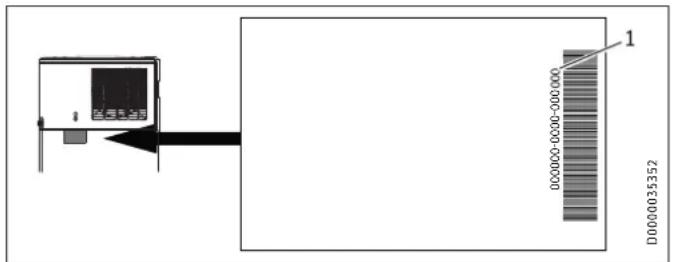
1 Number on the type plate
INSTALLATION
7. Safety
Only a qualified contractor should carry out installation, commissioning, maintenance and repair of the appliance.
7.1 General safety instructions
We guarantee trouble-free function and operational reliability only if original accessories and spare parts intended for the appliance are used.
7.2 Instructions, standards and regulations

Note
Observe all applicable national and regional regulations and instructions.

Note
The installation of this appliance shall conform to the Plumbing Code of Australia (PCA), and the New Zealand Building Code.
Take note of the appliance type plate and chapter "Specification".
8. Appliance description
8.1 Standard delivery

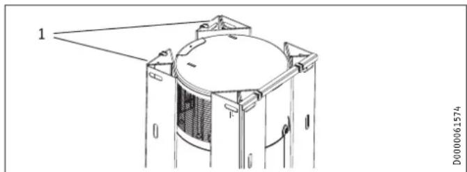
Note
The accessories are located in the corners of the packaging. Remove the accessories before disposing of the packaging.
natural_image
Technical line drawing of a mechanical component with labeled part 1 (no text or symbols beyond label)1 Corners of the packaging
The following are delivered with the appliance:
- Condensate drain bend
- 2 straight pipe adaptors from G 1 to G 3/4
- T&P valve G 1/2
- Reducer from R 3/4 male thread to G 1/2 female thread
8.2 Required accessories
Various safety assemblies are available that need to be selected subject to the static pressure. These type-tested safety assemblies protect the appliance against unacceptable excess pressure.
For Australia: Various safety assemblies are available to protect the appliance against unacceptable excess pressure and limit the DHW outlet temperature.
8.3 Additional accessories
- Condensate pump (if the condensate cannot be drained off with a naturally occurring fall)
8.4 Incorrect use
The following are not permitted:
- Operating the appliance when the casing is open
- Filling the appliance with a refrigerant other than the one detailed in chapter "Specification / Data table"
- Heating liquids other than potable water
Observe the list of requirements regarding the installation room and non-permissible installation sites (see chapter "Installation site").
9. Preparation
9.1 Transport

CAUTION Injury
▶ Observe the weight of the appliance.
▶ Use suitable transport aids (e.g. sack truck) and enough personnel for transportation.

Material losses
The appliance has a high centre of gravity and low overturning moment.
▶ Safeguard the appliance against falling over.
▶ Only set the appliance down on an even base.

Material losses
The appliance casing is not designed to withstand strong forces. Incorrect handling can lead to material losses of considerable extent.
▶ Observe the information on the packaging. Only remove the packaging shortly before installation.
Where possible, do not unpack the appliance until it has arrived in the installation room.
For transport and handling leave the appliance in its packaging and on the pallet. This enables brief horizontal transport and provides places to hold on to during transport.
If the appliance has to be unpacked before transportation, we recommend using a sack truck. Pad the contact surfaces to avoid damaging the appliance. Secure the appliance using a strap. Pad the areas between the strap and the appliance, and avoid over-tightening the strap. Where stairwells are narrow, you can carry the appliance by the handles on the sack truck or trolley and the foot of the appliance.
Vehicular transport

Material losses
The appliance must generally be stored and transported vertically.
On tarmac, asphalt, bitumen or otherwise paved roads you may transport the appliance horizontally over a maximum distance of 160 km. Strong shocks are not permissible.

Material losses
If transported horizontally, the appliance must always be laid on the shaded side of the box.
The appliance must not remain in a horizontal position for more than 24 hours.
If the appliance was transported horizontally, leave it to rest in a vertical position for at least one hour before commissioning.
▶ Observe the information on the packaging.
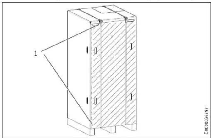
1 Recessed grips
Transport from vehicle to installation room
The cardboard box has reinforced handholds (recessed grips). You can use these recessed grips, as well as the pallet at the lower end, to carry the appliance into the installation room. Take note of the weight of the appliance and ensure sufficient personnel are available.
9.2 Storage
If it is necessary to store the appliance for a prolonged period before installation, observe the following information:
- Only store the appliance in a vertical position. Never store the appliance horizontally.
- Store the appliance in a location that is dry and largely dust-free.
- Protect the appliance from coming into contact with aggressive substances.
- Ensure the appliance is not subjected to shocks or vibrations.
9.3 Installation site

Material losses
Observe the following list of requirements regarding the installation site.
- Install the appliance where it will be exposed as little as possible to strong direct wind, extreme rain, sun or snow, but will still be well ventilated. Unhindered air intake and air discharge must be possible. If necessary, protect the appliance against the elements with a canopy, base and deflectors.
- The installation site must be free from flammable, highly combustible gases and substances, as well as high levels of dust.
- The application limits for the heat pump and DHW cylinder must be maintained (see chapter "Specification / Data table").
- The substrate of the installation site must be level and have sufficient load bearing capacity. Take note of the weight of the appliance with a full DHW cylinder (see chapter "Specification / Data table"). A floor with insufficient load bearing capacity is in danger of collapse. If the appliance is not level, there may be a risk of appliance damage.
- In the case of indoor installation, the size of the installation room must correspond to the application limits of the appliance (see chapter "Specification / Data table").
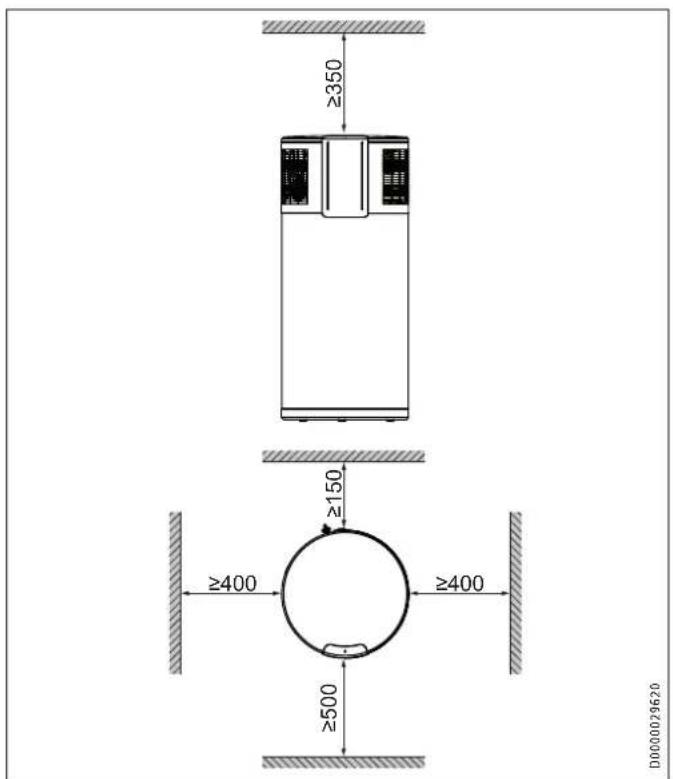
- Observe the safety clearances and protection zones.
- Always leave sufficient space to provide access for installation, maintenance and cleaning. Observe the minimum clearances (see "Preparations / Siting the appliance"). Otherwise, the energy efficiency may decrease and the service life may be reduced.
- Never install the appliance in locations with aggressive atmospheres. Never draw off supply air from locations with aggressive atmospheres. This may damage the appliance.
- Check for anything which may have adverse effects on the installation site or the air supply. This can decrease the energy efficiency and reduce the service life, for example.
- Never install the appliance in close proximity to outdoor air conditioning units. This can damage the fan, the compressor or the evaporator, for example.
- Ensure the operation of other equipment in the installation room is not impaired.
- To keep the water pipe lengths as short as possible, we recommend installing the appliance close to the kitchen or bathrooms.
- To prevent adverse effects from operating noise, do not install the appliance close to bedrooms.
| Examples of unacceptable installations | |
| Atmospheres containing ammonia | Sewage works, pigsties |
| Substances which block the evaporator | Air containing oil or fat, dust (cement, flour, etc.). Note: If the air contains hairspray (e.g. in hairdressing salons), the appliance should be operated with shorter maintenance intervals. |
| Saline environments Coastal installations (< 200 m from the coast) can reduce component service life. | |
| Atmospheres containing chlorine or chloride | Swimming pools, salt works |
| Atmospheres containing thermal water | |
| Formaldehyde in the atmosphere | Certain wood-based materials (e.g. OSB boards) |
| Certain insulating materials (e.g. foams based on urea-formaldehyde (UF in-situ foams)) | |
| Carboxylic acid in the atmosphere | Extract air from kitchens |
| Components of floor cleaners (e.g. vinegar cleaner) | |
Air polluted with these substances can cause corrosion of copper materials in the refrigerant circuit, especially the evaporator. This corrosion can lead to failure of the appliance. Any damage to the appliance caused in this way is not covered by the guarantee conditions.

Note
The appliance output data is calculated according to the relevant standards, using the intake temperature specified in the data table. Below this temperature the appliance efficiency and output decrease. The heat-up time is extended.

Note
You can improve the efficiency of the appliance by utilising the waste heat from other appliances to heat the DHW cylinder, e.g. boilers, tumble dryers or freezers.
If, for example, a tumble dryer releases dust at the installation site, the evaporator must be cleaned more frequently.
Sound emissions
The sound emissions are louder on the air intake and air discharge sides of the appliance than on the closed sides.
▶ Do not direct the air intake or air discharge towards noise-sensitive rooms of the house, e.g. bedrooms.

Note
For details on sounds emissions, see chapter "Specification / Data table".
9.4 Siting the appliance
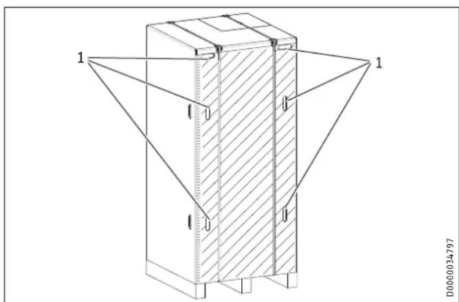
▶ Carefully undo the cardboard packaging at the clips.
1 Cardboard packaging clips
The appliance is secured to the pallet with metal brackets and screws. The metal brackets are hooked onto the feet underneath the floor plate of the appliance.

1 Metal bracket fixing screw
▶ Remove the fixing screws of the metal brackets from the pallet.
▶ Push the metal brackets a little towards the cylinder centre to unhook them from the appliance feet.
▶ Pull the metal brackets out from underneath the appliance.

Material losses
Take note of the appliance's weight and centre of gravity.
▶ Slightly tip the appliance and carefully roll the appliance off the pallet.
▶ Position the appliance in the final installation site.

Material losses
The appliance must be positioned vertically to avoid damage.
The appliance has height-adjustable feet below its base.
▶ Level the appliance horizontally using the height-adjustable feet.
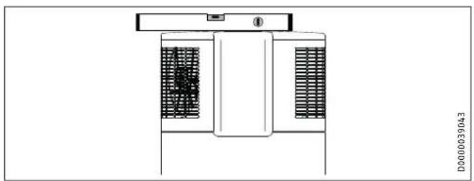
natural_image
Technical line drawing of a mechanical or electrical component with internal grating and mounting bracket (no text or symbols)9.4.1 Minimum clearances
▶ Maintain the minimum clearances.
10. Installation

WARNING Injury
Incorrect installation can lead to serious injury or material losses.
Before any work, ensure sufficient clearances for installation.
Handle sharp-edged components carefully.
10.1 Water connection

Material losses
Carry out all water connection and installation work in accordance with regulations.

Material losses
The corrosion protection provided by the anode can only be guaranteed when the electrical conductivity of the potable water is within the limits stated in chapter "Specification / Data table".
Cold water line
Galvanised steel, stainless steel, copper and plastic are approved materials.
A safety valve is required.
DHW line
Stainless steel, copper and plastic pipework are approved.

Material losses
When using plastic pipework, observe the manufacturer's data and chapter "Specification / Fault conditions".
Thoroughly flush the pipework before connecting the appliance. Foreign bodies, such as abraded plastic or metal, rust, sand or sealant can impair the operational reliability of the appliance.

Material losses
To protect the connections against corrosion, the water connection must be made with flat gaskets. The use of hemp on connections is not permissible.
DHW circulation
10.1.1 Safety equipment
A T&P valve or a cold water expansion control valve, or both, must be installed. Observe local and regional regulations.
T&P valve (850kPa)
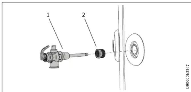
1 T&P valve
2 Reducer from R 3/4 male thread to Rp 1/2 female thread
▶ If specified, install a type-tested T&P valve with reducer at the "T&P valve" connection provided on the appliance.
The response pressure of the valve must be below or equal to the permissible operating pressure of the DHW cylinder. The valve protects the appliance against unacceptable excess pressure or temperature. The diameter of the cold water supply line must not be greater than the diameter of the valve.
▶ Ensure that the expansion water escaping from the valve can drip into a drain, e.g. a funnel or tundish.
Ensure the drain cannot be shut off.
▶ Size the drain pipe so that water can drain off unimpeded when the safety valve is fully opened.
▶ Ensure that the drain pipe of the safety valve is open to the outside.
▶ Fit the drain pipe of the safety valve with a constant downward slope and in a location free from the risk of frost.
Safety valve (cold water expansion control valve)
▶ If specified, install a type-tested 700 kPa safety valve (expansion control valve) in the cold water supply line.
The safety valve protects the appliance against unacceptable excess pressure. The diameter of the cold water supply line must not be greater than the diameter of the safety valve.
▶ Ensure that the expansion water escaping from the safety valve can drip into a drain, e.g. a tank or funnel.
Ensure the drain cannot be shut off.
▶ Size the drain pipe so that water can drain off unimpeded when the safety valve is fully opened.
▶ Ensure that the drain pipe of the safety valve is open to the outside.
▶ Fit the drain pipe of the safety valve with a constant fall in a room free from the risk of frost.
10.1.2 Pressure reducing valve
The maximum pressure in the cold water supply line must be at least 20 % below the lowest response pressure of all installed T&P valves. Otherwise a pressure reducing valve is required. If this is the case, install a pressure reducing valve in the cold water supply line. The pressure reducing valve must be set to 540 kPa if a safety valve is installed; otherwise to 700 kPa.
10.1.3 Drain valve
▶ Install a suitable drain valve at the lowest point in the cold water supply line.
10.1.4 Thermal insulation
▶ Insulate the DHW line and valves against heat loss and to improve energy efficiency in accordance with locally applicable regulations.
▶ Insulate the cold water supply line to prevent condensate forming.
10.1.5 DHW outlet

WARNING Burns
The water in the DHW cylinder can be heated to temperatures in excess of 60 °C . There is a risk of scalding at outlet temperatures in excess of 43 °C .
▶ Install a temperature limiter in all systems intended for personal hygiene, e.g. balancing valve, thermo-static mixing valve.
10.2 Condensate drain
Install a condensate drain hose in order to remove the condensate which forms.
- Connect the condensate drain bend included in the standard delivery to the "Condensate drain" connection.
▶ Connect a condensate drain hose to the condensate drain bend.
A siphon must be installed to prevent aggressive gases from the sewer entering the appliance. The condensate drain must be installed with an outlet that opens freely above the siphon.

Material losses
Ensure condensate cannot back up.
▶ Use a condensate drain hose with a diameter greater than the diameter of the condensate drain bend.
▶ Ensure the condensate drain hose is not kinked.
▶ Route the condensate drain hose with a continuous II.
The condensate drain must be open to atmosphere.
▶ Use a suitable condensate pump if there is insufficient fall. Take the building characteristics into account.
Condensate pan heater

Material losses
If the temperature at the installation site could continuously fall below freezing (1 - 2 days) you should install a condensate pan heater. The condensate pan heater is not part of the standard delivery.
When the compressor is running, install a load-dependent relay to switch on the condensate pan heater after a delay.
The condensate pan heater must have an external power supply.
10.3 Electrical connection

WARNING Electrocution
The appliance is supplied with a flexible power cable without plug. In the case of a permanent connection, the appliance must be able to be separated from the power supply by an isolator that disconnects all poles with at least 3 mm contact separation. Contactors, circuit breakers or fuses can be used for this. This type of isolator must be installed in the fixed electrical installation according to the regulations.
For Australia: Ensure that the appliance can be separated from the power supply by a suitable isolator. Contactors, circuit breakers, fuses or general purpose power plugs can be used for this. This type of isolator must be installed according to the electrical installation regulations.

WARNING Electrocution
Carry out all electrical connection and installation work in accordance with national and regional regulations.

WARNING Electrocution
Ensure that the appliance is connected to the earth conductor.

WARNING Electrocution
Observe the safety measures to prevent contact with dangerously high contact voltage.

WARNING Electrocution
Coming into contact with live components presents a threat to life. Disconnect the appliance from the power supply before carrying out work on its interior. Prevent the power supply from being switched on while you are working on the system.

WARNING Electrocution
Insufficient earthing can lead to electrocution. Ensure the appliance is earthed according to locally applicable requirements.

WARNING Electrocution
If the power cable is faulty, replace it with a new one. The power cable should only be replaced by a qualified contractor.

Material losses
Install a residual current device (RCD).

Material losses
The specified voltage must match the mains voltage. Observe the type plate.

Material losses
Observe the fuse protection required for the appliance (see chapter "Specification / Data table").

Material losses
Never connect the appliance to the power supply before the DHW cylinder is filled.
The appliance is supplied with a flexible power cable without plug.
If the power cable is not long enough, you may disconnect it from the appliance and replace it with a longer, more suitable cable. Alternatively, you may extend the cable as permitted by regional and national regulations (e.g. with the use of a junction box).
▶ When routing the new power cable, ensure waterproofing where it passes through the existing cable grommet. Connect the cable properly inside the appliance.
10.3.1 Standard connection (without external signal transmitter)
BN Brown
BU Blue
GNYE Green/yellow
10.3.2 Separate power supply to the impressed current anode
At the factory, the appliance is fitted with rechargeable batteries that ensure the power supply to the impressed current anode in the case of a power failure. If regular interruptions to the power supply are not anticipated, the batteries will not require any maintenance.
The rechargeable batteries for the impressed current anode must be replaced every three years in the following cases:
- The impressed current anode is not separately connected to a continuous power supply and a switching contact regularly interrupts the power supply to the appliance.
- The security of supply is inadequate.
Failure to observe this point puts the appliance at risk of damage.
Replacing the batteries can be avoided by connecting the impressed current anode separately to a continuous power supply. This means the DHW cylinder continues to be protected against corrosion if the rest of the appliance is switched off, e.g. by a controlled power supply.
▶ Remove the appliance cover (see chapter "Cleaning and maintenance / Removing the appliance cover").
1 Strain relief
2 Terminal X0
▶ Prepare the cables in such a way that each cable terminates with a wire ferrule.
▶ Push the cables through one of the cable entries in the appliance casing.
▶ Route the cables through the strain relief.
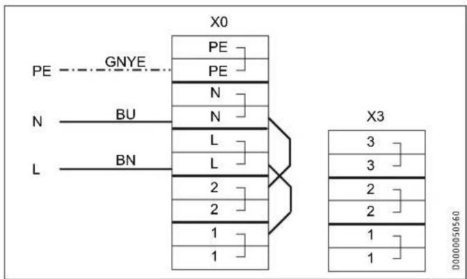
▶ Remove the jumper which leads from X0/N to X0/2 in the delivered condition.
▶ Remove the jumper which leads from X0/L to X0/1 in the delivered condition.
A Power supply provided by power supply utility or energy management system for switching the load (compressor)
B Power supply to impressed current anode and PCB
BN Brown
BU Blue
GNYE Green/yellow
- Connect the cables for the separate power supply to the impressed current anode to X0/1 and X0/2.

Material losses
The power supply to the impressed current anode must be ensured at all times.
10.3.3 Connection with external signal transmitter

Note
The appliance has a second, higher set temperature which is preset at the factory. This is activated when there is an external switching signal. Set temperature 2 takes priority over the standard set temperature while there is an external switching signal.
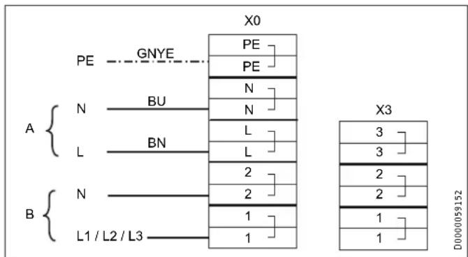
An external signal transmitter for switching a separate set DHW temperature (set temperature 2) can be connected to terminal X3/1-2. In the delivered condition, terminal X3/1-2 is not assigned. If this terminal is connected at the voltage stated in the specification (see "Permissible voltage range, external signal transmitter") (L to X3/1, N to X3/2), the appliance activates set temperature 2.
Following a one-off activation (signal is present for at least 1 minute), set temperature 2 applies for at least 20 minutes. Set temperature 2 takes priority over set temperature 1. When the relevant set DHW temperature has been reached, the compressor switches off and remains off for a minimum idle time of 20 minutes.
The following diagram illustrates the connections by means of a sample signal sequence from an external signal transmitter.
Example:
^S - Water temperature=62 °C
- Set temperature 1=61 °C
- Set temperature 2=65 °C
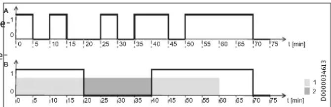
line
| Time (min) | Series A | Series B | |------------|----------|----------| | 0 | 1 | 1 | | 5 | 1 | 1 | | 10 | 1 | 1 | | 15 | 1 | 1 | | 20 | 1 | 0 | | 25 | 1 | 0 | | 30 | 1 | 0 | | 35 | 1 | 0 | | 40 | 1 | 0 | | 45 | 1 | 0 | | 50 | 1 | 0 | | 55 | 1 | 0 | | 60 | 1 | 0 | | 65 | 1 | 0 | | 70 | 1 | 0 | | 75 | 1 | 0 |A External signal
B Compressor
1 20 min. minimum runtime, set temperature 2
2 20 min. minimum compressor idle time

Note
An external signal must be present for at least 60 seconds before the control unit responds to it. For example, this will prevent a brief burst of sunshine from triggering a heat-up process which, in the absence of further sunlight, can no longer be covered using locally generated PV power.
▶ Remove the appliance cover (see chapter "Cleaning and maintenance / Removing the appliance cover").
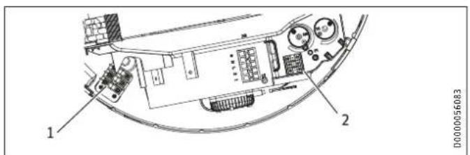
1 Strain relief
2 Terminal X3
▶ Prepare the cables in such a way that each cable terminates with a wire ferrule.
▶ Push the cables through one of the cable entries in the appliance casing.
▶ Route the cables through the strain relief.
▶ Connect the cables to X3.
Example 1: Power supply utility signal with its own phase
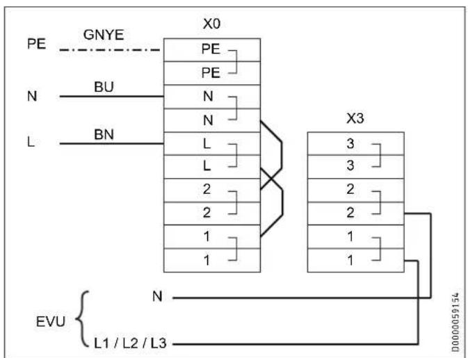
EVU Power supply utility
BN Brown
BU Blue
GNYE Green/yellow
Example 2: Photovoltaic signal via on-site relay and phase routed outside the appliance

Note
The relay in the inverter must meet the following requirements:
- Potential-free relay (240 V AC / 24 V DC, 1 A) with N/O contact
- Adherence to safety regulations and standards for safety extra low voltage
- The switching output must be able to be programmed such that the relay contact closes or opens if certain limits are exceeded or undershot (inverter output level).
If necessary, check with the inverter manufacturer whether the product meets the stated criteria.
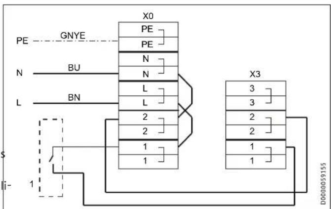
1 Inverter (floating contact)
BN Brown
BU Blue
GNYE Green/yellow
The inverter power feed is usually located at a central distribution point (e.g. in the main fuse box).
10.4 Assembling the appliance

Note
Refit the appliance cover after completing your work. See chapter "Maintenance and cleaning / Fitting the appliance cover").
11. Commissioning

WARNING Electrocution
Never operate the appliance when the casing is open or without a cover.
11.1 Initial start-up

Note
Fill the DHW cylinder before switching on the power supply to the appliance.
The appliance is equipped with boil-dry protection to prevent operation if the DHW cylinder is not completely full of water.

Note
Following an interruption to the power supply, compressor operation remains blocked for at least one minute. The PCB delays the electrical start-up by one minute, during which the appliance initialises. If the compressor subsequently fails to start, it may be locked out by additional safety devices (motor overload relay and high pressure switch). This lockout should be cleared after 1 to 10 minutes.
Fill the DHW cylinder and vent the pipework by following the procedure below:
▶ Close the drain valve.
▶ Open all DHW draw-off points and the shut-off valve in the cold water supply.
▶ Close the DHW draw-off points as soon as water comes out of them.
▶ Check the safety valve by leaving it open until water runs on
11.1.2 Settings / function check
▶ Switch the power supply ON.
▶ Check the appliance function.
▶ Check the function of the safety assembly.
After completing the function check, reducing the set DHW temperature helps to save energy.
▶ Establish the customer's comfort requirements and adjust the set DHW temperature accordingly. For hygiene reasons, do not set a DHW temperature of less than 61 °C (see section "Set temperature 1" on page 10 and "Set temperature 2" on page 10). Also ensure compliance with the legislation in force at the installation location.
11.1.3 Appliance handover
Explain the appliance function to users and familiarise them with how it works.
▶ Make users aware of potential dangers, especially the risk of scalding.
▶ Make users aware of critical environmental factors and requirements concerning the installation site.
▶ Inform users that water may drip from the safety valve during the heat-up process.
▶ Please note that the appliance is not protected against frost and corrosion when it is disconnected from the power supply. At the factory, the appliance is fitted with rechargeable batteries that ensure the power supply to the impressed current anode in the case of a power failure. The batteries must be replaced every three years if the power supply is regularly interrupted by a switching contact or if there is inadequate security of supply. We recommend a maintenance contract for replacing the batteries.
▶ Hand over these operating and installation instructions to users for safekeeping.
11.2 Recommissioning

Note
Following an interruption to the power supply, compressor operation remains blocked for at least one minute. The PCB delays the electrical start-up by one minute, during which the appliance initialises.
If the compressor subsequently fails to start, it may be locked out by additional safety devices (motor overload relay and high pressure switch). This lockout should be cleared after 1 to 10 minutes.
If the appliance is switched off due to an interruption to the power supply, no specific measures for restarting are required once the power supply has been restored.
If the "Rapid/comfort heat-up" function was active before the power supply interruption, it is re-enabled with a set temperature of 65 °C once the power supply has been restored.
Emergency mode is not reactivated after an interruption to the power supply.
12. Settings
Service menu
Material losses ! Service menu settings shall only be accessed with prior approval from Stiebel Eltron.
To unlock the service menu, you need to connect a service plug or enter a code.
Accessing the service menu with a service plug
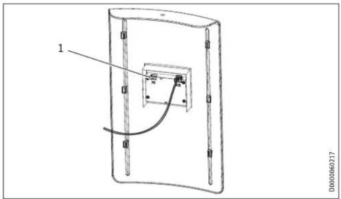
1 Slot X1
▶ Plug the service plug into slot X1 on the back of the programmed up, without any DHW being drawn-off.
ming unit.
Accessing the service menu by entering a code
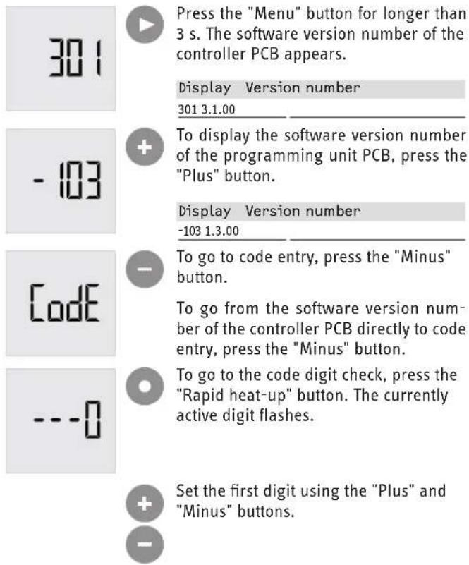

To set the next digit, press the "Rapid heat-up" button.
To confirm the code after entering all digits, press the "Rapid heat-up" button.
| Service menu |
| ☐ Integral sensor offset |
| ☐ Set the cylinder volume |
| ☐ Compressor lockout due to evaporator fault |
| ☐ Clear high pressure lockout |
| ☐ Clear low pressure lockout |
| ☐ Temperature of evaporator fins |
| ☐ Number of times hot gas temperature sensor was triggered |
| ☐ Number of defrost faults |
| ☐ Number of low pressure triggers |
| ☐ Number of high pressure triggers |
| ☐ Hot gas temperature switching value |
| ☐ Fan lead time |
| ☐ Integral sensor replacement |
| ☐ Set value limit |
The parameters in this menu are reserved for qualified contractors.
□■ Integral sensor offset
You can manually calibrate the integral sensor with the value set. This should only be done after the DHW cylinder has been fully heated up, without any DHW being drawn-off.
Example: The configured, active set temperature is 55 °C. The integral sensor of the appliance checks when the set temperature is reached. If the compressor switches off after heat-up, check the actual temperature (detected by the cylinder top sensor) using the programming unit. If the actual temperature is 60 °C, for example, set the integral sensor offset to 5 K.
Cylinder top sensor temperature = integral sensor temperature + offset
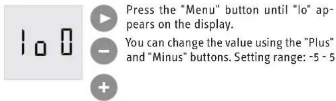
□ Set the cylinder volume
The cylinder size is required for accurate calculation of the mixed water volume. You can switch the cylinder size between 200 and 300 l using the "Plus" and "Minus" buttons.
If the PCB has been replaced, you will need to set the cylinder size.
If you see the value 9999 in the cylinder size parameter, you must select a suitable cylinder size for the appliance.
■ □ Compressor lockout due to evaporator fault
This menu item is only displayed if there is a compressor lockout due to fault code E 64. You can clear the lockout by pressing the "Rapid heat-up" button or performing a power ON reset.
■ □ Clear high pressure lockout
The appliance will be locked out if the high pressure sensor responds 5 times within 5 hours.
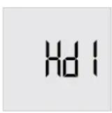

To clear the high pressure lockout, press the "Rapid heat-up" button.
■ □ Clear low pressure lockout
The appliance will be locked out if the low pressure sensor responds 5 times within 5 hours. This menu item allows you to clear the lockout.

Note
Currently appliances are built without low pressure sensors.
▶ If this lockout arises, check the jumper on the PCB (X0/L - X1/6 - A1/X2/ND).


To clear the low pressure lockout, press the "Rapid heat-up" button.
■ □ Temperature of evaporator fins
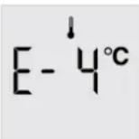
The temperature measured by a sensor on the evaporator fins is displayed here.
■ □ Number of times hot gas temperature sensor was triggered
The counter indicates how often the hot gas temperature has exceeded the set hot gas temperature switching value during heat-up.
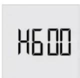
To reset the counter to 0, press the "Rapid heat-up" button.
■ □ Number of defrost faults
The number of defrost faults is displayed here. A defrost fault occurs if the temperature for terminating defrosting, as measured at the temperature sensor between the evaporator fins, has not been reached within the specified time frame.


To reset the counter to 0, press the "Rapid heat-up" button.
■ □ Number of low pressure triggers


To reset the counter to 0, press the "Rapid heat-up" button.
■ □ Number of high pressure triggers


To reset the counter to 0, press the "Rapid heat-up" button.
■ □ Hot gas temperature switching value

Material losses
Factory default setting:105 °C
Only a service technician is permitted to change his parameter in line with factory instructions.
If the set hot gas temperature switching value is exceeded, the hot gas temperature counter increments and the set temperature is temporarily reduced to the temperature captured by the integral sensor.


Press the "Menu" button until "h" appears on the display.
You can change this value using the "Plus" and "Minus" buttons. Setting range: 100 -120 °C

Example: The set temperature is 65 °C. At an actual temperature of 61 °C, for example due to a critical intake temperature, the appliance detects an unacceptably high hot gas temperature. The appliance temporarily reduces the set temperature to 61 °C. The appliance shuts down. Once the charge level has been under-shot (this refers to the currently applicable set value, i.e. 61 °C and not 65 °C), and when the hot gas temperature has dropped again, the compressor restarts and operates with the original set temperature (65 °C). The set temperature is reduced again if the appliance cannot reach this set temperature because the hot gas temperature was previously too high.
Fan lead time

Material losses
Factory default setting: 30 s
Only a service technician is permitted to change his parameter in line with factory instructions.
The set value specifies the number of seconds the fan runs before the compressor is enabled.
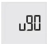

Press the "Menu" button until "u" appears on the display.

can change this value using the "Plus" and "Minus" buttons.

Replacement sensor
If the integral sensor is faulty, switch this parameter to replacement sensor operation using the "Plus" button.
When replacement sensor operation is active, fault 4 is permanently hidden. The default display shows the cylinder top temperature instead of the mixed water volume.
IE 0 Standard mode
IE 1 Replacement sensor active
Set value limit
If set value limiting is active, the lower end of the setting range for the set value is limited to 61 °C. If set value limiting is inactive, the set value can be adjusted to any value within the applicable range (see Set value1/Set value2).
Lt 0 Standard mode
Lt 1 Set value limiting active
13. Appliance shutdown

Material losses
If you disconnect the appliance from the power supply, it is no longer protected against frost or corrosion.
▶ Only disconnect the appliance from the power supply for longer periods if you are also draining the DHW cylinder. See chapter "Maintenance / Draining the appliance".
The appliance can only be switched off by interrupting the power supply.
▶ Disconnect the appliance from the power supply at the fuse in the distribution board or by unplugging the power plug if the appliance is connected to a socket.
14. Troubleshooting

WARNING Electrocution
Troubleshooting must only be carried out by a qualified contractor. Prior to all work on the appliance, isolate it from the power supply.

Material losses
If you disconnect the appliance from the power supply, it is no longer protected against frost or corrosion.
▶ Only disconnect the appliance from the power supply for longer periods if you are also draining the DHW cylinder.
▶ For work inside the appliance, remove the appliance cover (see chapter "Cleaning and maintenance / Removing the appliance cover").
▶ If necessary, remove the upper section of the casing jacket (see chapter "Maintenance and cleaning / Removing the casing ring").

Note
Refit the casing ring after completing the work. See chapter "Maintenance and cleaning / Fitting the casing ring").

Note
| Refit the appliance cover after completing your work. See chapter "Maintenance and cleaning / Fitting the appliance cover").

Note
Following an interruption to the power supply, compressor operation remains blocked for at least one minute while the appliance initialises.
If the compressor subsequently fails to start, it may be blocked by additional safety devices (motor overload relay, high pressure switch). This lockout can last between 1 and 10 minutes.
| Fault Cause | ▶ Remedy | |
| No hot water is available. | The impressed current anode is faulty. | Replace the impressed current anode. |
| The compressor is switched off unexpectedly. | The application limits have been exceeded or undershot. | No action required. |
| Excessive pressure in the refrigerant circuit. The safety pressure limiter has responded 5 times in 5 hours. The compressor has been switched off. | Eliminate the cause of the increased pressure in the refrigerant circuit. Wait approx. 5-15 minutes for the appliance to equalise the pressure. The appliance lockout can only be cleared using a service programming unit. | |
| The heating output of the appliance has reduced. | An inadequate air flow across the evaporator is a possible cause. | Check whether the fan is dirty. Check whether the evaporator is dirty. Ensure that the supply and extract air flow are unimpeded. |
14.1 Fault codes
| Fault description Remedy | |||
| 2 | Continuously on | The cylinder top sensor is faulty. The actual temperature display switches from the cylinder top sensor to the integral sensor. The appliance continues to heat without any loss of comfort. The mixed water volume cannot be calculated and is displayed as "-" . | Check that the plug is seated correctly. |
| Measure the resistance of the sensor and compare it with the resistance table. | |||
| Install the replacement sensor. | |||
| 4 | Continuously on | The integral sensor is faulty. In the event of a faulty integral sensor, the integral sensor is set to the value of the cylinder top sensor, and the mixed water volume is calculated using this value. The appliance continues to heat with a reduced start hysteresis. A mixed water volume is still calculated, based on the assumption that the cylinder top temperature is reached throughout the DHW cylinder. | Check that the plug is seated correctly. |
| Measure the resistance of the sensor and compare it with the resistance table. | |||
| Install the replacement sensor. In the service menu, use parameter "IE" to switch to standby mode. | |||
| 6 | Flashing | The cylinder top sensor and the integral sensor are faulty. The appliance no longer delivers heat. | Check that the plug is seated correctly. |
| Measure the resistances of the sensor and compare them with the resistance table. | |||
| Install the replacement sensor. In the service menu, use parameter "IE" to switch to standby mode. | |||
| Fault description Remedy | |||
| 8 | Flashing | The appliance has ascertained that the DHW cylinder has not been heated within the maximum temperature increase time, despite there being a demand. | Check if a DHW circulation line is installed and whether it is insulated. The total output loss is greater than the heating output of the appliance.Check if a DHW circulation pump is installed and whether it is controlled according to temperature or time. If necessary, install a corresponding control unit.Check the refrigerant circuit for leaks. |
| 16 | Continuously on | A short circuit of the impressed current anode has occurred or the protective anode is faulty. | Check the cables and relevant plug-in connections of the impressed current anode according to the connection diagram and replace faulty cables.Check the impressed current anode in the heating element/ anode assembly and replace if necessary. |
| 32 | Flashing | The appliance is not being operated with a completely filled DHW cylinder. The appliance is not heating. | Fill the DHW cylinder of the appliance. The fault code disappears and the appliance starts. |
| The anode current is interrupted. The appliance is not heating. | Check the contacts of the impressed current anode. | ||
| 64 | Continuously on | The defrost temperature has not yet been reached after the maximum defrost time has elapsed. The compressor is not working. | Check the position of the evaporator sensor in the evaporator. |
| The temperature of the intake air is below the lower application limit. | Wait for higher ambient temperatures. Ensure that the application limit is not undershot. | ||
| 128 | Continuously on | There is no communication between the controller and the programming unit. The most recently selected set values are active. The appliance continues to heat. | Check that the plug is seated correctly and replace the connecting cable if necessary. |
| Replace the programming unit PCB. | |||
| 256 | Flashing | Manually activated emergency mode (only electric emergency/booster heater active) | See chapter “Appliance description / Emergency mode”. |
| E 1 | Flashing | The temperature sensor on the air inlet is faulty. | Check that the plug is seated correctly.Measure the resistance of the sensor and compare it with the resistance table. |
| Replace the sensor. | |||
| E 2 | Flashing | The temperature sensor on the evaporator is faulty. | Check that the plug is seated correctly.Measure the resistance of the sensor and compare it with the resistance table. |
| Replace the sensor. | |||
| E 4 | Continuously on | The hot gas temperature sensor is faulty. The appliance continues to heat. To protect the appliance, the (possibly higher) set temperature is reduced to the set value for setback. | Check that the plug is seated correctly.Measure the resistance of the sensor and compare it with the resistance table. |
| Replace the sensor. | |||
| E 16 | Continuously on | The high pressure switch has responded. Compressor heating mode is temporarily blocked. Compressor heating mode will continue as soon as the pressure has normalised. | No action required. |
| After consultation with the customer, reduce the set temperature if required. Increase the charge level with the programming unit. | |||
| Check the offset of the integral sensor to the cylinder top sensor and adjust if necessary. | |||
| Check the high pressure switching point and replace the high pressure switch if necessary. | |||
| E 32 | Continuously on | An electrical fault has occurred. | A1/X2:Check whether the power supply has been interrupted. Then reset the fault with the corresponding menu option. |
| E 64 | Flashing | Evaporator temperature < Minimum evaporator temperature | Check whether the evaporator is clogged with deposits. If required, clean the evaporator with clear water without cleaning agents or other additives. |
| Check whether air can flow freely through the appliance. | |||
| Check whether the fan is blocked or faulty. Replace the fan if necessary. | |||
| Check the function and setting of the expansion valve. | |||
| Check whether the appliance has | defrosted. | ||
| E 128 | Flashing | A permanent pressure switch fault has occurred. A pressure fault occurred multiple times within a defined pressure fault evaluation time. | Check the relevant fault counter and look up the corresponding fault code remedy: E 16 (high pressure), E 32 (electrical wiring fault). Once the cause of the fault has been eliminated, clear the fault code in menu item "Hd 1" by pressing the "Rapid heat-up" button. |
14.2 Resetting the safety pressure limiter
The safety pressure limiter responds in the event of unacceptably high pressure in the refrigerant circuit. If the safety pressure limiter responds 5 times in 5 hours, compressor operation is blocked.
▶ Eliminate the cause of the increased pressure in the refrigerant circuit.
▶ Wait approx. 5-15 minutes for the appliance to equalise the pressure.
The appliance lockout can only be cleared using a service programming unit.
14.3 WWK 222 H / WWK 302 H: Resetting the high limit safety cut-out
If the DHW cylinder is overheated, the high limit safety cut-out switches off the electric emergency/booster heater to protect the appliance.
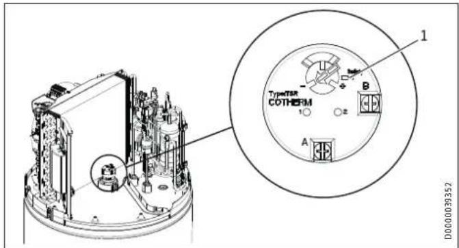
1 Reset button for high limit safety cut-out
▶ Once the cause of the fault has been removed, press the reset button of the high limit safety cut-out on the rod thermostat. To do so, remove the appliance cover.
14.4 Motor overload relay
The motor overload relay will shut down the compressor if it is overloaded because of excessive thermal load.
▶ Remove the cause.
After a short cooling period, the motor overload relay will restart the compressor automatically.
15. Maintenance

WARNING Electrocution
Prior to all work on the appliance, isolate it from the power supply.
15.1 Removing the appliance cover
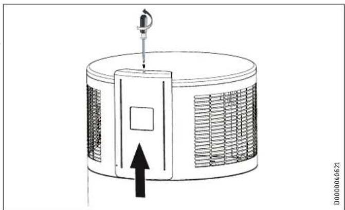
natural_image
Diagram of a cylindrical device with internal heat exchanger and upward arrow, no text or symbols present▶ Undo the screw (Torx) that secures the programming/control cover to the appliance.
▶ Push the programming/control cover upwards.
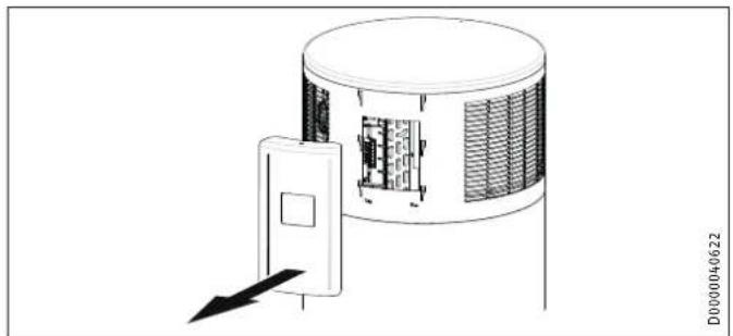
natural_image
Technical line drawing of a cylindrical device with a door and internal panel, no visible text or symbols▶ Carefully remove the cover.
▶ A cable connects the operating controls to the appliance PCB. The casing ring overlaps along the joint. A tab on one end clips if necessary, disconnect the plug at the back of the program- into the recess at the other end of the casing ring.
▶ Undo the plug-in connection in the cable that runs to the battery pack at the back of the cover.
▶ Carefully lift away the appliance cover and release the earth cable that runs from the appliance control panel to the cover.
The casing ring overlaps along the joint. A tab on one end clips into the recess at the other end of the casing ring.
▶ Ease the casing ring apart, until it can be removed or slid downwards.
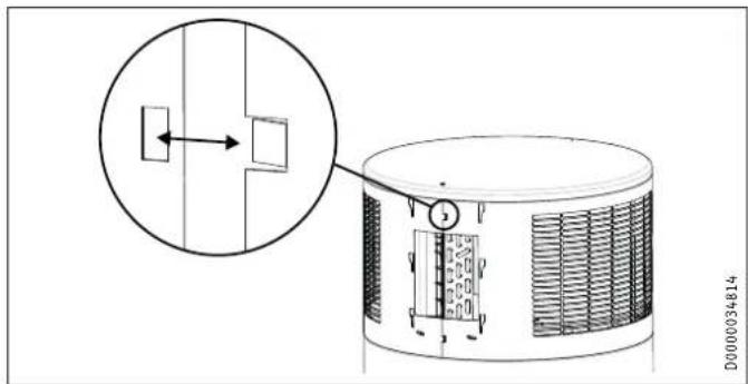

Note
Refit the casing ring after completing the work. See chapter "Maintenance and cleaning / Fitting the casing ring").

Note
Refit the appliance cover after completing your work. See chapter "Maintenance and cleaning / Fitting the appliance cover").
15.2 Removing the casing ring

Note
If you require more space to work inside the appliance, you can remove the casing ring on the upper section of the appliance.
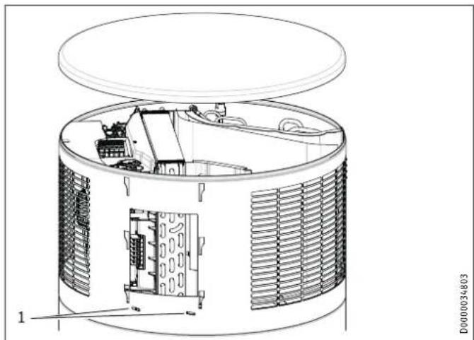
natural_image
Technical line drawing of a cylindrical industrial or electrical enclosure with internal components and ventilation grilles (no text or symbols)1 Fixing screws on casing ring
The casing ring is fastened with screws.
▶ Undo the fixing screws on the casing ring.
▶ Remove the condensate drain bend and pipe collar of the drain. Turn anti-clockwise to release.

Material losses
Inside the appliance, an earth cable is connected to the casing ring. Release the earth cable in order to be able to remove the casing ring.
15.3 Cleaning the evaporator

WARNING Injury
The evaporator consists of numerous sharp-edged fins.
▶ Be careful when cleaning the evaporator and wear protective clothing, especially safety gloves.
To keep the appliance performance levels as high as possible, check and clean the appliance evaporator as often as necessary.
▶ Undo the screw that fastens the appliance cover to the top of the programming/control cover.
▶ Remove the programming/control cover and the appliance cover.
▶ Carefully clean the evaporator fins. Only use water and a soft brush for this. Never use acidic or alkaline cleaning agents.
15.4 Draining the cylinder

WARNING Burns
Hot water may escape when draining the DHW cylinder.
To drain the DHW cylinder, e.g. when shutting the appliance down, proceed as follows.
▶ Isolate the appliance from the power supply.
▶ Close the shut-off valve in the cold water supply line.
The DHW cylinder is drained via the cold water supply line.
▶ Open the drain valve installed in the cold water supply line (see chapter "Water connection"). If no drain valve has been installed, undo the cold water supply line at the "Cold water inlet" connection.
▶ To vent the system, undo the DHW line connected to the "DHW outlet" connection.
Some residual water will remain in the bottom of the DHW cylinder.
15.5 Descaling the electric emergency/booster heater
Only descale the flange of the emergency/booster heater after disassembly. Never treat the inside of the DHW cylinder or the impressed current anode with descaling agents. The electric emergency/booster heater is screwed into the DHW cylinder of the appliance at a central point at the top.
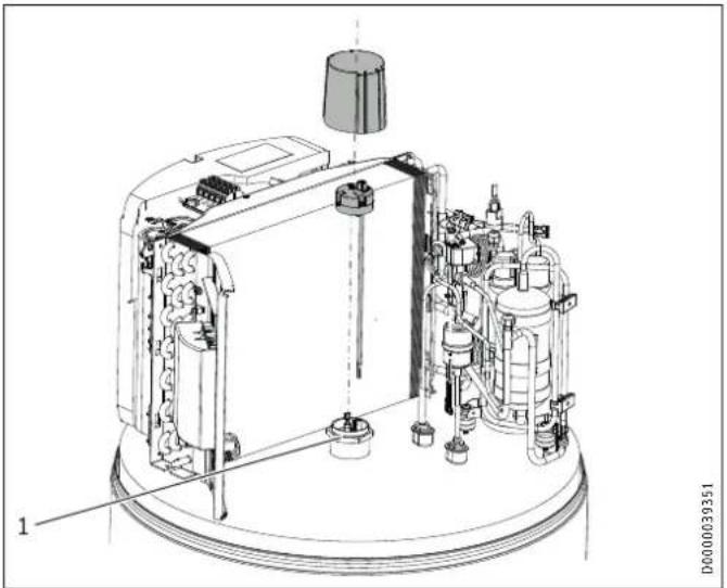
natural_image
Technical line drawing of an industrial equipment assembly with labeled components (no readable text or symbols)1 Electric emergency/booster heater with protective anode
15.6 Valves
Regularly check the valves in the system (safety valve, pressure reducing valve, drain valve) to ensure the operational reliability of the appliance. The amount of limescale deposits depends on the local water quality.
▶ Check all valves in the system and remove limescale deposi
▶ Replace the valves if necessary.
▶ Check the function of the valves.
15.7 Condensate drain
▶ Check whether the condensate drain is clear of obstructions ^a
Remove any dirt.
15.8 Replacing the power cable

WARNING Electrocution
The power cable must only be replaced (for example if damaged) by a qualified contractor.
15.9 Fitting the casing ring

WARNING Electrocution
▶ Reconnect the earth cable to the casing ring.
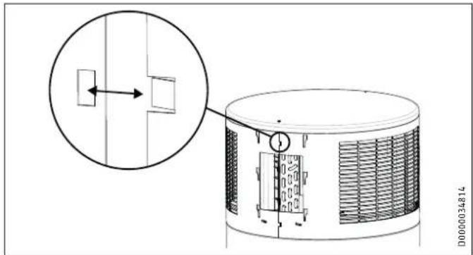
▶ Fit the upper casing ring. The casing ring overlaps along the joint. A tab on one end clips into the recess at the other end of the casing ring.
▶ Secure the casing ring with screws.
▶ Fit the pipe collar of the condensate drain and the condensate drain bend.
15.10 Protective anode and battery change
The appliance is equipped with a maintenance-free impressed current anode that protects the cylinder from corrosion when it is connected to the power supply. At the factory, the appliance is fitted with rechargeable batteries that ensure the power supply to the impressed current anode in the case of a power failure. The appliance power supply must not be interrupted for more than 16 hours.
its the power supply is regularly interrupted by a switching contact or the security of supply is inadequate, the batteries of the impressed current anode must be replaced every three years. Failure to comply may result in damage to the appliance. If regular interruptions to the power supply are not anticipated and there is security of supply, no maintenance of the batteries is required and the appliance is maintenance-free in this regard.

Material losses
Never use batteries that cannot be charged. Only rechargeable NiMH batteries are permissible.
Batteries may be damaged in the appliance. Without a power supply, the impressed current anode and the cylinder would not be protected against corrosion.
The batteries are secured at the back of the programming/control cover.
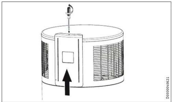
natural_image
Diagram of a cylindrical device with heat exchanger and sensor, showing internal structure and directional arrow (no text or symbols)▶ Undo the screw securing the cover.
▶ Carefully remove the cover so that the cables running from the batteries to the impressed current anode in the appliance are not pulled out.
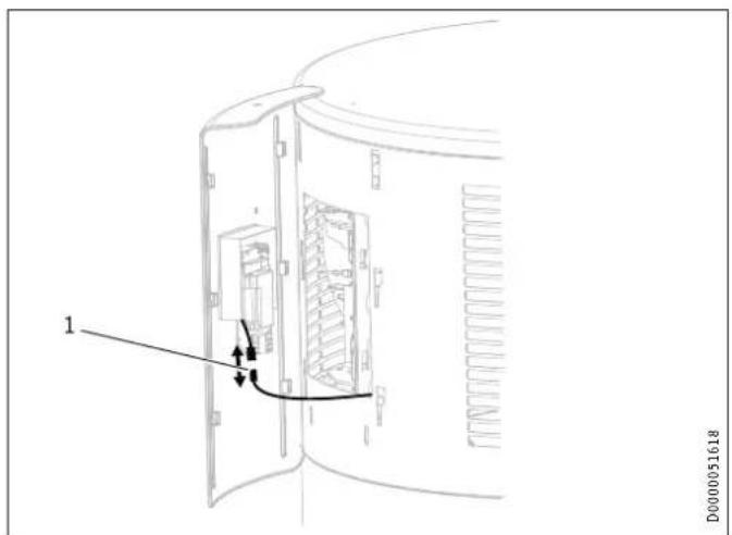
1 Plug-in connection
▶ Undo the plug-in connection by pressing the catches on both sides.
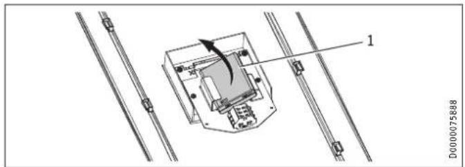
1 Battery compartment
▶ Carefully pull the battery compartment on the right-hand side forward.
▶ Remove the battery compartment from the retainer.
▶ Open the battery compartment using a screwdriver.
▶ Replace the batteries (NiMH, type AAA ≥ 800 mAh).

Material losses
Make sure that the batteries are inserted properly and the right way round, because otherwise there will be no corrosion protection in the event of interruptions to the power supply.
▶ Close the battery compartment using a screwdriver.
▶ Push the battery compartment into the retainer.
▶ Reconnect it to the appliance with the plug-in connection.
15.11 Fitting the appliance cover

WARNING Electrocution
▶ Reconnect the earth cable to the appliance cover.
▶ Place the cover back on the appliance.
▶ Press the cover into the bead around the casing ring.
▶ Connect the cable linking the batteries with the internal control unit at the back of the programming/control cover.
▶ Connect the cable linking the programming unit to the PCB inside the appliance at the back of the programming/control cover.
▶ Insert the programming/control cover.
▶ Use the screw to secure the programming/control cover at the top of the appliance.
16. Specification
16.1 Dimensions and connections
16.1.1 WWK 222/WWK 222 H
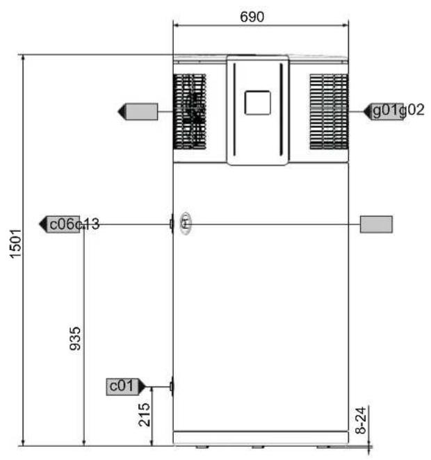
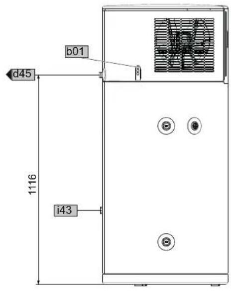
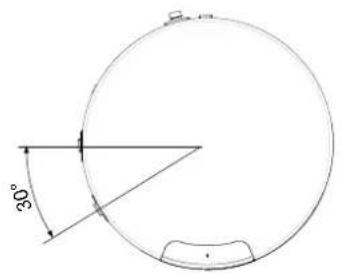
D0000074176
| WWK 222 WWK 222 H | ||||
| b01 | Entry electrical cables | |||
| c01 | Cold water inlet | Male thread | G 1 | G 1 |
| c06 | DHW outlet | Male thread | G 1 | G 1 |
| c13 | T&P valve | Female thread | Rp 3/4 | Rp 3/4 |
| d45 | Condensate drain | Male thread | G 3/4 | G 3/4 |
| g01 | Air intake | |||
| g02 | Air discharge | |||
| i43 | Cover for manufacturing aperture | |||
16.1.2 WWK 302/WWK 302 H
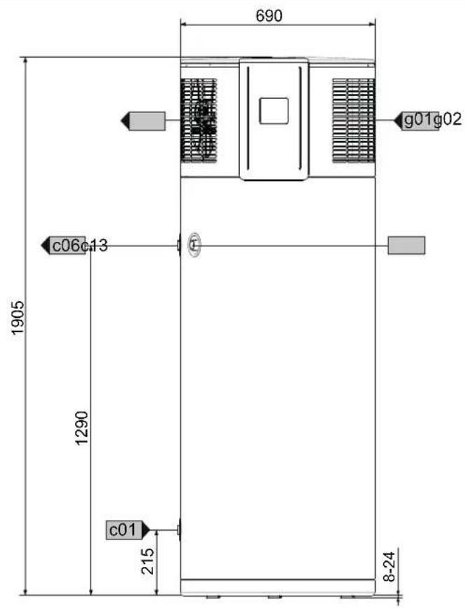
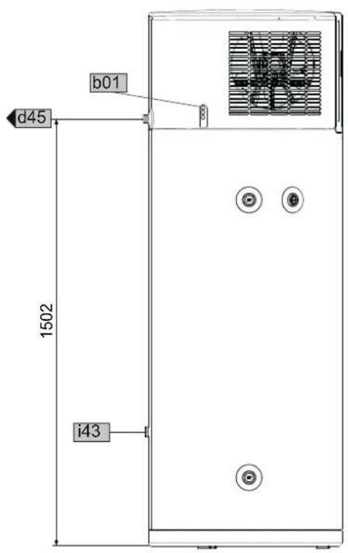
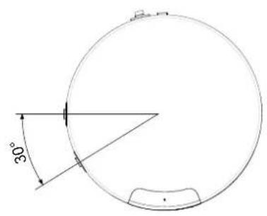
D0000074178
| WWK 302 | WWK 302 H | |||
| b01 | Entry electrical cables | |||
| c01 | Cold water inlet | Male thread | G 1 | G 1 |
| c06 | DHW outlet | Male thread | G 1 | G 1 |
| c13 | T&P valve | Female thread | Rp 3/4 | Rp 3/4 |
| d45 | Condensate drain | Male thread | G 3/4 | G 3/4 |
| g01 | Air intake | |||
| g02 | Air discharge | |||
| i43 | Cover for manufacturing aperture | |||
16.2 Wiring diagram
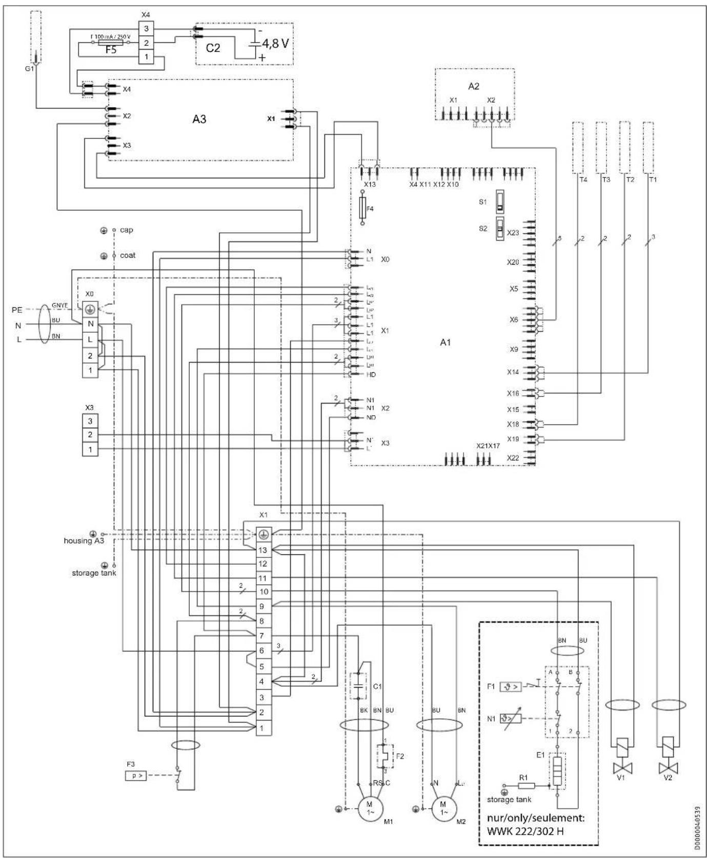
A1 Electronic assembly (control unit)
A2 Electronic assembly (programming unit)
A3 Electronic assembly (electrical corrosion protection)
C1 Capacitor
C2 Battery pack
E1 Heating element
F1 High limit safety cut-out TSR
F2 Motor overload relay M1
F3 High pressure switch
F4 Fuse
F5 Fuse
G1 Impressed current anode
M1 Compressor
M2 Fan
16.3 Fault conditions

WARNING Burns
In the case of a fault, temperatures up to the high limit safety cut-out limit can occur (see chapter "Specification / Data table").
N1 Thermostat TSR
R1 Resistor
S1 DIP switch (operating mode)
S2 DIP switch
T1 Temperature sensor cylinder top/int.
T2 Temperature sensor, hot gas
T3 Temperature sensor, air intake
T4 Temperature sensor, evaporator
V1 Solenoid valve (live in heating mode)
V2 Solenoid valve (live in defrost mode)
X0 Mains terminal
X1 Terminal
X3 Terminal
X4 Terminal, battery pack
16.4 Data table
| WWK 222 WWK 222 H WWK 302 WWK 302 H | |||||
| 231209 | 233209 | 231211 | 232905 | ||
| Hydraulic data | |||||
| Nominal capacity | I | 220 | 220 | 302 | 302 |
| Application limits | |||||
| DHW temperature with heat pump | °C | 61 | 61 | 61 | 61 |
| Max. DHW temperature with heat pump | °C | 65 | 65 | 65 | 65 |
| Max. DHW temperature with emergency/booster heater | °C | 65 | 65 | 65 | 65 |
| High limit safety cut-out | °C | 92 | 92 | 92 | 92 |
| Min./max. application limits of heat source for heat pump operation | °C | -5/+42 | -5/+42 | -5/+42 | -5/+42 |
| Min./max. application limits for cylinder ambient temperature | °C | -5/+55 | -5/+55 | -5/+55 | -5/+55 |
| Min. installation room volume (recirculation air mode, general domestic use) | m3 | 13 | 13 | 13 | 13 |
| Max. permissible operating pressure, cold water/DHW | MPa | 0.85 | 0.85 | 0.85 | 0.85 |
| Min./max. conductivity, potable water | μS/cm | 100-1500 | 100-1500 | 100-1500 | 100-1500 |
| Annual Average Coefficient of Performance (Australia) | |||||
| ACOP (AS/NZS 4234 | climate zone 2 | medium load) | 3.94 | 3.94 | 3.58 | 3.58 | |
| Values | |||||
| Temperature setting range, DHW | °C | 61-65 | 61-65 | 61-65 | 61-65 |
| Type of anode | Maintenance-freeimpressed currentanode | Maintenance-freeimpressed currentanode | Maintenance-freeimpressed currentanode | Maintenance-freeimpressed currentanode | |
| Air flow rate | m3/h | 550 | 550 | 550 | 550 |
| Recommended number of users | ≤4 | ≤4 | ≤6 | ≤6 | |
| Energy data | |||||
| DHW heating energy efficiency class (load profile), indoor air | A+ (L) | A+ (L) | A (XL) | A (XL) | |
| Output data to EN 16147 | |||||
| Nominal DHW temperature (EN 16147) | °C | 61 | 61 | 61 | 61 |
| Nominal load profile (EN 16147) | L | L | XL | XL | |
| Heating output | |||||
| Average heating output (A15 / W10-55) | kW | 1.6 | 1.6 | 1.6 | 1.6 |
| Power consumption | |||||
| Average power consumption of heat pump (A15 / W10-55) | kW | 0.5 | 0.5 | 0.5 | 0.5 |
| Max. heat pump power consumption (excl. start-up) | kW | 0.65 | 0.65 | 0.65 | 0.65 |
| Power consumption, emergency/booster heater | kW | 1.5 | 1.5 | ||
| Max. power consumption, heat pump + emergency/booster heater | kW | 2.2 | 2.2 | ||
| Electrical data | |||||
| Rated voltage | V | 230 | 230 | 230 | 230 |
| Power supply | 1/N/PE 220-240 V50/60 Hz | 1/N/PE 220-240 V50/60 Hz | 1/N/PE 220-240 V50/60 Hz | 1/N/PE 220-240 V50/60 Hz | |
| Permissible voltage range, external signal transmitter | ~220-240 V 50/60Hz | ~220-240 V 50/60Hz | ~220-240 V 50/60Hz | ~220-240 V 50/60Hz | |
| Max. operating current | A | 3.18 | 9.7 | 3.18 | 9.7 |
| Max. starting current | A | 15.4 | 23.44 | 15.4 | 23.44 |
| Fuse protection | A | C10 | C16 | C10 | C16 |
| Sound emissions | |||||
| Sound power level (EN 12102) | dB(A) | 60 | 60 | 60 | 60 |
| Average sound pressure level at 1 m distance, free field | dB(A) | 45 | 45 | 45 | 45 |
| Versions | |||||
| IP rating | IP 24 | IP 24 | IP 24 | IP 24 | |
| Refrigerant | R134a | R134a | R134a | R134a | |
| Refrigerant charge | kg | 0.85 | 0.85 | 0.85 | 0.85 |
| Global warming potential of the refrigerant (GWP100) | 1430 | 1430 | 1430 | 1430 | |
| CO2 equivalent (CO2e) | t | 1,216 | 1,216 | 1,216 | 1,216 |
| Power cable length approx. | mm | 2000 | 2000 | 2000 | 2000 |
| Dimensions | |||||
| Height | mm | 1501 | 1501 | 1905 | 1905 |
| Diameter | mm | 690 | 690 | 690 | 690 |
| Height when tilted | mm | 1652 | 1652 | 2026 | 2026 |
| Height when tilted incl. packaging | mm | 1895 | 1895 | 2230 | 2230 |
| Packing unit dimensions height/width/depth | mm | 1740/740/740 | 1740/740/740 | 2100/740/740 | 2100/740/740 |
| Weights | |||||
| Weight, empty | kg | 120 | 120 | 135 | 135 |
| WWK 222 WWK 222 H WWK 302 WWK 302 H Connections | ||||
| Condensate connection G 3/4 G 3/4 G 3/4 G 3/4 | ||||
| Safety valve connection | Rp 3/4 | Rp 3/4 | Rp 3/4 | Rp 3/4 |
| Water connection | G 1 (with adaptor Rp 3/4 fem.) | G 1 (with adaptor Rp 3/4 fem.) | G 1 (with adaptor Rp 3/4 fem.) | G 1 (with adaptor Rp 3/4 fem.) |
The output data refers to new appliances with clean heat ex-changers.
Nominal data to EN 16147 - heat pump for recirculation air
16.5 Standardised output data
Information on determining and interpreting the specified standardised output data
Standard: EN 16147
The output data specifically mentioned in text, diagrams and technical datasheets has been determined in line with the test conditions described in the standard shown in the heading of this chapter.
Generally, these standardised test conditions will not fully meet the conditions found at the installation site of the system user. Depending on the chosen test method and the extent to which the selected method deviates from the conditions described in the standard shown in the heading of this chapter, any deviations can have a considerable impact. Additional factors that have an influence on the test values are the measuring equipment, the system configuration, the age of the system and the flow rates.
A confirmation of the specified output data can only be obtained if the conditions applicable to the relevant test match those of the standard shown in the heading of this chapter.
Guarantee
The guarantee conditions of our German companies do not apply to appliances acquired outside of Germany. In countries where our subsidiaries sell our products a guarantee can only be issued by those subsidiaries. Such guarantee is only granted if the subsidiary has issued its own terms of guarantee. No other guarantee will be granted.
We shall not provide any guarantee for appliances acquired in countries where we have no subsidiary to sell our products. This will not affect warranties issued by any importers.
Environment and recycling
We would ask you to help protect the environment. After use, dispose of the various materials in accordance with national regulations.
Warranty Stiebel Eltron Australia Only - According to national regulations in Australia
Warranty for Heat Pumps - Models WWK 222, WWK 222 H, WWK 302 and WWK 302 H
Who gives the warranty
- The warranty is given by Stiebel Eltron (Aust) Pty Ltd (A.B.N. 82 066 271 083) of 294 Salmon Street, Port Melbourne, Victoria, 3207 ("we", "us" or "our").
The warranty
- This warranty applies to Stiebel Eltron Heat Pumps - Models WWK 222, WWK 222 H, WWK 302 and WWK 302 H (the "unit") manufactured after 1 July 2015.
- Subject to the warranty exclusions we will repair or replace, at our absolute discretion, a faulty component in your unit free of charge if it fails to operate in accordance with its specifications during the warranty period.
- If we repair or replace a faulty component to your unit under this warranty, the warranty period is not extended from the time of the repair or replacement.
- The warranty period commences on the date of completion of the installation of the unit. Where the date of completion of installation is not known, then the warranty period will commence 2 months after the date of manufacture.
- The warranty period for a unit used for domestic purposes is shown in the table below. Domestic purposes means that the unit is used in a domestic dwelling.
| Component Warranty period | |
| Cylinder and condenser 5 years | |
| Sealed refrigeration system, including compressor, evaporator, valves and associated pipe work. All other electrical componentry. | 2 years |
| T&P relief valve 1 year |
- The warranty period for a unit used for commercial purposes is shown in the table below. Commercial purposes means that the unit is used for a non-domestic purpose and includes but not limited to being used in a motel, hotel, mining camp or nursing home.
| Component Warranty period | |
| Cylinder and condenser 2 years | |
| Sealed refrigeration system, including compressor, evaporator, valves and associated pipe work. All other electrical componentry. | 2 years |
| T&P relief valve 1 year |
Your entitlement to make a warranty claim
- You are entitled to make a warranty claim if:
8.1. you own the unit or if you have the owner's consent to represent the owner of the unit;
8.2. you contact us within a reasonable time of discovering the problem with the unit;
How you make a warranty claim
- To make a warranty claim you must provide us with the following information:
9.1. The model number of the unit;
9.2. A description of the problem with the unit;
9.3. The name, address and contact details (such as phone number and e-mail address) of the owner;
9.4. The address where the unit is installed and the location (e.g. at side of house);
9.5. The serial number of the unit;
9.6. The date of purchase of the unit and the name of the seller of the unit;
9.7. The date of installation of the unit;
9.8. A copy of the certificate of compliance when the unit was installed. - The contact details for you to make your warranty claim are:
Name: Stiebel Eltron (Aust) Pty Ltd
Address: 294 Salmon Street, Port Melbourne, Victoria, 3207
Telephone: 1800 153 351 (8.00 am to 5.00 pm AEST Monday to Friday)
Contact person: Customer Service Representative
E-mail: service@stiebel.com.au
- We will arrange a suitable time with you to inspect and test the unit.
Warranty exclusions
- We may reject your warranty claim if:
12.1. The unit was not installed by a registered and qualified plumber.
12.2. The unit was not installed and commissioned:
a) in Australia;
b) in accordance with the Operating and Installation Guide; and
c) in accordance with the relevant statutory and local requirements of the State or Territory in which the unit is installed.
12.3. The unit has not been operated or maintained in accordance with the Operating and Installation Guide.
12.4. The unit does not bear its original Serial Number or Rating Label.
12.5. The unit was damaged by any or any combination of the following:
a) normal fair wear and tear;
b) connection to an incorrect water supply, for example, (but not limited to) connection to water from a bore, dam or swimming pool;
c) connection to an incorrect power supply;
d) connection to faulty equipment, such as damaged valves;
e) insufficient air flow;
f) foreign matter in the water supply, such as sludge or sediment;
g) corrosive or acidic elements in the water supply, where the Langelier Saturation Index (LSI) is outside the range -1.0 < LSI < 0.8;
h) inappropriate current impressed anode;
i) inappropriate current impressed anode battery maintenance;
j) accidental damage;
k) uncontrollable natural phenomena, including damage by flood, storm, fire, lightning strike and the like;
l) excessive water pressure, negative water pressure (partial vacuum) or water pressure pulsation; m) ingress of vermin.
12.6. The unit was damaged before it was installed e.g. it was damaged in transit.
12.7. An unauthorised person has modified, serviced, repaired or attempted to repair the unit without our consent.
12.8. Non genuine parts other than those manufactured or approved by us have been used on the unit.
- We may charge you:
13.1. for any additional transport costs if the unit is installed more than 30 kilometres from our closest authorised service technician.
13.2. for the extra time it takes our authorised service technician to access the unit for inspection and testing if it is not sited in accordance with the Operating and Installation Guide and not readily accessible for inspection.
13.3. for any extra costs of our authorised service technician to make the unit safe for inspection.
NOTES
Deutschland
www.stiebel-eltron.com.au
Austria
STIEBEL ELTRON Ges.m.b.H.
Plant C3, XEDA International Industry City
Xiqing Economic Development Area
300385 Tianjin
Tel. 022 8396 2077 | Fax 022 8396 2075
info@stiebeleltron.cn
www.stiebeleltron.cn
Czech Republic
STIEBEL ELTRON spol. s r.o.
61 Barrys Point Road | Auckland 0622
Tel. +64 9486 2221
info@stiebel-eltron.co.nz
www.stiebel-eltron.co.nz
Poland
STIEBEL ELTRON Polska Sp. z 0.0.
Urzhumskaya street 4,
building 2 | 129343 Moscow
Tel. +7 495 125 0 125
info@stiebel-eltron.ru
www.stiebel-eltron.ru
Slovakia
STIEBEL ELTRON Slovakia, s.r.o.
Hlavná 1 | 058 01 Poprad
Tel. 052 7127-125 | Fax 052 7127-148
info@stiebel-eltron.sk
www.stiebel-eltron.sk
Switzerland
STIEBEL ELTRON AG
Industrie West
Gass 8 | 5242 Lupfig
Tel. 056 4640-500 | Fax 056 4640-501
info@stiebel-eltron.ch
www.stiebel-eltron.ch
Thailand
STIEBEL ELTRON Asia Ltd.
469 Moo 2 Tambol Klong-Jik
Amphur Bangpa-In | 13160 Ayutthaya
Tel. 035 220088 | Fax 035 221188
info@stiebeleltronasia.com
www.stiebeleltronasia.com
United Kingdom and Ireland
STIEBEL ELTRON UK Ltd.
Unit 12 Stadium Court
Stadium Road | CH62 3RP Bromborough
Tel. 0151 346-2300 | Fax 0151 334-2913
info@stiebel-eltron.co.uk
www.stiebel-eltron.co.uk
United States of America
STIEBEL ELTRON, Inc.
17 West Street | 01088 West Hatfield MA
Tel. 0413 247-3380 | Fax 0413 247-3369
info@stiebel-eltron-usa.com
www.stiebel-eltron-usa.com

Irrtum und technische Änderungen vorbehalten! | Subject to errors and technical changes! | Sous réserve d'erreurs et de modifications techniques! | Onder voorbehoud van vergissingen en technische wijzigingen! | Salvo error o modificación técnica! | Excepto erro ou alteração técnica | Zastrzeżone zmiany techniczne i ewentualne błędy | Omyly a technické zmény jsou vyhrazeny! | A muszaki változtalások és tévedések jogát fenntartjuk! | Otcutствие ошибok ne гарантируется. Возможны технические изменения. | Chyby a technické zmény sü vyhradené! Stand 9646
STIEBEL ELTRON

- SPECIAL INFORMATION
- OPERATION
- INSTALLATION
- GUARANTEE
- ENVIRONMENT AND RECYCLING
- SpECIAL INFO mATION
- OpE ATION
- General information
- Note
- Safety instructions
- Structure of safety instructions
- Symbols, type of risk
- Keywords
- Other symbols in this documentation
- Units of measurement
- Safety
- Intended use
- General safety instructions
- WARNING Injury
- WARNING Electrocution
- WARNING Burns
- CAUTION Injury
- Material losses
- Test symbols
- Appliance description
- Heat pump operating principle
- DHW heating
- WWK 222 H | WWK 302 H : Electric emergency/booster heater
- Appliance operation outside the application limits
- Ambient temperatures below the application limit
- Active defrosting
- Ambient temperatures above the application limit
- Frost protection
- Minimum runtime and minimum pause time
- Connection of an external signal transmitter
- Settings
- Emergency shutdown
- Weatherproof cover
- Display and operating controls
- Symbols
- Symbol
- Description
- Adjusting the settings
- Menu
- □ ■ Set temperature 1
- Set temperature 2
- Operation with external signal transmitter
- Air intake temperature display
- Enabling the "Runtime-dependent rapid heat-up" function
- ■ □ Time set for the "Runtime-dependent rapid heat-up" function
- Change units
- Charge level
- Fault code
- E fault code
- "Rapid heat-up" button
- Rapid/comfort heat-up
- Emergency mode
- Manual emergency heating mode
- Cleaning, care and maintenance
- Protective anode and battery change
- Application scenarios for emergency heating mode
- Notifying a qualified contractor
- Safety
- General safety instructions
- Instructions, standards and regulations
- Appliance description
- Standard delivery
- Corners of the packaging
- Required accessories
- Additional accessories
- Incorrect use
- Preparation
- Transport
- Vehicular transport
- Transport from vehicle to installation room
- Storage
- Installation site
- Sound emissions
- Siting the appliance
- Cardboard packaging clips
- Metal bracket fixing screw
- Minimum clearances
- Installation
- Water connection
- Cold water line
- DHW line
- DHW circulation
- Safety equipment
- Safety valve (cold water expansion control valve)
- Pressure reducing valve
- Drain valve
- Thermal insulation
- DHW outlet
- Condensate drain
- Condensate pan heater
- Electrical connection
- Standard connection (without external signal transmitter)
- Separate power supply to the impressed current anode
- Connection with external signal transmitter
- Assembling the appliance
- Commissioning
- Initial start-up
- Settings / function check
- Appliance handover
- Recommissioning
- Settings
- Service menu
- □■ Integral sensor offset
- □ Set the cylinder volume
- ■ □ Compressor lockout due to evaporator fault
- ■ □ Clear high pressure lockout
- ■ □ Clear low pressure lockout
- ■ □ Temperature of evaporator fins
- ■ □ Number of times hot gas temperature sensor was triggered
- ■ □ Number of defrost faults
- ■ □ Number of low pressure triggers
- ■ □ Number of high pressure triggers
- ■ □ Hot gas temperature switching value
- Fan lead time
- Replacement sensor
- Set value limit
- Appliance shutdown
- Troubleshooting
- Resetting the safety pressure limiter
- WWK 222 H / WWK 302 H: Resetting the high limit safety cut-out
- Motor overload relay
- Maintenance
- Removing the appliance cover
- Removing the casing ring
- Fixing screws on casing ring
- Cleaning the evaporator
- Draining the cylinder
- Descaling the electric emergency/booster heater
- Valves
- Condensate drain
- Replacing the power cable
- Fitting the casing ring
- Protective anode and battery change
- Fitting the appliance cover
- Specification
- Dimensions and connections
- WWK 222/WWK 222 H
- Fault conditions
- Standardised output data
- Standard: EN 16147
- Warranty Stiebel Eltron Australia Only - According to national regulations in Australia
- Who gives the warranty
- The warranty
- Your entitlement to make a warranty claim
- How you make a warranty claim
- Warranty exclusions
- Deutschland
- Austria
- Czech Republic
- Poland
- Slovakia
- Switzerland
- Thailand
- United Kingdom and Ireland
- United States of America
- STIEBEL ELTRON
Brand : STIEBEL ELTRON
Model : WWK 222H
Category : Chauffe-eau instantané et ballon d'eau chaude