
DMX Power Splitter 4x4 - Professional lighting equipment Eurolite - Free user manual and instructions
Find the device manual for free DMX Power Splitter 4x4 Eurolite in PDF.


| Product Type | DMX Signal Splitter / Distributor |
| Brand | Eurolite |
| Model | DMX Power Splitter 4x4 |
| DMX Input | 1 x XLR 3-pin female |
| DMX Outputs | 4 x XLR 3-pin male (individually isolated) |
| Signal Regeneration | Yes, for each output |
| Galvanic Isolation | Yes, between outputs |
| Power Supply | 100-240V AC, 50/60 Hz (IEC inlet) |
| Power Consumption | Approx. 15 W |
| DMX Protocol | USITT DMX512-A |
| Number of Channels | 512 (pass-through) |
| LED Indicators | Power, DMX signal on each output |
| Housing | Metal, 19" rack-mountable (1U) |
| Dimensions | Approx. 482 x 44 x 150 mm |
| Weight | Approx. 1.5 kg |
| Operating Temperature | 0°C to 40°C |
| Protection Features | Overcurrent, reverse polarity, short circuit protection |
| Accessories Included | Power cord, user manual, mounting rack ears |
| Certifications | CE, RoHS |
| Warranty | 2 years (subject to terms) |
Frequently Asked Questions - DMX Power Splitter 4x4 Eurolite
User questions about DMX Power Splitter 4x4 Eurolite
0 question about this device. Answer the ones you know or ask your own.
Ask a new question about this device
Download the instructions for your Professional lighting equipment in PDF format for free! Find your manual DMX Power Splitter 4x4 - Eurolite and take your electronic device back in hand. On this page are published all the documents necessary for the use of your device. DMX Power Splitter 4x4 by Eurolite.
USER MANUAL DMX Power Splitter 4x4 Eurolite
No. 70064806 3-pin XLR No. 70064807 5-pin XLR
www.eurolite.de
INHALT
EINFÜHRUNG 3
Produktmerkmale 3
Lieferumfang 3
www.eurolite.de

www.youtube.com/eurolitevideo

www.facebook.com/Eurolitefans

1: Masse
2: Signal (−)
3: Signal (+)
4: NC
5: NC
DMX-Eingang
3-pol. XLR
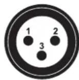
5-pol. XLR
1: Masse
2: Signal (−)
3: Signal (+)

1: Masse
2: Signal (-)
3: Signal (+)
4: NC
5: NC
CONTENTS
INTRODUCTION 10
Product features 10
What is included 10
IMPORTANT SAFETY INSTRUCTIONS ..... 11
PROTECTING THE ENVIRONMENT ...... 12
OPERATING ELEMENTS AND CONNECTIONS . 13
SETUP 14
Installation 14
DMX512 connection 14
Connection to the power supply 14
LED indicators 14
Select RDM filter mode 14
CLEANING AND MAINTENANCE 14
TECHNICAL SPECIFICATIONS .... 15
D00132105, version 1.0, publ. 08/12/2020
For product updates, documentation, software and support please visit www.eurolite.de. You can find the latest version of this user manual in the product's download section.
© 2020 Eurolite. All rights reserved.
No part of this document may be reproduced in any form without the written permission of the copyright owner. The contents of this document are subject to revision without notice due to continued progress in methodology, design, and manufacturing. Eurolite shall have no liability for any error or damage of any kind resulting from the use of this document.
All trademarks mentioned herein are the property of their respective owners.
INTRODUCTION
Experience Eurolite.
Product videos, suitable accessories, firmware and software updates, documentation and the latest news about the brand. You will find this and much more on our website. You are also welcome to visit our YouTube channel and find us on Facebook.

www.eurolite.de

www.youtube.com/eurolitevideo

www.facebook.com/Eurolitefans
Welcome to Eurolite! Thank you for choosing one of our products. Eurolite is your connection to the world of show with an unparalleled variety of products, both for professionals and beginners.
If you follow the instructions given in this manual, we are sure that you will enjoy this product for a long period of time. This user manual will show you how to install, set up and operate your new Eurolite product.
Users of this product are recommended to carefully read all warnings in order to protect yourself and others from damage. Please keep this manual for future needs and pass it on to further owners.
Product features
- 4 dimmer channels
• 1 P-Con input to 4 outputs, max. 16A
• 1 DMX input to 4 outputs
• 1 DMX feed-through output - Supports RDM
- Switchable RDM filter mode
- Switchable termination resistor
- Input and outputs galvanically isolated
• Each DMX output with independent driver and status indicator - Rack mounting
What is included
- Power splitter
- Mains cable
- This user manual
IMPORTANT SAFETY INSTRUCTIONS
CAUTION!

Operating conditions
This device has been designed for indoor use only. Keep this device away from rain and moisture.
DANGER!

Electric shock caused by short-circuit
Be careful with your operations. With a dangerous voltage you can suffer a dangerous electric shock when touching the wires!
Intended use
- The 4-fold splitter is designed for reliable distribution of DMX512 signals and operation voltage (max. 16 A). The unit features one DMX input and four DMX outputs with status indicators as well as a feed-through terminal for connection to an additional splitter. The mains connectors are designed as P-Con sockets. The splitter supports RDM for bidirectional communication over the DMX line and is suitable for mounting in an equipment rack.
- This device is designed for professional use in the field of event technology, e.g. on stage. Only use the device according to the instructions given herein. Damages due to failure to follow these operating instructions will void the warranty! We do not assume any liability for any resulting damage.
- We do not assume any liability for material and personal damage caused by improper use or non-compliance with the safety instructions. In such cases, the warranty/guarantee will be null and void.
- Unauthorized rebuilds or modifications of the device are not permitted for reasons of safety and render the warranty invalid.
Danger due to electricity
- The device is suitable for indoor use only. Do not use it outdoors. Never expose it to rain or moisture. Do not store it in rooms exposed to moisture.
- To reduce the risk of electric shock, do not open any part of the device. There are no serviceable parts inside the device.
- Only connect the device to a properly installed mains outlet. The outlet must be protected by residual current breaker (RCD). The voltage and frequency must exactly be the same as stated on the device. If the mains cable is equipped with an earthing contact, then it must be connected to an outlet with a protective ground. Never defeat the protective ground of a mains cable. Failure to do so could result in damage to the device and possibly injure the user.
- The mains outlet must be easily accessible so that you can unplug the device quickly if need be.
- Never touch the mains plug with wet or damp hands. There is the risk of potentially fatal electric shock.
- The mains cable must not be bent or squeezed. Keep it away from hot surfaces or sharp edges.
- Never pull the mains cable to disconnect the mains plug from the mains outlet, always seize the plug.
- Unplug the device during lighting storms, when unused for long periods of time or before cleaning.
- Do not expose the device to any high temperatures, direct sunlight, dripping or splashing water, strong vibrations or heavy mechanical stress.
- Do not place any objects filled with liquids on the device.
- Do not place any open sources of fire, such as burning candles, on or directly next to the device.
- Make sure that objects cannot fall into the device, in particular metal parts.
- Only have repairs to the device or its mains cable carried out by qualified service personnel. Repairs are required when the device or the mains cable is visibly damaged, liquid has been spilled or objects have fallen into the device; when the device has been exposed to rain or moisture, has been dropped or malfunctions occur.
- Cleaning of the device is limited to the surface. Make sure that moisture does not come into contact with any areas of the terminal connections or mains voltage control parts. Only wipe off the product with a soft lint-free and moistened cloth. Never use solvents or aggressive detergents.
Danger to children and people with restricted abilities
- This product is not a toy. Keep it out of the reach of children and pets. Do not leave packaging material lying around carelessly. Never leave this device running unattended.
- This device may be used only by persons with sufficient physical, sensorial, and intellectual abilities and having corresponding knowledge and experience. Other persons may use this device only if they are supervised or instructed by a person who is responsible for their safety.
Warning – risk of burns and fire
- The admissible ambient temperature range is -5 to +45°C. Do not operate the device outside of this temperature range.
- Do not use the device near highly flammable materials. Always place the device at a location where sufficient air circulation is ensured. Leave 50 cm of free space around the device. Never cover the air vents of the housing.
Caution – material damage
- If the device has been exposed to drastic temperature fluctuation, do not switch it on immediately. The resulting condensation may destroy the device. Allow the device to reach room temperature before connecting it. Wait until the condensation has evaporated.
- Please use the original packaging to protect the device against vibration, dust and moisture during transportation or storage.
- If a serial number label is affixed to the device, do not remove the label as this would make the guarantee void.
PROTECTING THE ENVIRONMENT

Disposal of old equipment
When to be definitively put out of operation, take the product to a local recycling plant for a disposal which is not harmful to the environment. Devices marked with this symbol must not be disposed of as household waste. Contact your retailer or local authorities for more information. Remove any inserted batteries and dispose of them separately from the product.

You as the end user are required by law (Battery Ordinance) to return all used batteries/rechargeable batteries. Disposing of them in the household waste is prohibited. You may return your used batteries free of charge to collection points in your municipality and anywhere where batteries/rechargeable batteries are sold. By disposing of used devices and batteries correctly, you contribute to the protection of the environment.
OPERATING ELEMENTS AND CONNECTIONS

| No. | Element Function | |
| 1 | P-Con power input For connection to 100-240 volts via the mains cable provided. | |
| 2 | DMX512 input 3-/5-pin XLR plug to connect the DMX control signal. | |
| 3 | DMX512 feed-through output | Direct DMX output for connecting additional DMX devices or DMX splitters within the same DMX chain as the DMX input. |
| 4 | Signal indicator Flashes when a signal is present at the DMX input. | |
| 5 | Power indicator Lights when the device is connected to the mains. | |
| 6 | Fuse holder To protect the mains input. | |
| 7 | TERMINATE switch | In depressed position the DMX line of the DMX input is terminated by a resistor. In released position the termination resistor is not active. |
| 8 | RDM FILTER switch In depressed position RDM data is filtered out of the DMX line. In released position RDM data is transmitted. | |
| 9 | DMX512 outputs 1-4 with signal indicators | 3-/5-pin XLR jacks to connect DMX chains. When a DMX signal is output, the signal indicators light up. |
| 10 | P-Con power outputs For power supply (4 x 4 A) of the DMX devices. | |
Note: This user manual describes the model with 3-pin XLR connectors as a reference. Illustrations of the other model with 5-pin XLR connectors are comparable.
SETUP
Installation
Install the unit on a plane surface or in a rack. The rack should be provided with doors on the front and rear panel and a cooling fan. When mounting the device into the rack, please make sure that there is enough space around the device so that the heated air can be passed on. Steady overheating will damage your device. You can fix the device with four screws M6 in the rack.
DMX512 connection
For connection, use special DMX cables for high data flow.
1 Feed the DMX control signal to the XLR input DMX IN.
2 Each of the unit's DMX outputs 1 to 4 allows connection of one DMX chain, which in turn may consist of a maximum of 32 DMX devices. At the last fixture in the DMX chain, the DMX line has to be terminated by a resistor (120 Ω).
3 You can connect an additional DMX splitter or DMX chain with up to 32 DMX devices to the DMX feed-through output DMX LINK. If the DMX splitter should terminate this DMX chain, press the TERMINATE selector switch. Then a termination resistor is connected.
Connection to the power supply
1 Connect the mains cable provided to the POWER IN jack and to a grounded mains socket.
2 Connect the supply line of your DMX fixtures to the POWER OUT jacks 1-4. A maximum load of 4 A can be powered on each power output.
LED indicators
When the unit is powered on the red power indicators is lit up. When the unit receives a DMX signal all blue indicators for DMX in and out come on. This is useful to immediately identify a faulty output channel.
Select RDM filter mode
By default, the splitter transmits RDM data between the connected devices in both directions. Press the RDM FILTER switch if the RDM data should be filtered out of the DMX line. Select this setting for devices without RDM support, otherwise they might flicker or show other undesired reactions.
CLEANING AND MAINTENANCE
The outside of the device should be cleaned periodically to remove contaminants such as dust etc.
1 Disconnect the device from power and allow it to cool before cleaning.
2 Clean the surface with a soft lint-free and moistened cloth. Never use alcohol or solvents as these may damage the surface. Make sure that no liquids can enter the device.
3 The device must be dry before reapplying power.
There are no serviceable parts inside. Do not open the housing. Do not try to repair the device by yourself as this may result in damage. Maintenance and service operations are only to be carried out by authorized dealers. Should you need any spare parts, please use genuine parts. Should you have further questions, please contact your dealer.
Replacing the fuse
If the fine-wire fuse of the device fuses, only replace the fuse by a fuse of same type and rating.
1 Disconnect the device from power and allow it to cool.
2 Open the fuse holder of the mains connection with a fitting screwdriver.
3 Remove the old fuse from the fuse holder and replace it with a new fuse.
4 Carefully push the fuse holder back into its position before reapplying power.
TECHNICAL SPECIFICATIONS
| Power supply: | 100-240 V AC, 50/60 Hz |
| Power consumption: | 5 W |
| Output current: | Max. 4 x 4 A per channel |
| Power connection: | P-Con (blue) |
| Power output: | 4 x P-Con (gray) |
| Fuse: | T1A/250V |
| DMX512 input: | 1 x 3-pin/5-pin XLR plug |
| DMX feed-through output: | 1 x 3-pin/5-pin XLR connector |
| DMX512 output: | 4 x 3-pin/5-pin XLR connector |
| Dimensions (L x W x H): | 483 x 138 x 43 mmRack installation with 1 U |
| Weight: | 2.6 kg |
Specifications are subject to change without notice due to product improvements.
Pin connection:
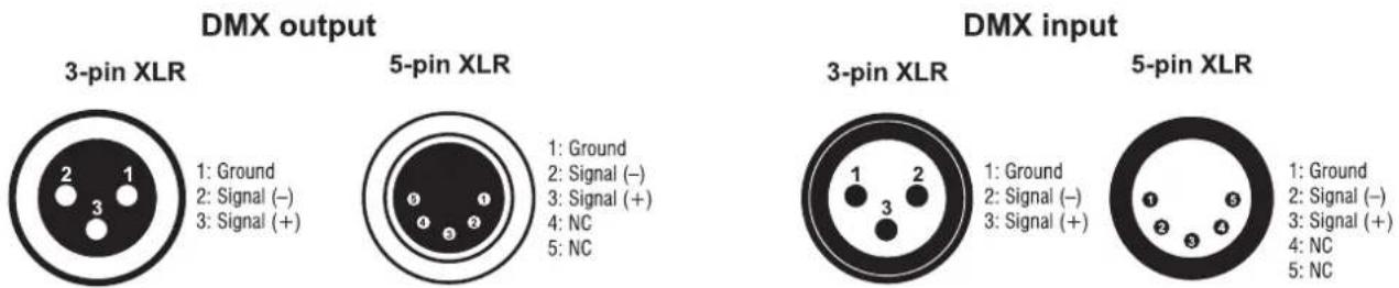
1: Ground
2: Signal (−)
3: Signal (+)
4: NC
5: NC
1: Ground
2: Signal (−)
3: Signal (+)
1: Ground
2: Signal (−)
3: Signal (+)
4: NC
5: NC

- INHALT
- CONTENTS
- INTRODUCTION
- EXPERIENCE EUROLITE
- PRODUCT FEATURES
- WHAT IS INCLUDED
- IMPORTANT SAFETY INSTRUCTIONS
- CAUTION
- OPERATING CONDITIONS
- DANGER
- ELECTRIC SHOCK CAUSED BY SHORT-CIRCUIT
- INTENDED USE
- DANGER DUE TO ELECTRICITY
- DANGER TO CHILDREN AND PEOPLE WITH RESTRICTED ABILITIES
- WARNING – RISK OF BURNS AND FIRE
- CAUTION – MATERIAL DAMAGE
- PROTECTING THE ENVIRONMENT
- DISPOSAL OF OLD EQUIPMENT
- SETUP
- INSTALLATION
- DMX512 CONNECTION
- CONNECTION TO THE POWER SUPPLY
- LED INDICATORS
- SELECT RDM FILTER MODE
- CLEANING AND MAINTENANCE
- REPLACING THE FUSE
Brand : Eurolite
Model : DMX Power Splitter 4x4
Category : Professional lighting equipment