M Series 1400 - Ice Maker Manitowoc - Free user manual and instructions
Find the device manual for free M Series 1400 Manitowoc in PDF.

| Product Type | Ice Machine |
| Brand | Manitowoc |
| Model | M Series 1400 |
| Daily Ice Production | 1400 lb (635 kg) |
| Ice Type | Full cube (crescent shape) |
| Dimensions (W x D x H) | 22 x 30 x 38 in (56 x 76 x 97 cm) |
| Net Weight | 200 lb (91 kg) |
| Electrical Supply | 115 V, 60 Hz, 15 A |
| Refrigerant | R-404A |
| Cooling Type | Air-cooled (water-cooled optional) |
| Material | Stainless steel exterior, polyethylene bin |
| Control System | Microprocessor with self-diagnostics |
| Harvest Cycle | Automatic |
| Storage Capacity | 700 lb (318 kg) |
| Cleaning Cycle | Automatic cleaning cycle |
| Water Filtration | Optional external filter |
| Warranty | 3 years parts and labor |
| Certifications | NSF, UL, CE |
Frequently Asked Questions - M Series 1400 Manitowoc
User questions about M Series 1400 Manitowoc
0 question about this device. Answer the ones you know or ask your own.
Ask a new question about this device
Download the instructions for your Ice Maker in PDF format for free! Find your manual M Series 1400 - Manitowoc and take your electronic device back in hand. On this page are published all the documents necessary for the use of your device. M Series 1400 by Manitowoc.
USER MANUAL M Series 1400 Manitowoc
Manitowoc Ice Machines MT Series
Installation, Operation and Maintenance Manual
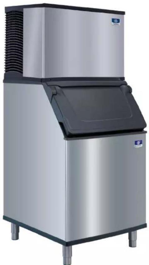
natural_image
Exterior view of a modern stainless steel ice cream maker with cooling unit (no visible text or symbols)Caution
Read this instruction before operating this equipment.
Safety Notices
Safety Notices
Read these precautions to prevent personal injury:
- Read this manual thoroughly before operating, installing or performing maintenance on the equipment. Failure to follow instructions in this manual can cause property damage, injury or death.
- Routine adjustments and maintenance procedures outlined in this manual are not covered by the warranty.
- Proper installation, care and maintenance are essential for maximum performance and trouble-free operation of your equipment. Visit our website www.manitowocice.com for manual updates, translations, or contact information for service agents in your area.
- This equipment contains high voltage electricity and refrigerant charge. Installation and repairs are to be performed by properly trained technicians aware of the dangers of dealing with high voltage electricity and refrigerant under pressure. The technician must also be certified in proper refrigerant handling and servicing procedures. All lockout and tag out procedures must be followed when working on this equipment.
- This equipment is intended for indoor use only. Do not install or operate this equipment in outdoor areas.
DEFINITIONS
DANGER
Indicates a hazardous situation that, if not avoided, will result in death or serious injury. This applies to the most extreme situations.
▲Warning
Indicates a hazardous situation that, if not avoided, could result in death or serious injury.
Caution
Indicates a hazardous situation that, if not avoided, could result in minor or moderate injury.
Notice
Indicates information considered important, but not hazard-related (e.g. messages relating to property damage).
NOTE: Indicates useful, extra information about the procedure you are performing.
▲Warning
Follow these precautions to prevent personal injury during installation of this equipment:
- Installation must comply with all applicable equipment fire and health codes with the authority having jurisdiction.
- To avoid instability the installation area must be capable of supporting the combined weight of the equipment and product. Additionally the equipment must be level side to side and front to back.
- Ice machines require a deflector when installed on an ice storage bin. Prior to using a non-OEM ice storage system with this ice machine, contact the bin manufacturer to assure their ice deflector is compatible.
- Remove all removable panels before lifting and installing and use appropriate safety equipment during installation and servicing. Two or more people are required to lift or move this appliance to prevent tipping and/or injury.
- Do not damage the refrigeration circuit when installing, maintaining or servicing the unit.
- Connect to a potable water supply only.
-
This equipment contains refrigerant charge. Installation of the line sets must be performed by a properly trained and EPA certified refrigeration technician aware of the dangers of dealing with refrigerant charged equipment.
-
Legs or casters must be installed and the legs/casters must be screwed in completely. When casters are installed the mass of this unit will allow it to move uncontrolled on an inclined surface.
These units must be tethered/secured to comply with all applicable codes. Swivel casters must be mounted on the front and rigid casters must be mounted on the rear. Lock the front casters after installation is complete.
- These products are hermetically sealed and contain fluorinated greenhouse gas R410A.
▲Warning
Follow these electrical requirements during installation of this equipment.
- All field wiring must conform to all applicable codes of the authority having jurisdiction. It is the responsibility of the end user to provide the disconnect means to satisfy local codes. Refer to rating plate for proper voltage.
• This appliance must be grounded. - This equipment must be positioned so that the plug is accessible unless other means for disconnection from the power supply (e.g., circuit breaker or disconnect switch) is provided.
- Check all wiring connections, including factory terminals, before operation. Connections can become loose during shipment and installation.
DANGER
Do not operate equipment that has been misused, abused, neglected, damaged, or altered/modified from that of original manufactured specifications. This appliance is not intended for use by persons (including children) with reduced physical, sensory or mental capabilities, or lack of experience and knowledge, unless they have been given supervision concerning use of the appliance by a person responsible for their safety. Do not allow children to play with, clean or maintain this appliance without proper supervision.
▲ Warning
Follow these precautions to prevent personal injury while operating or maintaining this equipment:
- Read this manual thoroughly before operating, installing or performing maintenance on the equipment. Failure to follow instructions in this manual can cause property damage, injury or death.
- Crush/Pinch Hazard. Keep hands clear of moving components. Components can move without warning unless power is disconnected and all potential energy is removed.
- Moisture collecting on the floor will create a slippery surface. Clean up any water on the floor immediately to prevent a slip hazard.
- Objects placed or dropped in the bin can affect human health and safety. Locate and remove any objects immediately.
- Never use sharp objects or tools to remove ice or frost. Do not use mechanical devices or other means to accelerate the defrosting process.
- When using cleaning fluids or chemicals, rubber gloves and eye protection (and/or face shield) must be worn.
DANGER
Follow these precautions to prevent personal injury during use and maintenance of this equipment:
- It is the responsibility of the equipment owner to perform a Personal Protective Equipment Hazard Assessment to ensure adequate protection during maintenance procedures.
- Do Not Store Or Use Gasoline Or Other Flammable Vapors Or Liquids In The Vicinity Of This Or Any Other Appliance. Never use flammable oil soaked cloths or combustible cleaning solutions for cleaning.
- All covers and access panels must be in place and properly secured when operating this equipment.
- Risk of fire/shock. All minimum clearances must be maintained. Do not obstruct vents or openings.
- Failure to disconnect power at the main power supply disconnect could result in serious injury or death. The power switch DOES NOT disconnect all incoming power.
- All utility connections and fixtures must be maintained in accordance with the authority having jurisdiction.
-
Turn off and lockout all utilities (gas, electric, water) according to approved practices during maintenance or servicing.
-
Units with two power cords must be plugged into individual branch circuits. During movement, cleaning or repair it is necessary to unplug both power cords.
- Never use a high-pressure water jet for cleaning on the interior or exterior of this unit. Do not use power cleaning equipment, steel wool, scrapers or wire brushes on stainless steel or painted surfaces.
- Two or more people are required to move this equipment to prevent tipping.
- Locking the front casters after moving is the owner's and operator's responsibility. When casters are installed, the mass of this unit will allow it to move uncontrolled on an inclined surface. These units must be tethered/secured to comply with all applicable codes.
- The on-site supervisor is responsible for ensuring that operators are made aware of the inherent dangers of operating this equipment.
- Do not operate any appliance with a damaged cord or plug. All repairs must be performed by a qualified service company.
Table of Contents
Safety Notices
Safety Notices ....3
Definitions 3
Section 1
General Information
Model Numbers ......9
Ice Deflector....9
Bin Installation 9
Air Baffle....9
Warranty Information......9
Model Nomenclature....10
How To Read A Model Number......10
Section 2
Installation
Location of Ice Machine....11
Clearance Requirements....11
Ice Machine Heat of Rejection 12
Removing Drain Plug and Leveling the Ice Storage Bin .....12
Air Baffle ....13
Electrical Service....13
Ground Fault Circuit Interrupter 14
Minimum Power Cord Specifications....14
Maximum Breaker Size & Minimum Circuit Amperage Chart....15
Water Supply and Drain Connections......16
Water Supply Requirements 17
Water Inlet Lines....17
Drain Connections 17
Auxiliary Base Drain Installation 17
Water Supply and Drain Line Sizing/Connections 18
Water-Cooled Condenser Water Pressure 18
Installation NotE(Australia)....18
Installation Check List....19
Before Starting the Ice Machine 19
Minimum/Maximum Slab Weight 19
Section 3
Operation
Ice Making Sequence of Operation ....21
Control Board Timers....21
Table of Contents (continued)
Safety Limits....22
Operational Checks....22
General 22
Minimum/Maximum Slab Weights....23
Ice Thickness Check 23
Section 4 Maintenance
De-scaling and Sanitizing 25
General 25
De-scaling/Sanitizing Procedure 25
Remedial Maintenance Cleaning Procedure....25
Exterior Cleaning....26
De-scaling/Sanitizing Procedure 26
Sanitizing Procedure 28
Parts Removal for De-scaling/Sanitizing....29
Remedial Maintenance De-scaling Procedure ....30
Door Removal....30
Cleaning the Condenser Filter 31
Cleaning the Condenser....31
Removal from Service/Winterization 31
Water-Cooled Ice Machines....32
Section 5 Troubleshooting
Checklist....33
Safety Limit Feature....35
Section 1
General Information
Model Numbers
This manual covers the following models:
| Self-Contained Air-Cooled | Self-Contained Water-Cooled | Remote |
| MDT0420A | MDT0420W | ---- |
| MYT0420A | MYT0420W | ---- |
| MDT0500A | MDT0500W | ---- |
| MYT0500A | MYT0500W | ---- |
| MDT0700A | MDT0700W | ---- |
| MYT0700A | MYT0700W | ---- |
| MDT1000A | MDT1000W | ---- |
| MYT1000A | MYT1000W | ---- |
| MDT1400A | MDT1400W | ---- |
| MYT1400A | MYT1400W | ---- |
| MDT1500A | MDT1500W | ---- |
| MYT1500A | MYT1500W | ---- |
Ice Deflector
An ice deflector is required when the ice machine is installed on a bin. An ice deflector is not required when the ice machine is installed on a dispenser.
Bin Installation
- All ice machines installed on a bin require an ice deflector.
- Koolaire bins have a deflector installed and require no modifications when used with a forward facing evaporator.
- Align sides and back of ice machine with sides and back of bin, when placing ice machine on bin.
Air Baffle
Self-Contained Air-Cooled Only
The air-cooled baffle prevents condenser air from recirculating.
Top Air Discharge Kit
The top air discharge kit can be used on select ice machine models. This kit directs warm exhaust air upward rather than out the side panels.
Warranty Information
Visit www.manitowocicechina.com for:
- Warranty Verification
- Warranty Registration
• View and download a copy of your warranty
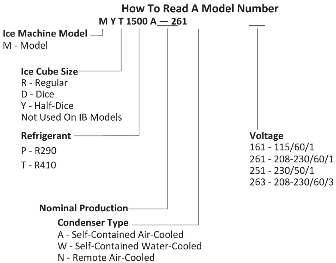
MODEL NOMENCLATURE
tree
How To Read A Model Number | Category | Description | | :--- | :--- | | M Y T 1500 A — 261 | Ice Machine Model — M - Model | | | Ice Cube Size — R - Regular D - Dice Y - Half-Dice Not Used On IB Models | | | Refrigerant — P - R290 T - R410 | | | Nominal Production — Condenser Type — A - Self-Contained Air-Cooled W - Self-Contained Water-Cooled N - Remote Air-Cooled | | Voltage | Voltage range: 161 - 115/60/1, 261 - 208-230/60/1, 251 - 230/50/1, 263 - 208-230/60/3 |NOTE: These products are hermetically sealed and contain fluorinated greenhouse gas R410A.
Section 2 Installation
Location of Ice Machine
The location selected for the ice machine must meet the following criteria. If any of these criteria are not met, select another location.
- The location must be free of airborne and other contaminants.
- The air temperature must be at least 35^ F ( 1.6^ C), but must not exceed 110^ F ( 43.4^ C).
- Remote air-cooled - The air temperature must be at least -20^ (-29°C), but must not exceed 120^ (49°C).
- The location must not be near heat-generating (ovens, dishwashers, etc.) equipment or in direct sunlight and must be protected from weather.
- The location must not obstruct airflow through or around the ice machine. Refer to the clearance requirements chart.
These ice machines are intended for use in applications such as:
- Staff kitchen areas in shops, offices and other work environments
- Clients in hotels, motels, farmhouses, bed and breakfast and other residential type environments
- Catering and similar non-retail applications
▲Warning
Two or more people or a lifting device are required to lift this appliance.
Clearance Requirements
| ▲WarningDo not obstruct ice machine vents or openings. |
| MT0420MT0500/MT0700MT1000/MT1400/MT1500 | Self-Contained Air-Cooled | Water-Cooled and Remote* |
| Top/Sides 8" (20.3 cm) 8" (20.3 cm) | ||
| Back 5" (12.7 cm) 5" (12.7 cm) | ||
| MT0420 Tropical Rating 50 Hz Only | Self-Contained Air-Cooled | Water-Cooled |
| Top 24" (61.0 cm) 8" (20.3 cm) | ||
| Sides 12" (30.5 cm) 8" (20.3 cm) | ||
| Back 5" (12.7 cm) 5" (12.7 cm) | ||
| MT1000 Tropical Rating 50 Hz Only | Self-Contained Air-Cooled | Water-Cooled and Remote |
| Top 12" (30.5 cm) 8" (20.3 cm) | ||
| Sides 8" (20.3 cm) 8" (20.3 cm) | ||
| Back 5" (12.7 cm) 5" (12.7 cm) | ||
Notice
The ice machine must be protected if it will be subjected to temperatures below 32^ F ( 0^ C). Failure caused by exposure to freezing temperatures is not covered by the warranty.
Ice Machine Heat of Rejection
| Series Ice Machine | Heat of Rejection1 | |
| Air Conditioning2 | Peak | |
| MT0420 54 | 00 6300 | |
| MT0500 53 | 00 6100 | |
| MT0700 12 | 400 13700 | |
| MT1000 60hz | 15400 17100 | |
| MT1000 50hz | 14600 16200 | |
| MT1400 24 | 700 29000 | |
| MT1500 24 | 700 29000 | |
1 B.T.U./Hour
2 Because the heat of rejection varies during the ice making cycle, the figure shown is an average.
Ice machines, like other refrigeration equipment, reject heat through the condenser. It is helpful to know the amount of heat rejected by the ice machine when sizing air conditioning equipment where self-contained air-cooled ice machines are installed.
This information is also necessary when evaluating the benefits of using water-cooled or remote condensers to reduce air conditioning loads. The amount of heat added to an air conditioned environment by an ice machine using a water-cooled or remote condenser is negligible.
Knowing the amount of heat rejected is also important when sizing a cooling tower for a water-cooled condenser. Use the peak figure for sizing the cooling tower.
Removing Drain Plug and Leveling the Ice Storage Bin
▲Warning
To avoid instability, the bin/dispenser must be installed in an area capable of supporting the weight of the bin/dispenser, ice machine and a full bin of ice (48" models 1000 lbs [454 kg], 30" models 750 lbs [340 kg]). The bin/dispenser must be level side-to-side and front-to-back before installing the ice machine.
- Remove threaded plug from drain fitting.
- Screw the leveling legs onto the bottom of the bin.
- Screw the foot of each leg in as far as possible.
Notice
The legs must be screwed in tightly to prevent them from bending.
- Move the bin into its final position.
- Level the bin to assure that the bin door closes and seals and the ice machine operates properly. Use a level on top of the bin. Turn the base of each foot as necessary to level the bin.
- Inspect bin gasket prior to ice machine installation. (Our bins come with a closed cell foam gasket installed along the top surface of the bin.)
- Remove all panels from ice machine before lifting and installing on bin. Remove front panel, top cover, left and right side panels.
Air Baffle
Self-Contained Air-Cooled Only
To install:
- Loosen the back panel screws next to the condenser.
- Align the keyhole slots in the air baffle with the screw holes and slide the baffle down to lock in place.
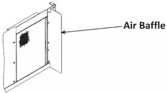
text_image
Air Baffle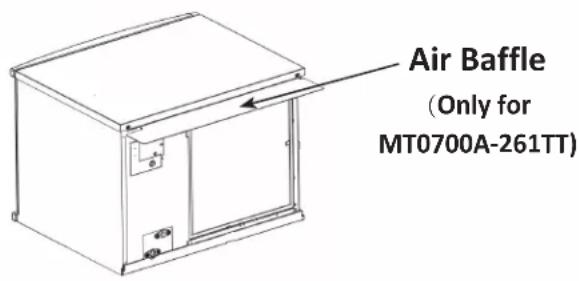
text_image
Air Baffle (Only for MT0700A-261TT)Air Gap
A greater than 1-inch air gap is built into the ice machine for back-flow prevention. This air gap exceeds NSF 12 requirements for back-flow prevention.
natural_image
Line drawing of a cabinet or enclosure with a grid-patterned panel and an arrow indicating direction (no text or symbols)This air gap is greater than 1"
Electrical Service
▲Warning
All electrical work, including wire routing and grounding must conform to all applicable national and local electrical codes.
Minimum Circuit Ampacity
The minimum circuit ampacity is used to help select the wire size of the electrical supply. (Minimum circuit ampacity is not the ice machine's running amp load.)
Electrical Requirements
Refer to Ice Machine Model/Serial Plate for voltage/amperage specifications.
- A separate fuse/circuit breaker must be provided for each ice machine.
- The wire size (or gauge) is dependent upon location, materials used, length of run, etc., so it must be determined by a qualified electrician.
- The ice machine must be grounded. Check all green ground screws in the control box and verify they are tight before starting the ice machine.
- The maximum allowable voltage variation is ± 10% of the rated voltage at ice machine start-up (when the electrical load is highest).
Notice
Observe correct polarity of incoming line voltage. Incorrect polarity can lead to erratic ice machine operation. Operate equipment only on the type of electricity indicated on the specification plate.
GROUND FAULT CIRCUIT INTERRUPTER
Ground Fault Circuit Interrupter (GFCI/GFI) protection is a system that shuts down the electric circuit (opens it) when it senses an unexpected loss of power, presumably to ground. GFCI/GFI circuit protection is not recommended with our equipment. If code requires the use of a GFCI/GFI, then you must follow the local code. The circuit must be dedicated, sized properly and there must be a panel GFCI/GFI breaker. We do not recommend GFCI/GFI outlets as they are known for more intermittent nuisance trips than panel breakers.
MINIMUM POWER CORD SPECIFICATIONS
If a power cord is used, the wire size to the receptacle is dependent upon location, materials used, length of run, etc., so it must be determined by a qualified electrician. Local, state or national requirements will supersede our minimum requirements.
For United Kingdom Only
As the colors of the wires in the mains lead of the appliance may not correspond with the colored markings identifying the terminals in your plug, proceed as follows:
- The wire which is colored green and yellow must be connected to the terminal in the plug which is marked with the letter E or by the earth ground symbol or colored green or green and yellow.
- The wire colored blue must be connected to the terminal which is marked with the letter N or colored black.
- The wire colored brown must be connected to the terminal which is marked with the letter L or colored red.
Maximum Breaker Size & Minimum
Circuit Amperage Chart
Important
Due to continuous improvements, this information is for reference only. Please refer to the ice machine serial number tag to verify electrical data. Serial tag information overrides information listed on this page.
| Ice Machine | Voltage/Phase/Cycle | Air-Cooled Water | -Cooled Remote | ||||
| Maximum Fuse/Circuit Breaker | Minimum Circuit Amps | Maximum Fuse/Circuit Breaker | Minimum Circuit Amps | Maximum Fuse/Circuit Breaker | Minimum Circuit Amps | ||
| MT0420 | 115/1/60 1 | 5 11.3 15 1 | 0.6 N/A N/A | ||||
| 230/1/50 1 | 5 6.2 15 5.8 | N/A N/A | |||||
| 230/1/60 1 | 5 6.2 15 5.8 | N/A N/A | |||||
| MT0500 | 115/1/60 2 | 20 12.7 20 1 | 2.0 N/A N/A | ||||
| 230/1/50 1 | 5 6.3 15 5.9 | N/A N/A | |||||
| MT0700 | 208-230/1/60 | 15 8.5 | 15 8.2 N/A N/A | ||||
| 230/1/50 1 | 5 8.6 20 8.2 | N/A N/A | |||||
| MT1000 | 208-230/1/60 | 15 10.8 | 15 10.1 N/A N/A | ||||
| 230/1/50 1 | 5 11.3 N/A | N/A N/A N/A | |||||
| MT1400 | 230/1/50 30 | 17.1 30 14.2 | N/A N/A | ||||
| MT1500 | 208-230/1/60 | 30 18.2 | 30 16.8 N/A N/A | ||||
Water Supply and Drain Connections
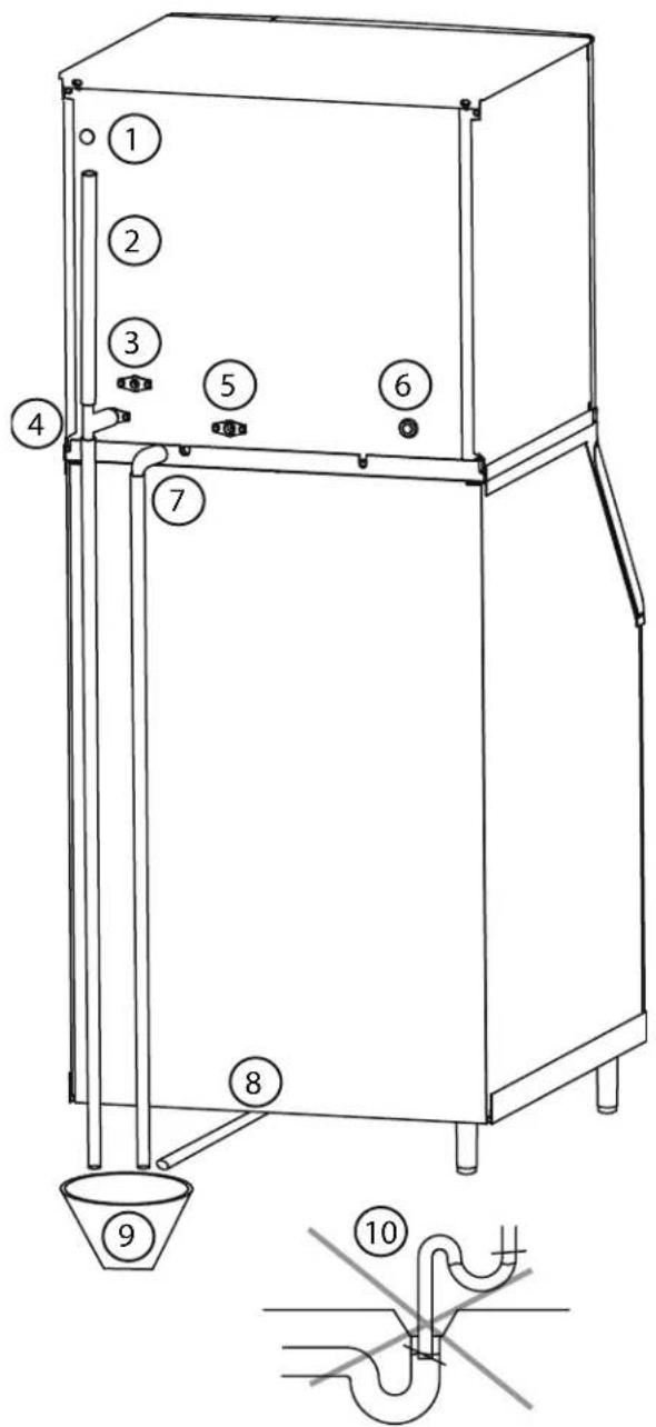
text_image
Technical diagram of a mechanical device with numbered components and a piping connection diagram below.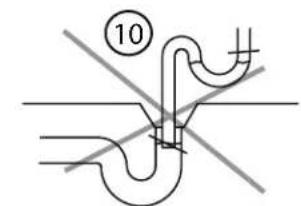
text_image
10Caution
Do not apply heat to water inlet valve or water drain fittings. Heating will damage the nonmetallic connector. Do not over tighten fittings. Two truns after hand tight is the maximum.
| Item Description | |
| 1 Electrical Entrance | |
| 2 Vent Tube-Minimum Height18"(46cm) | |
| 3 Potable Water Inlet-3/8"FPT | |
| 4 Potable Water Drain_1/2"FPT | |
| 5 Condenser Water Outlet-1/2"FPT Water-cooled Models Only | |
| 6 Condenser Water Inlet See"Condenser Water Inlet" on page 18 for fitting sizes | |
| 7 Base Drain-1/2" CPVC Socket | |
| 8 Bin Drain - See "Bin Drain" on page 18 for fitting sizes | |
| 9 Floor Drain- Open and Trapped | |
| 10 | Do Not Trap Drain Line - Leave Air Gap Between Drain Line and Floor Drain |
Water Supply Requirements
Local water conditions may require treatment of the water to inhibit scale formation, filter sediment, and remove chlorine odor and taste.
▲Warning
Connect to a potable water supply only. Plumbing must conform to state, local and national codes.
WATER INLET LINES
Follow these guidelines to install water inlet lines:
- If you are installing a water filter system, refer to the installation instructions supplied with the filter system for ice making water inlet connections.
- Do not connect the ice machine to a hot water supply. Be sure all hot water restrictors installed for other equipment are working. (Check valves on sink faucets, dishwashers, etc.)
- If water pressure exceeds the maximum recommended pressure of 80 psi (552 kPa), obtain a water pressure regulator from your local distributor.
• Install a water shut-off valve for both the ice making and condenser water lines. - Insulate water inlet lines to prevent condensation.
DRAIN CONNECTIONS
Follow these guidelines when installing drain lines to prevent drain water from flowing back into the ice machine and storage bin:
- Drain lines must have a 1.5 inch drop per 5 feet of run (2.5 cm per meter), and must not create traps.
- The floor drain must be large enough to accommodate drainage from all drains.
- Run separate bin and ice machine drain lines. Insulate them to prevent condensation.
- Vent the bin and ice machine drain to the atmosphere. Do not vent the condenser drain on water-cooled models.
AUXILIARY BASE DRAIN INSTALLATION
An auxiliary drain is located in the ice machine base to remove moisture in high humidity areas.
- View the back of the ice machine base on the compressor side and locate and remove the cap plug.
- Route tubing to an open site drain:
- Use 1/2 inch CPVC tubing.
- Apply a bead of silicone around the exterior of the ice machine tubing and insert into ice machine base. The silicone will secure the tubing and provide a watertight seal.
- Provide support for tubing.
Water Supply and Drain Line Sizing/Connections
| Location | Water Temperature | Water Pressure | Ice Machine Fitting | Tubing Size Up to Ice Machine Fitting |
| Ice Making Water Inlet | 35°F (2°C) Min.90°F (32°C) Max. | 20 psi (140 kPa) Min.80 psi (552 kPa) Max. | 3/8" (.95 cm) Female Pipe Thread | 3/8" (.95 cm) min. inside diameter |
| Ice Making Water Drain | - | - | 1/2" (1.27 cm) Female Pipe Thread | 1/2" (1.27 cm) min. inside diameter |
| Condenser Water Inlet | 90°F (32°C) Max. | Standard20 psi (140 kPa) Min.275 psi (1896 kPa) Max.High Pressure Option20 psi (140 kPa) Min.350 psi (2410 kPa) Max. | 3/8" Female Pipe Thread | |
| Condenser Water Drain | - | - | 1/2" (1.27 cm) Female Pipe Thread | 1/2" (1.27 cm) min. inside diameter |
| Bin Drain - | - | 3/4" (1.91 cm) Female Pipe Thread | 3/4" (1.91 cm) min. inside diameter | |
| Large Capacity Bin Drain | - | - | 1" (2.54 cm) Male Pipe Thread | 1" (2.54 cm) min. inside diameter |
WATER-COOLED CONDENSER WATER PRESSURE
Water pressure at the condenser cannot exceed 150 psig (1034 kPa) with the standard water-regulating valve. Contact your distributor if your water pressure is greater than 150 psig (1034 kPa). A special order condenser/water-regulating valve is available that allows water pressure up to 275 psig (1897 kPa).
Important
The Commonwealth of Massachusetts requires that all water-cooled models must be connected only to a closed loop, cooling tower system.
INSTALLATION NOTE(AUSTRALIA)
This appliance incorporate a registered air gap as a back flow prevention device.
Please also refer to the installation in accordance with standard AS/NZS 3500.1 and AS/NZS 3500.2.
Installation Check List
□ Is the Ice Machine level?
□ Have all of the electrical and water connections been made?
□ Has the supply voltage been tested and checked against the rating on the nameplate?
☐ Is there proper clearance around the ice machine for air circulation?
☐ Is the ice machine grounded and polarity correct?
☐ Has the ice machine been installed where ambient temperatures will remain in the range of 35^ - 110^ F ( 1.6^ - 43.3^ C)?
☐ Has the ice machine been installed where the incoming water temperature will remain in the range of 35^ - 90^ F ( 1.6^ - 32.2^ C)?
☐ Is there a separate drain for the potable water, bin and water-cooled condenser?
□ Are the ice machine and bin drains vented?
☐ Are all refrigerant lines free from contact with other components?
☐ Are all electrical leads free from contact with refrigeration lines and moving equipment?
☐ Has the owner/operator been instructed regarding maintenance and the use of our De-scaler and Sanitizer?
☐ Has the owner/operator completed the warranty registration card?
☐ Has the ice machine and bin been sanitized?
☐ Is the ice thickness set correctly? (Refer to Operational Checks to check/set the correct ice bridge thickness).
BEFORE STARTING THE ICE MACHINE
All ice machines are factory-operated and adjusted before shipment. Normally, new installations do not require any adjustment. Starting the ice machine and completing the Operational Checks are the responsibilities of the owner/operator.
Step 1 Refer to “De-scaling/Sanitizing Procedure” on page 26 and sanitize the ice machine and bin before placing in operation.
Step 2 Refer to "Ice Making Sequence of Operation" on page 21 for operational details.
MINIMUM/MAXIMUM SLAB WEIGHT
Adjust ice thickness to maintain the correct bridge thickness and “Minimum/Maximum Slab Weights” on page 23.
▲Warning
Potential Personal Injury Situation
Do not operate equipment that has been misused, abused, neglected, damaged, or altered/modified from that of original manufactured specifications.
THIS PAGE INTENTIONALLY LEFT BLANK
Section 3 Operation
Ice Making Sequence of Operation
NOTE: The toggle switch must be in the ICE position and the water curtain must be closed before the ice machine will start.
Water Purge Cycle
The ice machine purges any remaining water from the water trough down the drain and the refrigeration compressor starts.
Freeze Cycle
Prechill - The refrigeration system chills the evaporator before water flow over the evaporator starts. The water inlet valve energizes during the pre-chill and remains on until the Ice Thickness Float Switch is satisfied.
Freeze - Water flowing across the evaporator freezes and builds ice on the evaporator. After a sheet of ice has formed, the Harvest Float Switch signals the control board to start a harvest cycle.
Harvest Cycle
Any remaining water is purged down the drain as refrigerant gas warms the evaporator. When the evaporator warms, the sheet of cubes slides off the evaporator and into the storage bin. If all cubes fall clear of the water curtain, the ice machine starts another freeze cycle.
Full Bin Cycle
If the water curtain is held open by ice cubes, the ice machine shuts off and starts a 3-minute delay period. When the water curtain closes, the ice machine starts a new cycle at the water purge, provided the 3-minute delay period has expired.
CONTROL BOARD TIMERS
The control board has the following non-adjustable timers:
- The ice machine is locked into the freeze cycle for 6 minutes before a harvest cycle can be initiated.
- The maximum freeze time is 60 minutes, at which time the control board automatically initiates a harvest sequence.
- The maximum harvest time is 3.5 minutes. The control board automatically initiates a freeze sequence when these times are exceeded.
SAFETY LIMITS
Safety limits are stored and indicated by the control board. The number of cycles required to stop the ice machine varies for each safety limit.
Safety limits can be reset by pressing the On/Off button and starting a new ice making cycle.
A safety limit is indicated by a flashing Service Light on the control board.
- Safety Limit 1 - If the freeze time reaches 60 minutes, the control board automatically initiates a harvest cycle. If 6 consecutive 60-minute freeze cycles occur, the ice machine stops.
- Safety Limit 2 - If three consecutive 3.5 minute harvest cycles occur the SL#2 light on the control board will flash on/off at 1 second intervals. After 75 consecutive 3.5 minutes harvest cycles the SL#2 light will be energized continuously. If 100 consecutive 3.5 minute harvest cycles occur, the ice machine stops and the SL#2 light on the control board will be on continuously.
- Water Loss - If the water trough doesn't fill within 4 minutes of the water inlet valve energizing, the ice machine will stop for 30 minutes then restart. If 100 consecutive failures occur the ice machine locks out and the SL#1 & SL#2 lights flash on/off at 1 second intervals.
Operational Checks
GENERAL
All ice machines are factory-operated and adjusted before shipment. Normally, new installations do not require any adjustment.
To ensure proper operation, always follow the Operational Checks:
- when starting the ice machine for the first time
• after a prolonged out-of-service period
• after de-scaling and sanitizing
NOTE: Routine adjustments and maintenance procedures are not covered by the warranty.
MINIMUM/MAXIMUM SLAB WEIGHTS
Adjust ice thickness to meet chart specifications.
| Model | Minimum Ice Weight Per Cycle | Maximum Ice Weight Per Cycle |
| MT0420 | 3.4 lbs1542 g | 3.9 lbs1769 g |
| MT0500 | 4.125 lbs1871 g | 4.75 lbs2154 g |
| MT0700 | 4.125 lbs1871 g | 4.75 lbs2154 g |
| MT1000 | 7.25 lbs3288 g | 7.75 lbs3515 g |
| MT1400 | 13.2 lbs5987 g | 14.8 lbs6713 g |
| MT1500 | 13.2 lbs5987 g | 14.8 lbs6713 g |
ICE THICKNESS CHECK
After a harvest cycle, inspect the ice cubes in the ice storage bin. The ice thickness float switch is factory-set to maintain the ice bridge thickness at 1/8" (3 mm).
NOTE: Make sure the water curtain is in place when performing this check. It prevents water from splashing out of the water trough.
-
Inspect the bridge connecting the cubes. It should be about 1/8" (3 mm) thick.
-
If adjustment is necessary make the following adjustment as you face the machine.
NOTE: The float can be adjusted with a 3/4" wrench while the water trough is in place.
- Turn the ice thickness float switch to the right to increase bridge thickness
- Turn the ice thickness float switch to the left to decrease bridge thickness.
- Test run two cycles to verify bridge thickness.
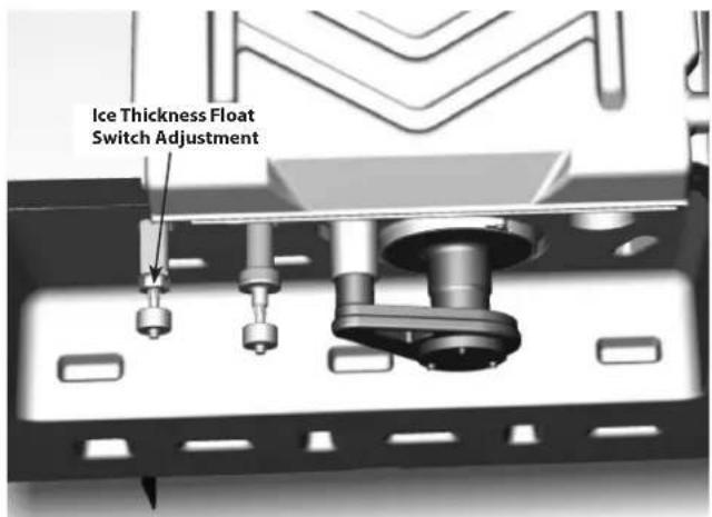
text_image
Ice Thickness Float Switch AdjustmentTHIS PAGE INTENTIONALLY LEFT BLANK
De-scaling and Sanitizing
GENERAL
You are responsible for maintaining the ice machine in accordance with the instructions in this manual. Maintenance procedures are not covered by the warranty.
De-scale and sanitize the ice machine every six months for efficient operation. If the ice machine requires more frequent de-scaling, consult a qualified service company to test the water quality and recommend appropriate water treatment. An extremely dirty ice machine must be taken apart for de-scaling and sanitizing. Sanitizing for Exerior, Remedial, and Detailed procedures can be performed independently and more frequently than de-scaling if desired.
Manitowoc Ice Machine De-scaler and Sanitizer are the only products approved for use in this ice machine.
Caution
Use only approved Ice Machine Descaler and Sanitizer for this application (Manitowoc De-scaler part number 9405463 and Manitowoc Sanitizer part number 9405653). It is a violation of Federal law to use these solutions in a manner inconsistent with their labeling. Read and understand all labels printed on bottles before use.
Caution
Do not mix De-scaler and Sanitizer solutions together. It is a violation of Federal law to use these solutions in a manner inconsistent with their labeling.
▲Warning
Wear rubber gloves and safety goggles (and/or face shield) when handling Ice Machine De-scaler or Sanitizer.
DE-SCALING/SANITIZING PROCEDURE
This procedure must be performed a minimum of once every six months.
- The ice machine and bin must be disassembled, de-scaled and sanitized.
- All ice produced during the de-scaling and sanitizing procedures must be discarded.
- Removes mineral deposits from areas or surfaces that are in direct contact with water.
REMEDIAL MAINTENANCE CLEANING PROCEDURE
- This procedure cleans all components in the water flow path, and is used to clean the ice machine between the bi-yearly de-scaling/sanitizing procedure without removing the ice from the bin/dispenser.
- This technology will also allow initiation and completion of a de-scale or sanitize cycle, after which the ice machine automatically starts ice making again.
EXTERIOR CLEANING
Clean the area around the ice machine as often as necessary to maintain cleanliness and efficient operation.
Wipe surfaces with a damp cloth rinsed in water to remove dust and dirt from the outside of the ice machine. If a greasy residue persists, use a damp cloth rinsed in a mild dish soap and water solution. Wipe dry with a clean, soft cloth.
The exterior panels have a clear coating that is stain resistant and easy to clean. Products containing abrasives will damage the coating and scratch the panels.
- Never use steel wool or abrasive pads for cleaning.
- Never use chlorinated, citrus-based or abrasive cleaners on exterior panels and plastic trim pieces.
Detailed De-scaling/Sanitizing Procedure
Caution
Use only approved Ice Machine Descaler and Sanitizer for this application (Manitowoc De-scaler part number 9405463 and Manitowoc Sanitizer part number 9405653). It is a violation of Federal law to use these solutions in a manner inconsistent with their labeling. Read and understand all labels printed on bottles before use.
Caution
Do not mix De-scaler and Sanitizer solutions together. It is a violation of Federal law to use these solutions in a manner inconsistent with their labeling.
▲Warning
Wear rubber gloves and safety goggles (and/or face shield) when handling Ice Machine De-scaler or Sanitizer.
Ice machine de-scaler is used to remove lime scale and mineral deposits. Ice machine sanitizer disinfects and removes algae and slime.
Step 1 Remove the front door to access the evaporator compartment. Ice must not be on the evaporator during the de-scale/sanitize cycle. Set the toggle switch to the OFF position after ice falls from the evaporator at the end of a harvest cycle. Or, set the switch to OFF and allow the ice to melt off the evaporator(s).
| Notice |
| Never use anything to force ice from the evaporator. Damage may result. |
Step 2 Remove all ice from the bin/ dispenser.
Step 3 Place the toggle switch in the CLEAN position. Water will flow through the water dump valve and down the drain. Wait until the water trough refills, then add the proper amount of ice machine descaler.
| Model Amount of De-scaler | |
| MT0420 MT0500MT0700 MT1000 | 5 ounces (150 ml) |
| MT1400 MT1500 9 | ounces (265 ml) |
Step 4 Wait until the clean cycle is complete (approximately 30 minutes). Then disconnect power to the ice machine (and dispenser when used).
| ▲Warning |
| Disconnect the electric power to the ice machine at the electric service switch box. |
Step 5 Remove parts for de-scaling.
Please refer to parts removal and continue with step 6 when the parts have been removed - Refer to page 29.
Step 6 Mix a solution of de-scaler and lukewarm water. Depending upon the amount of mineral buildup, a larger quantity of solution may be required. Use the ratio in the table below to mix enough solution to thoroughly clean all parts.
| Solution Type | Water Mixed with | |
| De-scaler 1 | gal. (4 L) | 16 oz (500 ml) de-scaler |
Step 7 Use 1/2 of the de-scaler/water mixture to clean all components. The de-scaler solution will foam when it contacts lime scale and mineral deposits; once the foaming stops use a soft-bristle nylon brush, sponge or cloth (NOT a wire brush) to carefully clean the parts. Soak parts for 5 minutes (15-20 minutes when heavily scaled). Rinse all components with clean water.
Step 8 While components are soaking, use 1/2 of the de-scaler/water solution to clean all foodzone surfaces of the ice machine and bin (or dispenser). Use a nylon brush or cloth to thoroughly clean the following ice machine areas:
- Evaporator plastic parts – including top, bottom and sides
- Bin bottom, sides and top
Rinse all areas thoroughly with clean water.
SANITIZING PROCEDURE
Step 9 Mix a solution of sanitizer and lukewarm water.
| Solution Type | Water Mixed with |
| Sanitizer 3 | gal. (12 L) |
| 2 oz (60 ml) sanitizer |
Step 10 Use 1/2 of the sanitizer/water solution to sanitize all removed components. Use a spray bottle to liberally apply the solution to all surfaces of the removed parts or soak the removed parts in the sanitizer/water solution. Do not rinse parts after sanitizing.
Step 11 Use 1/2 of the sanitizer/water solution to sanitize all foodzone surfaces of the ice machine and bin (or dispenser). Use a spray bottle to liberally apply the solution. When sanitizing, pay particular attention to the following areas:
- Evaporator plastic parts - including top, bottom and sides
- Ice machine base (top of bin) and area above the water trough
- Bin sides and bottom
Do not rinse the sanitized areas.
Step 12 Replace all removed components.
Step 13 Wait 20 minutes.
Step 14 Reapply power to the ice machine and place the toggle switch in the CLEAN position.
Step 15 Wait until the water trough refills, then add the proper amount of Manitowoc Ice Machine Sanitizer to the water trough.
| Model Amount of Sanitizer | |
| MT0420 MT0500MT0700 MT1000 | 3 ounces (90 ml) |
| MT1400 MT1500 6 | ounces (180 ml) |
Step 16 After the sanitize cycle is complete (approximately 24 minutes) move the toggle switch to the ICE position to start ice making.
Parts Removal for De-scaling/Sanitizing
Single Evaporator Ice Machines
A. Remove the water curtain
- Gently flex the curtain in the center and remove it from the right side.
- Slide the left pin out.
B. Remove the water trough
- Depress tabs on right and left side of the water trough.
- Allow front of water trough to drop as you pull forward to disengage the rear pins.
C. Remove the ice thickness and harvest float switches
- Pull the float switch straight down to disengage.
- Lower the float switch until the wiring connector is visible.
- Disconnect the wire lead from the float switch.
- Remove the float switch from the ice machine.
D. Remove the water distribution tube
NOTE: Distribution tube thumbscrews are retained to prevent loss. Loosen thumbscrews but do not pull thumbscrews out of distribution tube.
- Loosen the two outer screws (do not remove screws completely they are retained to prevent loss) and pull forward on the distribution tube to release from slip joint.
- Disassemble distribution tube by loosening the two (2) middle thumbscrews and dividing the distribution tube into two pieces.
• Proceed to page 27 Step 6.
Remedial Maintenance De-scaling Procedure
This procedure cleans all components in the water flow path, and is used to clean the ice machine between the bi-yearly descaling/sanitizing procedure.
Ice machine de-scaler is used to remove lime scale and mineral deposits. Ice machine sanitizer disinfects and removes algae and slime.
NOTE: Although not required and dependent on your installation, removing the ice machine top cover may allow easier access.
Step 1 Ice must not be on the evaporator during the de-scale/sanitize cycle. Follow one of the methods below:
- Move the toggle switch to the OFF position at the end of a harvest cycle after ice falls from the evaporator(s).
- Move the toggle switch to the OFF position and allow the ice to melt.
Notice
Never use anything to force ice from the evaporator. Damage may result.
Step 2 Open the front door and move the toggle switch to the CLEAN position. Wait until the water trough refills (approximately 1 minute) and then add the proper amount of Ice Machine De-scaler to the water trough.
| Model Amount of De-scaler | |
| MT0420 MT0500MT0700 MT1000 | 5 ounces (150 ml) |
| MT1400 MT1500 9 ounces (265 ml) | |
Step 3 After 1 minute place the toggle switch in the ICE position and close and secure the front door. The ice machine will automatically start ice making after the Clean cycle is complete (approximately 24 minutes).
Door Removal
- Use a Phillips screwdriver to loosen the two screws securing the door. Do not remove, they are retained to prevent loss.
- Tilt door forward and lift up to remove.
Cleaning the Condenser Filter
The washable filter on self-contained ice machines is designed to catch dust, dirt, lint and grease. Clean the filter with a mild soap and water.
Cleaning the Condenser
▲Warning
Disconnect electric power to the ice machine head section and the remote condensing unit at the electric service switches before cleaning the condenser.
A dirty condenser restricts airflow, resulting in excessively high operating temperatures. This reduces ice production and shortens component life.
- Clean the condenser at least every six months.
▲Warning
The condenser fins are sharp. Use care when cleaning them.
- Shine a flashlight through the condenser to check for dirt between the fins.
- Blow compressed air or rinse with water from the inside out (opposite direction of airflow).
- If dirt still remains call a service agent to clean the condenser.
Removal from Service/Winterization
- Clean and sanitize the ice machine.
- Move the toggle switch to the OFF position and turn off the ice machine.
- Turn off the water supply, disconnect and drain the incoming ice-making water line at the rear of the ice machine and drain the water trough.
- Energize the ice machine, wait one minute for the water inlet valve to open and blow compressed air in both the incoming water and the drain openings in the rear of the ice machine to remove all water.
- Move the toggle switch to the OFF position and turn off the ice machine. Disconnect the electric power at the circuit breaker or the electric service switch.
- Fill spray bottle with sanitizer/water solution and spray all interior food zone surfaces. Do not rinse and allow to air dry.
- Replace all panels.
WATER-COOLED ICE MACHINES
- Perform steps 1-6 under "Removal from Service/Winterization".
- Disconnect the incoming water and drain line from the water-cooled condenser.
- Energize the ice machine in the freeze cycle. The increasing refrigerant pressure will open the water regulating valve.
- Blow compressed air through the condenser until no water remains.
- Replace all panels.
Section 5
Troubleshooting
Checklist
If a problem arises during operation of your ice machine, follow the checklist below before calling service. Routine adjustments and maintenance procedures are not covered by the warranty.
| Problem Possible Cause To Correct | |||
| Ice machine does not operate. | No electrical power to the ice machine. | Replace the fuse/reset the breaker/turn on the main switch/plug power cord into receptacle. | |
| Ice machine needs to be turned on. | Place the toggle switch in the ICE position to start ice making. | ||
| Curtain in open position (down). | Curtain must be in the closed position and capable of swinging freely. | ||
| Ice machine stops, and can be restarted by turning the ice machine OFF and then ON. | Safety limit feature stopping the ice machine. | Refer to “Safety Limit Feature” on page 35. | |
| Ice sheet is thick Water trough | gh level is too high. Adjust ice thickness float. | ||
| Power button was turned off/ on during freeze cycle and ice remained on evaporator. | Allow ice to thaw and release from evaporator, then restart. | ||
| Ice damper was opened then closed in the harvest cycle before the ice released. | Allow ice to thaw and release from evaporator, then restart. | ||
| Ice machine does not release ice or is slow to harvest. | Ice machine is dirty. De-scale and sanitize the ice machine. | ||
| Ice machine is not level. Level the ice machine. | |||
| Low air temperature around ice machine (air-cooled models). | Air temperature must be at least 40°F (4°C). | ||
| Water regulating valve leaks in harvest mode (water-cooled models). | Replace water regulating valve. | ||
| Ice machine does not cycle into harvest mode. | The six-minute freeze time lock-in has not expired yet. | Wait for freeze lock-in to expire. | |
| Ice thickness float switch is dirty. | De-scale and sanitize the ice machine. | ||
| Ice thickness float switch wire is disconnected. | Connect the wire. | ||
| Ice thickness float switch is out of adjustment. | Adjust the ice thickness float switch. | ||
| Uneven ice fill (thin at top of evaporator). | See “Shallow or Incomplete Cubes”. | ||
| Ice quality is poor (soft or not clear). | Poor incoming water quality. | Contact a qualified service company to test the quality of the incoming water and make appropriate filter recommendations. | |
| Water filtration is poor. Replace the filter. | |||
| Ice machine is dirty. De-scale and sanitize the ice machine. | |||
| Water softener is working improperly (if applicable). | Repair the water softener. | ||
| Ice machine produces shallow or incomplete cubes, or the ice fill pattern on the evaporator is incomplete. | Ice thickness float switch is out of adjustment. | Adjust the ice thickness float switch. | |
| Water trough level is too high or too low. | Check the water level and adjust if required. | ||
| Water filtration is poor. Replace the filter. | |||
| Hot incoming water. Connect the ice machine to a cold water supply. | |||
| Incorrect incoming water pressure. | Water pressure must be 20-80 psi (137.9 - 551.5 kPa). | ||
| Ice machine is not level. Level the ice machine. | |||
| Low ice capacity. The condenser is dirty. Clean the condenser. | |||
Safety Limit Feature
In addition to the standard safety controls, such as the high pressure cutout, your ice machine features built-in safety limits which will stop the ice machine if conditions arise which could cause a major component failure.
Refer to Safety Limits Section 3 for more information on safety limits.
Before calling for service, re-start the ice machine using the following procedure:
- Move the toggle switch to OFF, then the ICE position,
A. If the safety limit feature has stopped the ice machine, it will restart after a short delay. Proceed to step 2.
B. If the ice machine does not restart, see "Ice machine does not operate" on page 33.
- Allow the ice machine to run to determine if the condition repeats.
A. If the ice machine stops again, the condition has repeated. Call for service.
B. If the ice machine continues to run, the condition has corrected itself. Allow the ice machine to continue running.