Q210 - Ice Maker Manitowoc - Free user manual and instructions
Find the device manual for free Q210 Manitowoc in PDF.


| Product Type | UnderCounter Ice Machine |
| Model | Q210 |
| Series | Q Series |
| Ice Production Rate | Not specified in manual (typical: up to 210 lbs/day) |
| Electrical Supply (Air-Cooled) | 115V/60Hz/1ph: 6.5A, 208-230V/60Hz/1ph: 3.6A, 230V/50Hz/1ph: 3.6A |
| Electrical Supply (Water-Cooled) | 115V/60Hz/1ph: 6.1A, 208-230V/60Hz/1ph: 3.1A, 230V/50Hz/1ph: 3.1A |
| Maximum Fuse/Circuit Breaker | 15A for all configurations |
| Power Cord | 8 ft (2.44 m), 115V models with NEMA 5-15P plug; 208-230V models without plug |
| Water Inlet Connection | 3/8" FPT (ice making), 3/8" FPT (condenser, water-cooled) |
| Water Drain Connection | 1/2" FPT (condenser drain, water-cooled), 1/2" FPT (bin drain) |
| Water Supply Requirements | 20-80 psi (137.9-551.5 kPa), 40-90°F (4.4-32.2°C) |
| Ambient Temperature Range | 40-110°F (4.4-43.3°C) |
| Ice Bridge Thickness | Adjustable, factory set at 1/8" (3.2 mm) |
| Ice Thickness Probe | Adjustable, senses water contact to initiate harvest |
| Safety Limit #1 | Freeze cycle >60 min for 3 consecutive cycles shuts down |
| Safety Limit #2 | Harvest cycle >3.5 min for 3 consecutive cycles shuts down |
| Compressor Type | Not specified (hermetic) |
| Condenser Type | Air-cooled or water-cooled (self-contained) |
| Refrigerant | Not specified (likely R-404A or R-134a) |
| Cleaning Frequency | Every 6 months or as needed |
| Approved Cleaner | Manitowoc Ice Machine Cleaner (94-0546-3) |
| Approved Sanitizer | Manitowoc Ice Machine Sanitizer (94-0565-3) |
| Warranty (Commercial) | 3 years parts/labor, 5 years evaporator/compressor |
| Warranty (Residential) | 12 months from sale date |
| Accessories | Bin caster, Arctic Pure water filter, cleaner/sanitizer |
Frequently Asked Questions - Q210 Manitowoc
User questions about Q210 Manitowoc
0 question about this device. Answer the ones you know or ask your own.
Ask a new question about this device
Download the instructions for your Ice Maker in PDF format for free! Find your manual Q210 - Manitowoc and take your electronic device back in hand. On this page are published all the documents necessary for the use of your device. Q210 by Manitowoc.
USER MANUAL Q210 Manitowoc
natural_image
Exterior view of a modern ice cream maker with black ventilation slots and a front-mounted lid (no visible text or symbols)Q130/Q210/Q270 UnderCounter Model Ice Machines
Installation, Use & Care Manual
This manual is updated as new information and models are released.
Visit our website for the latest manual. www.manitowocfsg.com
Safety Notices
As you work on Manitowoc equipment, be sure to pay close attention to the safety notices in this manual. Disregarding the notices may lead to serious injury and/or damage to the equipment.
Throughout this manual, you will see the following types of safety notices:
Warning
Text in a Warning box alerts you to a potential personal injury situation. Be sure to read the Warning statement before proceeding, and work carefully.
Caution
Text in a Caution box alerts you to a situation in which you could damage the equipment. Be sure to read the Caution statement before proceeding, and work carefully.
Procedural Notices
As you work on Manitowoc equipment, be sure to read the procedural notices in this manual. These notices supply helpful information which may assist you as you work.
Throughout this manual, you will see the following types of procedural notices:
Important
Text in an Important box provides you with information that may help you perform a procedure more efficiently. Disregarding this information will not cause damage or injury, but it may slow you down as you work.
NOTE: Text set off as a Note provides you with simple, but useful, extra information about the procedure you are performing.
Read These Before Proceeding:
Caution
Proper installation, care and maintenance are essential for maximum performance and trouble-free operation of your Manitowoc equipment. Read and understand this manual. It contains valuable care and maintenance information. If you encounter problems not covered by this manual, do not proceed, contact Manitowoc Foodservice Group. We will be happy to provide assistance.
Important
Routine adjustments and maintenance procedures outlined in this manual are not covered by the warranty.
Warning
PERSONAL INJURY POTENTIAL
Do not operate equipment that has been misused, abused, neglected, damaged, or altered/modified from that of original manufactured specifications.
Warning
PERSONAL INJURY POTENTIAL
Children must be supervised to insure they do not play with this appliance..
NOTE: SAVE THESE INSTRUCTIONS.
Table of Contents
Section 1
General Information
Model Numbers.... 1-1
Accessories.... 1-1
Bin Caster 1-1
Tri-liminator Water Filter System 1-1
Manitowoc Cleaner and Sanitizer 1-1
Model/Serial Number Location 1-2
Q130/Q210 Models 1-2
Owner Warranty Registration Card 1-3
Commercial Warranty Coverage 1-3
Residential Warranty Coverage 1-4
Section 2
Installation Instructions
General 2-1
Ice Machine Dimensions 2-1
Q130/Q210 Ice Machines 2-1
Q270 Ice Machines 2-1
Location of Ice Machine 2-2
Ice Machine Heat of Rejection 2-2
Leveling the Ice Machine 2-3
Electrical Service 2-4
General 2-4
Voltage 2-4
Fuse/circuit breaker 2-4
Total Circuit ampacity 2-4
Ground Fault Circuit Interrupter 2-4
Q130/Q210/Q270 Ice machine 2-4
Water Service/Drains 2-5
Water Supply 2-5
Water Inlet Lines 2-5
Drain Connections 2-5
Cooling Tower Applications 2-5
Water Supply and Drain Line Sizing/Connections.... 2-6
Before Starting the Ice Machine 2-7
Installation Checklist 2-8
Table of Contents (continued)
Section 3 Operation
Component Identification 3-1
Ice Making Sequence of Operation 3-2
Initial Start-up Or Start-up After Automatic Shut-off 3-2
Freeze Sequence 3-2
Harvest Sequence 3-2
Automatic Shut-off 3-2
Energized Parts Chart.... 3-3
Operational Checks.... 3-4
General 3-4
Siphon System 3-4
water Float Valve Check 3-4
Water Level Check 3-5
Ice Bridge Thickness Check 3-5
Section 4 Maintenance
Interior Cleaning and Sanitizing 4-1
General 4-1
Cleaning And Sanitizing Procedure 4-1
Ice Machine Inspection 4-6
Exterior Cleaning 4-6
Cleaning the Condenser 4-7
Removal From Service Winterization 4-8
Self-contained Air-Cooled Ice Machines 4-8
Water-Cooled Ice Machines 4-8
Section 5 Before Calling for Service
Checklist 5-1
Safety Limit Feature 5-2
Safety Limits 5-3
Section 1
General Information
Model Numbers
This manual covers the following models:
| Self-ContainedAir-Cooled | Self-ContainedWater-Cooled |
| QR0130A QR0131W | |
| QD0132A QD0133W | |
| QY0134A QY0135W | |
| QR0210A QR0211W | |
| QD0212A QD0213W | |
| QY0214A QY0215W | |
| QR0270A QR0271W | |
| QD0272A QD0273W | |
| QY0274A QY0275W |

Warning
PERSONAL INJURY POTENTIAL
This appliance is not intended for use by persons (including children) with reduced physical, sensory or mental capabilities, or lack of experience and knowledge, unless they have been given supervision concerning use of the appliance by a person responsible for their safety.
Accessories
Contact your Manitowoc distributor for these optional accessories:
BIN CASTER
Replaces standard legs.
ARCTIC PURE WATER FILTER SYSTEM
Engineered specifically for Manitowoc ice machines, Arctic Pure water filters are an efficient, dependable, and affordable method of inhibiting scale formation, filtering sediment, and removing chlorine taste and odor.
MANITOWOC CLEANER AND SANITIZER
Manitowoc Ice Machine Cleaner and Sanitizer are available in convenient 16 oz. (473 ml) and 1 gal (3.78 l) bottles. These are the only cleaner and sanitizer approved for use with Manitowoc products.
| Cleaner Part Number Sanitizer Part number | ||
| 16oz | 94-0456-3 16oz | 94-0565-3 |
| 1 Gallon | 94-0580-3 1 Gallon | 94-0581-3 |
NOTE: The Manitowoc Automatic Cleaning System (AUCS®) accessory can not be used with models Q130, Q210 or Q270 ice machines.
Q130, Q210 and Q270 model ice machines do not have a water curtain covering the evaporator. The ice damper performs the functions of the water curtain see Section 4 for details.
Model/Serial Number Location
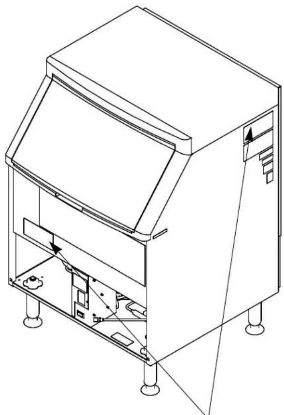
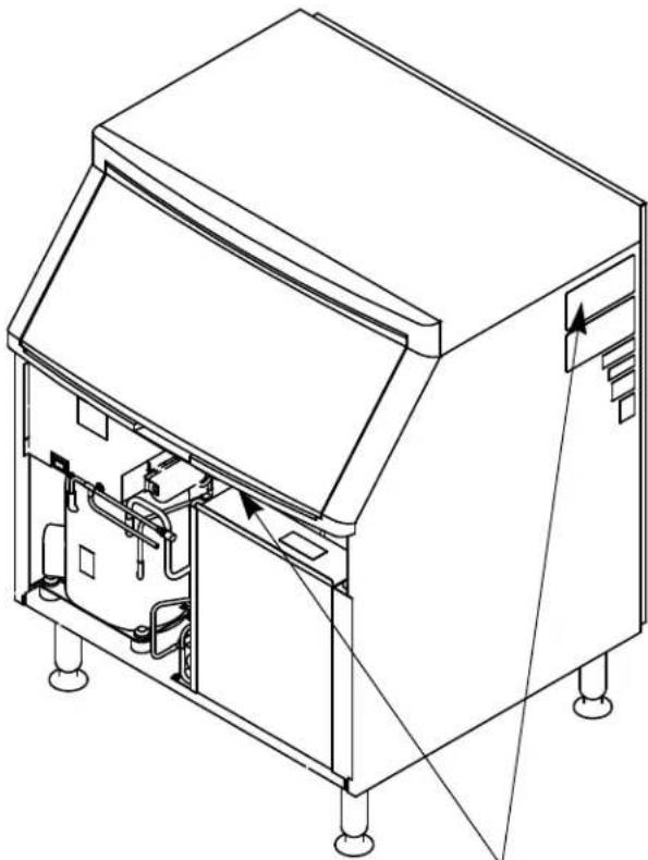
Record the model and serial number of your ice machine in the space provided below. These numbers are required when requesting information from your local Manitowoc distributor, service representative, or Manitowoc Ice, Inc.
The model and serial number are listed on the OWNER WARRANTY REGISTRATION CARD. They are also listed on the MODEL/SERIAL NUMBER DECAL affixed to the ice machine.
Q130/Q210 MODELS Q270 MODELS
natural_image
Technical line drawing of a mechanical device with internal components and mounting feet (no text or symbols)MODEL/SERIAL PLATE LOCATION
natural_image
Technical line drawing of an open industrial machine with internal components and mounting feet (no text or symbols)MODEL/SERIAL PLATE LOCATION
Model/Serial Number Location
| Ice Machine | |
| Model Number | |
| Serial Number |
Owner Warranty Registration Card
General
The packet containing this manual also includes warranty information. Warranty coverage begins the day your new ice machine is installed.
Important
Complete and mail the OWNER WARRANTY REGISTRATION CARD as soon as possible to validate the installation date.
If you do not return your OWNER WARRANTY REGISTRATION CARD, Manitowoc will use the date of sale to the Manitowoc Distributor as the first day of warranty coverage for your new ice machine.
COMMERCIAL WARRANTY COVERAGE
General
The following Warranty outline is provided for your convenience. For a detailed explanation, read the warranty bond shipped with each product.
Contact your local Manitowoc representative or Manitowoc Ice, Inc. if you need further warranty information.
Parts
- Manitowoc warrants the ice machine against defects in materials and workmanship, under normal use and service for three (3) years from the date of original installation.
- The evaporator and compressor are covered by an additional two (2) year (five years total) warranty beginning on the date of the original installation.
Labor
- Labor required to repair or replace defective components is covered for three (3) years from the date of original installation.
- The evaporator is covered by an additional two (2) year (five years total) labor warranty beginning on the date of the original installation.
Exclusions
The following items are not included in the ice machine's warranty coverage:
- Normal maintenance, adjustments and cleaning as outlined in this manual.
- Repairs due to unauthorized modifications to the ice machine or use of non-standard parts without prior written approval from Manitowoc Ice, Inc.
- Damage caused by improper installation of the ice machine, electrical supply, water supply or drainage, or damage caused by floods, storms, or other acts of God.
- Premium labor rates due to holidays, overtime, etc.; travel time; flat rate service call charges; mileage and miscellaneous tools and material charges not listed on the payment schedule. Additional labor charges resulting from the inaccessibility of equipment are also excluded.
- Parts or assemblies subjected to misuse, abuse, neglect or accidents.
- Damage or problems caused by installation, cleaning and/or maintenance procedures inconsistent with the technical instructions provided in this manual.
Authorized Warranty Service
To comply with the provisions of the warranty, a refrigeration service company, qualified and authorized by your Manitowoc distributor, or a Contracted Service Representative must perform the warranty repair.
NOTE: If the dealer you purchased the ice machine from is not authorized to perform warranty service, contact your Manitowoc distributor or Manitowoc Ice, Inc. for the name of the nearest authorized service representative.
Service Calls
Normal maintenance, adjustments and cleaning as outlined in this manual are not covered by the warranty. If you have followed the procedures listed in this manual, and the ice machine still does not perform properly, call your authorized service company.
RESIDENTIAL WARRANTY COVERAGE
WHAT DOES THIS LIMITED WARRANTY COVER?
Subject to the exclusions and limitations below, Manitowoc Ice, Inc. (“Manitowoc”) warrants to the original consumer that any new ice machine manufactured by Manitowoc (the “Product”) shall be free of defects in material or workmanship for the warranty period outlined below under normal use and maintenance, and upon proper installation and start-up in accordance with the instruction manual supplied with the Product.
HOW LONG DOES THIS LIMITED WARRANTY LAST?
Ice Machine - Twelve (12) months from the sale date
WHO IS COVERED BY THIS LIMITED WARRANTY?
This limited warranty only applies to the original consumer of the Product and is not transferable.
WHAT ARE MANITOWOC ICE'S OBLIGATIONS UNDER THIS LIMITED WARRANTY?
If a defect arises and Manitowoc receives a valid warranty claim prior to the expiration of the warranty period, Manitowoc shall, at its option: (1) repair the Product at Manitowoc's cost, including standard straight time labor charges, (2) replace the Product with one that is new or at least as functionally equivalent as the original, or (3) refund the purchase price for the Product. Replacement parts are warranted for 90 days or the balance of the original warranty period, whichever is longer. The foregoing constitutes Manitowoc's sole obligation and the consumer's exclusive remedy for any breach of this limited warranty. Manitowoc's liability under this limited warranty is limited to the purchase price of Product. Additional expenses including, without limitation, service travel time, overtime or premium labor charges, accessing or removing the Product, or shipping are the responsibility of the consumer.
HOW TO OBTAIN WARRANTY SERVICE
To obtain warranty service or information regarding your Product, please contact us at:
MANITOWOC FOODSERVICE
2110 So. 26 ^th St.,
P.O. Box 1720,
Manitowoc, WI 54221-1720
Telephone: 920-682-0161 Fax: 920-683-7585
www.manitowocice.com
WHAT IS NOT COVERED?
This limited warranty does not cover, and you are solely responsible for the costs of: (1) periodic or routine maintenance, (2) repair or replacement of the Product or parts due to normal wear and tear, (3) defects or damage to the Product or parts resulting from misuse, abuse, neglect, or accidents, (4) defects or damage to the Product or parts resulting from improper or unauthorized alterations, modifications, or changes; and (5) defects or damage to any Product that has not been installed and/or maintained in accordance with the instruction manual or technical instructions provided by Manitowoc. To the extent that warranty exclusions are not permitted under some state laws, these exclusions may not apply to you.
EXCEPT AS STATED IN THE FOLLOWING SENTENCE, THIS LIMITED WARRANTY IS THE SOLE AND EXCLUSIVE WARRANTY OF MANITOWOC WITH REGARD TO THE PRODUCT. ALL IMPLIED WARRANTIES ARE STRICTLY LIMITED TO THE DURATION OF THE LIMITED WARRANTY APPLICABLE TO THE PRODUCTS AS STATED ABOVE, INCLUDING BUT NOT LIMITED TO, ANY WARRANTY OF MERCHANTABILITY OR OF FITNESS FOR A PARTICULAR PURPOSE. Some states do not allow limitations on how long an implied warranty lasts, so the above limitation may not apply to you.
IN NO EVENT SHALL MANITOWOC OR ANY OF ITS AFFILIATES BE LIABLE TO THE CONSUMER OR ANY OTHER PERSON FOR ANY INCIDENTAL, CONSEQUENTIAL OR SPECIAL DAMAGES OF ANY KIND (INCLUDING, WITHOUT LIMITATION, LOSS OF PROFITS, REVENUE OR BUSINESS) ARISING FROM OR IN ANY MANNER CONNECTED WITH THE PRODUCT, ANY BREACH OF THIS LIMITED WARRANTY, OR ANY OTHER CAUSE WHATSOEVER, WHETHER BASED ON CONTRACT, TORT OR ANY OTHER THEORY OF LIABILITY. Some states do not allow the exclusion or limitation of incidental or consequential damages, so the above limitation or exclusion may not apply to you.
HOW STATE LAW APPLIES
This limited warranty gives you specific legal rights, and you may also have rights that vary from state to state or from one jurisdiction to another.
REGISTRATION CARD
To secure prompt and continuing warranty service, this warranty registration card must be completed and sent to Manitowoc within thirty (30) days from the sale date. Complete the following registration card and send it to Manitowoc at the address shown.
Section 2 Installation Instructions
General
These instructions are provided to assist the qualified installer.
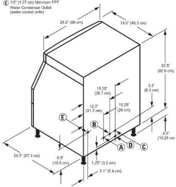
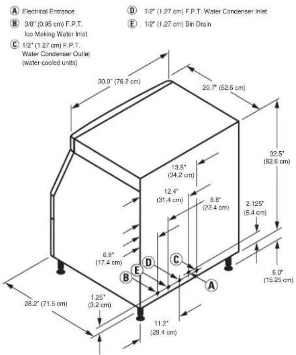
Ice Machine Dimensions Q130/Q210 ICE MACHINES Q270 ICE MACHINES
A Electrical Entrance
B 3/8" (0.95 cm) FPT Ice Making Water Inlet
C 1/2" (1.27 cm) Minimum FPT Water Condenser Outlet (water-cooled units)
D 3/8" (0.95 cm) FPT Water Condenser Inlet E 1/2" (1.27 cm) FPT Bin Drain
Important
Failure to follow these installation guidelines may affect warranty coverage.
Location of Ice Machine
The location selected for the ice machine must meet the following criteria. If any of these criteria are not met, select another location.
• The location must be indoors.
- The location must be free of airborne and other contaminants.
- The air temperature must be at least 40^ F ( 4.4^ C), but must not exceed 110^ F ( 43.4^ C).
- The location must not be near heat-generating equipment or in direct sunlight.
- The location must be capable of supporting the weight of the ice machine and a full bin of ice.
- The location must allow enough clearance for water, drain and electrical connections in the rear of the ice machine.
- The location must not obstruct airflow through or around the ice machine (condenser airflow is in and out the front). Refer to the chart below for clearance requirements.
| Self-Contained Air-Cooled | Self-Contained Water-Cooled | |
| Top/Sides 5" (203 mm)* 5" (127 mm)* | ||
| Back 5" (127 mm)* 5" (127 mm)* | ||
NOTE: The ice machine may be built into a cabinet.
There is no minimum clearance requirement for the top or left and right sides of the ice machine. The listed values are recommended for efficient operation and servicing only.
Caution
The ice machine must be protected if it will be subjected to temperatures below 32^ F ( 0^ C). Failure caused by exposure to freezing temperatures is not covered by the warranty. See “Removal from Service/Winterization” Section 4.
Ice Machine Heat of Rejection
| Series Ice Machine | Heat of Rejection* | |
| Air Conditioning** | Peak | |
| Q130 2400 | 2900 | |
| Q210 2400 | 3400 | |
| Q270 3800 | 6000 | |
* B.T.U./Hour
** Because the heat of rejection varies during the ice making cycle, the figure shown is an average.
Ice machines, like other refrigeration equipment, reject heat through the condenser. It is helpful to know the amount of heat rejected by the ice machine when sizing air conditioning equipment where self-contained air-cooled ice machines are installed.
Leveling the Ice Machine
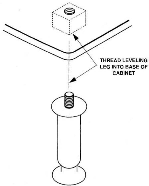
- Screw the leveling legs onto the bottom of the ice machine.
- Screw the foot of each leg in as far as possible.
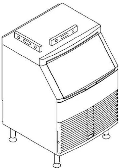
natural_image
Line drawing of a mechanical ice cream oven with vent and side legs (no text or symbols)Checking Ice Machine Level
Caution
The legs must be screwed in tightly to prevent them from bending.
- Move the ice machine into its final position.
- Level the ice machine to assure that the siphon system functions correctly. Use a level on top of the ice machine. Turn each foot as necessary to level the ice machine from front to back and side to side.
NOTE: An optional 2 12 " caster assembly is available for use in place of the legs on the Q130, Q210 and Q270. Installation instructions are supplied with the casters.
Electrical Service
GENERAL

Warning
All wiring must conform to local, state and national codes.
VOLTAGE
The maximum allowable voltage variation is ± 10% of the rated voltage on the ice machine model/serial number plate at start-up (when the electrical load is highest).
The 115/1/60 ice machines are factory pre-wired with a 8' power cord, and NEMA 5-15P-plug configuration.
The 208-230/1/60 and 230/50/1 ice machines are factory pre-wired with a 8' power cord only, no plug is supplied.
FUSE/CIRCUIT BREAKER
A separate fuse/circuit breaker must be provided for each ice machine. Circuit breakers must be H.A.C.R. rated (does not apply in Canada).

Warning
The ice machine must be grounded in accordance with national and local electrical codes.
TOTAL CIRCUIT AMPACITY
The total circuit ampacity is used to help select the wire size of the electrical supply.
The wire size (or gauge) is also dependent upon location, materials used, length of run, etc., so it must be determined by a qualified electrician.
GROUND FAULT CIRCUIT INTERRUPTER
Ground Fault Circuit Interrupter (GFCI/GFI) protection is a system that shuts down the electric circuit (opens it) when it senses an unexpected loss of power, presumably to ground. Manitowoc Ice, Inc. does not recommend the use of a GFCI/GFI circuit protection with our equipment. If code requires the use of a GFCI/GFI then you must follow the local code. The circuit must be dedicated, sized properly and there must be a panel GFCI/GFI breaker. We do not recommend GFCI/GFI outlets as they are known for more intermittent nuisance trips than panel breakers.

Warning
PERSONAL INJURY POTENTIAL
If the supply cord is damaged, do not operate the equipment until the cord is replaced by a service agent or similarly qualified person..
Q130/Q210/Q270 ICE MACHINE
| Ice Machine | Voltage Phase Cycle | Air-Cooled Water Cooled | |||
| Maximum Fuse/Circuit Breaker | Total Amps | Maximum Fuse/Circuit Breaker | Total Amps | ||
| Q130 | 115/1/60 15 7.0 | 15 6.3 | |||
| 208-230/1/60 15 | 3.1 15 2.6 | ||||
| 230/1/50 15 3.0 | 15 2.5 | ||||
| Q210 | 115/1/60 15 6.5 | 15 6.1 | |||
| 208-230/1/60 15 | 3.6 15 3.1 | ||||
| 230/1/50 15 3.6 | 15 3.1 | ||||
| Q270 Danfoss Compressor | 115/1/60 15 10.7 | 15 9.9 | |||
| 208-230/1/60 15 | 5.2 15 4.7 | ||||
| 230/1/50 15 5.2 | 15 4.7 | ||||
| Q270 Tecumseh Compressor | 115/1/60 15 8.5 | 15 7.7 | |||
| 208-230/1/60 15 | 4.5 15 4.0 | ||||
| 230/1/50 15 4.5 | 15 4.0 | ||||
Water Service/Drains
WATER SUPPLY
Local water conditions may require treatment of the water to inhibit scale formation, filter sediment, remove chlorine, and improve taste and clarity.

Warning
PERSONAL INJURY POTENTIAL
For ice making, connect to a potable water supply only.
Important
If you are installing a Manitowoc water filter system, refer to the Installation Instructions supplied with the filter system for ice making water inlet connections.
WATER INLET LINES
Follow these guidelines to install water inlet lines:
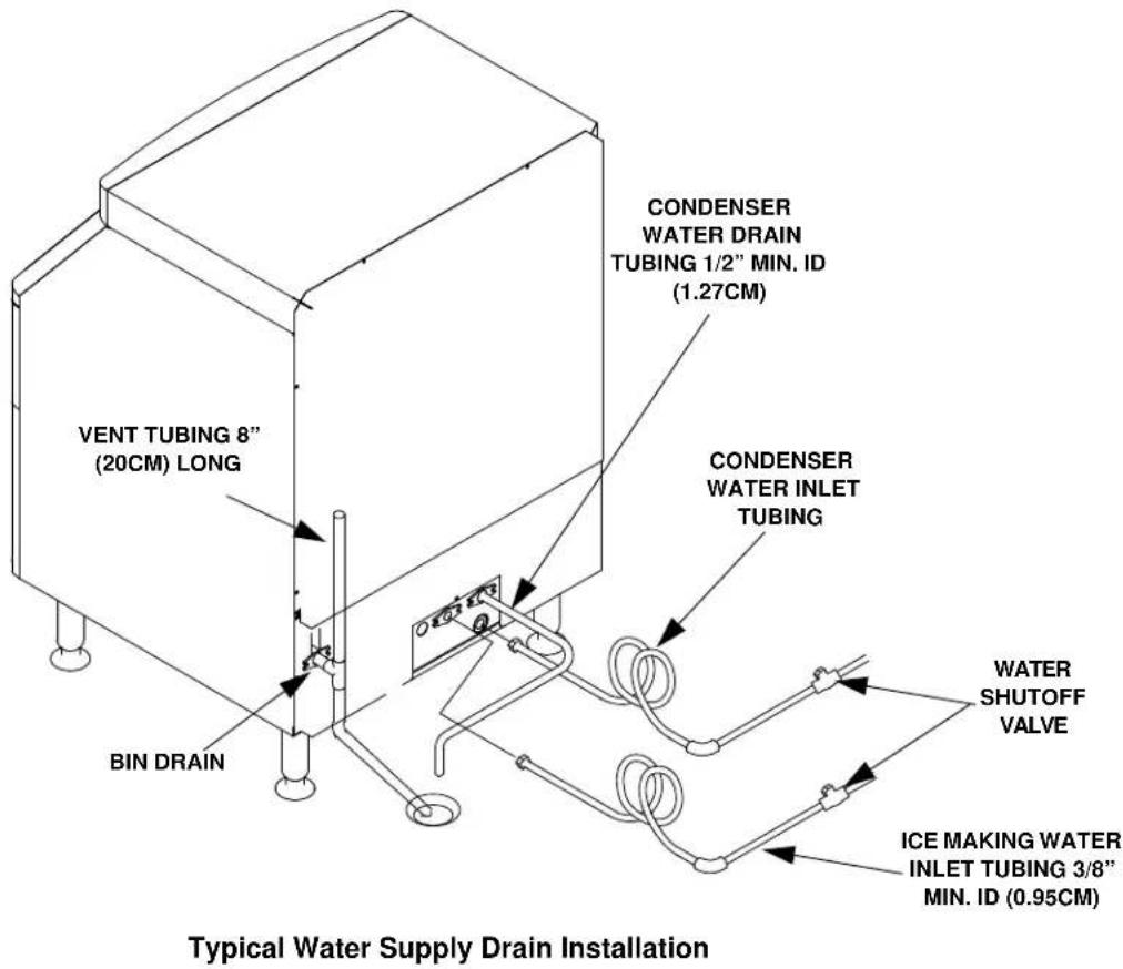
- Do not connect the ice machine to a hot water supply. Be sure all hot water restrictors installed for other equipment are working. (Check valves on sink faucets, dishwashers, etc.)
- If water pressure exceeds the maximum (80 psig-551.5 kPA) recommended pressure, obtain a water pressure regulator from your Manitowoc distributor.
- Install a water shut-off valve and union for both the ice making and condenser water lines.
• Insulate water inlet lines to prevent condensation.
DRAIN CONNECTIONS
Follow these guidelines when installing drain lines to prevent drain water from flowing back into the ice machine and storage bin:
- Drain lines must have a 1.5 inch drop per 5 feet of run (2.5 cm per meter), and must not create traps.
- The floor drain must be large enough to accommodate drainage from all drains.
- Run separate bin and water-cooled condenser drain lines. Insulate them to prevent condensation.
- Vent the bin drain to the atmosphere. Do not vent the condenser drain on water-cooled models.
COOLING TOWER APPLICATIONS
(Water-Cooled Models)
A water cooling tower installation does not require modification of the ice machine. The water regulator valve for the condenser continues to control the refrigeration discharge pressure.
It is necessary to know the amount of heat rejection and the pressure drop through the condenser and water valves (inlet and outlet) when using a cooling tower on an ice machine.
- Water entering the condenser must not exceed 90^ (32.2°C).
- Water flow through the condenser must not exceed 5 gallons (19 liters) per minute.
- Allow for a pressure drop of 7 psi (48 kPA) between the condenser water inlet and the outlet of the ice machine.
- Water exiting the condenser must not exceed 110°F (43.3°C).
Important
The Commonwealth of Massachusetts requires that all water-cooled models must be connected only to a closed loop, cooling tower system.
Water Supply and Drain Line Sizing/Connections

Caution
Plumbing must conform to state and local codes.
| Location | Water Temperature | Water Pressure | Ice Machine Fitting | Tubing Size Up to Ice Machine Fitting |
| Ice Making Water Inlet | 40°F (4.4°C) Min.90°F (32.2°C) Max. | 20 psi (137.9 kPA) Min.80 psi (551.5 kPA) Max. | 3/8" Female Pipe Thread | 3/8" (9.5 mm) minimum inside diameter |
| Condenser Water Inlet | 40°F (4.4°C) Min.90°F (32.2°C) Max. | 20 psi (137.9 kPA) Min.150 psi (1034.2 kPA) Max. | 3/8" Female Pipe ThreadQ270 Only1/2" Female Pipe Thread | 3/8" (9.5 mm) minimum inside diameterQ270 Only1/2" (12.7 mm) minimum inside diameter |
| Condenser Water Drain | --- --- 1/2" Female Pipe | Thread | 1/2" (12.7 mm) minimum inside diameter | |
| Bin Drain | --- --- 1/2" Female Pipe | Thread | 1/2" (12.7 mm) minimum inside diameter | |
Before Starting the Ice Machine
All Manitowoc ice machines are factory-operated and adjusted before shipment. Normally, new installations do not require any adjustment.
To ensure proper operation, follow the Operational Checks in Section 3 of this manual. Starting the ice machine and completing the Operational Checks are the responsibilities of the owner/operator.
Adjustments and maintenance procedures outlined in this manual are not covered by the warranty.

Warning
PERSONAL INJURY POTENTIAL
Do not operate equipment that has been misused, abused, neglected, damaged, or altered/modified from that of original manufactured specifications.
Installation Checklist
Is the ice machine level?
Has all of the internal packing been removed?
Have all of the electrical and water connections been made?
Has the supply voltage been tested and checked against the rating on the nameplate?
Is there proper clearance around the ice machine for air circulation?
Is the ice machine grounded and polarity correct?
Has the ice machine been installed where ambient temperatures will remain in the range of 40^-110^ F ( 4.4^-43.3^ C)?
Has the ice machine been installed where the incoming water temperature will remain in the range of 40^-90^ ( 4.4^-32.2^ )?
Is there a separate drain for the water-cooled condenser?
Is there a separate drain for the bin?
Are the ice machine and bin drains vented?
Are all electrical leads free from contact with refrigeration lines and moving equipment?
Has the owner/operator been instructed regarding maintenance and the use of Manitowoc Cleaner and Sanitizer?
Has the owner/operator completed the warranty registration card?
Has the ice machine and bin been sanitized?
Is the toggle switch set to ice? (The toggle switch is located directly behind the front panel).
Is the ice thickness control set correctly? (Refer to Operational Checks to check/set the correct ice bridge thickness).
Is the float valve in the OPEN position?
Section 3
Operation
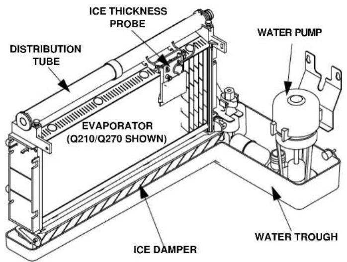
Component Identification
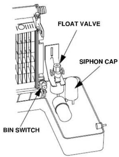
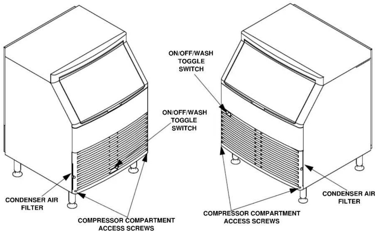
Ice Making Sequence of Operation
INITIAL START-UP OR START-UP AFTER AUTOMATIC SHUT-OFF
1. Pressure Equalization
Before the compressor starts the hot gas valve is energized for 15 seconds to equalize pressures during the initial refrigeration system start-up.
2. Refrigeration System Start-Up
The compressor starts after the 15-second pressure equalization, and remains on throughout the entire Freeze and Harvest Sequences. The hot gas valve remains on for 5 seconds during initial compressor start-up and then shuts off.
At the same time the compressor starts, the condenser fan motor (air-cooled models) is supplied with power throughout the entire Freeze and Harvest Sequences. The fan motor is wired through a fan cycle pressure control, therefore it may cycle on and off. (The compressor and condenser fan motor are wired through the relay. As a result, any time the relay coil is energized, the compressor and fan motor are supplied with power.)
FREEZE SEQUENCE
3. Prechill
The compressor is on for 30 seconds prior to water flow to Prechill the evaporator.
4. Freeze
The water pump starts after the 30-second Prechill. An even flow of water is directed across the evaporator and into each cube cell, where it freezes.
When sufficient ice has formed, the water flow (not the ice) contacts the ice thickness probe. After approximately 7 seconds of continual water contact, the Harvest Sequence is initiated. The ice machine cannot initiate a Harvest Sequence until a 6-minute freeze time has been surpassed.
HARVEST SEQUENCE
5. Harvest
The water pump de-energizes stopping flow over the evaporator. The rising level of water in the sump trough diverts water out of the overflow tube, purging excess minerals from the sump trough. The hot gas valve also opens to divert hot refrigerant gas into the evaporator.
The refrigerant gas warms the evaporator causing the cubes to slide, as a sheet, off the evaporator and into the storage bin. The sliding sheet of cubes contacts the ice damper, opening the bin switch.
The momentary opening and re-closing of the bin switch terminates the Harvest Sequence and returns the ice machine to the Freeze Sequence (steps 3 - 4).
AUTOMATIC SHUT-OFF
6. Automatic Shut-Off
When the storage bin is full at the end of a Harvest Sequence, the sheet of cubes fails to clear the ice damper and will hold it down. After the ice damper is held open for 7 seconds, the ice machine shuts off. The ice machine remains off for 3 minutes before it can automatically restart.
The ice machine remains off until enough ice has been removed from the storage bin to allow the ice to fall clear of the damper. As the ice damper swings back to the operating position, the bin switch re-closes and the ice machine restarts (steps 1 - 2), provided the 3-minute delay period is complete.
Section 3 Operation
Energized Parts Chart
| CONTROL BOARD RELAYS | RELAY | ||||||
| 1WATERPUMP | 2HOT GASVALVE | RELAYCOIL | 3COMPRESSOR | 3CONDENSER *FAN MOTOR | Aof “ON” TIME | ||
| INITIAL START-UP/START UP AFTER AUTO SHUT-OFF: | OFF ON OFF OFF | OFF | 15Seconds | ||||
| 1. Pressure Equalization | |||||||
| 2. Refrigeration System Start-up FREEZE | OFF ON | ON | ON | ON | 5Seconds | ||
| SEQUENCE: | OFF | OFF ON | ON | ON | 30Seconds | ||
| 3. Pre-Chill | |||||||
| 4. Freeze | ON | OFF | ON | ON | ON | Until 7 sec.water contact with ice thickness probe | |
| HARVEST SEQUENCE: | OFF ON | ON | ON | ON | Bin switch activation | ||
| 5. Harvest | |||||||
| AUTOMATIC SHUT-OFF: | OFF | OFF OFF OFF | OFF | Until bin switch re-closes | |||
| 6. Auto Shut-Off | |||||||
* Condenser Fan Motor: The fan motor is wired through a fan cycle pressure control, therefore, it may cycle on and off.
Operational Checks
GENERAL
Your Manitowoc ice machine was factory-operated and adjusted before shipment. Normally, a newly installed ice machine does not require any adjustment.
To ensure proper operation, always follow these Operational Checks when starting the ice machine:
• for the first time
• after a prolonged out of service period
• after cleaning and sanitizing
Routine adjustments and maintenance procedures outlined in this manual are not covered by the warranty.
SIPHON SYSTEM
To reduce mineral build-up and cleaning frequency, the water in the sump trough must be purged during each harvest cycle.
When the water pump de-energizes the level in the water trough rises above the standpipe starting a siphon action. The siphon action stops when the water level in the sump trough drops. When the siphon action stops, the float valve refills the water trough to the correct level.
Siphon System Check
Follow steps 1 through 6 under water level check.
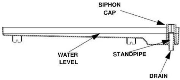
WATER FLOAT VALVE CHECK
Before water will flow into the water trough the float valve shut-off must be in the OPEN position.
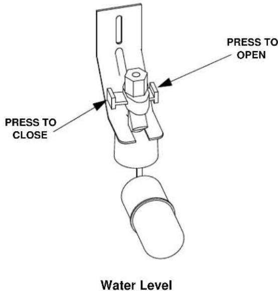
WATER LEVEL CHECK
Check the water level while the ice machine is in the ice mode and the water pump is running. The correct water level is 1/4"(6.3mm) to 3/8" (9.5mm) below the top of the standpipe a line in the water trough indicates the correct level.
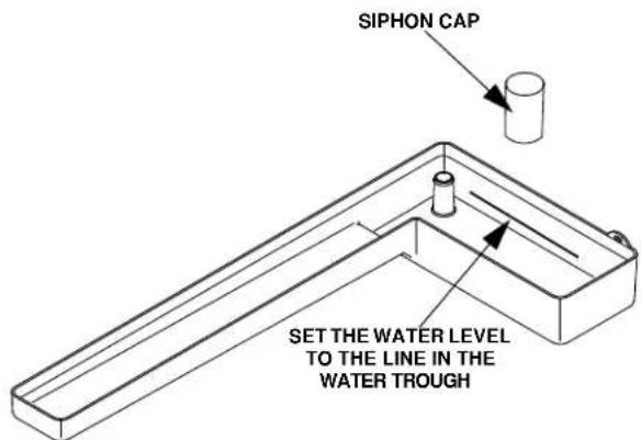
Water Level
The float valve is factory-set for the proper water level. If adjustments are necessary:
- Verify the ice machine is level (see page 2-4).
- Remove the siphon cap from the standpipe.
- Place the main ON/OFF/WASH toggle switch to the ON position, and wait until the float valve stops adding water.
- Adjust the water level to (1/4" to 3/8" (6.3 to 9.5 mm) below the standpipe) the line in the water trough:
- Loosen the two screws on the float valve bracket.
- Raise or lower the float valve assembly as necessary, then tighten the screws.
- Move the main ON/OFF/WASH toggle switch to the OFF position. The water level in the trough will rise above the standpipe and run down the drain.
- Replace the siphon cap on the standpipe, and verify water level and siphon action by repeating steps 3 through 5.
ICE BRIDGE THICKNESS CHECK
The ice thickness probe is factory-set to maintain the ice bridge thickness at 1/8" (3.2 mm).
- Inspect the bridge connecting the cubes. It should be about 1/8" (3.2 mm) thick.
- If adjustment is necessary, turn the ice thickness probe adjustment screw clockwise to increase bridge thickness, or counterclockwise to decrease bridge thickness.
NOTE: Turning the adjustment 1/3 of a turn will change the ice thickness about 1/16" (1.5 mm).
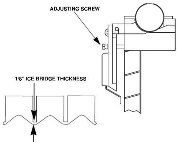
Ice Thickness Check
Make sure the ice thickness probe wire and the bracket do not restrict movement of the probe.
THIS PAGE INTENTIONALLY LEFT BLANK
Section 4
Maintenance
Interior Cleaning and Sanitizing
GENERAL
Clean and sanitize the ice machine every six months for efficient operation. If the ice machine requires more frequent cleaning and sanitizing, consult a qualified service company to test the water quality and recommend appropriate water treatment.
The ice machine must be taken apart for cleaning and sanitizing.
Caution
Use only Manitowoc approved Ice Machine Cleaner (part number 94-0546-3) and Sanitizer (part number 94-0565-3). It is a violation of Federal law to use these solutions in a manner inconsistent with their labeling. Read and understand all labels printed on bottles before use.
CLEANING AND SANITIZING PROCEDURE
Caution
Do not mix Ice Machine Cleaner and Sanitizer solutions together. It is a violation of Federal law to use these solutions in a manner inconsistent with their labeling.
Warning
Wear rubber gloves and safety goggles (and/or face shield) when handling Ice Machine Cleaner or Sanitizer.
Ice machine cleaner is used to remove lime scale and mineral deposits. Ice machine sanitizer disinfects and removes algae and slime.
Step 1 Set the toggle switch to the OFF position after ice falls from the evaporator at the end of a Harvest cycle. Or, set the switch to the OFF position and allow the ice to melt off the evaporator.
Caution
Never use anything to force ice from the evaporator. Damage may result.
Step 2 Remove all ice from the bin.
Step 3 To start a cleaning cycle, move the toggle switch to the WASH position.
Step 4 Add the proper amount of Manitowoc Ice Machine Cleaner to the water trough.
| Model Amount of Cleaner | |
| Q130 1 ounces (30 ml) | |
| Q210 2 ounces (60 ml) | |
| Q270 2 ounces (60 ml) |
Step 5 Wait until the clean cycle is complete (approximately 22 minutes) then place the toggle switch in the OFF position, disconnect power and water supplies to the ice machine.
Warning
Disconnect electric power to the ice machine at the electric switch box before proceeding.
Step 6 Remove parts for cleaning.
A. Remove the Vinyl Hose
- Disconnect the water hose from the distribution tube and water pump.
B. Remove Water Pump
- Disconnect the water pump power cord.
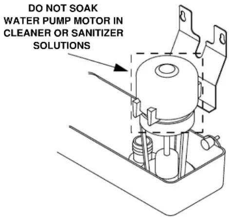
Water Pump Removal
- Loosen the screws securing the pump-mounting bracket to the bulkhead.
- Lift the pump and bracket assembly off the mounting screws.
C. Remove the Ice Thickness Probe
- Compress the side of the ice thickness probe near the top hinge pin and remove it from the bracket.
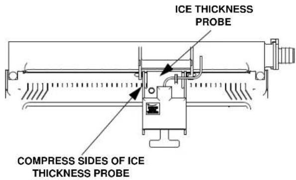
Ice Thickness Probe Removal
NOTE: At this point, the ice thickness probe can easily be cleaned. If complete removal is desired follow the ice thickness probe wire to the bulkhead grommet (exit point) in the back wall. Pop the bulkhead grommet out of the back wall by inserting fingernails or a flat object between the back wall and the grommet and prying forward. Pull the bulkhead grommet and wire forward until the connector is accessible, then disconnect the wire lead from the connector.
Ice Thickness Probe Cleaning
- Mix a solution of Manitowoc ice machine cleaner and water (2 ounces of cleaner to 16 ounces of water) in a container.
- Soak the ice thickness probe a minimum of 10 minutes.
Clean all ice thickness probe surfaces and verify the ice thickness probe cavity is clean. Rinse thoroughly with clean water, then dry completely. Incomplete rinsing and drying of the ice thickness probe can cause premature harvest.
D. Remove the Water Distribution Tube
Q210/Q270 Models
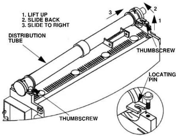
Q210/Q270 Water Distribution Tube Removal
- Loosen the two thumbscrews, which secure the distribution tube.
- Lift the right side of the distribution tube up off the locating pin, then slide it back and to the right.

Caution
Do not force this removal. Be sure the locating pin is clear of the hole before sliding the distribution tube out.
Disassembly
- Twist both of the inner tube ends until the tabs line up with the keyways.
- Pull the inner tube ends outward.
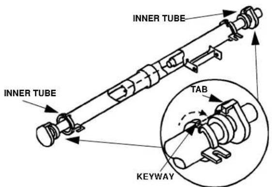
Q210/Q270 Water Distribution Tube Disassembly
Q130 Models
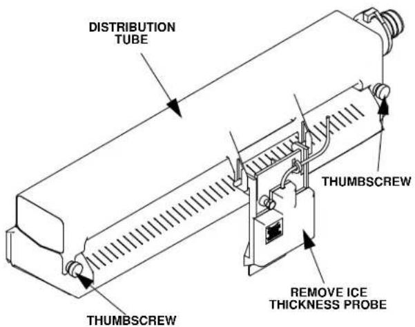
Q130 Water Distribution Tube Removal
- Loosen the two thumbscrews, which secure the distribution tube.
- Lift the distribution tube up off the thumbscrews.
Disassembly
- Twist the barbed end until the tab lines up with the keyway.
- Pull the inner tube end outward.
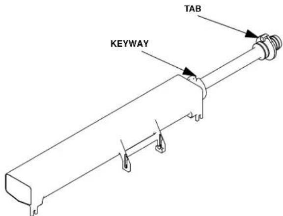
Q130 Water Distribution Tube Disassembly
E. Remove the Float Valve
- Turn the splash shield counterclockwise one or two turns.
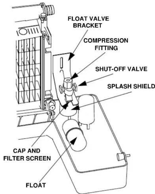
Float Valve Removal
- Pull the float valve forward and off the mounting bracket.
- Disconnect the water inlet tube from the float valve at the compression fitting.
- Remove the cap and filter screen for cleaning.
F. Remove the Water Trough
- Apply downward pressure on the siphon tube and remove from the bottom of the water trough.
- Remove the upper thumbscrew.
- While supporting the water trough remove the two thumbscrews from beneath the water trough.
- Remove the water trough from the bin area.
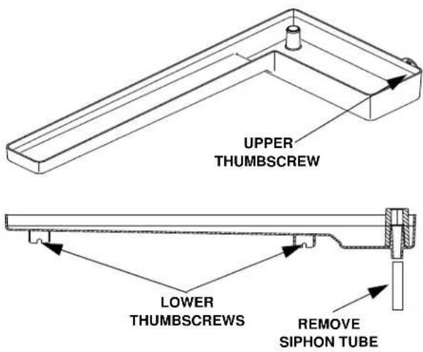
G. Remove the ice damper.
Q130
- Grasp left side of ice damper and apply pressure against the right-hand ice damper mounting bracket.
- Pull forward on the ice damper until the left-hand mounting pin disengages.
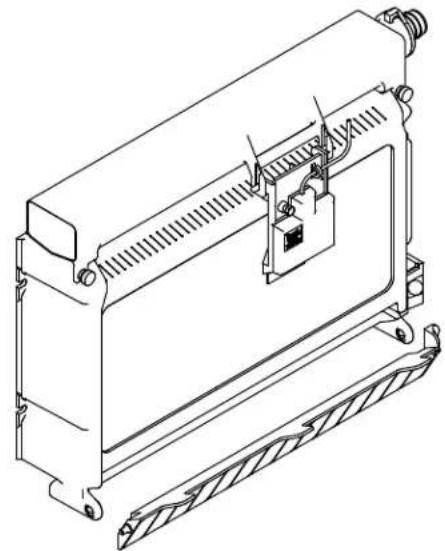
natural_image
Technical line drawing of a mechanical device with no visible text or symbolsInstallation
- Grasp the right side of ice damper and place left hand pin in the mounting bracket.
- While applying pressure against the left-hand mounting bracket push the damper until the right-hand mounting pin engages.
Q210/Q270
- Grasp ice damper and apply pressure toward the left hand mounting bracket.
- Apply pressure to the right hand mounting bracket with thumb.
- Pull ice damper forward when the right hand ice damper pin disengages.
Installation
- Place ice damper pin in left hand mounting bracket and apply pressure toward the left hand mounting bracket.
- Apply pressure to the right hand mounting bracket with thumb.
- Push ice damper toward evaporator until right hand damper pin engages.
H. Remove the Bin Door
- Grasp the rear of the bin door and pull bin door forward approximately 5".
- Slide bin door to the rear while applying upward pressure (The rear door pins will ride up into the track slot and slide backward to the stop tab).
- While applying pressure against the bin door pull down on the rear of each bin door track until the door pins clear the stop tabs.
- Slide the rear door pins off the end and then below the door track. Slide bin door forward allowing the back of the door to lower into the bin. Continue forward with the bin door until the front pins bottom out in the track.
- Lift right side of door until the front pins clear the track, then remove door from bin.
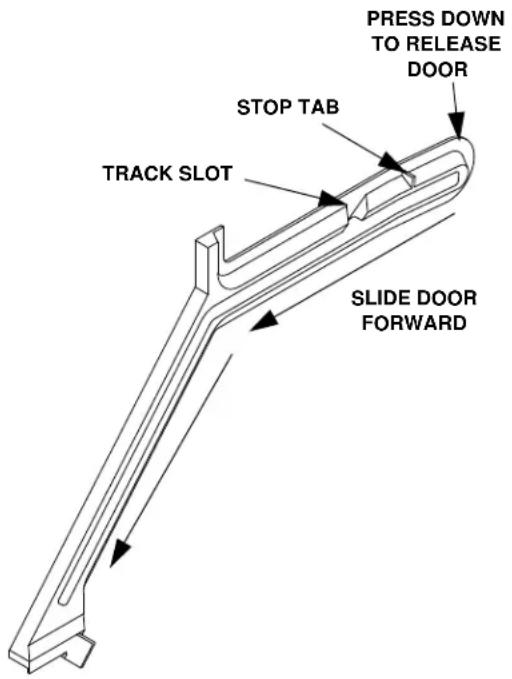
Step 7 Mix a solution of cleaner and warm water.
Depending on the amount of mineral buildup, a larger quantity of solution may be required. Use the ratio in the table below to mix enough solution to thoroughly clean all parts.
| Solution Type | Water Mixed with |
| Cleaner 1 gal. (4 l) | 16 oz (500 ml) cleaner |
Step 8 Use 12 of the cleaner/water solution to clean all components. The cleaner solution will foam when it contacts lime scale and mineral deposits; once the foaming stops use a soft bristle brush, sponge or cloth (not a wire brush) to carefully clean the parts. Soak the parts for 5 minutes (15 – 20 minutes for heavily scaled parts). Rinse all components with clean water.
Step 9 While components are soaking, use 12 of the cleaner/water solution to clean all foodzone surfaces of the ice machine and bin. Use a nylon brush or cloth to thoroughly clean the following ice machine areas:
- Evaporator plastic parts – including top, bottom and sides
- Bin bottom, sides and top
Rinse all areas thoroughly with clean water.
Step 10 Mix a solution of sanitizer and warm water.
| Solution Type | Water Mixed With |
| Sanitizer 6 gal. (23 l) | 4 oz (120 ml) sanitizer |
Step 11 Use 1/2 of the sanitizer/water solution to sanitize all removed components. Use a cloth or sponge to liberally apply the solution to all surfaces of the removed parts or soak the removed parts in the sanitizer/water solution. Do not rinse parts after sanitizing.
Step 12 Use 1/2 of the sanitizer/water solution to sanitize all foodzone surfaces of the ice machine and bin. Use a cloth or sponge to liberally apply the solution. When sanitizing, pay particular attention to the following areas:
- Evaporator plastic parts - including top, bottom and sides
- Bin bottom, sides and top
Do not rinse the sanitized areas.
Step 13 Replace all removed components.
Step 14 Reapply power and water to the ice machine and place the toggle switch in the WASH position.
Step 15 Add the proper amount of Manitowoc Ice Machine Sanitizer to the water trough.
| Model Amount of Sanitizer | |
| Q130 1.6 ounces | (48 ml) |
| Q210 2.2 ounces | (66 ml) |
| Q270 1.9 ounces | (57 ml) |
Step 16 Wait until the sanitize cycle is complete (approximately 22 minutes) then place the toggle switch in the OFF position, disconnect power and water supplies to the ice machine.
Warning
Disconnect electric power to the ice machine at the electric switch box before proceeding.
Step 17 Repeat step 6 to remove parts for hand sanitizing.
Step 18 Mix a solution of sanitizer and warm water.
Solution Type Water Mixed With
Sanitizer 6 gal. (23 l) 4 oz (120 ml) sanitizer
Step 19 Use 1/2 of the sanitizer/water solution to sanitize all removed components. Use a cloth or sponge to liberally apply the solution to all surfaces of the removed parts or soak the removed parts in the sanitizer/water solution. Do not rinse parts after sanitizing.
Step 20 Use 1/2 of the sanitizer/water solution to sanitize all foodzone surfaces of the ice machine and bin. Use a cloth or sponge to liberally apply the solution. When sanitizing, pay particular attention to the following areas:
- Evaporator plastic parts - including top, bottom and sides
- Bin bottom, sides and top
Do not rinse the sanitized areas.
Step 21 Replace all removed components.
Step 22 Reapply power and water to the ice machine and place the toggle switch in the ICE position.
ICE MACHINE INSPECTION
Check all water fittings and lines for leaks. Also, make sure the refrigeration tubing is not rubbing or vibrating against other tubing, panels, etc.
Do not put anything (boxes, etc.) in front of the ice machine. There must be adequate airflow through and around the ice machine to maximize ice production and ensure long component life.
EXTERIOR CLEANING
Clean the area around the ice machine as often as necessary to maintain cleanliness and efficient operation.
Sponge any dust and dirt off the outside of the ice machine with mild soap and water. Wipe dry with a clean, soft cloth.
A commercial grade stainless steel cleaner/polish can be used as necessary.
CLEANING THE CONDENSER
Warning
Disconnect electric power to the ice machine at the electric service switch before cleaning the condenser.
Air-Cooled Condenser
A dirty condenser restricts airflow, resulting in excessively high operating temperatures. This reduces ice production and shortens component life. Clean the condenser at least every six months. Follow the steps below.
Warning
The condenser fins are sharp. Use care when cleaning them.
- The washable aluminum filter on self-contained ice machines is designed to catch dust, dirt, lint and grease. This helps keep the condenser clean. Clean the filter with a mild soap and water solution.
- Clean the outside of the condenser with a soft brush or a vacuum with a brush attachment. Clean from top to bottom, not side to side. Be careful not to bend the condenser fins.
- Shine a flashlight through the condenser to check for dirt between the fins. If dirt remains: Blow compressed air through the condenser fins from the inside. Be careful not to bend the fan blades.
- Use a commercial condenser coil cleaner. Follow the directions and cautions supplied with the cleaner.
- Straighten any bent condenser fins with a fin comb.
- Carefully wipe off the fan blades and motor with a soft cloth. Do not bend the fan blades. If the fan blades are excessively dirty, wash with warm, soapy water and rinse thoroughly.
Caution
If you are cleaning the condenser fan blades with water, cover the fan motor to prevent water damage.
Water-Cooled Condenser and Water Regulating Valve
The water-cooled condenser and water regulating valve may require cleaning due to scale build-up.
Low ice production, high water consumption and high operating temperatures and pressures all may be symptoms of restrictions in the condenser water circuit.
Because the cleaning procedures require special pumps and cleaning solutions, they must be performed by qualified maintenance or service personnel.
Removal From Service Winterization
Special precautions must be taken if the ice machine is to be removed from service for an extended period of time or exposed to ambient temperatures of 32^ F ( 0^ C) or below.
Caution
If water is allowed to remain in the ice machine in freezing temperatures, severe damage to some components could result. Damage of this nature is not covered by the warranty.
Follow the applicable procedure below.
SELF-CONTAINED AIR-COOLED ICE MACHINES
- Disconnect the electric power at the circuit breaker or the electric service switch.
- Turn off the water supply.
- Remove the water from the water trough.
- Disconnect and drain the incoming ice-making water line at the rear of the ice machine.
- Blow compressed air in both the incoming water and the drain openings in the rear of the ice machine until no more water comes out of the inlet water lines or the drain.
- Make sure water is not trapped in any of the water lines, drain lines, distribution tubes, etc.
WATER-COOLED ICE MACHINES
Perform steps 1-6 under "Self-Contained Air-Cooled Ice Machines."
- Disconnect the incoming water and drain lines from the water-cooled condenser.
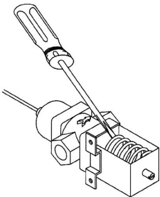
- Insert a large screwdriver between the bottom spring coils of the water regulating valve. Pry upward to open the valve.
natural_image
Technical line drawing of a mechanical tool with a screwdriver and spring-loaded component (no text or symbols)Pry Open the Water Regulating Valve
- Hold the valve open and blow compressed air through the condenser until no water remains.
THIS PAGE INTENTIONALLY LEFT BLANK
THIS PAGE INTENTIONALLY LEFT BLANK
Section 5
Before Calling for Service
Checklist
If a problem arises during operation of your ice machine, follow the checklist below before calling service. Routine adjustments and maintenance procedures are not covered by the warranty.
| Problem Possible Cause | Use To Correct | |
| Ice machine does not operate. | No electrical power to the ice machine. | Replace the fuse/reset the breaker/turn on the main switch/plug power cord into receptacle. |
| ON/OFF/WASH toggle switch set improperly. | Move the toggle switch to the ON position. | |
| Damper in open position (down). Damper must be in upright position and capable of swinging freely. | ||
| Ice machine stops, and can be restarted by moving the toggle switch to OFF and back to ICE. | Safety limit feature stopping the ice machine. | Refer to “Safety Limit Feature” on the next page. |
| Ice machine does not release ice or is slow to harvest. | Ice machine is dirty. Clean and sanitize the ice machine. | |
| Ice machine is not level. Level the ice machine. | ||
| Low air temperature around ice machine (air-cooled models). | Air temperature must be at least 40°F (4.4°C). | |
| Water regulating valve leaks in harvest mode (water-cooled models). | Replace water regulating valve. | |
| Ice machine does not cycle into harvest mode. | The six-minute freeze time lock-in has not expired yet. | Wait for freeze lock-in to expire. |
| Ice thickness probe is dirty. Clean and sanitize the ice machine. | ||
| Ice thickness probe wire is disconnected. Connect the wire. | ||
| Ice thickness probe is out of adjustment. Adjust the ice thickness probe. | ||
| Uneven ice fill (thin at top of evaporator). | See “Shallow or Incomplete Cubes” on the next page. | |
| Ice quality is poor (soft or not clear). | Poor incoming water quality. | Contact a qualified service company to test the quality of the incoming water and make appropriate filter recommendations. |
| Water filtration is poor. | Replace the filter. | |
| Ice machine is dirty. Clean and sanitize the ice machine. | ||
| Water siphon is not working. | Check the water siphon system. | |
| Water softener is working improperly (if applicable). | Repair the water softener. | |
Continued on next page...
| Problem Possible Cause To Correct | ||
| Ice machine produces shallow or incomplete cubes, or the ice | Ice thickness probe is out of adjustment. Adjust the ice thickness probe. | |
| fill pattern on the evaporator is incomplete. | Water trough level is to high or too low. Check the water level. | |
| Water float valve filter screen is dirty. Remove and clean the filter screen. | ||
| Water filtration is poor. Replace the filter. | ||
| Hot incoming water. Connect the ice machine to a cold water supply. | ||
| Water float valve is not working. Remove the water float valve and clean it. | ||
| Incorrect incoming water pressure. Water pressure must be 20-80 psi (137.9 - 551.5 kPA). | ||
| Ice machine is not level. | Level the ice machine. | |
| Low ice capacity. | Water float valve filter screen is dirty. | Remove and clean the filter screen. |
| Incoming water supply is shut off. | Open the water service valve. | |
| Water float valve stuck open or leaking. | Remove the water float valve and clean it. | |
| The condenser is dirty. | Clean the condenser. | |
| High air temperature around ice machine (air-cooled models). | Air temperature must not exceed 110°F (43.3°C). | |
| Inadequate clearance around the ice machine. | Provide adequate clearance. | |
| Objects stacked around ice machine, blocking airflow to condenser (air-cooled models). | Remove items blocking airflow. | |
Safety Limit Feature
In addition to the standard safety controls, your Manitowoc ice machine features built-in safety limits that will stop the ice machine if conditions arise which could cause a major component failure.
Before calling for service, re-start the ice machine using the following procedure:
- Move the ON/OFF/WASH switch to OFF and then back to ON.
A. If the safety limit feature has stopped the ice machine, it will restart after a short delay. Proceed to step 2.
B. If the ice machine does not restart, see "Ice machine does not operate" on the previous page.
- Allow the ice machine to run to determine if the condition is reoccurring.
A. If the ice machine stops again, the condition has reoccurred. Call for service.
B. If the ice machine continues to run, the condition has corrected itself. Allow the ice machine to continue running.
SAFETY LIMITS
General
In addition to standard safety controls, the control board has two built in safety limit controls which protect the ice machine from major component failures.
Safety Limit #1: If the freeze time reaches 60 minutes, the control board automatically initiates a harvest cycle. If three consecutive 60-minute freeze cycles occur, the ice machine stops.
Safety Limit #2: If the harvest time reaches 3.5 minutes, the control board automatically returns the ice machine to the freeze cycle. If three consecutive 3.5 minute harvest cycles occur, the ice machine stops.
Safety Limit Stand-By Mode:
The first time a safety limit shut down occurs, the ice machine turns off for 60 minutes (Stand-by Mode). The ice machine will then automatically restart to see if the problem reoccurs. During the Stand-By Mode the harvest light will be flashing continuously and a safety limit indication can be viewed. If the same safety limit is reached a second time (the problem has reoccurred) the ice machine will initiate a safety limit shut down and remain off until it is manually restarted. During a safety limit shut down the harvest light will be flashing continuously.
Determining Which Safety Limit Stopped The Ice Machine
When a safety limit condition causes the ice machine to stop, the harvest light on the control board continually flashes on and off. Use the following procedures to determine which safety limit has stopped the ice machine.
- Move the toggle switch to OFF.
- Move the toggle switch back to ON.
- Watch the harvest light. It will flash one or two times, corresponding to safety limits 1 and 2, to indicate which safety limit stopped the ice machine.
After safety limit indication, the ice machine will restart and run until a safety limit is exceeded again.
Safety Limit Notes
- A safety limit indication is completed before the water pump starts. Water contacting the ice thickness probe in the freeze cycle will cause the harvest light to flash. Do not mistake a harvest light flashing in the freeze cycle with a safety limit indication.
- A continuous run of 100 harvests automatically erases the safety limit code.
- The control board will store and indicate only one safety limit – the last one exceeded.
- If the toggle switch is moved to the OFF position and then back to the ON position prior to reaching the 100-harvest point, the last safety limit exceeded will be indicated.
- If the harvest light did not flash prior to the ice machine restarting, then the ice machine did not stop because it exceeded a safety limit.
Safety Limit #1
Freeze time exceeds 60 minutes for 3 consecutive freeze cycles.
| Possible Cause Check/Correct | |
| Improper installation See “Installation In | Instructions” Section 2 of this manual |
| Water system Low water pressure (20 psi minimum.) | High water pressure (80 psi maximum.)High water temperature (90°F/32.2°C maximum.)Clogged water distribution tubeDirty/defective water float valveLoss of water from sump areaDefective water pump |
| Electrical system Ice thickness probe out of adjustment | Harvest cycle not initiated electricallyCompressor relay not energizingCompressor electrically non-operational |
| Restricted condenser air flow (air-cooled models) | High inlet air temperature (110°F/43.3°C maximum.)Condenser discharge air recirculationDirty condenser filterDirty condenser finsDefective fan cycling controlDefective fan motor |
| Refrigeration system Non-Manitowoc components | Improper refrigerant chargeDefective hot gas valveDefective compressorTXV starving or flooding (check insulation and bulb mounting)Non-condensables in refrigeration systemPlugged or restricted high side refrigerant lines or component |
Because there are many possible external problems, do not limit your diagnosis to only the items listed in these charts.
Safety Limit #2
Harvest time exceeds 3.5 minutes for 3 consecutive harvest cycles.
| Possible Cause Check/Correct | |
| Improper installation See “Installation Instructions” Section 2 of this manual | |
| Water system Water area (evaporator) dirtyWater freezing behind evaporatorLow water pressure (20 psi minimum.)Loss of water from sump areaClogged water distribution tubeDirty/defective water float valveDefective water pump | |
| Electrical system Ice thickness probe out of adjustmentIce thickness probe dirtyBin switch defectivePremature harvest | |
| Refrigeration system Non-Manitowoc componentsImproper refrigerant chargeDefective hot gas valveTXV flooding (check insulation and bulb mounting)Defective fan cycling control |
Because there are many possible external problems, do not limit your diagnosis to only the items listed in these charts.
THIS PAGE INTENTIONALLY LEFT BLANK
EC DECLARATION OF CONFORMTIY
We hereby declare that our products, ice machines and Multiplex refrigeration equipment comply with all the essential requirements of the listed EC - directives.
Manufacturer:
European Distributor:
Manitowoc Ice, Inc.
2110 S. 26th Street, P.O. Box 1720
Manitowoc, Wisconsin 54221-1720 USA
Representative of Manitowac Ice, Inc.:
Engineering Manager. (Printed none)
Signature
Representative of European Distributor:
Model and Serial No.
Applied Standards:
Applied EC Directives:
Low Voltage 73/23/EEC
EMC 89/336/EEC
Pressure Equipment 97/23/EC

EN60335-1 Safety of household and similar electrical appliances
DN60335-2-24 Particular requirements refrigerators. Food freezers and ice makers
EN5504 Electrical Motor Operated Appliances (Emissions)
EN55104 Electro Magnetic Compulsability (immunity)
EN378 -1 to -4 Refrigeration Plants
8201043
08/25/03
Manitowoc
© 2007 Manitowoc
Continuing product improvements
may necessitate change of
specifications without notice.
Part Number 000001130 12/08

Manitowoc®
Manitowoc Foodservice
2110 South 26th Street, P.O. Box 1720
Manitowoc, WI 54221-1720, USA
Ph:920-682-0161 Fax:920-683-7589
Visit us online at: www.manitowocfsg.com
natural_image
Abstract pattern of white, irregularly shaped shapes on a textured gray background (no text or symbols)
- Q130/Q210/Q270 UnderCounter Model Ice Machines
- Safety Notices
- Warning
- Caution
- Procedural Notices
- Important
- Read These Before Proceeding:
- PERSONAL INJURY POTENTIAL
- Table of Contents
- Section 1
- General Information
- Section 2
- Installation Instructions
- Table of Contents (continued)
- Section 3 Operation
- Section 4 Maintenance
- Section 5 Before Calling for Service
- Model Numbers
- Accessories
- BIN CASTER
- ARCTIC PURE WATER FILTER SYSTEM
- MANITOWOC CLEANER AND SANITIZER
- Model/Serial Number Location
- Owner Warranty Registration Card
- General
- COMMERCIAL WARRANTY COVERAGE
- Parts
- Labor
- Exclusions
- Authorized Warranty Service
- Service Calls
- RESIDENTIAL WARRANTY COVERAGE
- WHAT DOES THIS LIMITED WARRANTY COVER?
- HOW LONG DOES THIS LIMITED WARRANTY LAST?
- WHO IS COVERED BY THIS LIMITED WARRANTY?
- WHAT ARE MANITOWOC ICE'S OBLIGATIONS UNDER THIS LIMITED WARRANTY?
- HOW TO OBTAIN WARRANTY SERVICE
- WHAT IS NOT COVERED?
- HOW STATE LAW APPLIES
- REGISTRATION CARD
- Section 2 Installation Instructions
- Location of Ice Machine
- Electrical Service
- VOLTAGE
- FUSE/CIRCUIT BREAKER
- TOTAL CIRCUIT AMPACITY
- GROUND FAULT CIRCUIT INTERRUPTER
- Water Service/Drains
- WATER SUPPLY
- WATER INLET LINES
- DRAIN CONNECTIONS
- COOLING TOWER APPLICATIONS
- Water Supply and Drain Line Sizing/Connections
- Before Starting the Ice Machine
- Installation Checklist
- Section 3
- Operation
- Ice Making Sequence of Operation
- INITIAL START-UP OR START-UP AFTER AUTOMATIC SHUT-OFF
- Pressure Equalization
- Refrigeration System Start-Up
- FREEZE SEQUENCE
- Prechill
- Freeze
- HARVEST SEQUENCE
- Harvest
- AUTOMATIC SHUT-OFF
- Automatic Shut-Off
- Operational Checks
- SIPHON SYSTEM
- Siphon System Check
- WATER FLOAT VALVE CHECK
- WATER LEVEL CHECK
- ICE BRIDGE THICKNESS CHECK
- Section 4
- Maintenance
- Interior Cleaning and Sanitizing
- CLEANING AND SANITIZING PROCEDURE
- Water Pump Removal
- Remove the Ice Thickness Probe
- Ice Thickness Probe Removal
- Ice Thickness Probe Cleaning
- Remove the Water Distribution Tube
- Q210/Q270 Water Distribution Tube Removal
- Disassembly
- Q130 Models
- Q130 Water Distribution Tube Removal
- Remove the Float Valve
- Float Valve Removal
- Remove the Water Trough
- Remove the ice damper.
- Q130
- Installation
- Q210/Q270
- Remove the Bin Door
- Solution Type Water Mixed With
- ICE MACHINE INSPECTION
- EXTERIOR CLEANING
- CLEANING THE CONDENSER
- Air-Cooled Condenser
- Water-Cooled Condenser and Water Regulating Valve
- Removal From Service Winterization
- SELF-CONTAINED AIR-COOLED ICE MACHINES
- WATER-COOLED ICE MACHINES
- Pry Open the Water Regulating Valve
- Section 5
- Before Calling for Service
- Checklist
- Safety Limit Feature
- SAFETY LIMITS
- Safety Limit Stand-By Mode:
- Determining Which Safety Limit Stopped The Ice Machine
- Safety Limit Notes
- Safety Limit #1
- Safety Limit #2
- Manitowoc
Brand : Manitowoc
Model : Q210
Category : Ice Maker