USER MANUAL GH6-90B5D PKM
natural_image
Exterior view of a modern kitchen appliance with black and silver casing (no visible text or symbols)
Deutsch
English
Seite
Page
2
109
natural_image
Diagram of a heating or cooling system with a mounted oven and airflow arrows (no text or labels)

natural_image
Diagram of a heating room with oven, air ducts, and airflow indicators (no text or labels)
natural_image
Technical line drawing of a mechanical assembly with two directional arrows indicating movement or force (no text or symbols present)

1
GASSCHLAUCH
2
NETZKABEL
chemical
Diagram showing molecular interaction with labeled components A1, B, C, D, E and directional arrows indicating transformation
chemical
Diagram of a chemical reaction or molecular interaction with labeled components E and D, showing electron movement and structural changes.
chemical
Diagram showing molecular interaction with labeled components A1 and D, including electron transfer and ring structures
natural_image
Close-up of a mechanical assembly with a red circular arrow indicating rotational motion (no text or symbols visible)
chemical
Diagram of a chemical reaction or electrochemical process involving E and D components with electron flow arrows
natural_image
Simple line drawing of a rectangular grid structure with vertical slats (no text or symbols)
TROPFSCHALE (BACKOFENPFANNE)
natural_image
Line drawing of a rectangular electronic device with mounting holes and internal compartments (no text or symbols)
BACKBLECH (TIEFE BACKOFENPFANNE) ^9
natural_image
Line drawing of a rectangular tray with side connectors (no text or symbols)
SEITENRACKS
natural_image
Simple line drawing of a cooking pot with crossed black lines indicating prohibition (no text or symbols)
natural_image
Simple line drawing of a cooking pot on a gas stove (no text or symbols)
natural_image
Four black-and-white icons showing cooking pots with crossed x marks, no text or symbols present
natural_image
Technical line drawing of a cabinet or enclosure with internal components (no text or symbols)
Abb. ähnlich.
natural_image
Close-up of a circular mechanical component with a central cross-shaped feature and a labeled 'P' above it (no readable text or symbols beyond the label)
Abb. ähnlich.
Abb. ähnlich.
natural_image
Diagram of a ladder-like structure with directional arrows indicating force or movement (no text or symbols)
Dear customer! We would like to thank you for purchasing a product from our wide range of domestic appliances. Read the complete instruction manual before you operate the appliance for the first time. Retain this instruction manual in a safe place for future reference. If you transfer the appliance to a third party, also hand over this instruction manual.
Index
- Safety information.... 112
1.1 Signal words.... 113
1.2 Safety instructions.... 113
- Installation....120
2.1 Unpacking and positioning.... 121
2.2 Installation options / required minimum distances 122
2.3 Room ventilation....126
2.3.1 Connection of product discharge (extractor hood) 126
2.4 Installation of the adapter feet....127
2.5 Chain installation .... 129
2.6 Connection to the gas supply....129
2.6.1 Natural gas: connection to the gas supply using a rubber gas hose..... 132
2.6.2 LPG: connection to the gas supply using a rubber gas hose .... 134
2.6.3 Natural gas/LPG: connection to the gas supply using a steel gas hose 136
2.7 Electrical connection....137
2.8 Natural gas: adjustment of the burner-jets to minimal-flame 139
2.8.1 Natural gas: table of burners and burner-jets characteristics....141
2.9 Conversion to LPG supply: replacement of the burner-jets 142
2.9.1 LPG: table of burners and burner-jets characteristics.... 144
2.9.2 LPG: adjustment of the burner-jets to minimal-flame....145
- Description of the appliance....148
3.1 General view of the appliance 148
3.2 View of the gas hob....149
3.2.1 Diameters of the gas burners.... 149
3.3 View of the electric oven....150
3.3.1 Accessories 150
3.4 View of the control panel: rotary knobs and operating buttons....152
3.5 Display: indicators and operating buttons....154
4. Operation....156
4.1 Before the first use .... 156
4.1.1 Gas hob....156
4.1.2 Ovcn....156
4.1.3 Cleaning of the accessories 157
4.2 How to use the gas hob 157
4.2.1 Preparations.... 157
4.2.2 Suitable cookware 158
4.2.3 Rotary knobs of the gas burners 160
4.2.4 General operation of the gas hob 161
4.2.5 Ignition of a gas burner....162
4.2.6 Ignition safety device....163
4.3 How to use the electric oven....164
4.3.1 General operation of the oven....165
4.3.2 Standby mode....166
4.3.3 Setting of the time / system time....166
4.4 Programming of the oven....168
4.4.1 Timer....168
4.4.2 Semi-automatic cooking / baking function....170
4.4.3 Automatic cooking / baking function....176
4.4.4 Selection of the acoustic signal....180
4.4.5 Power failure....181
4.5 Oven functions....182
- Environmental protection .... 184
5.1 Environmental protection: disposal 184
5.2 Environmental protection: energy saving....184
- Cooking guidelines .... 185
6.1 Tips for cooking and frying on a gas hob 186
6.2 Tips for baking and roasting in an oven 187
6.2.1 Examples of baking and roasting food in an oven 187
6.3 Tips for grilling in an oven....191
- Cleaning and maintenance....192
7.1 Cleaning of the gas hob....192
7.2 Cleaning of the glass cover....195
7.3 Cleaning of the oven....197
7.3.1 How to clean the oven with steam....197
7.4 Cleaning of the oven door 197
7.5 Removal / installation of the oven door....198
7.5.1 Removal / installation of the door seal 199
7.6 Removal / installation of the side racks (depending on model)....200
7.7 Replacing of the illuminant 201
- Troubleshooting....202
- Technical data....205
- Waste management....206
- Guarantee conditions....207

Do not dispose of this appliance together with your domestic waste. The appliance must be disposed of at a collecting centre for recyclable electric and electronic appliances. Do not remove the symbol from the appliance.
The figures in this instruction manual may differ in some details from the current design of your appliance. Nevertheless, follow the instructions in such a case. Delivery without content.
i Any modifications, which do not influence the functions of the appliance. shall remain reserved by the manufacturer.
i Please dispose of the packing with respect to your current local and municipal regulations.
The appliance you have purchased may be an enhanced version of the unit this manual was printed for. Nevertheless, the functions and operating conditions are identical. This manual is therefore still valid.
i Technical modifications as well as misprints shall remain reserved.
★ The products, which are described in this instruction manual, comply with the harmonised regulations.
★ The relevant documents can be requested from the final retailer by the competent authorities.
MAKE SURE THAT THIS MANUAL IS AVAILABLE TO ANYONE USING THE APPLIANCE AND MAKE SURE THAT IT HAS BEEN READ AND UNDERSTOOD PRIOR TO USING THE APPLIANCE.
All information included in those pages serve for the protection of the operator. If you ignore the safety information and safety instructions, you will endanger your health and life.
Store this manual in a safe place so you can use it whenever it is needed. Strictly observe the instructions to avoid damage to persons and property.
Check the technical periphery of the appliance! Do all wires and connections to the appliance work properly? Or are they time-worn and do not match the technical requirements of the appliance? A check-up of existing and newly-made connections must be done by an authorised professional. All connections and energy-leading components (incl. wires inside a wall) must be checked by a qualified professional. All modifications to the electrical mains and the gas supply to enable the installation of the appliance must be performed by qualified professional (electrical engineer / gas fitter).
i The appliance is intended for private use only.
i The appliance is intended for cooking in a private household only.
i The appliance is intended for indoor-use only.
The appliance is not intended to be operated for commercial purposes, during camping and in public transport.
i Operate the appliance in accordance with its intended use only.
Do not allow anybody who is not familiar with this instruction manual to operate the appliance.
This appliance may be operated by children aged from 8 years and above as well as by persons with reduced physical, sensory and mental capabilities or lack of experience and knowledge if they are supervised or have been instructed concerning the safe use of the appliance and do comprehend the hazard involved. Children must not play with the appliance. Cleaning and user-maintenance must not be carried out by children unless they are supervised.
1.1 Signal words
⚠️ DANGER! indicates a hazardous situation which, if ignored, will result in death or serious injury.
⚠ WARNING! indicates a hazardous situation which, if ignored, could result in death or serious injury.
CAUTION! indicates a hazardous situation which, if not avoided, may result in minor or moderate injury.
NOTICE! indicates possible damage to the appliance.
1.2 Safety instructions
DANGER!
To reduce the risk of electrocution.
- Non-compliance of the orders of this instruction manual will endanger the life and health of the operator and / or can result in damages to the appliance.
- The appliance must be connected to the gas supply by a qualified professional (gas fitter), who is familiar with and adheres to the local requirements and supplementary regulations of your gas supplier.
- All electrical work that may be necessary must be carried out by a qualified professional. Do not modify the energy and / or gas supply. The connection must be carried out in accordance with the current local and legal regulations.
- Germany as well as many other member countries of the European Union have very strict legal provisions on the energy supply of domestic appliances with bottled gas. If you want to use bottled gas, you must consult a qualified professional before; otherwise, you will not only endanger your life, but also the life of third-parties.
- Switch off the power supply (fuse box of your household power supply) before you install the appliance and before you connect it to the mains. RISK OF ELECTRIC SHOCK!
- Do not connect the appliance to the mains if the appliance itself or the power cord is visibly damaged.
- The technical data of your energy supplier must meet the data on the rating plate of the appliance.
- Always check that the power cord is not placed under the appliance or damaged by moving the appliance.
- Never try to repair the appliance yourself. Repairs carried out by unauthorised persons can cause serious damage. If the appliance
does not operate properly, please contact the aftersales service or the shop you purchased the appliance at. ^28 Original spare parts should be used only.
-
In case of an event caused by a technical malfunction, disconnect the appliance from the gas supply (close the gas shut-off valve) and the mains (fuse box of your household power supply). Contact the aftersales service or the shop you purchased the appliance at. RISK OF ELECTRIC SHOCK!
-
Do not operate the appliance in a case of malfunction. Repairs must be carried out by a qualified professional only. Please contact the aftersales service or the shop you purchased the appliance at. ^30
-
In case of fire, close the gas shut-off valve and disconnect the appliance from the mains.
-
When the power cord is damaged, it must be replaced by the manufacturer or an authorised aftersales service or a qualified professional only.
-
Do not modify the plug provided with the appliance, if it will not fit the outlet, have a proper outlet installed by a qualified electrician (not covered by the guarantee).
-
Never pull the power supply cable to unplug the appliance. Always use the power plug itself to unplug the appliance. RISK OF ELECTRIC SHOCK!
-
Do not wear loose clothing near of the operating gas burners. You can be hurt severely when the clothing catches fire! RISK OF BURNS!
-
Never touch power plugs, power switches or other electrical components with wet or damp hands. RISK OF ELECTRIC SHOCK!
WARNING!
To reduce the risk of burns, electrocution, fire or injury to persons.
-
Operate the appliance with 220 \~ 240 V AC / 50 Hz only.
-
When operating a gas cooker, heat and moisture will accumulate in the room the cooker is installed in. Ensure proper ventilation: Keep clear the natural ventilation openings and install an extractor hood with external air duct. Consult a qualified professional on all questions concerning for proper ventilation.
-
Close the gas shut-off valve when the appliance is not used.
-
Close the gas shut-off valve and disconnect the appliance from the mains before you clean or maintain it.
-
Connect the appliance to a properly grounded socket only. Use a safety socket to minimise any risk of electric shock.
-
The technical data of your energy supply must meet the data on the rating label. The main current circuit must be equipped with a safety shut-down device.
-
If you are in doubt as to whether the appliance is connected to the mains properly, let the electrical connection be checked by a qualified electrical engineer (not covered by the guarantee).
-
All modifications to the electrical mains and the gas supply to enable the installation of the appliance must be performed by a qualified professional (electrical engineer / gas fitter).
-
Installation and maintenance must be carried out by a qualified professional only relevant to the current local and legal regulations.
-
Keep the cord away from heated surfaces.
-
Do not carry out any modifications to your appliance.
-
Do not use adapters, multiple sockets and extension cords for connecting the appliance to the mains.
-
The appliance is not allowed to be operated with an external timer or a separate remote-control-system.
-
The room the appliance is installed in must be dry and well-ventilated. When the appliance is installed, an easy access to all control elements is required.
-
The veneering of cabinets has to be fixed with a heat-resistant glue, that is able to withstand a temperature of at least 100 °C .
-
During operation of the appliance, adjacent furniture or housing and all materials used for installation must be able to resist a temperature of min. 85 °C above the ambient temperature of the room the appliance is installed in.
-
Do not install the appliance in rooms or at areas which contain flammable substances as petrol, gas or paint. This warning also refers to the vapour these substances release.
-
Do not install the appliance near to curtains or upholstered furniture.
RISK OF FIRE!
-
The appliance must not leave unattended during cooking.
-
Never close the glass cover of the appliance while the gas hob and / or the electric oven are in operation.
-
After use, always switch off the appliance as described in this manual.
-
Extractor hoods should be installed according to their manufacturers' instructions.
-
The safety distance between the hob and a wall cupboard above must be at least 760 mm.
-
The safety distance between the hob and an extractor hood above must be at least 760 mm.
- Ensure that you never touch the glass cover of the gas hob with pots and pans that are still hot. The glass may crack and break due to the heat. RISK OF INJURY! RISK OF DAMAGE!
- Do not store any objects on the gas hob / gas burners. RISK OF FIRE!
- Do not leave cookware with prepared dishes based on fats and oils unattended on an operating cooking zone; hot fat can spontaneously catch fire.
- Unattended cooking with fat or oil can be dangerous and may result in fire. NEVER try to extinguish a fire with water but switch off the appliance and then cover the flame e.g. with a lid or a fire blanket.
- Never touch the gas burners and / or the pot grids while they are still hot. RISK OF BURNS!
- Let the gas burners cool down before you close the glass cover.
- In case of fire, close the gas shut-off valve and disconnect the appliance from the mains.
- Never pour water on burning oil or fat.
- Do not store any flammable substances or aerosol containers near of the appliance. RISK OF FIRE!
- Never spray flammable substances near of the switched-on gas burners. RISK OF FIRE!
- The accessible parts of the hob become hot during operation, so keep children away from the operating appliance. Touching the appliance while it is operating can cause serious burns.
- Adjust the handles of pots or pans in such a way that children cannot reach them.
- Do not fry in the appliance. Hot oil can damage parts of the appliance and result in skin-burns.
- In order to reduce any risk of fire in the appliance:
a. check the appliance frequently.
b. switch off or unplug the appliance if you notice any smoke. Keep the appliance closed to stifle any flames.
c. do not use the appliance to store anything inside.
d. do not leave any items, e.g. paper, cooking utensils or food, inside the appliance even when it is not running.
- If the seal of the oven door is damaged, you must not use the oven until a new door seal has been fitted. Contact the aftersales service or the shop you purchased the appliance at. ^31
-
Never heat any food or liquids in sealed containers as they can explode.
-
Do not heat your rooms or dry your washing by use of the appliance.
- Do not store any objects in the oven. RISK OF FIRE!
- The drawer of the electric cooker (depending on model) is intended for the storage of cookware only. Never store any flammable materials in the drawer. RISK OF FIRE!
- The accessible parts of the oven become hot during operation, so keep children away from the operating appliance. Touching the appliance while it is operating can cause serious burns.
- Household equipment and connection leads must not touch the hot oven or the hob as the insulation material is usually not heat-resistant.
- Never use a steam cleaner to clean the appliance. The steam will cause serious damage to the electric components of the appliance. RISK OF ELECTRIC SHOCK!
- Children must not play with the appliance.
- Always supervise children if they are near the appliance.
- Only allow children to use the appliance without supervision when adequate instructions have been given before so that the child is able to use the appliance in a safe way and understands the risks of improper use.
- While unpacking, the packaging materials (polythene bags, polystyrene pieces, etc.) should be kept away from children and pets. RISK OF INJURY! CHOKING HAZARD!
- Only use time guards designed by the manufacturer of the appliance or indicated by the manufacturer of the appliance in the instructions for use as suitable or hob guards incorporated in the appliance. The use of inappropriate guards can cause accidents.
CAUTION!
- The appliance becomes hot while operating. Do not touch the hot components inside the oven.
- Do not use any aggressive, abrasive and acrid detergents or sharpedged items to clean the appliance. Otherwise, you may scratch the surface and damage the glass of the oven door.
- Do not use any aggressive, abrasive and acrid detergents or sharpedged items to clean the glass cover of the gas hob. Otherwise, you may scratch the surface and damage the glass of the cover.
- Do not put any cookware or backing trays directly on the base inside the oven. Do not cover the base inside the oven with aluminium foil.
- Keep the door of the oven always closed if you use one of the oven-functions.
-
Do not put any cookware directly on the base inside the oven. Use the trays.
-
The interior parts of the oven become extremely hot. Do not touch any parts inside the oven if you handle your cookware. RISK OF BURNS!
- Be careful if you open the door. Do not get in contact with the hot parts of the oven or the steam, which will escape the oven. RISK OF BURNS! RISK OF SCALDING!
- Always use oven gloves.
- Do not switch on the gas hob before you have put a cookware on a gas burner.
- After use, always switch off the gas burners.
- The gas hob and the gas burners should be clean at every time. Soiled cooking zones do not transfer the heat correctly.
- Protect the gas hob and the gas burners against soiling.
- Switch off soiled cooking zones.
- Switch off the complete gas hob and close the gas shut-off valve immediately if any damage or malfunction occurs.
- Cooking utensils may become hot because of the heat transferred by the heated food. Potholders or oven gloves may be needed to handle such utensils.
- Metal-made items such as knives, forks, spoons and pan lids must not be put on the appliance as they may become hot.
- If the rotary knobs can no longer be turned properly, please contact the aftersales service or the shop you purchased the appliance at. ^32
- This appliance complies with the current European safety legislation. We do wish to emphasise that this compliance does not negate the fact that the surfaces of the appliance will become hot while operating and will retain and emit heat even if it has stopped operating.
NOTICE
- When you move the appliance, hold it at its base and lift it carefully. Keep the appliance in an upright position.
- Never use the door for moving the appliance as you will damage the hinges.
- The appliance must be transported and installed by at least two persons.
- When you unpack the appliance, you should take note of the position of every part of the interior accessories in case you have to repack and transport it at a later point of time.
-
Do not operate the appliance unless all components are installed properly.
-
Never place objects of any kind on the glass cover. The glass cover is to be used to cover the (cooled) gas hob only and must not be misused as a storage place for objects.
-
Do not put any heavy items on the gas hob and / or the individual gas burners.
-
Do not put heavy cookware on the gas hob and / or the individual gas burners.
-
Only use cookware suitable for gas hobs / gas burners.
-
Do not stand or lean on the base, the drawers, the doors etc of the appliance.
-
Do not put any heavy items onto the open door of the oven. Do not put any cookware onto the open door of the oven. Do not lean against the open door of the oven as you will damage the hinges.
-
Do not connect your appliance to the mains / gas supply unless all packaging and transit protectors have been removed. Do not use any aggressive detergents to remove the transit protectors.
-
When the seal of the oven door is damaged, it must be replaced by the manufacturer or an authorised aftersales service or a qualified professional only. Original spare parts should be used only.
-
Regularly cleaning and maintenance grant proper operation and optimal performance of your appliance.
-
Check your utensils if they are suitable for the use in an oven. Use suitable ovenware only.
-
The air vents of the appliance or its built-in structure (if the appliance is suitable for being built-in) must be completely open, unblocked and free of any kind of dirt.
-
The rating plate must not be removed or made illegible, otherwise all terms of the warranty become invalid!
SAVE THESE INSTRUCTIONS.
★ The manufacturer and distributor are not responsible for any damage or injury in the event of failure to comply with these instructions.
2. Installation
The instructions given in chapter 2. INSTALLATION et seq. are intended for professional installers only, so that the installation and service is carried out in accordance with the current legal regulations. Utmost caution is required when carrying out any change of the operating mode including the disconnection of the appliance.
⚠️ DANGER! The appliance must be connected to the gas supply by a qualified professional (gas fitter), who is familiar with and adheres to the local requirements and supplementary regulations of your gas supplier.
⚠️ DANGER! Switch off the power supply (fuse box of your household power supply) before you install the appliance and before you connect it to the mains. RISK OF ELECTRIC SHOCK!
⚠️ DANGER! All electrical work that may be necessary must be carried out by a qualified professional (electrical engineer). Do not modify the energy supply. The connection must be carried out in accordance with the current local and legal regulations. RISK OF ELECTRIC SHOCK!
⚠️ DANGER! Germany as well as many other member countries of the European Union have very strict legal provisions on the energy supply of domestic appliances with bottled gas. If you want to use bottled gas, you must consult a qualified professional before; otherwise, you will not only endanger your life, but also the life of third-parties.
⚠ WARNING! Installation and maintenance must only be carried out by a qualified professional relevant to the current local and legal regulations.
⚠ WARNING! While unpacking, the packaging materials (polythene bags, polystyrene pieces, etc.) should be kept away from children and pets. CHOKING HAZARD! RISK OF INJURY!
⚠ WARNING! The veneering of cabinets must be fixed with a heat-resistant glue that is able to withstand a temperature of at least 100 °C.
⚠ WARNING! During operation of the appliance, adjacent furniture or housing and all materials used for installation must be able to resist a temperature of min. 85 °C above the ambient temperature of the room the appliance is installed in.
⚠ WARNING! The safety distance between the hob and a wall cupboard above must be at least 760 mm.
⚠ WARNING! The safety distance between the hob and an extractor hood above must be at least 760 mm.
⚠️ CAUTION! When installing the appliance, ensure optimal heat radiation to maintain the operating safety.
⚠️ CAUTION! To avoid any damage, the sandwich layer and adhesive must resist heat.
The customer is responsible for the installation. If the manufacturer's help is needed to repair any damage due to improper installation, this repair work is not covered by the guarantee. Improper installation may cause serious personal injuries and/or property damage. The manufacturer cannot be held liable for such injuries or damages.
2.1 Unpacking and positioning
-
Unpack the appliance carefully. Dispose of the packaging as described in chapter waste management.
-
Completely remove the transport-protection. Be very careful and do not use any aggressive or abrasive detergents to remove residuals of the transport-protection.
-
Check that the appliance and the power cord are not visible damaged.
-
The appliance can be operated in a kitchen, a kitchen with dining room or a bed sitting room: required room size > 20 m ^3 .
-
Do not operate the appliance in a bathroom, shower room or garage.
-
Install the appliance in a dry and well-ventilated place.
-
Install the appliance in a suitable place with an adequate distance from sources of heat and cold.
-
After installation, an easy access to the connection components and the controls of the appliance is requested.
-
Do not install the appliance in a place where it may come in contact with water or rain; otherwise, the insulation of the electrical system will be damaged.
-
Install the appliance on a level, dry and solid floor. Check the correct installation with a bubble level.
- The appliance must not be installed near of a door.
- Furniture adjacent to the gas cooker must not be higher than the appliance itself (top edge of the gas hob).
- If the appliance is installed beside pieces of furniture which are higher than the appliance itself (top edge of the gas hob), a minimum distance of 50 mm must be maintained between the appliance and the furniture.
- Remove the complete packaging material (inside and outside the appliance) before initial operation.
- Connect the appliance to the mains properly.
- Connect the appliance to the gas supply properly.
- Manufacturing residues or oil having remained in the oven of the appliance or on the heating element may cause some odours and smoke emission. These are normal operational parameters, which will disappear after several uses. Open the room door or a window to ensure proper ventilation.
- The rating plate is inside the appliance or at the back.
2.2 Installation options / required minimum distances
⚠️ DANGER! The appliance must be installed by a qualified professional only. Do not carry out the installation yourself. RISK OF ELECTRIC SHOCK!
INSTRUCTIONS FOR THE INSTALLER (QUALIFIED PROFESSIONAL)
The installation of the appliance (hob and oven) must meet the safety requirements as well as the legal rules and regulations.
The gas cooker is designed as a freestanding appliance, but you can also integrate it into a kitchen unit. You can position the gas cooker in three different ways as shown in the figures below (A / B / C). Always observe the required minimum distances!
The appliance must be ventilated properly. Air inlets and outlets must never be blocked or covered. The appliance must always be in proper condition.
INSTALLATION OPTION A (FREE-STANDING APPLIANCE)
If the appliance is installed beside pieces of furniture that are higher than the appliance itself (top edge of the gas hob), a minimum distance of 50 mm must be maintained between the appliance and the furniture (s. fig. below).

| A | GAS COOKER |
| B | WALL CABINET (if present) |
| C | EXTRACTOR HOOD (if present) |
| D | WALL / WALL OF A CABINET |
| REQUIRED MINIMUM DISTANCES |
| E | to an extractor hood: | ➢ min. 760 mm |
| F | to a wall cabinet: | ➢ min. 760 mm |
| G | to an adjacent wall / wall of a cabinet: | ➢ min. 50 mm |
INSTALLATION OPTION B (APPLIANCE INTEGRATED IN A KITCHEN UNIT)
✿ Furniture adjacent to the gas cooker must not be higher than the appliance itself (top edge of the gas hob / s. fig. below).
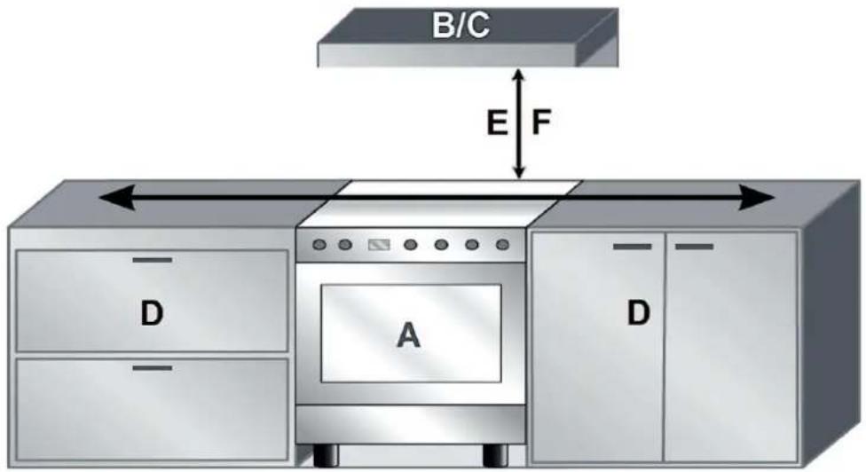
| A | GAS COOKER |
| B | WALL CABINET (if present) |
| C | EXTRACTOR HOOD (if present) |
| D | ADJACENT FURNITURE |
REQUIRED MINIMUM DISTANCES
| E | to an extractor hood: | ➢ min. 760 mm |
| F | to a wall cabinet: | ➢ min. 760 mm |
INSTALLATION OPTION C (APPLIANCE INTEGRATED IN A KITCHEN UNIT)
If the appliance is installed beside pieces of furniture that are higher than the appliance itself (top edge of the gas hob), a minimum distance of 50 mm must be maintained between the appliance and the furniture (s. fig. below).
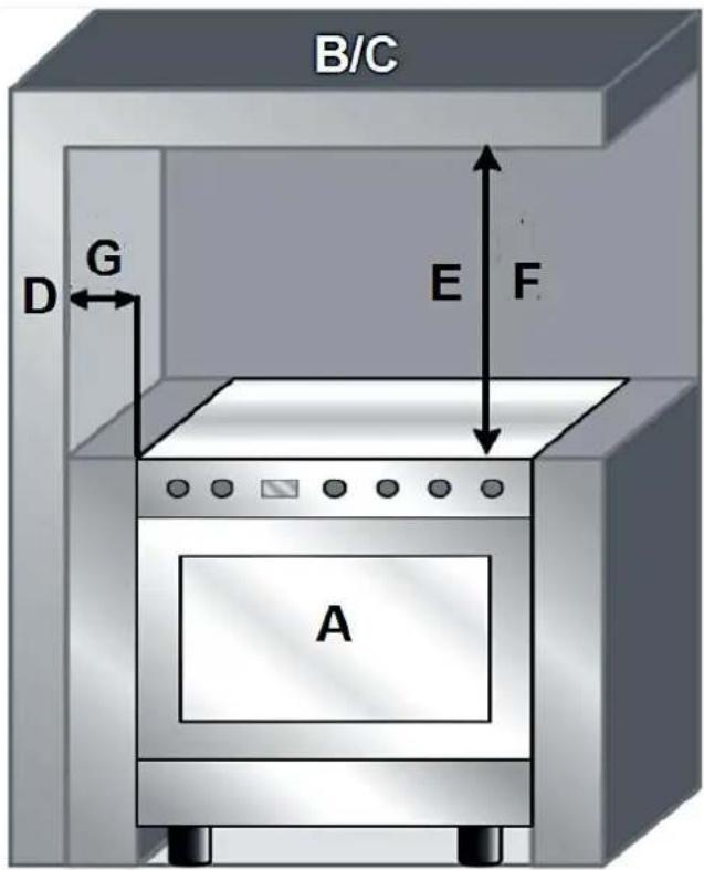
| A | GAS COOKER |
| B | WALL CABINET (if present) |
| C | EXTRACTOR HOOD (if present) |
| D | WALL / WALL OF A CABINET |
REQUIRED MINIMUM DISTANCES
| E | to an extractor hood: | ➢ min. 760 mm |
| F | to a wall cabinet: | ➢ min. 760 mm |
| G | to an adjacent wall / wall of a cabinet: | ➢ min. 50 mm |
2.3 Room ventilation
The appliance must be installed and operated in constantly ventilated rooms only. The appliance must not be installed in a bed sitting room with a volume of less than 20 m ^3 .
Sufficiently ventilated rooms are required for proper operation. Rooms, in which gas-operated appliances are installed and operated, must be supplied with at least that quantity of fresh air which is required to operate the appliance. When any other fuels burning appliances are operated in the same room, the exhaust requirements of these appliances must be included when calculating the required air vent.
The fresh air must flow through the openings of the outer walls directly. This opening / these openings should be performed in such a way, that it/they cannot be blocked neither from inside nor from outside.
So, you must provide openings for the supply of fresh air, which meet the following requirements:
a. free total cross-section of 6 cm^2 per kW with at least 100 cm^2 (these openings may be provided by enlarging the space between door and floor).
b. the openings must be in the lower section of an outer wall, preferably opposite the wall where the combustion products are discharged.
c. the openings must be placed in such a way that they cannot be blocked. If they are placed in an outer wall, they must be protected (along the outer perimeter of the wall) by a metal grid or similar objects.
If an electric fan for the product discharge is installed, the openings for the air exchange must have an air flow rate of at least 35 34 h per kW of installed capacity.
i Installation and maintenance must only be carried out by a qualified professional relevant to the current local and legal regulations.
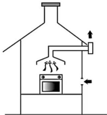
Gas cookers must discharge their combustion products by means of extractor hoods that are connected to smoke outlets or lead to the outside directly (s. fig. below). The required safety distance between the extractor hood and the gas cooker must be at least 760 mm.

natural_image
Diagram of a heating or cooling system with a microwave oven and airflow arrows (no text or labels)
natural_image
Diagram of a heating room with oven, air ducts, and airflow indicators (no text or labels)
2.4 Installation of the adapter feet
The appliance must stand in a stable and level position to ensure proper operation. The supplied adapter feet enable proper levelling and individual height adjustment relevant to the height of your kitchen furniture. We recommend the usage of the adapter feet to provide optimum stability of the appliance.
Depending on model: the adapter feet of the appliance must yet be installed.
HOW TO INSTALL THE ADAPTER FEET ^33
- The fixing bars (B) for the adapter feet are on both sides of the bottom of the appliance (A / s. fig. below).

| A | BOTTOM OF THE GAS COOKER |
| B | FIXING BAR (on both sides / 2 in total) |
- Screw the adapter feet (D) into the prepared openings properly (C / s. fig. below).

| B | FIXING BAR (on both sides / 2 in total) |
| C | TWO PREPARED OPENINGS incl. nuts (on both sides / 4 in total) |
| D | ADAPTER FEET (screwed in / 4 in total) |
HOW TO LEVEL THE APPLIANCE
- After the appliance has been connected to the mains and gas supply and is finally in the desired installation site, the appliance must be levelled.
The appliance must stand in a stable and level position to ensure proper operation. The supplied adapter feet enable proper levelling and individual height adjustment relevant to the height of your kitchen furniture.
The adapter feet must stand firmly on the ground so that the appliance does not wobble. Adjust the adapter feet accordingly. The firm contact of the adapter feet with the ground also ensures that the appliance does not vibrate or move unintentionally.
The possible height adjustment of the adapter feet is between 90 mm (adapter feet screwed in) and 120 mm (adapter feet screwed out).
When the appliance is not levelled, the door and the seals may not close properly.

natural_image
Technical diagram showing mechanical components with two upward arrows indicating motion or force direction (no text or symbols present)
2.5 Chain installation
For proper and safe operation, you must secure the appliance using the chain and threaded hook.
i Ensure that the hook is tightened properly and safely!

Fig. similar: modifications are possible.
| A | SAFETY HOOK |
| B | WALL |
| C | SAFETY CHAIN |
| D | approx. 750 mm |
2.6 Connection to the gas supply
⚠️ DANGER! The appliance must be connected to the gas supply by a qualified professional (gas fitter), Do not connect the appliance to the gas supply yourself.
DANGER! The appliance must be connected to the gas supply by a qualified professional (gas fitter), who is familiar with and adheres to the local requirements and supplementary regulations of your gas supplier.
⚠️ DANGER! Do not modify the gas supply. The connection must be carried out in accordance with the current local and legal regulations.
⚠️ DANGER! Germany as well as many other member countries of the European Union have very strict legal provisions on the energy supply of domestic appliances with bottled gas. If you want to use bottled gas, you must consult a qualified professional before; otherwise, you will not only endanger your life, but also the life of third-parties.
⚠ WARNING! Any damage caused by an appliance that is not connected to the gas supply properly is not subject to the guarantee!
You can install a gas socket. The installation of a gas socket must be carried out by a qualified professional (gas fitter) relevant to the current local and legal regulations.
INSTRUCTIONS FOR THE QUALIFIED PROFESSIONAL (GAS FITTER)
The appliance can be operated with natural gas or LPG (Liquefied Petroleum Gas). Do not use other types of gas.
Standard factory setting for operation mode: NATURAL GAS. Please refer to the chapter « TECHNICAL DATA » for the specific type of natural gas that is relevant for your appliance.
The appliance can be connected to the gas supply using a solid tube (copper), a suitable flexible rubber gas hose or a suitable flexible metal gas hose made of stainless steel.
If you use a gas hose for the connection to the gas supply, it must meet the current local and legal regulations.
GENERAL INSTRUCTIONS FOR THE CONNECTION TO THE GAS SUPPLY USING A RUBBER GAS HOSE
⚠ WARNING! The rubber gas hose must meet the current local and legal regulations.
⚠ WARNING! A connection with a rubber gas hose that complies with the applicable regulations is only permitted if the gas hose can be inspected along its entire length.
The gas connection with a suitable rubber gas hose must be carried out in such a way that the length of the gas hose does not exceed 1.50 metres. The rubber gas hose must not contact any movable part and must not pass any place in which it can be kinked or blocked.
The inner diameter of the rubber gas hose must be 8 mm for LPG and 13 mm for NATURAL GAS.
◆ Ensure that all of the following conditions are met:
a. the rubber gas hose must be fixed to the hose connection with a safety clamp that conforms to standards.
b. the rubber gas hose must not come into contact with hot walls etc. (max. 50 °C).
c. the rubber gas hose must not be under tension and must not have any tight bends or twists (s. fig. below).
d. the rubber gas hose must not come into contact with sharp objects or sharp corners.
e. if the rubber gas hose is not completely tight and gas leaks out, do not try to repair it, but replace it with a new gas hose.
f. ensure that the expiry date of the rubber gas hose has not expired (the expiry date is printed on the rubber gas hose itself).


1
GAS HOSE
2
POWER SUPPLY CABLE
2.6.1 Natural gas: connection to the gas supply using a rubber gas hose
INSTRUCTIONS FOR THE QUALIFIED PROFESSIONAL (GAS FITTER)
If you connect the appliance to a NATURAL GAS supply using a rubber gas hose, you must use a gas hose whose specifications comply with the regulations in force (ensure that the reference standard is stamped on the hose).
For the connection to the NATURAL GAS supply, the internal diameter of the rubber gas hose must be 13 mm.
i The length of the gas hose must not exceed 1.50 metres.
The connection to the NATURAL GAS supply using a rubber gas hose is only permitted if the gas hose complies with the applicable regulations and can be inspected along its entire length. The appliance must be free-standing, i.e. the rubber gas hose must not be covered by kitchen furniture etc. (even parts of the gas hose must not be covered).
1. Position the seal (C) between the hose connection (A) and the gas connection of the appliance (B): s. fig. below.
2. Then screw the hose connection (A) onto the gas connection of the appliance (B) carefully and tighten it: s. fig. below.
3. Push the rubber gas hose (D) onto the hose connection (A) and fasten it with a clamp (E): s. fig. below. The clamp must comply with the applicable standard.
4. Ensure that the rubber gas hose is installed properly.
5. Carry out a leak test (e.g. with soap solution, never with a flame).
HOW TO CONNECT THE APPLIANCE TO THE NATURAL GAS SUPPLY USING A RUBBER GAS HOSE

| A | HOSE CONNECTION |
| B | GAS CONNECTION OF THE APPLIANCE |
| C | SEAL |
| D | RUBBER GAS HOSE |
| E | CLAMP (according to standard) |
WARNING! Never forget to insert the seal!
⚠ WARNING! The tightening torque between connections containing a seal must not exceed 10 Nm.
WARNING! After installation, a leak test of the gas hose, gas hob and the complete installation must be carried out. Ensure, that the main connection does not exert any tension on the hob. The gas hose must not contact any movable part and must not pass any place in which it can be kinked or blocked.
⚠ WARNING! No tension force must be exerted on the connections!
2.6.2 LPG: connection to the gas supply using a rubber gas hose
⚠️ DANGER! The conversion to LPG must be carried out by a qualified professional (gas fitter) only. RISK OF EXPLOSION! RISK OF FIRE!
INSTRUCTIONS FOR THE QUALIFIED PROFESSIONAL (GAS FITTER)
There are rigorous legal regulations in Germany and many other members of the EU concerning the operation of domestic appliances with bottled gas.
If the appliance is supplied with bottled LPG, a pressure regulator which meets the current legal and municipal regulations must be installed. Ensure that the supply pressure corresponds to the values given in chapter 2.9.1. LPG: TABLE OF BURNERS AND BURNER-JETS CHARACTERISTICS.
If you convert the gas supply to LPG, you must replace the burner-jets for natural gas with suitable burner-jets for LPG (propane gas jets / included in the delivery): s. chapter 2.9 CONVERSION TO LPG SUPPLY: REPLACEMENT OF THE BURNER-JETS.
If you connect the appliance to an LPG supply using a rubber gas hose, you must use a gas hose whose specifications comply with the regulations in force (ensure that the reference standard is stamped on the hose). Use a standard rubber gas hose with a length of at least 1.40 metres for the connection between the appliance and the gas bottle. The length of the rubber gas hose must not exceed 1.50 metres.
For the connection to the LPG supply, the internal diameter of the rubber gas hose must be 8 mm.
The connection to the LPG supply using a rubber gas hose is only permitted if the gas hose complies with the applicable regulations and can be inspected along its entire length. The appliance must be free-standing, i.e. the rubber gas hose must not be covered by kitchen furniture etc. (even parts of the gas hose must not be covered).
HOW TO CONNECT THE APPLIANCE TO THE LPG SUPPLY USING A RUBBER GAS HOSE
- Position the seal (C) between the hose connection (A) and the gas connection of the appliance (B): s. fig. below.
-
Then screw the hose connection (A) onto the gas connection of the appliance (B) carefully and tighten it: s. fig. below.
-
Push the rubber gas hose (D) onto the hose connection (A) and fasten it with a clamp (E): s. fig. below. The clamp must comply with the applicable standard.
-
Ensure that the rubber gas hose is installed properly.
-
Carry out a leak test (e.g. with soap solution, never with a flame).
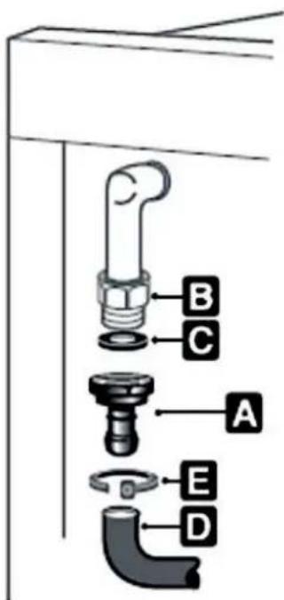
| A | HOSE CONNECTION |
| B | GAS CONNECTION OF THE APPLIANCE |
| C | SEAL |
| D | RUBBER GAS HOSE |
| E | CLAMP (according to standard) |

WARNING! Never forget to insert the seal!
⚠ WARNING! The tightening torque between connections containing a seal must not exceed 10 Nm.
WARNING! After installation, a leak test of the gas hose, gas hob and the complete installation must be carried out. Ensure, that the main connection does not exert any tension on the hob. The gas hose must not contact any movable part and must not pass any place in which it can be kinked or blocked.
⚠ WARNING! No tension force must be exerted on the connections!
⚠ WARNING! After converting to a gas other than the default one, the gas setting label attached to the appliance must be replaced with the label for the new gas.
2.6.3 Natural gas / LPG: connection to the gas supply using a steel gas hose
INSTRUCTIONS FOR THE QUALIFIED PROFESSIONAL (GAS FITTER)
For both types of gas (LPG or natural gas), a standard-compliant gas hose made of stainless steel can be used. This type of connection can be used both for « built-in » (e.g.: integrated in a kitchen unit) and for free-standing appliances.
Only use a steel gas hose that conforms to standards. The length of the steel gas hose must not exceed 2.00 metres.
If you want to connect the appliance to an LPG supply using a steel gas hose, please always follow and observe all relevant safety instructions and information regarding LPG in chapter 2.6.2.
HOW TO CONNECT THE APPLIANCE TO THE NATURAL GAS OR LPG SUPPLY USING A STEEL GAS HOSE
- Position the seal (C) between the thread of the steel gas hose (F) and the gas connection of the appliance ( 12 " / B): s. fig. below.
- Then screw the steel gas hose (F) onto the gas connection of the appliance (B) carefully and tighten it: s. fig. below.
- Ensure that the steel gas hose is installed properly.
- Carry out a leak test (e.g. with soap solution, never with a flame).
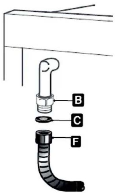
| B | GAS CONNECTION OF THE APPLIANCE |
| C | SEAL |
| F | STEEL GAS HOSE / THREAD |
WARNING! Never forget to insert the seal!
WARNING! The tightening torque between connections containing a seal must not exceed 10 Nm.
WARNING! After installation, a leak test of the gas hose, gas hob and the complete installation must be carried out. Ensure, that the main connection does not exert any tension on the hob. The gas hose must not contact any movable part and must not pass any place in which it can be kinked or blocked.
⚠ WARNING! No tension force must be exerted on the connections!
2.7 Electrical connection
⚠️ DANGER! Switch off the power supply (fuse box of your household power supply) before you connect the appliance to the mains. RISK OF ELECTRIC SHOCK!
⚠️ DANGER! All electrical work that may be necessary must be carried out by a qualified professional. Do not modify the energy and / or gas supply. The connection must be carried out in accordance with the current local and legal regulations. RISK OF ELECTRIC SHOCK!
⚠️ DANGER! The appliance must be grounded properly.
⚠️ DANGER! The technical data of your energy supplier must meet the data on the rating plate of the appliance.
⚠ WARNING! Do not use an extension cord, socket strips or a multiple socket. RISK OF FIRE!
⚠ WARNING! Connect the appliance to a properly grounded socket only. Use a safety socket to minimise any risk of electric shock.
⚠ WARNING! The power cord must not be trapped or kinked.
◆ Operate the appliance with 220 \~ 240 V AC / 50 Hz only.
The appliance is equipped with a power supply cable and a power plug (safety plug).
❖ Only use the power supply cable provided with the appliance.
- Your household power supply must meet the power consumption of the appliance.
When connecting do not use adapters, reducers and branching devices as they cause overheating. RISK OF FIRE!
Do not modify the plug provided with the appliance, if it will not fit the outlet, have a proper outlet installed by a qualified electrician (not covered by the guarantee).
When the power cord is damaged, it must be replaced by the manufacturer or an authorised aftersales service or a qualified professional only.
The power cord must not touch hot areas and its temperature must not exceed 75^ C.
When the socket is not accessible for the user after the installation of the appliance or a fixed electrical connection of the appliance is required, an all-pole disconnecting device must be incorporated during installation. Disconnecting devices are switches with a contact opening distance of at least 3 mm. These include LS-switches, fuses and protectors (EN 30335).
When installing the appliance, contact protection must be ensured.
If you are in doubt as to whether the appliance is connected to the mains properly, let the electrical connection be checked by a qualified electrician (not covered by the guarantee).
NOTICE! Any damages which are caused by an appliance that is not connected to the mains properly are not subject to the guarantee!
2.8 Natural gas: adjustment of the burner-jets to minimal-flame
INSTRUCTIONS FOR THE QUALIFIED PROFESSIONAL (GAS FITTER)
The minimal-flame of all burner-jets must be adjusted properly.
- Ignite a gas burner (s. chapter 4.2.5 IGNITION OF A GAS BURNER) and set it to the minimum level « ⬇ » (D) using the rotary knob (A). The mark on the rotary knob (A 1) must face the minimum level (D / s. fig. below).
To ignite a gas burner, turn the respective rotary knob to the minimum level (D) in anticlockwise direction only, otherwise you may damage the rotary knob.
- Then pull off the rotary knob (A).

chemical
Diagram showing molecular interaction between two circular structures with labeled components A1 and B, connected by a transformation arrow
Fig. similar: modifications are possible.
| A | ROTARY KNOB |
| A 1 | MARK OF THE ROTARY KNOB |
| B | POSITION OF THE GAS BURNER (cooking zone) |
| C | GAS BURNER « OFF » (no gas supply) |
| D | MINIMUM LEVEL (minimal-flame / minimum gas supply) |
| E | MAXIMUM LEVEL (maximum gas supply) |
- Then adjust the minimal-flame of the burner-jet using the adjusting screw (F) properly (s. fig. below). To adjust the minimal-flame, turn the adjusting screw using a flathead screwdriver until the smallest burner flame (minimal-flame) burns steadily and evenly.
Depending on model, the adjustment screw (F) is on the left above the rotary knob shaft or in the middle of the rotary knob shaft (s. fig. below).

Fig. similar: modifications are possible.
| F / F 1 | ADJUSTMENT SCREW (depending on model) |
| G | ROTARY KNOB SHAFT |
- Push the rotary knob (A) back onto the rotary knob shaft properly. The mark of the rotary knob (A 1) must face the minimum level (D / s. fig. below).

Fig. similar: modifications are possible.
| A | ROTARY KNOB |
| A 1 | MARK OF THE ROTARY KNOB |
| D | MINIMUM LEVEL (minimal-flame / minimum gas supply) |
- Check that the minimal-flame of the burner-jet is adjusted correctly and properly: the minimal-flame is adjusted correctly and properly when the flame does not go off when rapidly turning the rotary knob from maximum level (E) to minimum level (D): s. fig. below.

chemical
Diagram of a chemical reaction or electrochemical process involving droplets labeled E and D, with a control panel above showing circular components.
Fig. similar: modifications are possible.
| D | MINIMUM LEVEL (minimal-flame / minimum gas supply) |
| E | MAXIMUM LEVEL (maximum gas supply) |
- Repeat the adjustment and checking of the minimal-flame on all burners.
NOTICE! If any burner-jet has been replaced, the professional (gas fitter) must mark this burner-jet.
2.8.1 Natural gas: table of burners and burner-jets characteristics
i Please refer to the chapter « TECHNICAL DATA » for the specific type of natural gas that is relevant for your appliance.
| TYPE OF NATURAL GAS | HI* / Hs** | SMALL BURNER | MEDIUM BURNER | BIG BURNER | TRIPLE BURNER (WOK) |
|
| G20-20 mbar | Hi | 0.81 kW | 1.49 kW | 2.52 kW | 2.97 kW |
| Hs | 0.90 kW | 1.65 kW | 2.80 kW | 3.30 kW |
| JET (injector) | ∅ in mm | 0.70 | 0.95 | 1.20 | 0.85 |
|
| G20-25 mbar | Hi | 0.86 kW | 1.49 kW | 2.52 kW | 2.88 kW |
| Hs | 0.95 kW | 1.65 kW | 2.80 kW | 3.20 kW |
| JET (injector) | ∅ in mm | 0.70 | 0.92 | 1.15 | 1.35 |
| TYPE OF NATURAL GAS | Hi* / Hs** | SMALL BURNER | MEDIUM BURNER | BIG BURNER | TRIPLE BURNER (WOK) |
|
| G25-25 mbar | Hi | 0.81 kW | 1.49 kW | 2.52 kW | 2.88 kW |
| Hs | 0.90 kW | 1.65 kW | 2.80 kW | 3.20 kW |
| JET (injector) | ∅ in mm | 0.70 | 0.95 | 1.20 | 1.35 |
|
| * | Hi | HEATING VALUE |
| ** | Hs | COMBUSTION VALUE |
2.9 Conversion to LPG supply: replacement of the burner-jets
⚠️ DANGER! The conversion of the gas supply to LPG (and back to natural gas if necessary) must be carried out by a qualified professional (gas fitter). RISK OF EXPLOSION! RISK OF FIRE!!
INSTRUCTIONS FOR THE QUALIFIED PROFESSIONAL (GAS FITTER)
There are rigorous legal regulations in Germany and many other members of the EU concerning the operation of domestic appliances with bottled gas.
If the appliance is supplied with bottled LPG, a pressure regulator which meets the current legal and municipal regulations must be installed. Ensure that the supply pressure corresponds to the values given in chapter 2.9.1. LPG: TABLE OF BURNERS AND BURNER-JETS CHARACTERISTICS.
The gas supply of the appliance can be converted to LPG provided that the correct burner-jets are installed and the gas flow rate is adjusted properly. If you convert the gas supply to LPG, you must replace the burner-jets for natural gas with suitable burner-jets for LPG (propane gas jets / included in the delivery): s. chapter 2.9 CONVERSION TO LPG SUPPLY: REPLACEMENT OF THE BURNER-JETS.
⚠ WARNING! After converting to a gas other than the default one, the gas setting label (e.g. natural gas) attached to the appliance must be replaced with the label for the new gas (e.g. LPG).
NOTICE! If any burner-jet has been replaced, the professional (gas fitter) must mark this burner-jet.
HOW TO REPLACE THE BURNER-JETS FOR THE OPERATION WITH LPG.
-
Remove the pot grid(s).
-
Remove the burner caps (A) and pull out the burner crowns (B).
-
Unscrew the burner-jets using a socket spanner (7 mm / D): s. fig. below.
Store the removed burner-jets for natural gas in a dry and safe place for a possible future use.

Fig. similar: modifications are possible.
| A | BURNER CAP |
| B | BURNER CROWN |
| C | BURNER-JET (for natural gas) |
| D | SOCKET SPANNER (7 MM) |
-
Replace the removed burner-jets for natural gas with the burner-jets for LPG (propane gas) supplied, according to the table of burners and burner-jets characteristics: s. chapter 2.9.1 LPG: TABLE OF BURNERS AND BURNER-JETS CHARACTERISTICS.
-
Tighten the burner-jets for LPG (propane gas) carefully using a suitable socket spanner (s. fig. below).

Fig. similar: modifications are possible.
| D | SOCKET SPANNER |
| E | BURNER-JET (for LPG / propane gas) |
- The gas burners do not need a primary air regulation.
- Replace the gas burners in the correct position and reinstall the burner crowns, burner caps and pot grids properly.
- Adjust the burner-jets for LPG to minimal-flame (minimum level): s. chapter 2.9.2 LPG: ADJUSTMENT OF THE BURNER-JETS TO MINIMAL-FLAME.
2.9.1 LPG: table of burners and burner-jets characteristics
i Please refer to the chapter « TECHNICAL DATA » for the specific type of LPG that is relevant for your appliance.
| TYPE OF LPG | Hi* / Hs** | SMALL BURNER | MEDIUM BURNER | BIG BURNER | TRIPLE BURNER (WOK) | |
| |
| G30-30 mbar | Hi | 0.81 kW | 1.49 kW | 2.52 kW | 2.79 kW | |
| Hs | 0.90 kW | 1.65 kW | 2.80 kW | 3.10 kW | |
| JET (injector) | ∅ in mm | 0.50 | 0.65 | 0.85 | 0.92 | |
| |
| G31-37 mbar | Hi | 0.81 kW | 1.49 kW | 2.52 kW | 2.79 kW | |
| Hs | 0.90 kW | 1.65 kW | 2.80 kW | 3.10 kW | |
| JET (injector) | ∅ in mm | 0.50 | 0.65 | 0.85 | 0.92 | |
|
| G30-37 mbar | Hi | 0.86 kW | 1.58 kW | 2.52 kW | 2.97 kW | |
| Hs | 0.95 kW | 1.75 kW | 2.80 kW | 3.30 kW | |
| JET (injector) | ∅ in mm | 0.50 | 0.65 | 0.80 | 0.90 | |
| |
| * | Hi | HEATING VALUE | |
| ** | Hs | COMBUSTION VALUE | |
2.9.2 LPG: adjustment of the burner-jets to minimal-flame
INSTRUCTIONS FOR THE QUALIFIED PROFESSIONAL (GAS FITTER)
The minimal-flame must be adjusted properly for all burner-jets even when the appliance is supplied with LPG.
- Ignite a gas burner (s. chapter 4.2.5 IGNITION OF A GAS BURNER) and set it to the minimum level « ⬇ » (D) using the rotary knob (A). The mark on the rotary knob (A 1) must face the minimum level (D / s. fig. below).
To ignite a gas burner, turn the respective rotary knob to the minimum level (D) in anticlockwise direction only, otherwise you may damage the rotary knob.
- Then pull off the rotary knob (A).

chemical
Diagram showing molecular interaction between two circular structures labeled A1 and B, with arrows indicating transformation or reaction.
Fig. similar: modifications are possible.
| A | ROTARY KNOB |
| A 1 | MARK OF THE ROTARY KNOB |
| B | POSITION OF THE GAS BURNER (cooking zone) |
| C | GAS BURNER « OFF » (no gas supply) |
| D | MINIMUM LEVEL (minimal-flame / minimum gas supply) |
| E | MAXIMUM LEVEL (maximum gas supply) |
- Then adjust the minimal-flame of the burner-jet properly. To adjust the minimal-flame of a burner-jet with LPG supply, the relevant screw of the gas burner must be completely tightened in clockwise direction (one whole turn / 360°) using a flat-head screwdriver (s. fig. below).

natural_image
Close-up of a mechanical assembly with a red circular arrow indicating rotational motion (no text or symbols visible)
Fig. similar: modifications are possible.
- Push the rotary knob (A) back onto the rotary knob shaft properly. The mark of the rotary knob (A 1) must face the minimum level (D / s. fig. below).
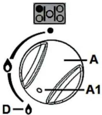
Fig. similar: modifications are possible.
| A | ROTARY KNOB |
| A 1 | MARK OF THE ROTARY KNOB |
| D | MINIMUM LEVEL (minimal-flame / minimum gas supply) |
- Check that the minimal-flame of the burner-jet is adjusted correctly and properly: the minimal-flame is adjusted correctly and properly when the flame does not go off when rapidly turning the rotary knob from maximum level (E) to minimum level (D): s. fig. below.

chemical
Diagram of a chemical reaction or electrochemical process involving E and D components with electron flow arrows
Fig. similar: modifications are possible.
| D | MINIMUM LEVEL (minimal-flame / minimum gas supply) |
| E | MAXIMUM LEVEL (maximum gas supply) |
- Repeat the adjustment and checking of the minimal-flame on all burners.
NOTICE! If any burner-jet has been replaced, the professional (gas fitter) must mark this burner-jet.
3.1 General view of the appliance
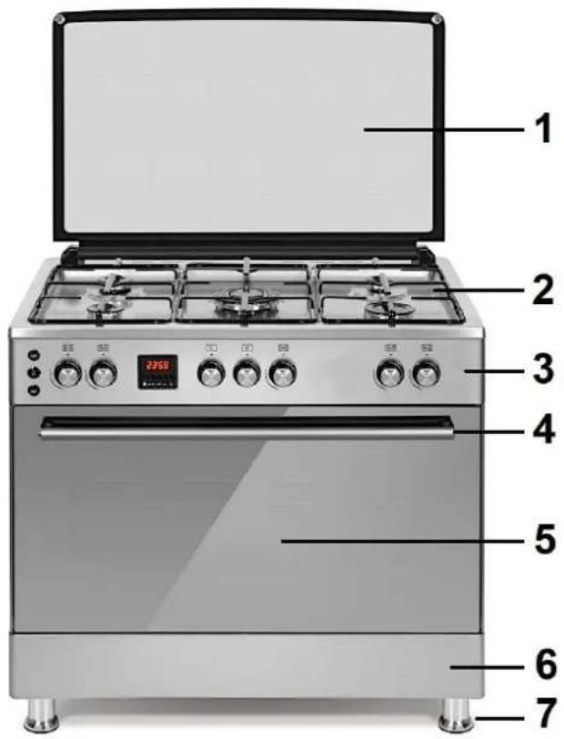
Fig. similar: modifications are possible.
| 1 | GLASS COVER OF THE GAS HOB |
| 2 | GAS HOB (s. chapter 3.2 VIEW OF THE GAS HOB) |
| 3 | CONTROL PANEL (s. chapter 3.4 VIEW OF THE CONTROL PANEL: ROTARY KNOBS AND OPERATING BUTTONS) |
| 4 | HANDLE OF THE OVEN DOOR |
| 5 | DOOR OF THE OVEN |
| 6 | DRAWER |
| 7 | ADJUSTABLE ADAPTER FEET |
3.2 View of the gas hob

Fig. similar: modifications are possible.
| 8 | STANDARD BURNER |
| 9 | RAPID BURNER |
| 10 | SMALL BURNER |
| 11 | TRIPLE BURNER |
| 12 | POT GRID |
3.2.1 Diameters of the gas burners
| GAS BURNER | DIAMETER |
| SMALL BURNER (small size gas burner) | 55.00 mm ∅ |
| STANDARD BURNER (medium size gas burner) | 75.00 mm ∅ |
| RAPID BURNER (large size gas burner) | 100.00 mm ∅ |
| TRIPLE BURNER (Wok burner) | 134.00 mm ∅ |
3.3 View of the electric oven

Fig. similar: modifications are possible.
| 13 | HANDLE OF THE OVEN DOOR |
| 14 | DOOR OF THE OVEN |
| 15 | DOOR HINGES OF THE OVEN |
| 16 | INTERIOR OF THE OVEN |
| 17 | SIDE RACKS (on both sides) ^34 |
| 18 | FAN (fan / hot air ^35 ) |
| 19 | INTERNAL LIGHT |
3.3.1 Accessories
Depending on model, a grilling grate, a drip tray (oven pan) and / or a baking tray (deep oven pan) are included in the scope of delivery.
i Clean the supplied accessories with warm soapy water and a soft cloth before you use the appliance for the first time.
When the slide-in elements (e.g.: grilling grate / drip tray / baking tray) become hot, they may deform. As soon as the slide-in elements have cooled, they return to their original shape. The functionality is not affected thereby.
NOTICE! Always ensure that the slide-in elements (e.g.: grilling grate / drip tray / baking tray) are fully inserted into the oven, so they do not collide with the oven door when closing it
NOTICE! If you grill on the grilling grate directly, always use the drip tray or the baking tray to catch the dripping grease of the food to be grilled.
GRILLING GRATE
The grilling grate is suitable for the grilling, roasting and baking of food; it is also suitable for the cooking of food in casseroles and for the baking of cakes in cake moulds.

natural_image
Simple line drawing of a rectangular grid structure with vertical lines (no text or symbols)
DRIP TRAY (OVEN PAN)
The drip tray (oven pan) is suitable for the baking of cakes and biscuits and for the preparing of frozen meals and large roasts.
If you grill on the grilling grate directly, the drip tray (oven pan) must also be used to catch the dripping grease of the food to be grilled.

natural_image
Isometric line drawing of a rectangular electronic device with internal components (no text or symbols)
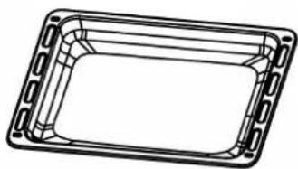
BAKING TRAY (DEEP OVEN PAN) ^36
The baking tray (deep oven pan) is suitable for the baking of cakes and biscuits and for the preparing of large roasts, etc.
If you grill on the grilling grate directly, the baking tray as well as the drip tray is suitable to catch the dripping grease of the food to be grilled.
natural_image
Line drawing of a rectangular plastic tray with side brackets and cutouts (no text or symbols)
SIDE RACKS
◆ Depending on model: the side racks are integrated or removable.
You can insert the grilling grate, the drip tray and the baking tray in the different insertion heights (up to four ^37 ) of the side racks. According to your needs, you can bake, roast or grill at different insertion heights.
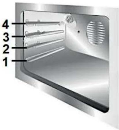
Fig. similar: modifications are possible.

Fig. similar: modifications are possible.
| ROTARY KNOBS |
| A |  | ROTARY KNOB TO CONTROLTHE FRONT LEFT GAS BURNER➢ Turn the rotary knob in anticlockwise direction only to ignite this gas burner.➢ See also chapter 4.2.5 IGNITION OF A GAS BURNER. |
| B |  | ROTARY KNOB TO CONTROLTHE REAR LEFT GAS BURNER➢ Turn the rotary knob in anticlockwise direction only to ignite this gas burner. |
| C |  | ROTARY KNOB TO CONTROLTHE MIDDLE GAS BURNER➢ Turn the rotary knob in anticlockwise direction only to ignite this gas burner. |
| D |  | ROTARY KNOB TO CONTROLTHE REAR RIGHT GAS BURNER➢ Turn the rotary knob in anticlockwise direction only to ignite this gas burner. |
| E |  | ROTARY KNOB TO CONTROLTHE FRONT RIGHT GAS BURNER➢ Turn the rotary knob in anticlockwise direction only to ignite this gas burner. |
| F |  | ROTARY KNOB « OVEN TEMPERATURE »➢ Rotary knob for the selection of the OVEN TEMPERATURE.➢ The temperature of the oven can be adjusted from 50 °C to 260 °C. |
| G |  | ROTARY KNOB « OVEN FUNCTIONS »➢ Rotary knob for the selection of the OVEN FUNCTIONS.➢ This rotary knob selects the desired cooking function.➢ Seven different oven functions are selectable (s. chapter 4.5 OVEN FUNCTIONS). |
| H |  | DISPLAY: INDICATORS AND OPERATING BUTTONS➢ Description: s. chapter 3.5. |
| OPERATING BUTTONS |
| 1 |  | «INTERNAL LIGHT» - BUTTON38➢ Use this button to switch on / off the internal light of the oven. |
| 2 |  | «IGNITE BURNER» - BUTTON➢ To ignite the desired GAS BURNER, you must set the corresponding rotary knob to the minimum level and press this button simultaneously.➢ See also chapter 4.2.5 IGNITION OF A GAS BURNER. |
The display indicates the system time or the set current time.
You can programme the oven (e.g.: setting of the time, setting of the timer, etc.) using the operating buttons of the display (see also chapter 4.3 HOW TO USE THE OVEN et seq. and chapter 4.4 PROGRAMMING OF THE OVEN et seq.).
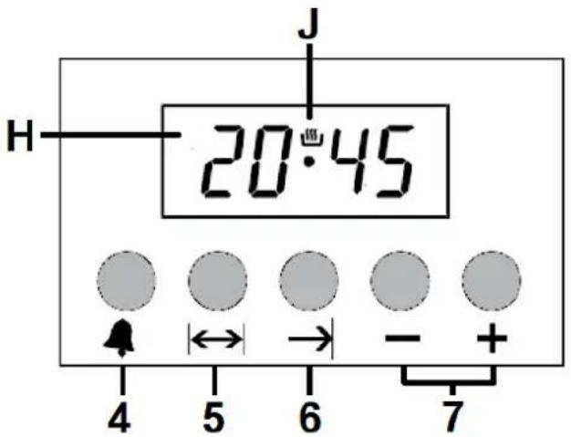
Fig. similar: modifications are possible.
INDICATORS
| H |  | LED DISPLAY➢ The LED display indicates the system time or the se current time as well as the operational status indicator of the selected function (timer, duration of the cooking baking time, etc.). |
| J |  | OPERATIONAL STATUS INDICATOR➢ Oven on standby (STANDBY MODE)➢ In order to use the oven, this operational status indicator must be lit on the LED display (H). |
OPERATING BUTTONS
| 4 |  | «TIMER»-BUTTON➢Use this button to set the timer.➢See chapter 4.4 PROGRAMMING OF THE OVEN et seq. |
| 5 |  | «DURATION OF THE COOKING / BAKINGTIME»-BUTTON➢Use this button to programme the desired DURATION of the cooking, baking time.➢See chapter 4.4 PROGRAMMING OF THE OVEN et seq. |
| 6 |  | «END OF THE COOKING / BAKING TIME»-BUTTON➢Use this button to programme the desired END of the cooking, baking time.➢See chapter 4.4 PROGRAMMING OF THE OVEN et seq. |
| 7 |  | «+/-»-BUTTONS➢Button for the setting of the TIME (decrease / increase).➢Button for the setting of the TIMER (decrease / increase). |
i Read the complete instruction manual before you operate the appliance for the first time. Strictly observe the safety instructions!
i Remove the complete protective film!
4.1 Before the first use
4.1.1 Gas hob
- Clean the surface of the gas hob (look at chap. CLEANING AND MAINTENANCE).
Adjust the minimal-flame on all burner-jets (for natural gas, s. chapter 2.8 Natural gas: ADJUSTMENT OF THE BURNER-JETS TO MINIMAL-FLAME; for LPG, s. chapter 2.9.2 LPG: ADJUSTMENT OF THE BURNER-JETS TO MINIMAL-FLAME).
4.1.2 Oven
i Manufacturing residues or oil having which have remained in the cooking compartment or on the heating element may cause some odours and smoke emission. These are normal operational parameters, which will disappear after several uses. Heat the appliance (empty and closed) before you use it for the first time for cooking to remove the residues and the resulting odours
HOW TO HEAT THE OVEN
- Remove all packaging material.
- Clean the oven inside from all protective agents.
- Take out the supplied accessories and clean them with warm water and washing-up liquid.
- Switch on the room ventilation or open a window.
- Let the oven operate for 30 minutes (top and bottom heat or similar oven function ^39 / 250 °C / s. chapter 4.3 HOW TO USE THE OVEN et seq.). A little bit of smoke and odour may be generated for approx. 15 minutes. This is normal. They are generated by the substance, that protects your appliance against damage caused by the shipment from the manufacturer's works.
NOTICE! Clean the oven with warm water and washing-up liquid only.
NOTICE! Ensure that the complete packaging material (inside and outside of the appliance) has been removed before initial operation.
4.1.3 Cleaning of the accessories
- Clean the accessories which are included in delivery using warm soapy water and a soft cloth before you use the appliance for the first time.
4.2 How to use the gas hob
4.2.1 Preparations
Before igniting a gas burner, always check whether the burner crown (2) is placed on the respective gas burner properly. The openings (a / arrows) in the burner crown (2) must be aligned with the ignition electrode (5) and the thermocouple (6) correctly (s. fig. below).

Fig. similar: modifications are possible.
| 1 | BURNER CAP |
| 2 | BURNER CROWN |
| 3 | BURNER PLATE |
| 4 | BURNER-JET |
| 5 | IGNITION ELECTRODE |
| 6 | THERMOCOUPLE ^40 |
Please check before each use that the burner caps are placed on the burner crowns exactly (s. fig. below); otherwise, the appliance can be damaged.

RIGHT

WRONG
⚠ WARNING! Never close the glass cover of the appliance while the gas hob and / or the electric oven are in operation.
⚠ WARNING! Never touch the gas burners and / or the pot grids while they are still hot. RISK OF BURNS!
NOTICE! Please check before each use that the burner caps are placed on the burner crowns exactly; otherwise, the appliance can be damaged.
4.2.2 Suitable cookware
i Only use cookware that is suitable for the use on a gas hob.
Use proper cookware with a flat bottom which meets the diameter of the gas burner for optimum efficiency of the gas burners.
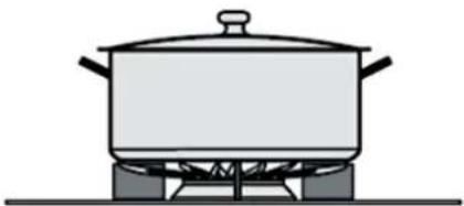
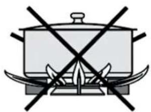
Do not use cookware the diameter of which is too small; otherwise, the flame will spread around the cookware and overheat the handle (s. fig. below). RISK OF BURNS!
natural_image
Simple line drawing of a cooking pot with crossed black lines indicating resistance or prohibition (no text or symbols)

natural_image
Simple line drawing of a cooking pot on a gas stove (no text or symbols)
The cookware must stand on the pot grid safely and evenly (s. fig. below).

natural_image
Four black-and-white icons showing a cooking pot with crossed x marks, no text or symbols present.
MINIMUM AND MAXIMUM DIAMETERS OF THE COOKWARE
The base of the cookware should have a minimum diameter and a maximum diameter according to the gas burner used (see table below). The gas burner efficiency cannot be used optimally if you use cookware that deviates from the recommended diameters for the respective gas burner.

Fig. similar: modifications are possible.
| 8 | STANDARD BURNER (medium size gas burner) |
| 9 | RAPID BURNER (large size gas burner) |
| 10 | SMALL BURNER (small size gas burner) |
| 11 | TRIPLE BURNER (Wok burner) |
| GAS BURNER | MINIMUM DIAMETER OF THE COOKWARE | MAXIMUM DIAMETER OF THE COOKWARE |
| STANDARD BURNER | 160 mm | 240 mm |
| RAPID BURNER | 180 mm | 260 mm |
| SMALL BURNER | 120 mm | 140 mm |
| TRIPLE BURNER | 200 mm | 300 mm |
4.2.3 Rotary knobs of the gas burners
flowchart
graph TD
    A["A"] --> B["B"]
    B --> C["C"]
    C --> D["D"]
    D --> E["E"]
    E --> A1["A1"]
    style A fill:#f9f,stroke:#333
    style B fill:#ccf,stroke:#333
    style C fill:#cfc,stroke:#333
    style D fill:#fcc,stroke:#333
    style E fill:#cff,stroke:#333
Fig. similar: modifications are possible.
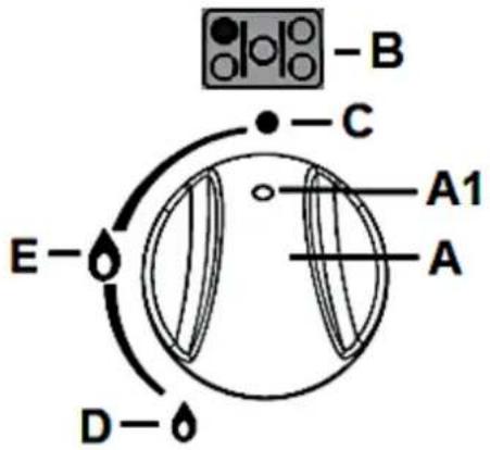
| A | ROTARY KNOB |
| A 1 | MARK OF THE ROTARY KNOB |
| B | POSITION OF THE GAS BURNER (cooking zone) |
| C | GAS BURNER « OFF » (no gas supply) |
| D | MINIMUM LEVEL (minimal-flame / minimum gas supply) |
| E | MAXIMUM LEVEL (maximum gas supply) |
| FLAME SIZE (= POWER SETTING):SETTING RANGE OF THE ROTARY KNOBS |
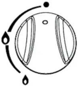 |  |
| OFF | MAXIMUM LEVEL(maximum-flame) |

natural_image
Simple circular diagram with two petal-like shapes and curved arrows indicating rotation or movement (no text or symbols)
MINIMUM LEVEL
(minimal-flame)

natural_image
Simple circular diagram with arrows and droplet symbols, no text or labels present
ADJUSTMENT RANGE BETWEEN
MIN. - MAX.
Fig. similar: modifications are possible.
The setting range of the rotary knobs is between position MAX. « 🔍 » and position MIN. « 🔍 ». The flame size (= power setting) can be regulated within this range.
The rotary knobs must never be set between position OFF « ● » and position MAX. « 🔍 ». The flame size (= power setting) cannot be regulated within this range.
To ignite a gas burner, turn the respective rotary knob to the minimum level in anticlockwise direction only, otherwise you may damage the rotary knob (see also chapter 4.2.5 IGNITION OF A GAS BURNER).
After cooking, turn the corresponding ROTARY KNOB to position OFF « ● » immediately to switch off the respective gas burner.
4.2.4 General operation of the gas hob
- Put a cookware directly onto the pot grid of a gas burner. Always keep the bottom of the cookware as well as the pot grid clean and dry.
- Ignite the gas burner (s. chapter 4.2.5 IGNITION OF A GAS BURNER). Turn the corresponding rotary knob with its mark between the positions MAX. « » and MIN. « » to set the desired flame size (= power setting).
- After cooking, turn the corresponding rotary knob to position OFF « ● » immediately to switch off the respective gas burner.
- Do not close the glass cover until all burners, pot grids etc. have cooled down completely.
⚠ WARNING! Never close the glass cover of the appliance while the gas hob and / or the electric oven are in operation.
⚠ WARNING! Never touch the gas burners and / or the pot grids while they are still hot. RISK OF BURNS!
4.2.5 Ignition of a gas burner
- Your appliance is equipped with an ELECTRONIC IGNITION DEVICE.
An improperly ignited gas burner can cause serious injury to persons or animals or damage to your property. The manufacturer cannot be held responsible for such injury or damage.
⚠ WARNING! Any damage caused by an improperly ignited gas burner is not subject to the guarantee!
Fig. similar: modifications are possible.
-
The gas burner ignites electronically and the flame should burn burns steadily and evenly at the minimum level.
-
You can now use the corresponding rotary knob to set the desired flame size (= power setting) of the gas burner: turn the rotary knob to the minimum level, to the maximum level or you can regulate the flame size within the setting range between the minimum and maximum level (see also chapter 4.2.3 ROTARY KNOBS OF THE GAS BURNERS).
-
After cooking, turn the corresponding rotary knob to position OFF « ● » immediately to switch off the respective gas burner.
If the burner flame does not ignite, return the rotary knob to position OFF « ● » and repeat the procedure.
The ignition device must not be operated for more than 15 seconds! If the burner has not ignited after 15 seconds, stop the ignition process and return the rotary knob of the corresponding gas burner to position OFF « ● ». Open the room door or a window and wait at least 60 seconds before you carry out further ignition processes.
If the burner flame goes out unintentionally, return the rotary knob to position OFF « ● ». Do not carry out any ignition process for at least 60 seconds.
If the burner flame does not ignite even after several attempts, check the proper arrangement of the burner components (s. chapter 4.2.1 PREPARATIONS).
In the event of a power failure or ignition failure, you can use a commercially available gas lighter or an extra-long match to ignite the burner flame. In such a case, be especially careful. RISK OF BURNS!
⚠ WARNING! In such a case, do not use a normal lighter or a normal match to ignite the burner flame. RISK OF BURNS!
IMPORTANT NOTES: FOR MODELS WITH THERMOCOUPLE ONLY!
Models with a thermocouple ^41 : the ignition button must be kept pressed for a few seconds after igniting the burner to give the thermocouple time to heat up. The burner may go out when the ignition button is released: in this case, the thermocouple has not heated up sufficiently. Wait a few moments and repeat the process by pressing the ignition button for a longer time. This is not necessary for burners that are not equipped with a thermocouple.
4.2.6 Ignition safety device
Models with thermocouple ^42 : in the case of an unintentional extinguishing of a burner flame, a safety device is triggered which interrupts the gas supply, even if the gas tap is open. In this case, turn the rotary knob back to position OFF « ● ». Wait at least 60 seconds before you try to ignite the burner again.
4.3 How to use the electric oven
⚠ WARNING! The accessible parts of the appliance become hot during operation, so keep children away from the operating appliance. Touching the appliance while it is operating can cause serious burns.
⚠️ CAUTION! The interior parts of the appliance become extremely hot. Do not touch any parts inside the appliance if you handle your cookware. RISK OF BURNS!
⚠️ CAUTION! Be careful if you open the door. Do not get in contact with the hot parts of the oven or the steam, which will escape the oven. RISK OF BURNS! RISK OF SCALDING!
⚠️ CAUTION! Cooking utensils may become hot because of the heat transferred by the heated food. Potholders or oven gloves may be needed to handle such utensils.
⚠️ CAUTION! Always use oven gloves.
NOTICE! Use suitable ovenware only.
i Proper positioning of the trays is mandatory for safe operation of the appliance. Otherwise, hot food or cookware can slide off the trays when removing them.

natural_image
Illustration of a simple oven with a rack inside, showing internal structure (no text or symbols)
Fig. similar.
AFTER THE CONNECTION OF THE APPLIANCE TO THE MAINS
When you connect the appliance to the mains for the first time, the display indicates « 0:00 » and the indicator « A » flashes. You can now set the current time / system time (s. chapter 4.3.3 SETTING OF THE TIME / SYSTEM TIME). You cannot use the timer and the automatic cooking and baking functions of the oven until you have set the current time / system time.
Before you can use the oven properly, you must set the current time / system time.
4.3.1 General operation of the oven
The oven can be warmed up using the bottom and top heaters.
The operation of the oven is controlled by the ROTARY KNOB for the selection of the OVEN FUNCTIONS (G / s. chapter 3.4 VIEW OF THE CONTROL PANEL: ROTARY KNOBS AND OPERATING BUTTONS). Seven different oven functions are selectable (s. chapter 4.5 OVEN FUNCTIONS). To set a function you should turn the knob to the desired position.
To select an oven temperature, use the ROTARY KNOB for the selection of the OVEN TEMPERATURE (F / s. chapter 3.4 VIEW OF THE CONTROL PANEL: ROTARY KNOBS AND OPERATING BUTTONS) to set the desired oven temperature. You can select an oven temperature between of 50 °C and 260 °C (turn in clockwise direction only).
To switch off the oven completely, you must turn both the rotary knob for the selection of the oven functions and the rotary knob for the selection of the oven temperature to position OFF « ● » (s. fig. below).
To switch on the oven, you must set an oven function and an oven temperature. If you only select an oven function, the oven does not switch on.
i The appliance is equipped with a 24-hour display.
| ROTARY KNOB:OVEN FUNCTIONS | ROTARY KNOB:OVEN TEMPERATURES |
 | 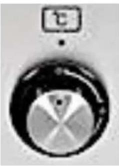 |
Fig. similar: modifications are possible.
NOTICE! To set an oven temperature, turn the rotary knob for the selection of the oven temperature in clockwise direction only. Otherwise, you may damage the rotary knob. After the cooking / baking process is finished, you can turn the rotary knob back to position OFF « ● » in anticlockwise direction.
OPERATIONAL STATUS INDICATORS OF THE OVEN ^43
The red light ^44 indicates that the oven is heating.
When the red light goes off the oven has reached the set temperature.
If a recipe recommends to place dishes in a warmed-up oven, place the dishes in the oven after the red light has gone off for the first time.
During a cooking / baking process, the red light of the oven will go off and on temporarily to maintain the set temperature.
4.3.2 Standby mode
In STANDBY MODE, the display indicates the system time or the set current time (s. fig. below).
To operate the oven, the operational status indicator « OVEN ON STANDBY » (standby mode) must be lit on the LED display (s. fig. below).
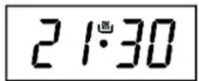
If the display indicates « A » (flashing) instead of « OVEN ON STANDBY », you must first set the current time / system time (s. chapter 4.3.3 SETTING OF THE TIME / SYSTEM TIME). You cannot use the timer and the automatic cooking and baking functions of the oven until you have set the current time / system time.
4.3.3 Setting of the time / system time
Before you can use the oven properly, you must set the current time / system time. You cannot use the timer and the automatic cooking and baking functions of the oven until you have set the current time / system time.
i Please note that the appliance is equipped with a 24-hour display. E.g.: if you want to set the time « 1.00 p.m. », you must set the display to 13.00 o'clock, etc.
HOW TO SET THE TIME / SYSTEM TIME
-
When you connect the appliance to the mains for the first time, the display indicates «0:00» and the indicator «A» flashes. You can now set the current time / system time.
-
Press the buttons « DURATION OF THE COOKING / BAKING TIME |↔| » and « END OF THE COOKING / BAKING TIME →» simultaneously to enter the time setting mode (s. fig. below).
-
The display indicates « 0:00 » and the decimal point of the time flashes: « ⚙ » (s. fig. below).
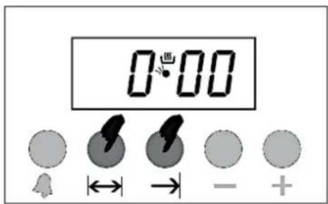
- Set the correct time of day within 5 seconds by repeatedly pressing the «+/-» - BUTTONS (e.g.: 21:30 / s. fig. below).
-
If the correct time is displayed (24-h display), wait a few seconds.
-
After approx. 5 seconds, the set time is saved and the decimal point of the time is on permanently: « • » (s. fig. below). The display indicates the set current time (e.g.: 21:30).

4.4 Programming of the oven
WARNING! The appliance must not leave unattended during cooking.
4.4.1 Timer
The TIMER serves as a timepiece and counts down the set time (countdown time).
The maximum settable countdown time is 23 hours and 59 minutes.
HOW TO USE THE TIMER (HOB GUARD)
- The oven must be in STANDBY MODE. In STANDBY MODE, the LED display indicates the current time / system time (e.g.: 21:30 / s. fig. below). The operational status indicator « OVEN ON STANDBY » must be lit on the LED display: « »(s. fig. below).
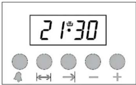
-
Press the « TIMER 🔊 » - BUTTON once to enter the timer setting mode (s. fig. below).
-
The display indicates « 0:00 » and the operational status indicator of the timer flashes: « 2 » (s. fig. below).

- Set the desired countdown time using the « +/ - » - BUTTONS (e.g.: 5 minutes / s. fig. below).

-
If the desired countdown time is displayed, wait a few seconds. After approx. 5 seconds, the set time is saved and the display indicates the current time / system time again (s. fig. below).
-
The operational status indicator of the timer is on permanently: « 4 » (s. fig. below). The setting is saved.
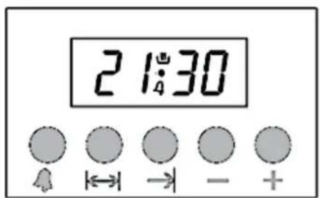
-
The countdown starts immediately.
-
If the countdown time has elapsed, an acoustic signal sounds and the operational status indicator of the timer flashes again: « 2» (s. fig. below).

- Press the « TIMER 🔊 » - BUTTON to witch off the acoustic signal. The operational status indicator of the timer goes off (s. fig. below).

To switch off the oven completely, you must turn both the rotary knob for the selection of the oven functions and the rotary knob for the selection of the oven temperature to position OFF « ● » (s. fig. below).
⚠ WARNING! When using the timer in countdown mode, the oven is not switched off automatically after the selected period of time has elapsed.
HOW TO CANCEL THE PROGRAMMING
You can cancel the programming at any time.
➢ Press the buttons « DURATION OF THE COOKING / BAKING TIME |↔| » and « END OF THE COOKING / BAKING TIME → | » once simultaneously. The oven returns to standby mode after a few seconds.
Always turn the rotary knobs for the oven functions and the temperature control to position OFF « ● » to switch off the oven completely.
4.4.2 Semi-automatic cooking / baking function
Using this function, you can set a countdown time at which the oven will be switched off automatically after the set time has elapsed (DURATION OF THE COOKING / BAKING TIME) OR you can select the time of the day at which the oven will be switched off automatically (END OF THE COOKING / BAKING TIME).
HOW TO SET THE DURATION OF THE COOKING / BAKING TIME
Using this function, you can set a countdown time at which the oven will be switched off automatically after the time has elapsed.
Do not forget to set the desired oven function (s. chapter 4.5 OVEN FUNCTIONS) and oven temperature using the corresponding rotary knobs.
1. The oven must be in STANDBY MODE. In STANDBY MODE, the LED display indicates the current time / system time (e.g.: 18:30 / s. fig. below). The operational status indicator « OVEN ON STANDBY » must be lit on the LED display: « 📄 » (s. fig. below).

- Place the food to be cooked or baked in the oven and close the door properly.
- Press the « DURATION OF THE COOKING / BAKING TIME |↔| » - BUTTON once to enter the setting mode of this automatic function.
- The display indicates « 0:00 » and the operational status indicator of the automatic cooking function flashes: « 》(s. fig. below).

- Set the desired duration of the cooking / baking time using the «+/-» - BUTTONS (e.g.: 2 hours and 15 minutes / s. fig. below).

- After approx. 5 seconds, the set time is saved and the countdown begins. The operational status indicator of the automatic cooking / baking function is on permanently: « A » (s. fig. below). The display indicates the current time / system time again (s. fig. below).
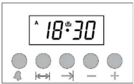
-
The oven is in operation.
-
If the set countdown time has elapsed, an acoustic signal sounds, the oven is switched off automatically and the operational status indicator of the automatic cooking / baking function flashes: « ✗ » (s. fig. below).
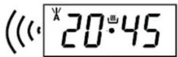
- After approx. 7 minutes, the acoustic signal stops automatically.
After the cooking / baking process is finished: always turn the rotary knobs for the oven functions and the temperature control to position OFF « ● » to switch off the oven completely.
HOW TO RESET THE OVEN
After using the semi-automatic cooking and baking function, the oven must be reset to standard mode (standby mode). Otherwise, you cannot use the appliance any further.
➢ Press the buttons « DURATION OF THE COOKING / BAKING TIME |↔| » and « END OF THE COOKING / BAKING TIME → » once simultaneously to reset the oven (s. fig. below). The oven returns to standby mode after a few seconds.
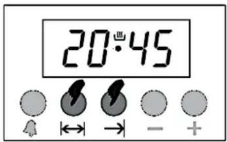
WARNING! To switch off the oven completely the rotary knobs of the oven function and the temperature control must be set to position OFF « ● ». If the rotary knobs are not set to position OFF « ● » while resetting the oven, the oven starts to heat again.
HOW TO CANCEL THE PROGRAMMING
You can cancel the programming at any time.
➢ Press the buttons « DURATION OF THE COOKING / BAKING TIME |↔| » and « END OF THE COOKING / BAKING TIME → |» once simultaneously. The oven returns to standby mode after a few seconds.
Always turn the rotary knobs for the oven functions and the temperature control to position OFF « ● » to switch off the oven completely.
HOW TO SET THE END OF THE COOKING / BAKING TIME
Using this function, you can select the time of the day at which the oven will be switched off automatically.
Do not forget to set the desired oven function (s. chapter 4.5 OVEN FUNCTIONS) and oven temperature using the corresponding rotary knobs.
- The oven must be in STANDBY MODE. In STANDBY MODE, the LED display indicates the current time / system time (e.g.: 18:30 / s. fig. below). The operational status indicator « OVEN ON STANDBY » must be lit on the LED display: « »(s. fig. below).

- Place the food to be cooked or baked in the oven and close the door properly.
- Press the « END OF THE COOKING / BAKING TIME → » - BUTTON once to enter the setting mode of this automatic function.
- The display indicates « 0:00 » and the operational status indicator of the automatic cooking function flashes: « ✗ » (s. fig. below).
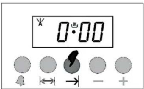
- Set the desired time of the day at which the cooking / baking process should be finished using the « +/ - » - BUTTONS (e.g.: 21:30 / s. fig. below).
i Please note that the appliance is equipped with a 24-hour display. E.g.: if you want to set the time « 9.30 p.m. », you must set the display to 21.30, etc. (s. fig. below).

- After approx. 5 seconds, the set time of the day is saved. The operational status indicator of the automatic cooking / baking function is on permanently: « A » (s. fig. below). The display indicates the current time / system time again (s. fig. below).

-
The oven is in operation.
-
If the set time of the day has been reached, an acoustic signal sounds, the oven is switched off automatically and the operational status indicator of the automatic cooking / baking function flashes: « ✗ » (s. fig. below).

- After approx. 7 minutes, the acoustic signal stops automatically.
After the cooking / baking process is finished: always turn the rotary knobs for the oven functions and the temperature control to position OFF « ● » to switch off the oven completely.
HOW TO RESET THE OVEN
✿ After the oven has reached the set time of the day and is switched off automatically, it must be reset to standard mode (standby mode). Otherwise, you cannot use the appliance any further.
➢ Press the buttons « DURATION OF THE COOKING / BAKING TIME |↔| » and « END OF THE COOKING / BAKING TIME → » once simultaneously to reset the oven (s. fig. below). The oven returns to standby mode after a few seconds.

⚠ WARNING! To switch off the oven completely the rotary knobs of the oven function and the temperature control must be set to position OFF « ● ». If the rotary knobs are not set to position OFF « ● » while resetting the oven, the oven starts to heat again.
HOW TO CANCEL THE PROGRAMMING
You can cancel the programming at any time.
➢ Press the buttons « DURATION OF THE COOKING / BAKING TIME |↔| » and « END OF THE COOKING / BAKING TIME → | » once simultaneously. The oven returns to standby mode after a few seconds.
Always turn the rotary knobs for the oven functions and the temperature control to position OFF « ● » to switch off the oven completely.
4.4.3 Automatic cooking / baking function
Using this function, you can select the duration of the cooking / baking time and the time of the day at which the oven will be switched off automatically at the same time.
Do not forget to set the desired oven function (s. chapter 4.5 OVEN FUNCTIONS) and oven temperature using the corresponding rotary knobs.
HOW TO SET THE AUTOMATIC COOKING / BAKING FUNCTION
- The oven must be in STANDBY MODE. In STANDBY MODE, the LED display indicates the current time / system time (e.g.: 18:30 / s. fig. below). The operational status indicator « OVEN ON STANDBY » must be lit on the LED display: « ”(s. fig. below).

- Place the food to be cooked or baked in the oven and close the door properly.
- Press the « DURATION OF THE COOKING / BAKING TIME |↔| » - BUTTON once to enter the setting mode of this automatic function.
- The display indicates « 0:00 » and the operational status indicator of the automatic cooking function flashes: « » (s. fig. below).

- Set the desired duration of the cooking / baking time using the « +/- » - BUTTONS (e.g.: 2 hours and 15 minutes / s. fig. below).

- After approx. 5 seconds, the set time is saved and the countdown begins. The operational status indicator of the automatic cooking / baking function is on permanently: « A » (s. fig. below). The display indicates the current time / system time again (s. fig. below).
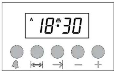
-
Press the « END OF THE COOKING / BAKING TIME → » - BUTTON once to enter the setting mode of this automatic function.
-
The display indicates « 0:00 » and the operational status indicator of the automatic cooking function flashes: « » (s. fig. below).

- Set the desired time of the day at which the cooking / baking process should be finished using the « +/- » - BUTTONS (e.g.: 21:30 / s. fig. below).
i Please note that the appliance is equipped with a 24-hour display. E.g.: if you want to set the time « 9.30 p.m. », you must set the display to 21.30, etc. (s. fig. below).
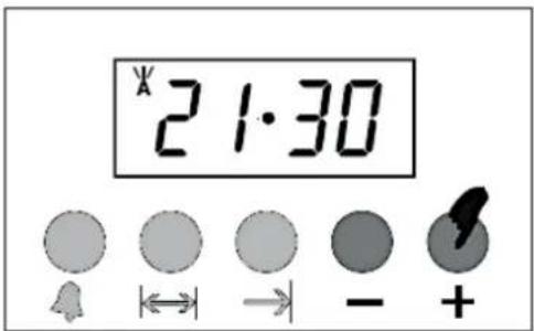
- After approx. 5 seconds, the set time of the day is saved. The operational status indicator of the automatic cooking / baking function is on permanently: « A » (s. fig. below). The display indicates the current time / system time again (s. fig. below).

-
The oven is in operation.
-
The cooking / baking process starts at the calculated time of the day (19:15).
- At the end of the cooking / baking process, an acoustic signal sounds, the oven is switched off automatically and the operational status indicator of the automatic cooking / baking function flashes: « ✗ » (s. fig. below).

- After approx. 7 minutes, the acoustic signal stops automatically.
After the cooking / baking process is finished: always turn the rotary knobs for the oven functions and the temperature control to position OFF « ● » to switch off the oven completely.
EXAMPLE
i Please note that the appliance is equipped with a 24-hour display. E.g.: if you want to set the time « 9.30 p.m. », you must set the display to 21.30, etc.
It is 6:30 p.m. (24-hour display = 18:30). You want to cook or bake for 2 hours. The cooking / baking time should be finished at 9:30 p.m. (24-hour display = 21:30).
To set the programme, please follow the instructions given above in: « HOW TO SET THE AUTOMATIC COOKING / BAKING FUNCTION ».
-
Set the duration of the cooking / baking time to 2 hours and 15 minutes.
-
Set the time at which the cooking / baking process should be finished to 21:30 (9:30 p.m.).
-
The calculated cooking process starts at 19:15 (7:15 p.m.).
-
At 21:30 (9:30 p.m.) the oven will be switched off automatically.
i After the cooking / baking process is finished: always turn the rotary knobs for the oven functions and the temperature control to position OFF « ● » to switch off the oven completely.
HOW TO RESET THE OVEN
✿ After the oven has reached the set time of the day and is switched off automatically, it must be reset to standard mode (standby mode). Otherwise, you cannot use the appliance any further.
➢ Press the buttons « DURATION OF THE COOKING / BAKING TIME |↔| » and « END OF THE COOKING / BAKING TIME → | » once simultaneously to reset the oven (s. fig. below). The oven returns to standby mode after a few seconds.

⚠ WARNING! To switch off the oven completely the rotary knobs of the oven function and the temperature control must be set to position OFF « ● ». If the rotary knobs are not set to position OFF « ● » while resetting the oven, the oven starts to heat again.
HOW TO CANCEL THE PROGRAMMING
You can cancel the programming at any time.
➢ Press the buttons « DURATION OF THE COOKING / BAKING TIME |↔| » and « END OF THE COOKING / BAKING TIME → | » once simultaneously. The oven returns to standby mode after a few seconds.
Always turn the rotary knobs for the oven functions and the temperature control to position OFF « ● » to switch off the oven completely.
4.4.4 Selection of the acoustic signal
You can select three various acoustic signals.
The TIMER / PROGRAMME FUNCTIONS must not be activated and the operational status indicator « OVEN ON STANDBY » must be lit on the LED display: « 📄 » (s. chapter 4.3.2 STANDBY MODE).
HOW TO SELECT AN ACOUSTIC SIGNAL
- Press and hold the « - » - BUTTON.
- The currently set acoustic signal sounds.
- Press and hold the « - » - BUTTON a second time.
- The second selectable acoustic signal sounds.
- Press and hold the « - » - BUTTON a third time.
- The third selectable acoustic signal sounds.
- This procedure can be repeated as needed.
- If you have selected the desired acoustic signal, release « - » - BUTTON.
- The display changes to the current time of the day and the set acoustic signal is activated.
The factory setting is a high-pitched acoustic signal. In the event of a prolonged power failure, the individually set acoustic signal is reset to the factory-set signal.
4.4.5 Power failure
POWER FAILURE: IMPORTANT NOTES REGARDING THE GAS HOB
In the event of a power failure or ignition failure, you can use a commercially available gas lighter or an extra-long match to ignite the burner flame. In such a case, be especially careful. RISK OF BURNS!
⚠ WARNING! In such a case, do not use a normal lighter or a normal match to ignite the burner flame. RISK OF BURNS!
POWER FAILURE: IMPORTANT NOTES REGARDING THE OVEN
In the event of a power failure, any cooking process is interrupted. Turn the rotary knobs for the oven functions and the temperature control to position OFF « ● » to switch off the oven completely.
After a power failure: the display indicates « 0:00 » and the indicator « A » flashes. Press the buttons « DURATION OF THE COOKING / BAKING TIME |↔|» and « END OF THE COOKING / BAKING TIME →|» once simultaneously to enter the time setting mode. Set the current time (s. chapter 4.3.3 SETTING OF THE TIME / SYSTEM TIME).
Before you can use the oven properly, you must set the current time / system time.
⚠ WARNING! During a power failure: Ensure that the rotary knobs of the oven function and the temperature control are each set to position OFF « ●» to switch off the oven completely. If the rotary knobs are not set to position OFF « ● », the oven will start heating again as soon as the power is available again.
4.5 Oven functions
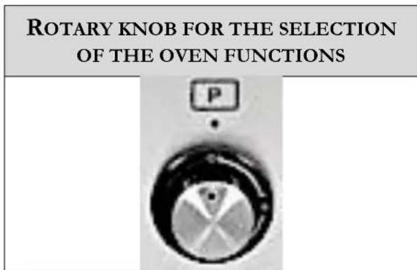
Fig. similar: modifications are possible.
INTERNAL LIGHT
Depending on model, the oven may have a separately switchable internal light. This can be switched on by pressing the « INTERNAL LIGHT » - BUTTON on the control panel (s. chapter 3.4 VIEW OF THE CONTROL PANEL: ROTARY KNOBS AND OPERATING BUTTONS); independent of any other oven function. The oven does not heat.
If your appliance model does not have a separately switchable internal light (the «INTERNAL LIGHT ☐» - BUTTON on the control panel is not present or without function), the internal light will switch on as soon as an oven function is set.
| SYMBOLS | DESCRIPTION OF THE FUNCTIONS |
 | DEFROSTNo temperature setting: the fan works without a heat setting. Only the fan operates.Reduces the defrosting time of frozen food.Defrosting time depends on size and weight of the food. Th defrosting time can also be found in the instructions on the label of the food packaging.In this way, hot food or the interior can also be cooled. |
  | TOP HEAT AND BOTTOM HEATThe oven is heated conventionally.The oven should be preheated before you start cooking / baking.You can grill / cook on one cooking level.BOTTOM HEAT INCL. FANSwitches on the bottom heat of the oven, e.g. for final backing from the bottom (e.g.: pizza, etc.).Due to the fan, the heat circulates; this circulation ensures an even cooking and baking result.This function is also suitable for the sterilising and preserving of jars. |
 | TOP HEAT INCL. FANSwitches on the top heater of the oven (e.g. for final backing from the top).Due to the fan, the heat circulates; this circulation ensures an even cooking and baking result. |
 | TOP AND BOTTOM HEAT INCL. FANThe oven is heated conventionally while using the fan.Due to the additionally activated fan, the heat circulates; this circulation ensures an even heat distribution.The oven temperature rises slowly and the heat can penetrate the food completely. This reduces excess heat and makes grilling more energy efficient.This function is suitable for roasting at high temperatures or for the roasting of large pieces of meat. |
  | GRILL ELEMENTThis function switches on the grill element only.Preheat the grill for approx. 5 minutes.Place the grill pan in the 4th or 5th rack of the oven: counte from the bottom of the oven (lowest rack height) upwards.The heat is emitted directly onto the food under the grill element.Grilling allows higher temperatures in the top area and intensifies browning; it also allows the preparing of larger portions. (e.g. of sausages, steaks, fish, etc).HOT AIR FANThe fan is surrounded by a heating element, so the hot air is evenly distributed.Advantages of the hot air function:no preheating when cooking for more than 20 minutes.no flavour transfer when cooking different foods at the same time.less energy consumption.10 % faster cooking than conventional functions.You can cook on two cooking / baking levels simultaneously. |
NOTICE! If you select an oven function with « FAN » and set the temperature control knob to position OFF « ●» at the same time, only the fan operates and you can cool down food / dishes or the interior of the oven.
5. Environmental protection
5.1 Environmental protection: disposal
Appliances bearing this symbol « — » must not be disposed of together with household waste throughout the EU. To prevent potential damage to the environment or human health from uncontrolled waste disposal and to promote the sustainable reuse of material resources, responsibly supply the appliance to a recycling centre.
5.2 Environmental protection: energy saving
◆ Use proper cookware for cooking.
✿ Cookware with thick, flat bases can save up to 1/3 of electric energy. Remember to cover your cookware if possible; otherwise, you will use four times as much energy!
◆ The diameter of the cookware should match the burner size.
Make sure that the burners and the bottom of the cookware are clean.
Soils prevent heat-transfer. Repeatedly burnt-on spillages can often be removed by products, which will damage the environment, only.
Do not uncover the cookware too often (a watched pot-content will never boil!).
◆ Decrease the power level as soon as the desired cooking temperature is reached.
◆ Use pot-lids to shorten cooking times and save energy.
- Minimise the amount of cooking liquids or fat/oil to shorten cooking times.
Select a high-power level when you start cooking. Reduce the power level when your food has been heated up.
Do not open the oven door unnecessarily often.
❖ Switch off the oven in good time and make use of the residual heat.
❖ Only use the oven when cooking larger dishes.
◆ Meat of up to 1 kg can be cooked more economically in a pan on the hob.
❖ Make use of the residual heat of the oven.
If the cooking time takes longer than 40 minutes, switch off the oven 10 minutes before.
For baking it is better to use black trays which conduct heat better and shorten the baking time.
◆ Make sure the oven door is closed properly.
- Heat can escape through spillages on the door seals. Clean up any spillages immediately.
Do not install the oven / hob near of refrigerators / freezers. Otherwise, the energy consumption increases unnecessarily.
6. Cooking guidelines
⚠ WARNING! The appliance must not leave unattended during cooking.
⚠ WARNING! Never close the glass cover of the appliance while the gas hob and / or the electric oven are in operation.
⚠ WARNING! Be very careful when frying because oil and fat heat up very fast especially when operating a high-power level. Extremely hot oil and fat inflame spontaneously and represent a serious fire risk.
⚠ WARNING! NEVER try to extinguish a fire with water but switch off the appliance and then cover the flame e.g. with a lid or a fire blanket.
⚠ WARNING! Never touch the gas burners and / or the pot grids while they are still hot. RISK OF BURNS!
⚠️ CAUTION! The interior parts of the appliance become extremely hot. Do not touch any parts inside the appliance if you handle your cookware. RISK OF BURNS!
⚠️ CAUTION! Be careful if you open the door. Do not get in contact with the hot parts of the oven or the steam, which will escape the oven. RISK OF BURNS! RISK OF SCALDING!
⚠️ CAUTION! Cooking utensils may become hot because of the heat transferred by the heated food. Potholders or oven gloves may be needed to handle such utensils.
NOTICE! Only use cookware suitable for gas hobs / gas burners.
NOTICE! Check your utensils if they are suitable for the use in an oven. Use suitable ovenware only.
6.1 Tips for cooking and frying on a gas hob
SIMMERING / COOKING OF RICE
- Simmering is cooking with a temperature of approx. 85 °C. At this temperature small bubbles ascend to the surface of the cooking liquid. Simmering is a perfect way to cook delicious soups and stews as the flavours of the food unfold completely without being over-heated. You should also cook egg-based sauces and sauces thickened with flour in this way.
Some cooking procedures, including the cooking of rice with the absorption-method (= the water is consumed completely), require a setting above the lowest power level, so the food is cooked within the recommended cooking time.
STEAKS
- Take the meat out of the fridge and let it rest at room temperature for approx. 20 minutes.
- Heat up a pan with a heavy base.
- Rub both sides of the steak with oil. Drizzle a small amount of oil into the hot pan and place the steak into the pan.
- Turn the meat just once while cooking. The exact cooking time depends on the size of your steak and your individual preferences (medium, medium rare etc.). So, the cooking time of each side may vary from 2 to 8 minutes. Press the steak to check the cooking result - a firm steak is well done.
- Leave the steak on a warm plate for a few minutes; so it will become tender.
ASIAN-STYLE COOKING
- Choose a wok with a flat base or a big pan suitable for a gas hob.
- Prepare all ingredients and the cooking utensils you need. Asian-style cooking should work fast. If you want to cook a big amount of food, you should divide the food into several portions.
- Preheat the wok / pan briefly and add two tablespoons of oil.
- Cook the meat first. Put it aside and keep it warm.
- Now cook the vegetable. When the vegetable is hot but still crisp, reduce the power level. Add the meat and, if desired, a sauce.
- Sauté the complete food carefully so all components are hot.
- Serve immediately.
6.2 Tips for baking and roasting in an oven
We recommend using the supplied baking tray provided with your appliance.
It is also possible to bake in cake tins and trays bought somewhere else. For baking it is better to use black trays which conduct heat better and shorten the baking time.
◆ Shapes and trays with bright or shiny surfaces are not recommended when using the conventional heating method (top and bottom heaters). The use of such tins can result in under-cooking the base of cakes.
Before you take a cake out of the oven, check that it is ready using a wooden stick (when the cake is ready the stick should come out dry and clean after having been inserted in the cake).
When switching off the oven leave the cake inside for about 5 minutes.
◆ Cook meat with a weight of more than 1 kg in the oven. Cook smaller pieces of food on the hob.
Use oven-proof cookware only. Check that their handles also are oven-proof.
When you cook meat on a grilling grate, insert a drip tray with a small amount of water in the oven (minimum rack height).
❖ Turn over meat at least once. Pour hot gravy or hot salted water over the meat.
❖ Never pour cold water over the meat.
6.2.1 Examples of baking and roasting food in an oven
In the following table you will find examples of baking and roasting food in an oven.
The temperatures given in the following table are guidelines only. They depend on the quality and of the combination of the food to be cooked.
The cooking times given in the following table are guidelines only. The respective cooking time depends on the cookware used as well as on the quality, temperature and consistency of the foods and may vary accordingly.
i The table does not claim to be complete.
The manufacturer does not give any guarantee and accepts no liability for the accuracy or completeness of the following table.
⚠️ CAUTION! Cooking utensils may become hot because of the heat transferred by the heated food. Potholders or oven gloves may be needed to handle such utensils.
| FOOD | WEIGHT | OVEN FUNCTION* | INSERTION HEIGHT** | TEMPERATURE | COOKING TIME*** |
|
| MEAT |
| Roast veal | 1.00 kg |  | 2 | 150 - 170 °C | 65 - 90 min. |
| Pork loin | 1.00 kg |  | 2 | 180 - 190 °C | 70 - 80 min. |
| Pork shoulder | 1.00 kg |  | 2 | 180 - 190 °C | 90 - 100 min. |
| Roast rabbit | 1.00 kg |  | 2 | 180 - 190 °C | 80 - 100 min. |
| Turkey breast | 1.00 kg |  | 2 | 180 - 190 °C | 110 - 120 min. |
| Pork neck | 1.00 kg |  | 2 | 180 - 190 °C | 190 - 210 min. |
| Chicken | 1.00 kg |  | 2 | 170 °C | 70 - 90 min. |
| GRILLED MEAT |
| Pork tenderloin pieces | - |  | 3 | 250 - 280 °C | One side:9 - 11 min.Other side:5 - 9 min. |
| Beef tenderloin pieces | - |  | 3 | 250 - 280 °C | One side:9 - 11 min.Other side:9 - 11 min. |
| Meat balls | - |  | 3 | 250 - 280 °C | One side:7 - 9 min.Other side:5 - 6 min. |
| FISH |
| Salmon trout | 0.70 kg |  | 2 | 160 - 170 °C | 35 - 40 min. |
| MISCELLANEOUS |
| Lasagne | 3.00 kg |  | 2 or 3 | 210 - 230 °C | 30 - 40 min. |
| Pasta, gratinated | 3.00 kg |  | 2 or 3 | 210 - 230 °C | 30 - 40 min. |
| Pizza | - |  | 2 or 3 | 230 °C | 10 - 15 min. |
| Bread | - |  | 2 | 190 - 200 °C | 25 - 30 min. |
| Focaccia | - |  | 2 | 180 - 190 °C | 15 - 20 min. |
| CAKES / BISCUITS / DESSERTS |
| Donuts | - |  | 2 | 160 °C | 55 - 60 min. |
| Fruitcake | - |  | 2 | 160 °C | 30 - 35 min. |
| CAKES / BISCUITS / DESSERTS |
| Fruitcake | - |  | 2 | 170 °C | 35 - 40 min. |
| Shortcrust pastry | - |  | 2 | 160 - 170 °C | 20 - 25 min. |
| Jam tarts | - |  | 2 | 160 °C | 20 - 25 min. |
| Paradise cake | - |  | 2 | 160 °C | 55 - 60 min. |
| Paradise cake | - |  | 2 | 170 °C | 55 - 60 min. |
| Eclair | - |  | 2 | 150 - 160 °C | 40 - 50 min. |
| Light biscuit cake | - |  | 2 | 150 - 160 °C | 45 - 50 min. |
| Rice pudding | - |  | 2 | 160 °C | 40 - 50 min. |
| Rice pudding | - |  | 2 | 170 °C | 50 - 60 min. |
| Croissants | - |  | 2 | 160 °C | 25 - 30 min. |
| Apple pie | - |  | 3 | 180 °C | 55 - 60 min. |
| Shortbread biscuits (on several levels) | - |  | 2 and 4 | 160 - 170 °C | 16 - 20 min. |
| Croissants (on several levels) | - |  | 2 and 4 | 160 - 170 °C | 16 - 20 min. |
|  | TOP AND BOTTOM HEAT |
| *OVENFUNCTIONS |  | TOP AND BOTTOM HEAT (+FAN) |
 | GRILL |
 | HOT AIR |
| ** | INSERTIONHEIGHT | The insertion heights given in the table above are counted from the bottom of the oven (e.g.: insertion height 2 = 2nd insertion height from the bottom of the oven). |
| *** | COOKINGTIME | The cooking / baking times given in the table above do not include the preheating times.Preheat the oven for 5 - 10 minutes before baking / roasting. |
6.3 Tips for grilling in an oven
- Turn the rotary knob for the selection of the oven functions until the desired grill function is displayed.
- Preheat the oven for approx. 4 minutes.
- When you grill your food on a grilling grate, also insert a drip tray to catch the dripping grease and to keep the appliance clean.
- Always keep the door of the oven closed.
- Turn your food over after half of the grilling-time.
- Spread your food with a little bit of oil before grilling.
NOTICE! Do not use aluminium foil for grilling. Do not wrap your food in aluminium foil and do not cover the grillage with aluminium foil. The aluminium foil will reflect the heat of the grill so the appliance may be damaged.
NOTICE! Do not place the drip tray (oven pan) or the baking tray (deep oven pan) ^45 in the upper levels (3 / 4 / 5) ^46 of the oven. The intense heat in the upper levels of the oven can warp the material of the accessories so that the interior of the oven can be damaged when removing the drip tray / baking tray. RISK OF DAMAGE!
⚠ WARNING! Switch off the appliance and let it cool down completely before cleaning. Disconnect the appliance from the mains before maintenance (fuse box of your household power supply)!
⚠ WARNING! Never use a steam cleaner to clean the appliance. The steam will cause serious damage to the electric components of the appliance. RISK OF ELECTRIC SHOCK!
⚠ VORSICHT! To switch off the oven completely, you must turn both the rotary knob for the selection of the oven functions and the rotary knob for the selection of the oven temperature to position OFF « ● ».
⚠️ CAUTION! To switch off the hob completely, all of the relevant rotary knobs must be set to position OFF « ● ».
DETERGENTS
Do not use any abrasive detergents!
➢ Do not use any organic detergents! ^47
Do not use essential oils!
▶ Never use solvents.
NOTICE! Any damage that is caused to the appliance by a cleaning product will not be fixed free of charge, even if the guarantee period of the appliance is still valid.
7.1 Cleaning of the gas hob
HOW TO CLEAN THE SURFACE OF THE GAS HOB
▶ Clean the hob after each use.
➢ Remove residuals on the surface using a soft cloth. Dip the cloth into warm water which contains a small amount of washing-up liquid, then wring out thoroughly.
➢ Never use household cleaners or bleach, steel wool, bathtub and sink cleaners, abrasive or acrid detergents.
HOW TO CLEAN ENAMELLED SURFACES
➢ Use a damp cloth and a mild detergent.
➢ Remove fat with warm water or a special detergent for enamel.
Do not use any abrasive detergents.
➢ Do not use any organic detergents (lemon juice, vinegar etc.)
HOW TO CLEAN THE POT GRIDS
➢ Be careful when drying. The holders have rough edges which may hurt your hands.
➢ Remove persistent contamination using a suitable cleaning paste.
FOR ENAMELLED SURFACES ONLY: the constant contact of the pot grids with the flame of the gas burners may cause changes to the enamelled surfaces over time -due to the heat-. This is normal and does not affect the correct operation of the appliance.
FOR CAST IRON POT GRIDS ONLY (optional) ^48 : if you use cast iron pot grids (optional accessory) and cookware with aluminium bases, white residues may appear on the pot grids. These residues are caused by friction of the cookware base against the pot grids. These residues on the pot grids are difficult to remove by normal cleaning. Therefore, only use cookware that is suitable for cast iron pot grids.
HOW TO CLEAN A GAS BURNER
NOTICE! The individual components must not be cleaned in the dishwasher.
➢ You can remove the burner cap and burner crown for cleaning.
Clean the parts using hot soapy water and remove contaminations using a suitable cleaning paste.
➢ Check that the openings in the burner crowns are not blocked.
The individual parts of the gas burner (burner cap / burner crown) must be completely dry before you reinstall them.
➢ After cleaning a gas burner, check whether the burner crown (2) is placed on the respective gas burner properly. The openings (a / arrows) in the burner crown (2) must be aligned with the ignition electrode (5) and the thermocouple (6) correctly (s. fig. below).
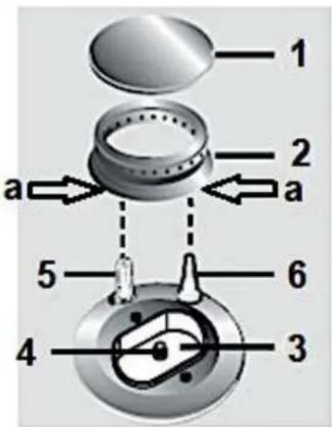
Fig. similar: modifications are possible.
| 1 | BURNER CAP |
| 2 | BURNER CROWN |
| 3 | BURNER PLATE |
| 4 | BURNER-JET |
| 5 | IGNITION ELECTRODE |
| 6 | THERMOCOUPLE^49 |
Please check that the burner caps are placed on the burner crowns exactly (s. fig. below).
 |  |
| RIGHT | WRONG |
IGNITION ELECTRODES AND THERMOCOUPLES (s. fig. above and below)
For proper operation, the ignition electrodes and thermocouples must always be perfectly clean. Therefore, always keep the ignition electrodes and thermocouples in the cleanest possible condition.
The thermocouple is extremely important because it is responsible for shutting off the gas supply if the burner flame extinguishes unintentionally during cooking.
➢ Check the ignition electrodes and thermocouples frequently and clean them carefully with a damp cloth if necessary.
Dry residues can be removed carefully using a wooden toothpick or needle.

Fig. similar: modifications are possible.
| 1 | BURNER CAP |
| 2 | BURNER CROWN |
| 5 | IGNITION ELECTRODE |
| 6 | THERMOCOUPLE ^50 |
7.2 Cleaning of the glass cover
The glass cover of the appliance can be removed for easier cleaning.
➢ Be extremely careful when cleaning the glass cover.
Do not use abrasive cleaners, otherwise you may scratch and / or break the glass cover. Also, never use household cleaners or bleach, steel wool, bathtub or sink cleaners or corrosive detergents.
Use only a soft cloth for cleaning. Dip the cloth into warm water which contains a small amount of washing-up liquid, then wring out thoroughly.
HOW TO REMOVE / INSTALL THE GLASS COVER
- Open the glass cover (2) of the gas hob (1 / s. fig. on the right).
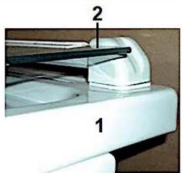
Fig. similar.
- Hold the glass cover (2) on both sides with your hands and pull it carefully upwards out of the guide rail (3 / see arrow, fig. right).

Fig. similar.
- To reinstall the glass cover, hold it on both sides with your hands. Then insert the glass cover into the guide rail carefully.
- Ensure that the glass cover is inserted in the guide rail securely and properly.
- Close the glass cover.
i Be very cautious and careful with the glass cover during the entire removal, installation and cleaning process so that it does not get scratched or possibly even break.
WARNING! If the glass cover has not been installed properly, it may slip out of the guide rail when opening or closing; it is possible that the glass cover may be damaged or even broken thereby. RISK OF INJURY! RISK OF DAMAGE!
WARNING! Ensure that you never touch the glass cover of the gas hob with pots and pans that are still hot. The glass may crack and break due to the heat. RISK OF INJURY! RISK OF DAMAGE!
NOTICE! Never place objects of any kind on the glass cover. The glass cover is to be used to cover the (cooled) gas hob only and must not be misused as a storage place for objects.
NOTICE! If liquids are spilled on the closed glass cover, remove them immediately and carefully using a soft cloth before you open the glass cover.
NOTICE! Any damage that is caused to your appliance by improper removal or installation of the glass cover will not be fixed free of charge, even if the guarantee period of the appliance is still valid.
7.3 Cleaning of the oven
⚠ WARNING! Never use a steam cleaner! RISK OF ELECTRIC SHOCK!
NOTICE! If you use a special oven-detergent, check that the detergent is suitable for your appliance (instructions on the packaging of the detergent).
NOTICE! Any damage that is caused to the appliance by a cleaning product will not be fixed free of charge, even if the guarantee period of the appliance is still valid.
- Clean the oven after each use.
- Clean the interior with warm water and a little bit of washing-liquid. Use a sponge or a soft cloth. Never use abrasive or aggressive detergents.
- Dry thoroughly after cleaning.
- Clean the outside of the oven with warm soapy water. Use a sponge or a soft cloth. Never use abrasive or aggressive detergents.
7.3.1 How to clean the oven with steam
- Place a bowl of 250 ml of water at the lowest rack height of the oven.
- Close the oven door.
- Select the oven function « bottom heat (incl. fan) » and set the oven temperature to 100 °C.
- Heat the oven for approx. 30 minutes (see also chapter 4.3 USE OF THE OVEN et seq.).
- Open the oven door and wipe the interior with a cloth.
- Then clean the interior using warm water and a little bit of washing-liquid.
- Dry after cleaning.
7.4 Cleaning of the oven door
▶ Clean the door very carefully.
➢ Do not use any abrasive detergents; otherwise, you may damage or break the glass.
▶ Use wash-up liquid and warm water.
NOTICE! Do not scratch the glass.
7.5 Removal / installation of the oven door
To allow a thorough cleaning of the oven, the oven door can be removed.
HOW TO REMOVE / INSTALL THE OVEN DOOR
| 1. Open the oven door and push the safety catches (1) of the two hinges (2) upwards (s. fig. on the right). | 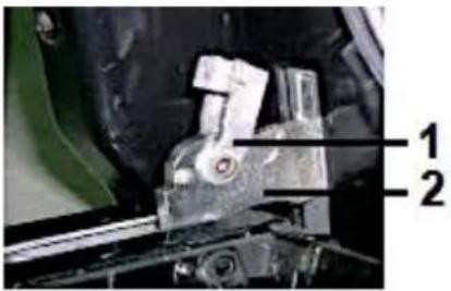 |
 |
| Fig. similar. |
| 2. Close the door slightly: 45° angle (s. fig. on the right).3. Lift the door and pull it towards your direction carefully. |  |
| Fig. similar. |
- To reassemble proceed in reverse order.
- Check that the groove of the hinge bracket is positioned properly in its guide.
- After reassembling the door, close the safety catch carefully.
- If the safety catch is not closed properly, you will damage the hinges when closing the door.
NOTICE! Any damage that is caused to your appliance by improper removal or installation of the oven door will not be fixed free of charge, even if the guarantee period of the appliance is still valid.
7.5.1 Removal / installation of the door seal
To enable even more thorough cleaning of the oven, the door seal can be removed.
HOW TO REMOVE / INSTALL THE SEAL OF THE OVEN DOOR
-
You must remove the oven door first (s. chapter 7.5 REMOVAL-/INSTALLATION OF THE OVEN DOOR).
-
Loosen the door seal (1) at the four corners of the oven as shown in the picture on the right.
-
You can then carefully release the seal (1) from its guide rail (2) and remove it.

Fig. similar.
- To reinsert the door seal, align it with a corner of the oven. Press the seal in the corner of the oven into its guide rail. Then gradually press the rest of the door seal into the guide rail.
- Ensure that the door seal is properly installed. The seal must close properly.
- Reinstall the oven door properly (see chapter 7.5 REMOVAL / INSTALLATION OF THE OVEN DOOR).
⚠ WARNING! If the door seal of the oven is damaged, you must not use the oven until a new door seal has been installed. Use an original door seal only. Please contact the aftersales service or the shop you purchased the appliance at. ^51
NOTICE! Align the door seal properly with the oven. The seal must close properly. The oven must not be used without a properly installed door seal.
NOTICE! Any damage that is caused to your appliance by improper removal or installation of the door seal will not be fixed free of charge, even if the guarantee period of the appliance is still valid.
7.6 Removal / installation of the side racks (depending on model)
✿ Depending on your appliance model, you can remove the side racks to facilitate the cleaning of the oven cavity (especially the side panels).
If your appliance model is equipped with integrated side racks, you cannot remove them!
Remove all accessories such as the grilling grate, drip tray, etc. before you remove the side racks.
NOTICE! Only carry out the removal / installation of the side racks with utmost care, otherwise you may damage the enamel.
HOW TO REMOVE / INSTALL THE SIDE RACKS
| 1. Press the hook (A) of the side rack slightly downwards (s. fig. on the right, arrow). |  |
| 2. Swivel the side rack inwards at an angle of approx. 45 degrees (s. fig on the right, arrow). |  |
| 3. Unhook the side rack at the top and then pull it out carefully (s. fig. on the right, arrows). |  |
| 4. Please proceed in reverse order to install the side racks.5. Ensure that the side racks are installed properly and securely. |
NOTICE! Any damage that is caused to your appliance by improper removal or installation of the side racks will not be fixed free of charge, even if the guarantee period of the appliance is still valid.
7.7 Replacing of the illuminant
⚠ WARNING! Switch off the appliance and let it cool down completely. Disconnect the appliance from the mains before maintenance (fuse box of your household power supply)! RISK OF ELECTRIC SHOCK!
NOTICE! When you replace the illuminant, always use a clean cloth or gloves. Never touch the new illuminant with your bare hands.
NOTICE! Never use a screwdriver to remove the cover. Remove the cover by hand only! RISK OF DAMAGE!
- Disconnect the appliance from the mains: switch off the corresponding fuse in the fuse box of your household power supply!
- Place a dishcloth in the interior of the cold oven to protect it from possible damage.
- Unscrew the lamp cover (A) anticlockwise (s. fig. below). Clean the lamp cover and wipe it dry thoroughly.
- Unscrew the illuminant (B) from the socket (s. fig. below) and replace it with a high temperature illuminant (300 °C) of the same type: voltage 230 V / power 25 W. Do not use any other type of illuminant.

Fig. similar: modifications are possible.
- Screw the new illuminant in. Check its proper position in the socket.
- Reinstall the lamp cover.
- Remove the dishcloth and switch on the corresponding fuse in the fuse box of your household power supply again.
According to the EU regulation No. 244/2009, your appliance is classified as a household appliance in accordance with the eco-design requirements for non-directional household lamps. This means that illuminants, which are used in household appliances, must not be used to illuminate domestic establishments.
NOTICE! Any damage that is caused to your appliance by improper replacement of the illuminant will not be fixed free of charge, even if the guarantee period of the appliance is still valid.
8. Troubleshooting
⚠️ DANGER! Never try to repair the appliance yourself. Repairs carried out by unauthorised persons can cause serious damage. If the appliance does not operate properly, please contact the aftersales service or the shop you purchased the appliance at. ^52
⚠️ DANGER! Never try to detect a gas leakage using matches; use soapy water.
Check the technical condition of the gas supply regularly. If any damage occurs, a qualified professional (gas fitter) must repair the gas connection. You must replace the hose-connections regularly; always consult a qualified professional (gas fitter) therefor. A qualified professional (gas fitter) should lubricate the burners regularly. Consult a qualified professional (gas fitter) if you detect any abnormal operation modes.
If your appliance does not operate properly, check points 1 and 2 below.
- The gas conduction seems to be abnormal. Check that
a. the holes of the burner are not blocked.
b. the pressure controller operates properly.
c. the appliance is supplied with gas properly.
- Odour of gas in the room. Check that
a. the rotary knob is in position OFF.
b. the gas inlet valve is positioned properly.
c. the gas inlet valve is in a proper condition.
EMERGENCY MEASURES
- Switch off the entire appliance.
- Disconnect the appliance from the mains (fuse box of your household power supply) and close the gas shut-off valve.
- Contact your aftersales service or the shop you purchased the appliance at.
➢ Check the schedule below before you contact your aftersales service or the shop you purchased the appliance at.
| MALFUNCTION |
| POSSIBLE CAUSES | MEASURES |
| THE APPLIANCE DOES NOT WORK AT ALL. |
| 1. The appliance is not supplied with energy. | 1. Check that the appliance is connected to the mains. Check the household fuse box. Is there a power failure at your place of residence? |
| SPARK IS NOT GENERATED. |
| 1. The appliance is not supplied with energy.2. The burner cap and / or burner crown are not installed properly. | 1. Check that the appliance is connected to the mains. Check the household fuse box. Is there a power failure at your place of residence?2. Check the proper arrangement of the burner cap / crown. |
| THE FLAME BURNS UNEVENLY IN THE BURNER CROWN. |
| 1. The main jet is blocked.2. the burner crown is contaminated.3. The burner cap and / or burner crown are not installed properly. | 1. Clean the main jet.2. Clean the burner crown. Check that the main jet and the holes of the burner crown are not blocked.3. Check the proper arrangement of the burner cap / crown. |
| SOME COOKWARE MAKE CRACKING OR CLICKING NOISE. |
| 1. Your cookware is produced with layers made of different kinds of metal. | 1. This is normal for such a cookware and does not indicate a malfunction. |
| THE OVEN DOES NOT HEAT. |
| You have not set a temperature.You have not set an oven function.You have not set the timer ^53 .The heating element is defective. | Set a temperature.Set an oven function.Set the timer.Please contact the aftersales service. |
| THE INTERNAL LIGHT DOES NOT WORK. |
| The illuminant is loose or damaged. | Tighten or replace the illuminant. |
| NOISE CAUSED BY THE FAN INSIDE THE APPLIANCE. |
| The cooling-fan the appliance is equipped with ^54 protects the electronics from being overheated. It may continue to run even after you have switched off the appliance. | Normal operating condition. Do not disconnect the appliance from the mains while the fan is running. |
| ABNORMAL TEMPERATURE MEASUREMENT IN THE OVEN. |
| Temperature sensor of the oven is defective. | The oven must not be used. The temperature sensor must be replaced.Please contact the aftersales service immediately. |
If the appliance has a malfunction not noted on the schedule above or if you have checked all items on the above schedule but the problem still exists, please contact the aftersales service.
TECHNICAL DATA*
| Model | Gas cooker incl. electric oven |
| Control panel | Stainless steel cover |
| Material: gas hob | Enamelled |
| Energy efficiency category** | A |
| Energy consumption / conventional | 0.95 kW/h |
| Energy consumption (fan / hot air) | 0.99 kW/h |
| Net volume oven in l | 106.00 |
| Number of heat sources per cooking chamber | 1 (electric) |
| Number of cooking chambers | 1 |
| Gas burners (cooking zones) | 5 in total |
| Diameters of the gas burners: |
| Small burner (small size gas burner) | 55.00 mm ∅ |
| Standard burner (medium size gas burner) | 75.00 mm ∅ |
| Rapid burner (large size gas burner) | 100.00 mm ∅ |
| Triple burner (Wok burner) | 134.00 mm ∅ |
| Gas | Natural gas |
| Gas type / pressure | G20/20 mbar |
| Total gas power/consumption | 10.2 kW / 0.974 m^3 /h |
| Gas conversion (optional) | LPG |
| Gas type / pressure | G30/30 mbar |
| Total gas power/consumption | 10.1 kW / 0.735 g/h |
| LPG-jets (propane gas) | ✓ |
| Thermocouple | ✓ |
| Cover of the gas hob | ✓ / glass |
| Oven functions | Defrost / top heat + bottomheat / bottom heat + fan / topheat + fan/ top heat + bottomheat + fan / grill / hot air |
| Grill | ✓ |
| Fan | ✓ |
| Hot air | ✓ |
| Full-glass inner door | ✓ |
| Timer | ✓ |
| Telescopic slides | - |
| Oven door / glass sheets | Black glass / 2 |
| Handles / rotary knobs | Aluminium / Bakelite |
| Retractable rotary knobs | - |
| DrawerDrip pan / grilling grate / baking tray | -1 / 1 / - |
| Internal light | √ |
| Max. rated power | 2.96 kW |
| Voltage / frequency | 220 - 240 V AC / 50 Hz |
| Safety plug (Schuko plug) | √ |
| Dimensions H*W*D in cm | 87.00*90.00*60.00 |
| Weight net / gross in kg | 64.00 / 67.00 |
◆ Technical modifications reserved.
| * | According to Regulation (EU) 2016/426 and (EU) No. 65/2014 |
| ** | + + + (highest efficiency) to D (lowest efficiency) |
10. Waste management
- While unpacking, the packaging materials (polythene bags, polystyrene pieces, etc.) should be kept away from children and pets. CHOKING HAZARD! RISK OF INJURY!
- Old and unused appliances must be sent for disposal to the responsible recycling centre. Never expose to open flames.
- Before you dispose of an old appliance, render it inoperative. Unplug the appliance and cut off the entire power cord. Dispose of the power cord and the plug immediately. Remove the door completely so children are not able to get into the appliance as this endangers their lives!
- Dispose of any paper and cardboard into the corresponding containers.
- Dispose of any plastics into the corresponding containers.
- If suitable containers are not available at your residential area, dispose of these materials at a suitable municipal collection point for waste-recycling.
- Receive more detailed information from your retailer or your municipal facilities.
Materials marked with this symbol are recyclable.

Please contact your local authorities to receive further information.
for large electric appliances; PKM GmbH & Co. KG, Neuer Wall 2, 47441 Moers
This appliance includes a 24-month guarantee for the consumer given by the manufacturer, dated from the day of purchase, referring to its flawless material-components and its faultless fabrication. The consumer is accredited with both the dues of the guarantee given by the manufacturer and the vendor's guarantees. These are not restricted to the manufacturer's guarantee. Any guarantee claim has to be made immediately after the detection and within 24 months after the delivery to the first ultimate vendee. The guarantee claim has to be verified by the vendee by submitting a proof of purchase including the date of purchase and/or the date of delivery. The guarantee does not establish any entitlement to withdraw from the purchase contract or for a price reduction. Replaced components or exchanged appliances demise to us as our property.
The guarantee claim does not cover:
- fragile components as plastic, glass or bulbs;
- minor modifications of the PKM-products concerning their authorised condition if they do not influence the utility value of the product;
- damage caused by handling errors or false operation;
- damage caused by aggressive environmental conditions, chemicals, detergents;
- damage caused by non-professional installation and haulage;
- damage caused by non common household use;
- damages which have been caused outside the appliance by a PKM-product unless a liability is forced by legal regulations.
The validity of the guarantee will be terminated if:
- the prescriptions of the installation and operation of the appliance are not observed.
- the appliance is repaired by a non-professional.
- the appliance is damaged by the vendor, the installer or a third party.
- the installation or the start-up is performed inappropriately.
- the maintenance is inadequately or incorrectly performed.
- the appliance is not used for its intended purpose.
- the appliance is damaged by force majeure or natural disasters, including, but with not being limited to fires or explosions.
The guarantee claims neither extend the guarantee period nor initiate a new guarantee period. The geographical scope of the guarantee is limited with respect to appliances, which are purchased and used in Germany, Austria, Belgium, Luxembourg and the Netherlands.

August 2014
Aftersales service information on the leaflet inside this instruction manual.


