
DM166 - Multimeter FLIR - Free user manual and instructions
Find the device manual for free DM166 FLIR in PDF.


| Product Type | True RMS Digital Multimeter with Thermal Imaging (IGM) |
| Display | 3-5/6 digits, 6000 counts, 2.4" TFT color (320x240 pixels) |
| Dimensions | 7.5 x 3.4 x 1.9 in (190 x 86.4 x 48.3 mm) |
| Weight | 15.1 oz (428.3 g) |
| Power Supply | 3 x 1.5V AA (alkaline or lithium) or optional TA04 Li-Po rechargeable |
| Battery Life | Approx. 12 h (alkaline), 22 h (lithium or TA04) |
| DC Voltage Range | 60.00 mV to 600.0 V (accuracy 0.3% + 2d to 0.5% + 2d) |
| AC Voltage Range | 6.000 V to 600.0 V (accuracy 0.7% + 3d to 2.0% + 3d) |
| DC Current Range | 600.0 μA to 10.00 A (accuracy 0.7% + 3d to 1.0% + 3d) |
| AC Current Range | 600.0 μA to 10.00 A (accuracy 1.0% + 3d to 1.5% + 3d) |
| Resistance Range | 600.0 Ω to 60.00 MΩ (accuracy 0.3% + 3d to 1.5% + 2d) |
| Capacitance Range | 20.00 nF to 10.00 mF (accuracy 1.5% + 8d to 5.0% + 10d) |
| Temperature Range | -40 °C to 400 °C (K-type thermocouple) and -10 °C to 150 °C (IR thermal imager) |
| Thermal Imager | 80x60 pixels, 30:1 D:S ratio, FOV 50° x 38.6°, selectable color palettes |
| Safety Rating | CAT III 600V, CAT IV 300V |
| Maintenance | Clean with damp cloth and lens wipe; replace batteries and fuses as needed |
| Spare Parts | Test leads, batteries (AA), fuses (0.4A/1000V and 11A/1000V), optional TA04 battery pack, TA72/TA74 flex clamp adaptors |
| Warranty | 10-year limited warranty (registration required) on thermal sensor and components |
| Accessories | Test lead pair, batteries, quick start manual, pouch |
Frequently Asked Questions - DM166 FLIR
User questions about DM166 FLIR
0 question about this device. Answer the ones you know or ask your own.
Ask a new question about this device
Download the instructions for your Multimeter in PDF format for free! Find your manual DM166 - FLIR and take your electronic device back in hand. On this page are published all the documents necessary for the use of your device. DM166 by FLIR.
USER MANUAL DM166 FLIR
Thermal Imaging Digital MultiMeter with IGM™
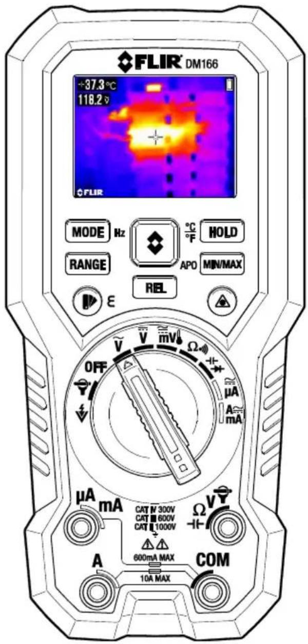
1. ADVISORIES 4
1.1 Copyright 4
1.2 Quality Assurance 4
1.3 Documentation 4
1.4 Disposal of Electronic Waste 4
2. SAFETY 5
3. INTRODUCTION 7
3.1 Key Features 7
4. METER DESCRIPTION AND REFERENCE GUIDE 8
4.1 Front and Back Meter Descriptions 8
4.2 Function Switch Positions 9
4.3 Function Buttons 10
4.3.1 MODE/Hz Button Sequence of Operations 10
4.4 Display Icons and Status Indicators 11
5. METER POWER 12
5.1 Powering the Meter 12
5.2 Intelligent Auto Power OFF (APO) 12
6. MULTIMETER OPERATION 13
6.1 Auto/Manual Range Modes 13
6.2 Probe Connection Alert 13
6.3 Out of Range Warning (OL) 14
6.4 Data (Display) Hold 14
6.5 MIN-MAX-AVG Mode 14
6.6 Relative Mode 14
6.7 Test Lead Holder Accessory 14
6.8 Voltage (AC/DC), VFD, and Frequency (Hz) Measurements 15
6.9 Non-Contact Voltage Detector 16
6.10 Resistance Measurements 17
6.11 Continuity Test 18
6.12 Diode Test 18
6.13 Capacitance Measurements 19
6.14 Type K Temperature Measurements 20
6.15 Current and Frequency Measurements (A, mA, μA) 20
6.15.1 Test Lead Current Measurements (A, mA, and A) 20
6.15.2 FLEX Clamp Adaptor Current and Frequency Measurements 22
7. IGM ^TM THERMAL IMAGER OPERATION 23
7.1 IGM ^TM (Infrared Guided Measurements) Basics 23
7.1.1 Thermal Image Display Description (refer to Fig. 7-1 for the list below) 23
7.1.2 Thermal Imager Operation 23
7.2 Using the Multimeter in the IGM ^TM mode 25
7.3 Emissivity Factors for Common Materials 25
7.4 Infrared Energy and Thermal Imaging Overview 26
8. MAINTENANCE 27
8.1 Cleaning and Storage 27
8.2 Battery Replacement 27
8.3 Fuse Replacement 27
8.4 Disposal of Electronic Waste 27
9. SPECIFICATIONS 28
9.1 General specifications 28
9.2 Thermal Imaging Specifications 30
9.3 Electrical Specifications 30
10. TECHNICAL SUPPORT 34
11. WARRANTIES 35
1.1 Copyright
© 2017, FLIR Systems, Inc. All rights reserved worldwide. No parts of the software including source code may be reproduced, transmitted, transcribed or translated into any language or computer language in any form or by any means, electronic, magnetic, optical, manual or otherwise, without the prior written permission of FLIR Systems. The documentation must not, in whole or part, be copied, photocopied, reproduced, translated or transmitted to any electronic medium or machine readable form without prior consent, in writing, from FLIR Systems.
Names and marks appearing on the products herein are either registered trademarks or trademarks of FLIR Systems and/or its subsidiaries. All other trademarks, trade names or company names referenced herein are used for identification only and are the property of their respective owners.
1.2 Quality Assurance
The Quality Management System under which these products are developed and manufactured has been certified in accordance with the ISO 9001 standard.
FLIR Systems is committed to a policy of continuous development; therefore, we reserve the right to make changes and improvements on any of the products without prior notice.
1.3 Documentation
To access the latest manuals and notifications, go to the Download tab at: http://support.flir.com. It only takes a few minutes to register online. In the download area you will also find the latest releases of manuals for our other products, as well as manuals for our historical and obsolete products.
1.4 Disposal of Electronic Waste
As with most electronic products, this equipment must be disposed of in an environmentally friendly way, and in accordance with existing regulations for electronic waste.
Please contact your FLIR Systems representative for more details.
Safety Notes
- Before operating the device, you must read, understand, and follow all instructions, dangers, warnings, cautions, and notes.
- FLIR Systems reserves the right to discontinue models, parts or accessories, and other items, or to change specifications at any time without prior notice.
- Remove the batteries if the device is not to be used for an extended period of time.

Warning Statements
- Do not operate the device if you do not have the correct knowledge. Incorrect operation of the device can cause damage, shock, injury or death to persons.
- Do not start a measuring procedure before you have set the function switch to the correct position. Failure to do so can cause damage to the instrument and can cause injury to persons.
- Do not change to the resistance mode when measuring voltage. This can cause damage to the instrument and can cause injury to persons.
- Do not measure the current on a circuit when the voltage increases to more than 1000 V. This can cause damage to the instrument and can cause injury to persons.
- You must disconnect the test leads from the circuit under test before you change the range. Failure to observe this warning can damage the instrument and cause bodily injury.
- Do not replace the batteries before you remove the test leads. This can cause damage to the instrument and can cause injury to persons.
- Do not use the device if the test leads and/or the device show signs of damage. Injury to persons can occur.
- Be careful performing measurements if the voltages are > 25 VAC rms or 35 VDC. There is a risk of shock from these voltages. Injury to persons can occur.
- Do not do diode, resistance or continuity tests before you have removed the power from capacitors and other devices under test. Injury to persons can occur.
- Be careful when performing voltage checks on electrical outlets. These checks are difficult because of the uncertainty of the connection to the recessed electrical contacts. You must not rely solely on this device when determining if the terminals are not “live”. There is a risk of electrical shock. Injury to person can occur.
- Do not touch expired/damaged batteries without gloves. Injury to persons can occur.
- Do not cause a short circuit of the batteries. This can cause damage to the instrument and can cause injury to persons.
- Do not put the batteries into a fire. Injury to persons can occur.
- Use extreme caution when the laser pointer is on.
- Do not point the beam toward anyone's eye or allow the beam to strike the eye from a reflective surface.
- Do not use the laser near explosive gases or in other potentially explosive areas.
• Refer to the CAUTION statement label (shown below) for critical safety information.
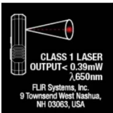
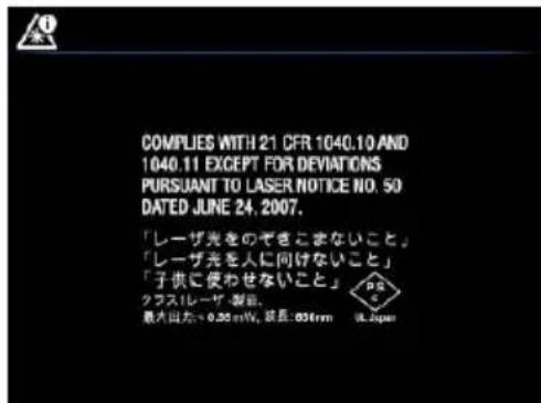
Note: The manufacturer's address label is located inside the battery compartment.
Cautions
Do not use the device in a manner not specified by the manufacturer. This can cause damage to the protection provided.
 | This symbol, adjacent to another symbol or terminal, indicates that the user must refer to the user manual for further information. |
 | This symbol, adjacent to a terminal, indicates that, under normal use, hazardous voltages may be present. |
 | Double insulation. |

UL listing is not an indication or a verification of the accuracy of the meter
3. Introduction
Thank you for selecting the FLIR DM166 True RMS Digital MultiMeter with IGM ^TM (Infrared Guided Measurement) Thermal Imaging. The DM166 can measure voltage up to 600V AC/DC and includes a VFD function (low pass filter). The thermal imager measures surface temperature, offers adjustable emissivity, and features a laser pointer and cross hairs for precise targeting. This device is shipped fully tested and calibrated and, with proper use, will provide years of reliable service.
3.1 Key Features
- 6000 count 2.4" digital TFT display, 320x240 pixels.
- IGM™ Infrared imager with selectable color palette, laser pointer, cross hairs targeting, and adjustable emissivity measures surface temperature
- Thermal imager (80x60 pixels) offers a 30:1 distance-to-spot ratio and a 50^ × 38.6^ field-of-view
- DMM measures AC/DC Voltage (V, mV), AC/DC Current (A, mA, μA), Frequency, Resistance, Continuity, Diode, Capacitance, and Type-K Temperature
• Built-in non-contact voltage detector (NCV) - Flex Clamp adaptor direct input
• Automatic and Manual ranging - Input over-voltage warning (OL)
- Input warning when test leads are incorrectly connected to meter
• MIN-MAX-AVG memory - Relative offset mode
- Variable-frequency drive 'VFD' feature (low-pass filter)
- Data (Display) Hold
- Intelligent Auto Power OFF (APO), customizable
• Safety Category Rating: CAT IV-300V, CAT III-600V. - Equipped with batteries, test leads, pouch, and Quick Start booklet.
4.1 Front and Back Meter Descriptions
- NCV sensor
- LCD display
- MODE/Hz button
- RANGE button
- Palette/Emissivity button
- Function Switch
- Positive (+) Probe Input Jack for A/mA (Current)
- Positive (+) Probe Input Jack for Amps (Current)
- COM (-) Probe Input Jack
- Positive (+) Probe Input Jack for all inputs except Amps, mA, and A
- Relative (REL) button
- Laser pointer ON/OFF button
- MIN-MAX/APO button
- HOLD/Temperature units button
-
Thermal Image mode button
-
Laser lens
- Thermal imaging lens
- Test Lead holder mounts
- Tripod mount
- Tilt stand
- Battery/Fuse compartment
- Battery/Fuse door lock
Fig. 4-1 Front View
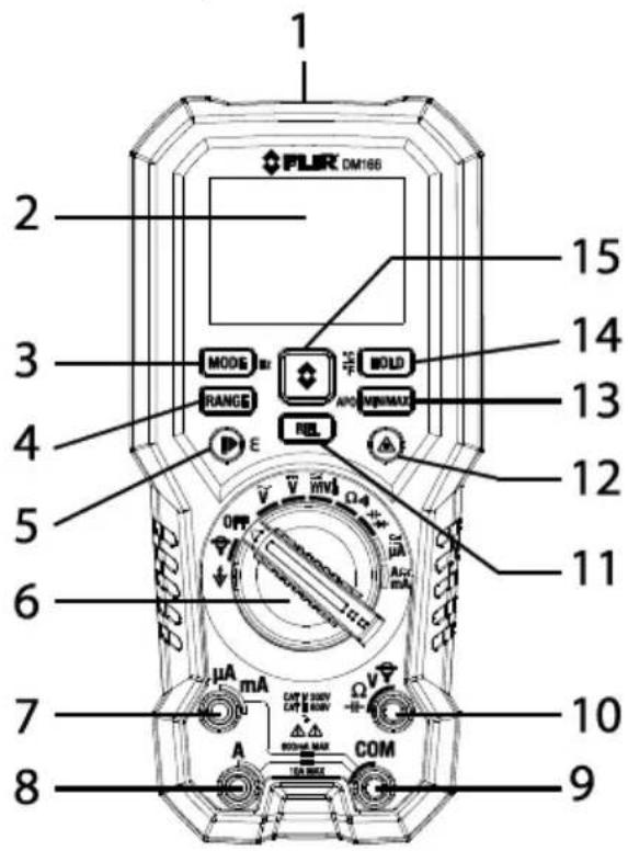
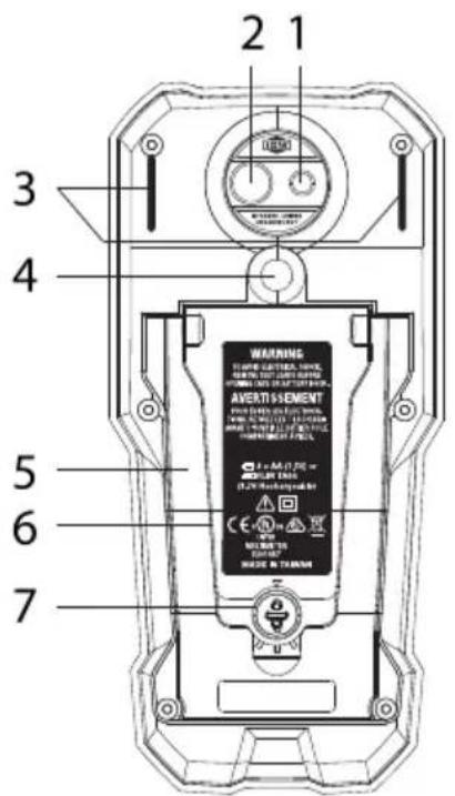
Fig. 4-2 Rear View
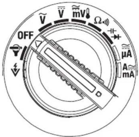
4.2 Function Switch Positions
| [W65G] | Detect AC voltage through the non-contact sensor at the top of the meter |
 | FLEX Direct: Auxiliary channel for use with optional Flexible Current clamp or standard clamp adaptors when >600A measurements are required. In this mode, the meter will display true rms ACA measurements from the connected device. Long press MODE to see the Frequency (Hz). |
 | Meter is switched OFF and in full power-saving mode. |
 | Measure AC voltage (V) through the probe inputs. Use the MODE button to select the VFD (low pass filter) function |
 | Measure DC voltage (V) through the probe inputs. |
 | Measure low voltage (mV) through the probe inputs. Use the MODE button to select AC/DC milli-volts.Measure temperature through the probe inputs using a thermocouple adaptor. Use the MODE button to select temperature. |
 | Measure resistance, continuity (use MODE button to toggle function). |
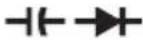 | Measure capacitance, or diode through the probe inputs. Use the MODE button to select the desired function. |
 | Measure μA current through the probe inputs. Use the MODE button to select AC or DC. |
 | Measure current through the probe inputs (A or mA). Use the MODE button to select AC or DC. |
Fig. 4-3 Rotary Function Switch
4.3 Function Buttons
| MODE Hz | Short press to toggle VFD on/off in AC Voltage mode or to toggle functions at a two-function switch position. Long press to view Frequency (Hz) in AC modes. Short press to step through AC/DC mV, and temperature when the function switch is set to the mV/Temp position. See Section 4.3.1, MODE Button Sequence of Operations. |
| RANGE | From Auto range mode, short press to select Manual range mode.In Manual mode, short press to change range; long press to return to Auto range. |
 | In thermal image mode, short press to select a color palette.Long press to open the emissivity adjustment menu, then short press to select emissivity value and long press to exit. |
| REL | Short press to enable/disable Relative mode. |
 | Short press to activate the Thermal Imager. Short press again to clear image of all text/icons. Short press a third time to exit the Thermal Imager mode. |
 | Press and hold to activate laser pointer. Release button to deactivate. |
| APO MIN/MAX | Short press to switch ON/OFF the MIN-MAX-AVG display.Long press to open the Auto Power OFF (APO) settings menu, then short press to select APO time and long press to exit. |
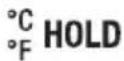 | Short press freezes/unfreezes display (DMM or thermal image mode).Long press toggles °C and °F temperature units in Thermal Image mode only. |
4.3.1 MODE/Hz Button Sequence of Operations
| Measurement | MODE/Hz button sequence of operations |
 | ACA < > Frequency (long button press) |
 | ACV < > Frequency (long press) |
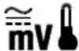 | AC mV > DC mV > °C > °F (short press)AC mV < > Frequency (long press) |
| [7T97] | Resistance < > Continuity (short press) |
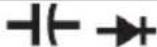 | Capacitance < > Diode (short press) |
 | ACμA < > DCμA (short press) |
 | AC < > DC (short press); ACA/ACmA < > Frequency (long press) |
4.4 Display Icons and Status Indicators
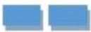 | For the non-contact voltage detector, the display bars and beeper represent the strength of the sensed voltage. Number of bars and beeper rate increase relative to voltage strength. |
 | Low sensitivity mode for non-contact voltage detector (80~1000V range). Use the RANGE button to toggle Hi/Lo setting. |
 | High sensitivity mode for non-contact voltage detector (20~1000V range). Use the RANGE button to toggle Hi/Lo setting. |
 | MAX reading displayed (available in DMM and Thermal Image modes) |
 | MIN reading displayed (available in DMM and Thermal Image modes) |
 | AVG reading displayed (available in DMM and Thermal Image modes) |
 | Auto range mode |
 | VFD (low pass filter) |
 | Data (display) HOLD for DMM and Thermal Image mode |
 | Relative mode (available in DMM and Thermal Image mode) |
| [THG] | Emissivity setting |
 | Battery status |
| [TS4W] | AC current or voltage |
| [DHW] | DC current or voltage |
 | Flex Clamp or standard clamp adaptor direct input |
 | Continuity mode |
 | Resistance mode |
 | Diode test mode |
 | Capacitance mode |
| [xwcs] | External Type K Thermocouple probe mode |
 | Temperature units |
5. Meter Power
5.1 Powering the Meter
- Set the function switch to any position to switch on the meter.
- If the battery indicator shows that the battery voltage is low, if a Low Battery warning screen appears, or if the meter does not power on, replace the batteries in the rear compartment. See Section 8.2, Battery Replacement. If using the Model TA04 charging system, please recharge the battery pack.
5.2 Intelligent Auto Power OFF (APO)
The meter enters sleep mode after a programmable period of inactivity, to customize this setting:
- Long press the APO button to open the APO menu
- Short press the APO button to step to the desired APO time or to OFF
- Long press the APO button to exit
- The last APO selection saved becomes the default APO time
-
The DM166 has an ‘intelligent’ APO feature where the meter will not power down if any of the following conditions exist:
-
Rotary switch or push button is operated
• Significant measurement > 8.5% of ranges
• Non-OL readings for Resistance, Continuity or Diode function
• Non-zero readings for Hz function
• Electric field signal present for NCV function
6. MultiMeter Operation
Caution: Before operating the device, you must read, understand, and follow all instructions, safety warnings, cautions, and notes.
Caution: When the meter is not in use, the function switch should be set to the OFF position.
Caution: When connecting the probe leads to the device under test, connect the COM (negative) lead before connecting the positive lead. When removing the probe leads, remove the positive lead before removing the COM (negative) lead.
6.1 Auto/Manual Range Modes
In Auto range mode, the meter automatically selects the most appropriate measurement scale. In Manual range mode, the user can adjust the range (scale). Auto range mode is the default mode of operation.
- To use Manual range, short press the RANGE button to enter the manual range mode, and short press again until the desired range appears.
- To return to the Auto range mode, long press the RANGE button until the Auto Range indicator appears.
6.2 Probe Connection Alert
When the probe leads are not plugged into the correct jacks for the measurement selected by the function switch, a display alert is shown and the beeper sounds. The warning shown in Figure 6-1, below left, appears when a test lead is plugged into the 'A' or 'μA/mA' input terminals with the rotary switch set to any function other than 'μA', 'mA', or 'A'. The warning shown in Figure 6-1, below right, appears when the test lead is plugged into the 'A' input terminal with the rotary switch set to the 'μA' terminal. In these cases, switch the meter off and correctly connect the test leads before attempting to make measurements.
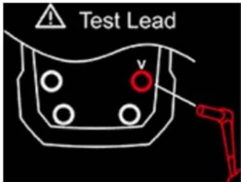

Fig. 6-1 Probe Connection Alert Screens
6.3 Out of Range Warning (OL)
If the input is outside the selected range in Manual mode, or if the signal has exceeded the maximum input in Auto range mode, 'OL' appears.
6.4 Data (Display) Hold
In Hold mode, the displayed reading freezes (DMM mode) or the thermal image freezes (Thermal Image mode). To enter/exit Hold mode, short press the Hutton. The indicator appears in the Hold mode.
6.5 MIN-MAX-AVG Mode
Short press the MIN/MAX button to start recording/viewing the lowest ↓, highest ↑, and average readings. Each time a memory display is updated the meter beeps. Short press MIN/MAX to return to the normal operating display.
6.6 Relative Mode
In Relative mode, you can compare measurements to a stored reference. For example, if the stored reference value is 10VDC and you take a measurement of 50VDC, the meter will display 40VDC (50V actual minus the 10V reference).
- Take a measurement and short press the REL button to store the reading (stored reading appears on the lower right corner of the display).
- Now, subsequent measurements will display 'relative' to the stored reference.
- Short press REL to return to the normal operating mode.
6.7 Test Lead Holder Accessory
Connect the test lead holder accessory (optional) to the two slots on the back of the meter (item 3 in Fig. 4-2) and to the tripod mount (item 4 in Fig. 4-2). The test lead holder is ergonomic and protects the thermal imaging and laser pointer lenses.
6.8 Voltage (AC/DC), VFD, and Frequency (Hz) Measurements
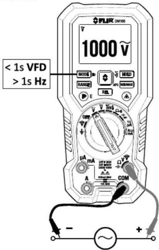
Fig. 6-2(a) AC Voltage/HZ Measurements
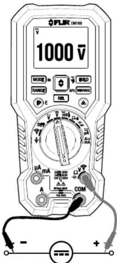
- Set the function switch to one of the following positions:
- (VDC) or (VAC) for high voltage measurements. Short press MODE to switch to VFD mode for VAC measurements. Press again to exit. - (milli-volts) for low voltage measurements. Short press MODE to select AC or DC for milli-volt measurements.
-
The indicator appears for AC measurements. The indicator appears for DC measurements.
-
Insert the black probe lead into the negative COM terminal and the red probe lead into the positive terminal.
-
Connect the probe leads in parallel to the part under test.
-
Read the measured voltage value on the display. The meter defaults to Auto Range mode. To use Manual Range mode: short press the Range button or refer to Section 6.1, Auto/Manual Range Modes.
-
If 'OL' appears, the signal being measured is out of the range of the meter's capability. In this case, stop the test immediately and review the application.
-
Short press the HOLD button to freeze/unfreeze the displayed reading.
-
To view the Frequency (Hz) of the measured AC voltage, long press the Hz button. Long press again to return to the voltage measurement.
-
For additional functionality, refer to Section 6.5, MIN-MAX-AVG Mode and Section 6.6, Relative Mode.
Fig. 6-2(b) DC Voltage Measurements
6.9 Non-Contact Voltage Detector
Warning: For safety, always test the voltage detector on a known live circuit before using the voltage detector on unknown voltage potentials.
- Set switch to the NCV ↓ position. See Figure 6-3.
- Be sure to remove the test leads from the meter.
- Short press the RANGE button to toggle the Hi (20\~1000V) and Lo (80\~1000V) sensitivity modes.
- Position the top of the meter close to a source of voltage.
- When the meter detects a voltage, it beeps and displays a blue bar animation. The tone rate and the bar number will increase relative to the detected voltage.
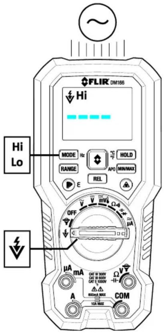
Fig. 6-3 Non-Contact Voltage Detector
6.10 Resistance Measurements
Warning: Do not test resistance/continuity before removing power from capacitors and other devices under test during a measurement. Injury to persons can occur.
- Refer to Fig. 6-4. Set the function switch to the resistance position.
- Short press MODE to step to the resistance mode.
- Insert the black probe lead into the negative COM terminal and red probe lead into positive terminal.
-
Touch the tips of the probe across the circuit or component under test.
-
Read the resistance value on the display. The meter defaults to Auto Range mode. To use Manual mode short press the RANGE button or refer to Section 6.1, Auto/Manual Range Modes.
-
If 'OL' appears, the signal is out of range. In this case, stop the test immediately and review the application.
-
Short press the HOLD button to freeze/unfreeze the displayed reading.
-
For additional functions, see Section 6.5, MIN-MAX-AVG Mode and Section 6.6, Relative Mode.
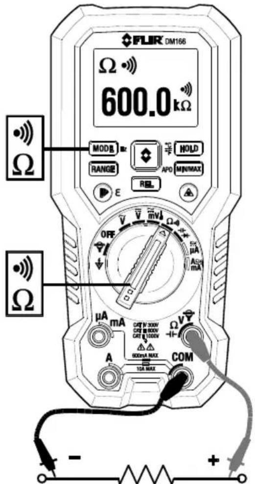
Fig. 6-4 Resistance and Continuity Measurements
6.11 Continuity Test
Warning: Do not perform continuity tests before removing the power from capacitors and other devices under test during a measurement. Injury to persons can occur.
- Refer to Fig. 6-4. Set the function switch to the continuity position.
- Short press the MODE button to select continuity if necessary ••••
- Insert the black probe lead into the negative COM terminal and the red probe lead into the positive terminal.
-
Touch the tips of the probe across the circuit or component under test.
-
If the resistance is < 30 the meter beeps
- If the resistance is >480 the meter will not beep
- If the resistance is >30 but < 480 the beep stops at an unspecified point
6.12 Diode Test
Warning: Do not perform diode tests before removing the power to the diode or other devices under test during a measurement. Injury to persons can occur.
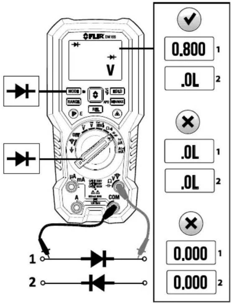
- Set the function switch to the diode position. Short press the MODE button to select the diode test function → necessary.
- Insert the black probe lead into the negative COM terminal and the red probe
lead into the positive terminal.
- Touch probe tips across the diode or semiconductor junction under test in one polarity (direction) and then in the opposite polarity as shown in Fig. 6-5.
- If the reading is between 0.400 and 0.800V in one direction and OL (overload) in the opposite direction, the component is good. If the measurement is 0V in both directions (shorted) or OL in both directions (open), the component is bad.
Fig. 6-5 Diode Test
6.13 Capacitance Measurements
Warning: Do not perform capacitance tests before removing power to the capacitor or other devices under test during a measurement. Injury to persons can occur.
- Set the function switch to the capacitance position.
- Short press the MODE button to select the capacitance measurement if necessary. The F (Farad) unit of measure appears.
-
Insert the black probe lead into the negative COM terminal and the red probe lead into the positive terminal.
-
Touch the tips of the probe across the part under test.
-
Read the capacitance value on the display. Short press the HOLD button to freeze/unfreeze the displayed reading.
-
For additional functionality, refer to Section 6.5, MIN-MAX-AVG Mode and Section 6.6, Relative Mode.
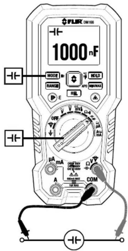
Fig. 6-6 Capacitance Measurements
Note: For very large capacitance values, it may take several minutes for the measurement to settle and the final reading to stabilize.
6.14 Type K Temperature Measurements
-
Set the function to the Temperature position.
-
Short presses of the MODE button step to the °F or °C temperature mode.
-
While observing polarity, insert the thermocouple adapter into the negative COM terminal and the positive terminal.
-
Touch the tip of the thermocouple to a part under test or hold the thermocouple in the surrounding air. Wait until the reading stabilizes before moving the thermocouple and recording the reading.
-
Read the temperature value on the display. Short press the HOLD button to freeze/unfreeze the displayed reading.
-
To avoid electrical shock, disconnect the thermocouple adapter before turning the function switch to another position.
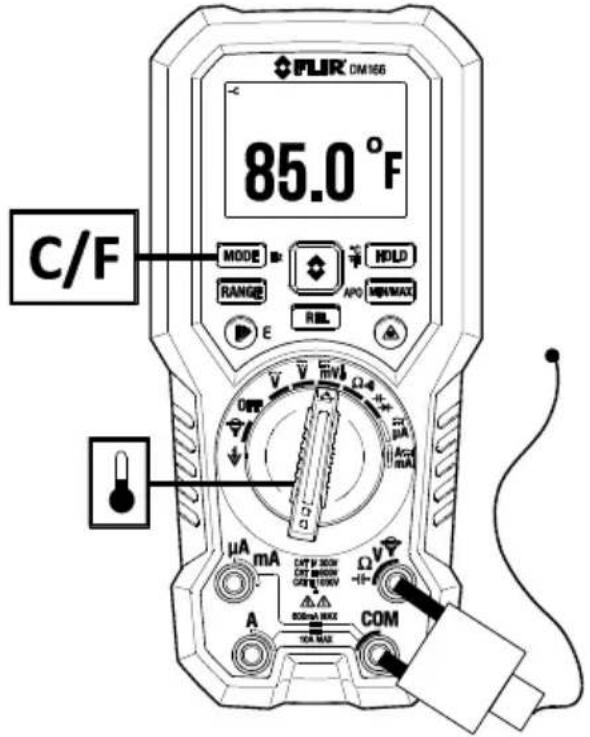
Fig. 6-7 Temperature Measurements
6.15 Current and Frequency Measurements (A, mA, μA)
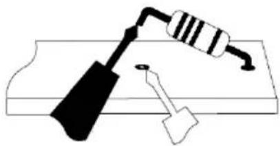
For test lead current measurements, disconnect the part under test and connect the test leads in series with the part, see Figure 6-8.
natural_image
Simple line drawing of a hammer and resistor on a base (no text or symbols)Fig. 6-8 Disconnected component
6.15.1 Test Lead Current Measurements (A, mA, and A)
-
For test-lead measurements: 'A' (amperes) and 'mA' (milli-amperes) set the function switch to the A≈ mA position. For 'μA' (microampere) measurements, set the function switch to the ≅ μA position.
-
Insert the black probe lead into the negative COM terminal and the red probe lead into one of the following positive terminals:
• A for high current measurements.
- mA for lower current measurements.
- A for micro-amp measurements
- If the test lead warning appears on the display and the meter beeps, turn meter power OFF and check the test lead connections to the meter. Do not attempt to use the meter when the alert is showing.
- Short press the MODE button to select AC or DC measurements.
• The indicator appears for AC measurements.
• The indicator appears for DC measurements.
-
Connect the probe leads in series with the part or circuit under test. Fig. 6-9 shows a typical setup example.
-
Read the current on the display. If 'OL' appears, the signal being measured is out of the range of the meter's capability. In this case, stop the test immediately and review the application.
- Short press the HOLD button to freeze/unfreeze the displayed reading.
- To see the frequency (Hz) of measured AC current, long press the Hz button; long press again to exit.
- For additional functionality, refer to Section 6.5, MIN-MAX-AVG Mode and Section 6.6, Relative Mode.
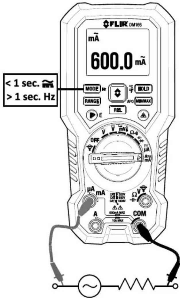
Fig. 6-9 Current Measurement example
6.15.2 FLEX Clamp Adaptor Current and Frequency Measurements
Connect a FLIR Flex Clamp Adaptor (Model TA72 or TA74, for example) or other clamp adaptor to the DM166 to display current measurements as detailed below:
- Turn the function dial to the 🔔 position.
- Connect a Clamp adaptor as shown in Fig. 6-10.
- Set the Range of the Flex Clamp Adaptor to match the range of the DM166.
- Short press the RANGE button to select the range of the DM166 (1, 10, or 100 mv/A, as shown in the upper left corner of the DM166 display).
- Operate the Flex Clamp meter (or other clamp adaptor) per the instructions provided with the Flex Clamp meter or other adaptor.
- Read the current measured by the Flex Clamp on the DM166 LCD. If 'OL' appears, the signal being measured is out of the range of the meter's capability. In this case, stop the test immediately and review the application.
- Short press the HOLD button to freeze/unfreeze the displayed reading.
- To see the frequency value for the measured current, long press the Hz button. Long press the button to return to the current measurement display.
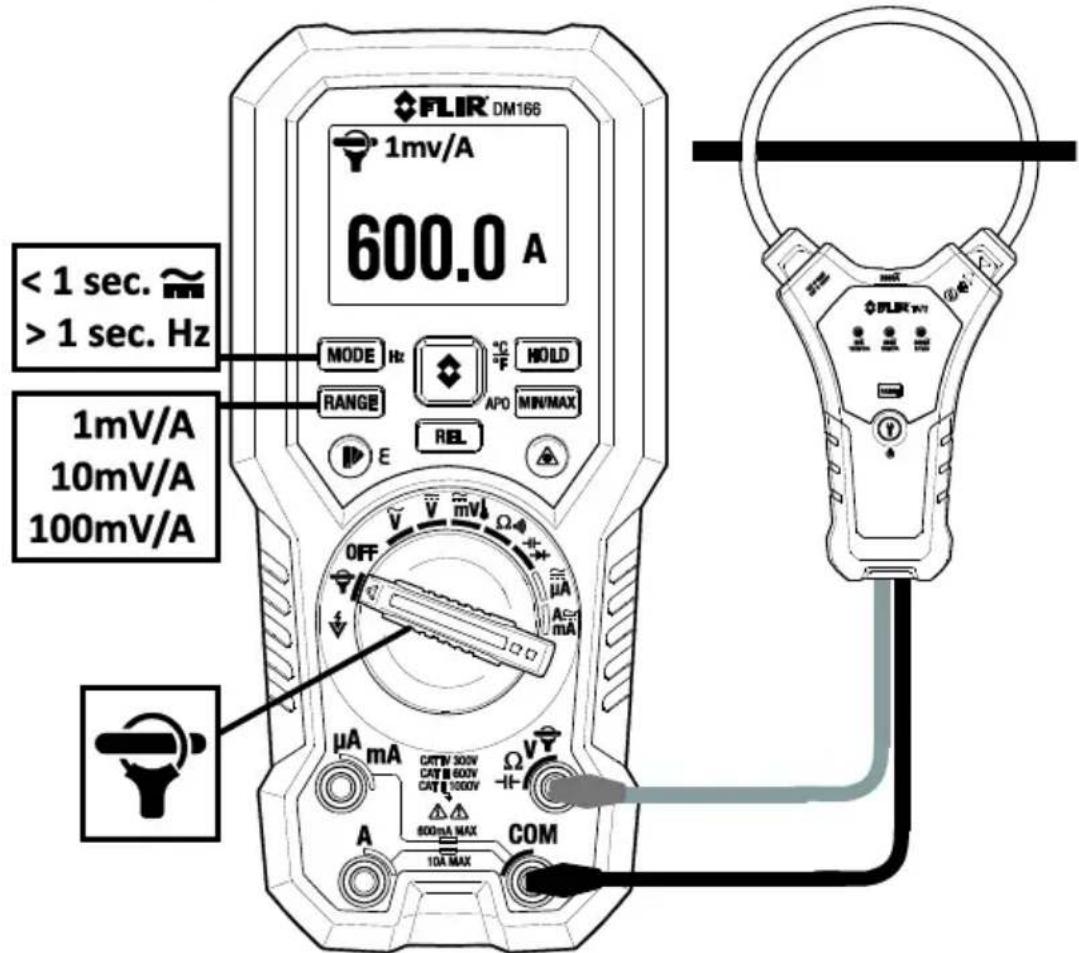
Fig. 6-10 FLEX Clamp Application
7.1 IGM ^TM (Infrared Guided Measurements) Basics
In the Thermal Imaging mode, the user can measure a targeted surface's temperature. The DM166 accomplishes this by detecting the energy emitted by the surface under test. The DM166 'sees' a thermal image of an area under test in the same manner as with a dedicated thermal imaging device. See Section 7.4, Infrared Energy and Thermal Imaging Overview for in-depth information. The DM166 laser pointer and cross hairs assist in targeting.
Press the IGM button to open the Thermal Imager. In Fig 7-1, the meter is set to color palette IRON. Short press the Palette/Emissivity button to select other colors.
Long press the Emissivity button to open the emissivity-setting menu. Press the Emissivity button to scroll to the desired setting, press and hold the emissivity button to exit. See Section 7.3, Emissivity Factors for Common Materials
7.1.1 Thermal Image Display Description (refer to Fig. 7-1 for the list below)
- Surface temperature measurement represents the temperature of the spot. Dashes display while the temperature reading stabilizes
- DMM measurement data
- Cross hairs for spot targeting
- Thermal image frame
- Icon area
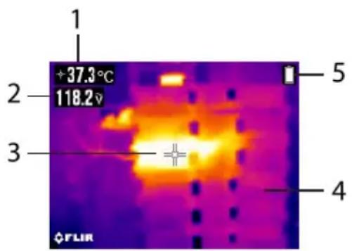
Fig. 7-1 IGM Display Example
7.1.2 Thermal Imager Operation
- Set the function switch to any position.
- Short press the IGM button to switch the Thermal Imager ON. Short press again to clear image of all text and icons. Short press again to exit the imager mode.
- With the Imager on, point the lens (back of meter) at the target.
- The display will show the temperature measurement in the upper left hand corner for the targeted area.
- Use the laser pointer and cross hairs for targeting. Press and hold the laser button to use the pointer; release the button to switch OFF the laser.
-
In the Thermal imaging mode, the meter continues to operate normally as a Multimeter; the electrical symbols appear on the left side of the display.
-
The Distance to Spot ratio for the imager is 30:1 meaning that the measurement spot is 30 times smaller than the distance the meter is from the spot (at a distance of 30", the meter 'sees' a target spot of 1"). See Fig. 7-2.
- The thermal imager's FOV (Field of View) is 50 degrees (top view) and 38.6 degrees (side view); see Fig. 7-3 (a) and (b).
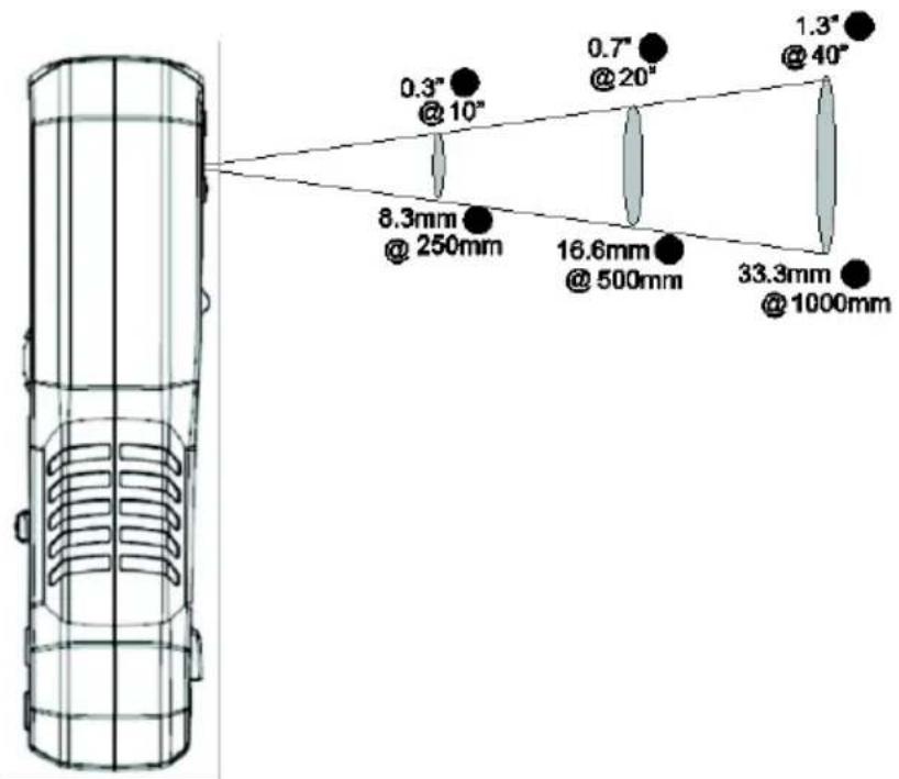
Fig. 7-2 Distance-to-Spot ratio 30:1
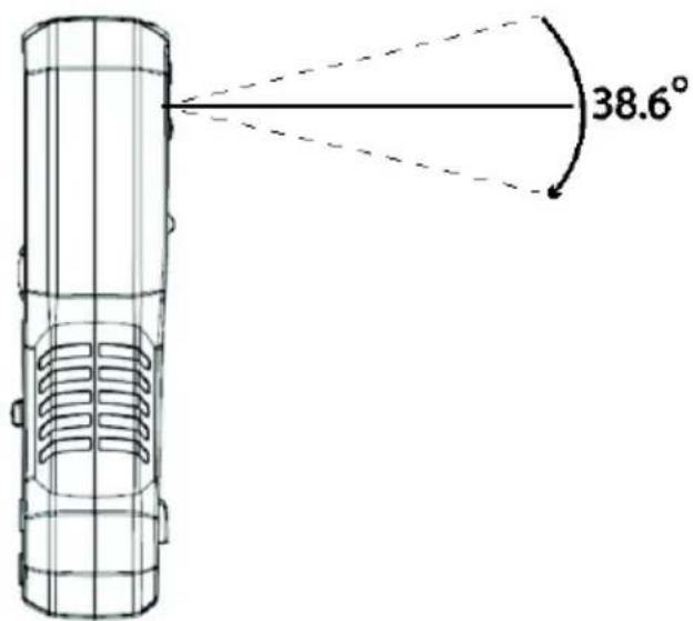
Fig. 7-3 (a) Field of View – side view
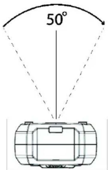
Fig. 7-3 (b) Field of View - top view
7.2 Using the Multimeter in the IGM ^TM mode
Use the Multimeter as described in Section 6, Multimeter Operation while the thermal imager is in use. Multimeter readings, icons, and operational modes 'Relative' and 'MIN-MAX-AVG' appear superimposed on the thermal image.
7.3 Emissivity Factors for Common Materials
| Material | Emissivity | Material | Emissivity |
| Asphalt | 0.90 to 0.98 | Cloth (black) | 0.98 |
| Concrete | 0.94 | Skin (human) | 0.98 |
| Cement | 0.96 | Leather | 0.75 to 0.80 |
| Sand | 0.90 | Charcoal (powder) | 0.96 |
| Soil | 0.92 to 0.96 | Lacquer | 0.80 to 0.95 |
| Water | 0.92 to 0.96 | Lacquer (matt) | 0.97 |
| Ice | 0.96 to 0.98 | Rubber (black) | 0.94 |
| Snow | 0.83 | Plastic | 0.85 to 0.95 |
| Glass | 0.90 to 0.95 | Timber | 0.90 |
| Ceramic | 0.90 to 0.94 | Paper | 0.70 to 0.94 |
| Marble | 0.94 | Chromium Oxides | 0.81 |
| Plaster | 0.80 to 0.90 | Copper Oxides | 0.78 |
| Mortar | 0.89 to 0.91 | Iron Oxides | 0.78 to 0.82 |
| Brick | 0.93 to 0.96 | Textiles | 0.90 |
7.4 Infrared Energy and Thermal Imaging Overview
A thermal imager generates an image based on temperature differences. In a thermal image, the hottest item in the scene appears as white and the coldest item as black. All other items are represented as a gray scale value between white and black. The DM166 also offers color images to simulate hot (lighter colors) and cold (darker colors) temperatures.
It may take some time to get used to the thermal imagery. Having a basic understanding of the differences between thermal and daylight cameras can help with getting the best performance from the DM166.
One difference between thermal and daylight cameras has to do with where the energy comes from to create an image. When viewing an image with an ordinary camera, there has to be some source of visible light (something hot, such as the sun or other lighting) that reflects off the objects in the scene to the camera. The same is true with human eyesight; the vast majority of what people see is based on reflected light energy. On the other hand, the thermal imager detects energy that is directly radiated from objects in the scene.
This is why hot objects such as parts on engines and exhaust pipes appear white, while the sky, puddles of water and other cold objects appear dark (or cool). Scenes with familiar objects will be easy to interpret with some experience.
Infrared energy is part of a complete range of radiation called the electromagnetic spectrum. The electromagnetic spectrum includes gamma rays, X-rays, ultraviolet, visible, infrared, microwaves (RADAR), and radio waves. The only difference is their wavelength or frequency. All of these forms of radiation travel at the speed of light. Infrared radiation lies between the visible and RADAR portions of the electromagnetic spectrum.
The primary source of infrared radiation is heat or thermal radiation. Any object that has a temperature radiates in the infrared portion of the electromagnetic spectrum. Even objects that are very cold, such as an ice cube, emit infrared. When an object is not quite hot enough to radiate visible light, it will emit most of its energy in the infrared. For example, hot charcoal may not give off light, but it does emit infrared radiation, which we feel as heat. The warmer the object, the more infrared radiation it emits.
Infrared imaging devices produce an image of invisible infrared or “heat” radiation that is unseen by the human eye. There are no colors or “shades” of gray in infrared, only varying intensities of radiated energy. The infrared imager converts this energy into an image that we can interpret.
The FLIR Infrared Training center offers training (including online training) and certification in all aspects of thermography: http://www.infraredtraining.com/.
8.1 Cleaning and Storage
Wipe the housing with a damp cloth as needed. Use a high quality lens wipe to remove dirt or smudges from the meter lenses and display window. Please do not use abrasives or solvents to clean the meter housing, lenses, or display window. If the meter is to be stored for an extended period, remove the batteries and store them separately.
8.2 Battery Replacement
The Battery symbol flashes with no ‘bars’ when the battery voltage has reached a critical level. The meter displays readings within specifications while the low battery indicator is on and powers off before it displays an out of tolerance reading.
WARNING: To avoid electrical shock, disconnect the meter from any connected circuits, remove the test leads from the meter terminals, and set the function switch to the OFF position before attempting to replace the batteries.
- Remove the battery cover (attached to tilt stand) by first unlocking it. To do so, use a flat-head screwdriver to move the lock/unlock screw to the unlocked position.
- Remove the battery cover and replace the three-1.5V 'AA' batteries observing correct polarity.
- If using the Model TA04 rechargeable lithium-polymer battery system, please recharge the rechargeable battery.
- Secure the battery compartment cover before use.
8.3 Fuse Replacement
Access the two fuses by first unlocking the battery/fuse compartment cover (attached to the tilt stand). To do so, use a flat-head screwdriver to move the locking/unlocking screw to the unlocked position. Then remove the two small Phillips-heads screws to open the fuse compartment. The fuse ratings are:
8.4 Disposal of Electronic Waste
As with most electronic products, this equipment must be disposed of in an environmentally friendly way, and in accordance with existing regulations for electronic waste. Please contact your FLIR Systems representative for more details.
9.1 General specifications
Display: 3-5/6 digits 6,000 counts
Update Rate: Five (5) per second nominal
Operating Temperature: 14 \~ 122°F (-10°C \~ 50°C)
Relative Humidity: Maximum relative humidity 80% for temperature up to 87.8°F (31°C) decreasing linearly to 50% relative humidity at 122°F (50°C)
Altitude: Operating below 6560 ft (2000m)
Storage Temperature: -4°F \~ 140°F (-20°C \~ 60°C), < 80% R.H. (with battery removed)
Temperature Coefficient: Nominal 0.15 x (specified accuracy)/ °C @ 14°F \~ 64.4°F (-10°C \~ 18°C) or 82.4°F \~ 122°F (28°C \~ 50°C), or as otherwise specified
Sensing: True RMS sensing
Pollution Degree: 2
Safety: Certified per IEC/UL/EN61010-1 Ed. 3.0, IEC/UL/EN61010-2-030 Ed. 1.0, IEC/UL/EN61010-2-033 Ed. 1.0, IEC/UL/EN61010-031 Ed. 1.1 and the corresponding CAN/CSA-C22.2 regulations to
Measurement Categories:
CAT III 600V and CAT IV 300V AC & DC
Transient Protection: 6.0kV (1.2/50μs surge)
E.M.C.: Meets EN61326-1:2013; In an RF field of 3V/m:
Temperature function not specified
Ohm function: Total Accuracy = Specified Accuracy + 15 digits
Other functions: Total Accuracy = Specified Accuracy
Performance above 3V/m not specified
Overload Protection:
μA & mA: 0.4A/1000V DC/AC rms, IR 30kA, F fuse or better
A: 11A/1000V DC/AC rms, IR 20kA, F fuse or better
V & Auto V: 1100V DC/AC rms
mV, Ohm, & others: 1000V DC/AC rms
Drop protection: 9.8'(3m)
Power Supply: 3 x 1.5 V AA alkaline or Li/FeS _2 lithium batteries or optional Model TA04 lithium polymer rechargeable battery system
Power Requirements for thermal imager:
- Battery Type: Alkaline 'AA' Battery x 3
Battery Life: approximately 12 hours - Battery Type: Energizer L91 Lithium (Li/FeS _2 ) 'AA' Battery x 3
Battery Life: approximately 22 hours - Optional Rechargeable Battery: Li-Polymer; FLIR PN: TA04-KIT
Battery Life: approximately 22 hours
Power Consumption (typical): 160mA
APO Consumption (typical): 200μA
APO Timing: Five (5) minutes (default), 10 minutes, 20 minutes & OFF selectable
APO counter reset for DMM mode:
- Rotary switch or push button operations
• Significant measuring readings of above 8.5% of ranges
• Non-OL readings for Resistance, Continuity or Diode function
• Non-zero readings for Hz function
• Electric field signal present for EF function
APO counter reset for Thermal Imager mode:
Rotary switch or push button operations
Accessories: Test lead pair, Batteries, Quick Start manual, Pouch
Calibration Cycle: One year
Weight: 15.1 oz (428.3g)
Dimensions: (L x W x H) 7.5 x 3.4 x 1.9 in. (190 x 86.4 x 48.3mm)
| CAT | Application Field |
| I | Circuits not connected to mains. |
| II | Circuits directly connected to a low-voltage installation. |
| III | Building installation. |
| IV | Source of the low-voltage installation. |
9.2 Thermal Imaging Specifications
IR Temperature Range 14 \~ 302°F (-10 \~ 150°C)
IR Temperature Resolution 0.1°C/F
Image Sensitivity < or equal to 150mK (0.15°C)
IR Temperature Accuracy ±9°F (±5°C) or ±5% (14\~302°F [-10 to 150°C]) whichever is greater
Emissivity 0.95 maximum (4 presets and a fine tuning feature)
Distance to Spot ratio 30:1
Response time 150ms
Spectral Response 8\~14um
Scanning type Continuous
Repeatability 0.5%
Image Detector Lepton
Display resolution 80 x 60 pixels
Field of View (FOV) 38.6 ° x 50°
Color Palettes Selectable: Iron, Rainbow, and Greyscale
Laser type Class 1
Laser power < 0.4mW
9.3 Electrical Specifications
*Accuracy is given as ± (% of reading + counts of least significant digit) or as otherwise specified at 73.4°F ±9°F (23°C ± 5°C), with relative humidity < 80%; AC Voltage & Current accuracies are specified from 1% to 100% of range, or as otherwise specified.
Maximum Crest Factor is <2:1 at full scale & <4:1 at half scale, and with frequency components within the specified frequency bandwidth for non-sinusoidal waveforms
Other AC Function notes:
- ACV and ACA are ac coupled, true RMS
- For all AC functions, the LCD displays 0 counts when the reading < 10 counts
Temperature Coefficient: Nominal 0.15 x (specified accuracy)/ °C @ 14°F \~ 64.4°F (-10°C \~ 18°C) or 82.4°F \~ 122°F (28°C \~ 50°C), or as otherwise specified
AC Voltage*
| RANGE and RESOLUTION | Accuracy |
| 50Hz ~ 60Hz | |
| 6.000V, 60.00V, 600.0V | 0.7% + 3d |
| 45Hz ~ 440Hz | |
| 6.000V, 60.00V, 600.0V | 2.0% + 3d |
Input Impedance: 10MΩ, 54pF nominal
VFD_ACV* (with Low Pass Filter)
| RANGE and RESOLUTION | Accuracy1) |
| 10Hz ~ 100Hz (fundamental) | |
| 600.0V, | 1.0% + 3d |
| 100Hz ~ 400Hz (fundamental) | |
| 600.0V, | 10% + 3d2) |
^1) Not specified for fundamental frequency > 400Hz
^2) Accuracy linearly decreases from 1% + 3d @100Hz to 10% + 3d @400Hz
ACmV*
| RANGE and RESOLUTION | Accuracy |
| 50Hz ~ 60Hz | |
| 60.00mV1)2), 600.0mV3) | 1.0% + 3d |
| 10Hz ~ 500Hz | |
| 60.00mV1)2), 600.0mV3) | 2.0% + 3d |
Input Impedance: 10MΩ, 54pF nominal
^1) Non-zero residual readings ≤ 5d may appear as a zero volt input (short-circuit) when battery indication is ≤ 25%
^2) Signal peak absolute values, including DC bias: < 130mV peak
^3) Signal peak absolute values, including DC bias: < 1300mV peak
DC Voltage
| RANGE and RESOLUTION | Accuracy |
| 60.00mV, 600.0mV, | 0.3% + 2d |
| 6.000V, 600.0V | 0.4% + 2d |
| 60.00V | 0.5% + 2d |
Input Impedance: 10MΩ, 54pF nominal
Ohm
| RANGE and RESOLUTION1) | Accuracy |
| 600.0Ω | 0.3% + 3d |
| 6.000kΩ,60.00kΩ, 600.0kΩ | 0.5% + 3d |
| 6.000MΩ2) | 0.9% + 2d |
| 60.00MΩ3)4)5) | 1.5% + 2d |
^1) Open Circuit Voltage: 1.6VDC typical
^2) Constant Test Current: 0.1 A Typical
^3) Constant Test Current: 0.01 A Typical
^4) 5%+20d @ >30MΩ,
^5) Unspecified @ ambient > 40°C
Audible Continuity Tester
| Continuity Threshold: Between 30Ω and 480Ω |
| Continuity ON Response Time: <15ms |
Capacitance
| RANGE and RESOLUTION | Accuracy |
| 20.00nF, 200.0nF | 1.5% + 8d |
| 2000nF, 20.00μF, 200.0μF | 1.5% + 2d |
| 2000μF | 2.0% + 2d |
| 10.00mF | 5.0% + 10d |
Accuracies stated for film capacitors (or better)
Diode Tester
| RANGE and RESOLUTION | Accuracy |
| 3.000V | 0.9% + 3d |
Test Current: 0.3mA typical
Open Circuit Voltage: < 3.2VDC typical
DC Current
| RANGE and RESOLUTION | Accuracy | Burden Voltage |
| 600.0 A^1) , 6000 A^1) | 1.0% + 3d | 0.1mV/ A |
| 60.00mA^1) , 600.0mA^1)^2) | 0.7% + 3d | 1.9mV/mA |
| 6.000A^3)^4) , 10.00A^3)^4)^5) | 0.04V/A |
1) A/mA DC accuracy is affected by extreme internal meter temperatures. For rated accuracies, allow linear proportional cool down intervals from 6 to 20 minutes after measuring currents from 3 to 10A continuously via A-input.
2) <400mA continuous; >400mA for <20 minutes ON per >5 minutes OFF
3) 10A continuous up to ambient 95^ (35°C); <15 minutes on per >5 minutes off @ 95\~122°F (35°C \~ 50°C)
4) >10A to 20A for <30 seconds ON per >5 minutes OFF
AC Current*
| RANGE and RESOLUTION | Accuracy | Burden Voltage |
| 45Hz ~ 440Hz | ||
| 600.0μA ^1) 2), 6000μA ^2) | 1.5% + 3d | 0.1mV/μA |
| 60.00mA ^1) 2), 600.0 mA ^2) 3) | 1.0% + 3d | 1.9mV/mA |
| 6.000A ^1) 4)5), 10.00A ^4) 5)6) | 0.04V/A | |
1) Non-zero residual readings ≤5d may appear as a zero ampere input when battery indication is ≤25%
2) A/mA DC accuracy is affected by extreme interior temperature of the meter. For rated accuracies, allow linear proportional cool down intervals from 6 to 20 minutes after measuring currents from 3 to 10A continuously via A-input.
3) <400mA continuous; >400mA for <20 minutes ON per >5 minutes OFF
4) 10A continuous up to ambient 35oC; <15 minutes ON per >5 minutes OFF @ 95\~122°F (35°C \~ 50°C)
5) >10A to 20A for <30 seconds ON per >5 minutes OFF
6) Unspecified @ <0.5A
Temperature
| RANGE and RESOLUTION | Accuracy 1) 2) 3) |
| -40.0 °C ~ 0.0 °C | 1% + 1.5 °C |
| 0.0 °C ~ 100.0 °C | 1% + 1 °C |
| 100.0 °C ~ 400.0°C | |
| -40.0 °F ~ 32.0 °F | 1% + 3 °F |
| 32.0 °F ~212.0 °F | 1% + 2 °F |
| 212.0°F ~ 752.0 °F |
1) Accuracies assume meter interior has the same temperature as the ambient (isothermal stage) for correct junction voltage compensation. Allow enough time to reach the isothermal stage for a significant change of ambient temperature. It can take up to an hour for changes >9^ F ( 5^ C).
2) Type-K thermocouple range & accuracy not included
3) For isothermal stage, allow linear proportional cool down intervals from 9 to 30 minutes after measuring currents from 3 to 10A continuously via A-input.
Line Frequency
| Function | Sensitivity (Sine RMS) | Range |
| 60mV, 600mV | 50mV | 10Hz - 50kHz |
| 6V | 5V | 10Hz - 50kHz |
| 60V | 10V | 10Hz - 50kHz |
| 600V | 50V | 10Hz - 1kHz |
| 600V VFD | 50V | 10Hz-400Hz |
| 600μA, 6000μA | 500μA | 10Hz - 5kHz |
| 60mA, 600mA | 50mA | 10Hz - 5kHz |
| 6A, 10A | 8A | 50Hz - 1kHz |
Accuracy: 0.03% + 2d
FLEX*
| RANGE and RESOLUTION | Accuracy |
| 50Hz ~ 400Hz | |
| 30.00A, 300.0A, 3000A | 2.0% + 3d |
Input Impedance: 10MΩ, 54pF nominal
Non-Contact Voltage EF-Detection
| Bar-Graph Indication | EF-H (Hi Sensitivity) | EF-L (Lo Sensitivity) | |
| DMM mode | IGM mode | Typical Voltage (Tolerance) | |
| -- | - | 20V (10V ~ 30V) | 80V (40V ~ 150V) |
| ---- | -- | 40V (20V ~ 60V) | 160V (80V ~ 300V) |
| ---- | --- | 80V (40V ~ 150V) | 320V (160V ~ 450V) |
| ---- | ---- | 160V (80V ~ 300V) | 640V (320V ~ 900V) |
| ---- | ---- | 320V (>320V) | 1000V (>950V) |
Indication: Bar-graph segments & audible beep tones proportional to the field strength
Detection Frequency: 50/60Hz
Detection Antenna: Top of meter
10. Technical Support
| Main Website | http://www.flir.com/test |
| Technical Support Website | http://support.flir.com |
| Technical support Email | TMSupport@flir.com |
| Service/Repair Support Email | Repair@flir.com |
| Support Telephone number | +1 855-499-3662 option 3 (toll-free) |
11. Warranties
11.1 FLIR Test & Measurement Imaging Product 10-year/10-year Warranty
Congratulations! You (the “Purchaser”) are now the owner of a world-class FLIR Imaging Test and Measurement product. A qualifying FLIR Imaging Test and Measurement product (the “Product”) purchased either directly from FLIR Commercial Systems Inc. and affiliates (FLIR) or from an authorized FLIR distributor that Purchaser registers on-line with FLIR is eligible for coverage under FLIR’s industry-leading 10-10 Limited Warranty, subject to the terms and conditions in this document. This warranty only applies to purchases of Qualifying Products (see below) purchased after September 2015 and only to the original Purchaser of the Product.
PLEASE READ THIS DOCUMENT CAREFULLY; IT CONTAINS IMPORTANT INFORMATION ABOUT THE PRODUCTS THAT QUALIFY FOR COVERAGE UNDER THE 10-10 LIMITED WARRANTY, PURCHASER'S OBLIGATIONS, HOW TO ACTIVATE THE WARRANTY, WARRANTY COVERAGE, AND OTHER IMPORTANT TERMS, CONDITIONS, EXCLUSIONS AND DISCLAIMERS.
- PRODUCT REGISTRATION. To qualify for FLIR's 10-10 Limited Warranty, the Purchaser must fully register the Product directly with FLIR on-line at www.flir.com WITHIN Sixty (60) DAYS of the date the Product was purchased by the first retail customer (the "Purchase Date"). PRODUCTS THAT ARE NOT REGISTERED ON-LINE WITHIN Sixty (60) DAYS OF THE PURCHASE DATE OR PRODUCTS WHICH DO NOT QUALIFY FOR THE 10-10 WARRANTY WILL HAVE A LIMITED ONE YEAR WARRANTY FROM THE DATE OF PURCHASE.
- QUALIFYING PRODUCTS. Upon registration, a list of thermal Imaging Test and Measurement Products that qualify for coverage under FLIR's 10-10 Warranty can be found at www.flir.com/testwarranty
- WARRANTY PERIODS. The 10-10 Limited Warranty has two separate periods of warranty coverage (the "Warranty Period"), depending on the Imaging Test and Measurement Product part:
Product components are warranted for a period of ten (10) years from the Purchase Date;
Thermal imaging sensor is warranted for a period of ten (10) years from the Purchase Date.
Any Product that is repaired or replaced under warranty is covered under this 10-10 Limited Warranty for one hundred eighty days (180) days from the date of return shipment by FLIR or for the remaining duration of the applicable Warranty Period, whichever is longer.
- LIMITED WARRANTY. In accordance with the terms and conditions of this 10-10 Limited Warranty, and except as excluded or disclaimed in this document, FLIR warrants, from the Purchase Date, that all fully registered Products will conform to FLIR's published Product specifications and be free from defects in materials and workmanship during the applicable Warranty Period. PURCHASER'S SOLE AND EXCLUSIVE REMEDY UNDER THIS WARRANTY, AT FLIR'S SOLE DISCRETION, IS THE REPAIR OR REPLACEMENT OF DEFECTIVE PRODUCTS IN A MANNER, AND BY A SERVICE CENTER, AUTHORIZED BY FLIR. IF THIS REMEDY IS ADJUDICATED TO BE INSUFFICIENT, FLIR SHALL REFUND PURCHASER'S PAID PURCHASE PRICE AND HAVE NO OTHER OBLIGATION OR LIABILITY TO BUYER WHATSOEVER.
- WARRANTY EXCLUSIONS AND DISCLAIMERS. FLIR MAKES NO OTHER WARRANTY OF ANY KIND WITH RESPECT TO THE PRODUCTS. ALL OTHER WARRANTIES, EXPRESS OR IMPLIED, INCLUDING BUT NOT LIMITED TO IMPLIED WARRANTIES OF MERCHANTABILITY, FITNESS FOR A PARTICULAR PURPOSE (EVEN IF PURCHASER HAS NOTIFIED FLIR OF ITS INTENDED USE FOR THE PRODUCTS), AND NON-INFRINGEMENT ARE EXPRESSLY EXCLUDED FROM THIS AGREEMENT.
THIS WARRANTY EXPRESSLY EXCLUDES ROUTINE PRODUCT MAINTENANCE, AND SOFTWARE UPDATES. FLIR FURTHER EXPRESSLY DISCLAIMS ANY WARRANTY COVERAGE WHERE THE ALLEGED NONCONFORMITY IS DUE TO NORMAL WEAR AND TEAR OTHER THAN SENSORS, ALTERATION, MODIFICATION, REPAIR, ATTEMPTED REPAIR, IMPROPER USE, IMPROPER MAINTENANCE, NEGLECT, ABUSE, IMPROPER STORAGE, FAILURE TO FOLLOW ANY PRODUCT INSTRUCTIONS, DAMAGE (WHETHER CAUSED BY ACCIDENT OR OTHERWISE), OR ANY OTHER IMPROPER CARE OR HANDING OF THE PRODUCTS CAUSED BY ANYONE OTHER THAN FLIR OR FLIR'S EXPRESSLY AUTHORIZED DESIGNEE.
THIS DOCUMENT CONTAINS THE ENTIRE WARRANTY AGREEMENT BETWEEN PURCHASER AND FLIR AND SUPERSEDES ALL PRIOR WARRANTY NEGOTIATIONS, AGREEMENTS, PROMISES AND UNDERSTANDINGS BETWEEN PURCHASER AND FLIR. THIS WARRANTY MAY NOT BE ALTERED WITHOUT THE EXPRESS WRITTEN CONSENT OF FLIR.
- WARRANTY RETURN, REPAIR AND REPLACEMENT. To be eligible for warranty repair or replacement, Purchaser must notify FLIR within thirty (30) days of discovering of any apparent defect in materials or workmanship. Before Purchaser may return a Product for warranty service or repair, Purchaser must first obtain a returned material authorization (RMA) number from FLIR. To obtain the RMA number Owner must provide an original proof of purchase. For additional information, to notify FLIR of an apparent defect in materials or workmanship, or to request an RMA number, visit www.flir.com. Purchaser is solely responsible for complying with all RMA instructions provided by FLIR including but not limited to adequately packaging the Product for shipment to FLIR and for all packaging and shipping costs. FLIR will pay for returning to Purchaser any Product that FLIR repairs or replaces under warranty.
FLIR reserves the right to determine, in its sole discretion, whether a returned Product is covered under warranty. If FLIR determines that any returned Product is not covered under warranty or is otherwise excluded from warranty coverage, FLIR may charge Purchaser a reasonable handling fee and return the Product to Purchaser, at Purchaser's expense, or offer Purchaser the option of handling the Product as a non-warranty return. FLIR shall not be responsible for any data, images or other information that may be stored on the returned Product which was not included in the Product at the time of purchase. It is Purchaser's responsibility to save any and all data prior to returning the Product for warranty service.
- NON-WARRANTY RETURN. Purchase may request that FLIR evaluate and service or repair a Product not covered under warranty, which FLIR may agree to do in its sole discretion. Before Purchaser returns a Product for non-warranty evaluation and repair, Purchaser must contact FLIR by visiting www.flir.com to request an evaluation and obtain an RMA. Purchaser is solely responsible for complying with all RMA instructions provided by FLIR including but not limited to adequately packaging the Product for shipment to FLIR and for all packaging and shipping costs. Upon receipt of an authorized non-warranty return, FLIR will evaluate the Product and contact Purchaser regarding the feasibility of and the costs and fees associated with Purchaser's request. Purchaser shall be responsible for the reasonable cost of FLIR's evaluation, for the cost of any repairs or services authorized by Purchaser, and for the cost of repackaging and returning the Product to Purchaser. Any non-warranty repair of a Product is warranted for one hundred eighty days (180) days from the date of return shipment by FLIR to be free from defects in materials and workmanship only, subject to all of the limitations, exclusions and disclaimers in this document.
Corporate Headquarters
FLIR Systems, Inc.
2770 SW Parkway Avenue
Wilsonville, OR 97070
USA
Telephone: +1 503-498-3547
Customer Support
Technical Support Website http://support.flir.com
Technical Support Email TMSupport@flir.com
Service and Repair Email Repair@flir.com
Customer Support Telephone +1 855-499-3662 option 3 (toll free)
Publication Identification No.: DM166-en-US
Release Version: AA
Release Date: October 2017
Language: en-US


- Thermal Imaging Digital MultiMeter with IGM™
- ADVISORIES 4
- SAFETY 5
- INTRODUCTION 7
- METER DESCRIPTION AND REFERENCE GUIDE 8
- METER POWER 12
- MULTIMETER OPERATION 13
- IGM TM THERMAL IMAGER OPERATION 23
- MAINTENANCE 27
- SPECIFICATIONS 28
- TECHNICAL SUPPORT 34
- WARRANTIES 35
- Copyright
- Quality Assurance
- Documentation
- Disposal of Electronic Waste
- Safety Notes
- Warning Statements
- Cautions
- Introduction
- Key Features
- Front and Back Meter Descriptions
- Function Switch Positions
- Function Buttons
- MODE/Hz Button Sequence of Operations
- Display Icons and Status Indicators
- Meter Power
- Powering the Meter
- Intelligent Auto Power OFF (APO)
- MultiMeter Operation
- Auto/Manual Range Modes
- Probe Connection Alert
- Out of Range Warning (OL)
- Data (Display) Hold
- MIN-MAX-AVG Mode
- Relative Mode
- Test Lead Holder Accessory
- Voltage (AC/DC), VFD, and Frequency (Hz) Measurements
- Non-Contact Voltage Detector
- Resistance Measurements
- Continuity Test
- Diode Test
- Capacitance Measurements
- Type K Temperature Measurements
- Current and Frequency Measurements (A, mA, μA)
- Test Lead Current Measurements (A, mA, and A)
- FLEX Clamp Adaptor Current and Frequency Measurements
- IGM TM (Infrared Guided Measurements) Basics
- Thermal Image Display Description (refer to Fig. 7-1 for the list below)
- Thermal Imager Operation
- Using the Multimeter in the IGM TM mode
- Emissivity Factors for Common Materials
- Infrared Energy and Thermal Imaging Overview
- Cleaning and Storage
- Battery Replacement
- Fuse Replacement
- Disposal of Electronic Waste
- General specifications
- Pollution Degree: 2
- Measurement Categories:
- Overload Protection:
- Thermal Imaging Specifications
- Electrical Specifications
- Other AC Function notes:
- Technical Support
- Warranties
- FLIR Test & Measurement Imaging Product 10-year/10-year Warranty
Brand : FLIR
Model : DM166
Category : Multimeter