
ZI-COM100-2V5 - Compressor Zipper - Free user manual and instructions
Find the device manual for free ZI-COM100-2V5 Zipper in PDF.


| Product Type | Air Compressor |
| Brand | Zipper |
| Model | ZI-COM100-2V5 |
| EAN | 9120039234243 |
| Power Supply | 230 V ~ 50 Hz |
| Max. Pressure | 8 bar (approx.) |
| Tank Capacity | 50 L (approx.) |
| Motor Power | 1.5 kW (approx.) |
| Oil Type | SAE 30 |
| Dimensions (L x W x H) | 800 x 400 x 700 mm (approx.) |
| Weight | 45 kg (approx.) |
| Sound Level | 97 dB(A) (approx.) |
| Safety Features | Pressure relief valve, thermal overload protection |
| Filter Type | Two air filters |
| Condensate Drain | Manual drain screw at bottom of tank |
| Regulated Output | Adjustable via pressure regulator |
| Warranty | 2 years amateur, 1 year professional |
| Spare Parts Availability | Original ZIPPER parts via online catalog |
Frequently Asked Questions - ZI-COM100-2V5 Zipper
User questions about ZI-COM100-2V5 Zipper
0 question about this device. Answer the ones you know or ask your own.
Ask a new question about this device
Download the instructions for your Compressor in PDF format for free! Find your manual ZI-COM100-2V5 - Zipper and take your electronic device back in hand. On this page are published all the documents necessary for the use of your device. ZI-COM100-2V5 by Zipper.
USER MANUAL ZI-COM100-2V5 Zipper
natural_image
Green ZIPPER air compressor with attached spray guns and hose, no visible text or symbols on main subjectCE
ZI-COM100-2V5
EAN: 9120039234243

16.1 Intended Use of the Machine.... 17
16.1.1 Technical Restrictions 17
16.1.2 Prohibited Use / Forseeable Misuse.... 17
16.2 User Requirements.... 17
16.3 Safety Devices.... 17
16.4 General Safety Instructions.... 18
16.5 Electrical Safety....18
16.6 Special Safety Instructions for that machine.... 18
16.7 Hazard Warnings.... 19
17 TRANSPORT 19
18 ASSEMBLY 20
18.1 Checking scope of delivery 20
18.2 Setting up the device.... 20
18.3 Assembly....20
19 START UP CHECKLIST 21
19.1 Oil-level check / refilling oil 21
19.2 Additional notes 21
19.3 Initial start up 21
20 OPERATION 22
20.1 Switching machine ON/OFF 22
20.2 Adjusting the output-pressure.... 22
20.3 Establishing the compressed air connection 22
21 MAINTENANCE 23
21.1 maintenance plan 23
21.1.1 Changing the air filter 23
21.1.1 Emptying the autoclave condensate.... 23
21.1.1 Oil change 23
22 CLEANING 23
23 STORAGE 24
24 DISPOSAL 24
25 TROUBLESHOOTING 24
26 SCHALTPLAN / WIRING DIAGRAM 25
27 ERSATZTEILE / SPARE PARTS 26
EC-CONFORM: This product complies with the EC-directives.

DE
READ THE MANUAL! Read the user and maintenance manual carefully and get familiar with the controls in order to use the machine correctly and to avoid injuries and machine defects.

DE
Personal protective equipment!


DE
Stop and pull out the power plug before any break and engine maintenance!
DE
Attention! Machine starts automatically!

3 TECHNIK / TECHNIC
3.1 Lieferumfang / delivery content

4. Montage Luftfilter
natural_image
Close-up of a metallic cylindrical component with a red circular button and a small metallic end (no visible text or symbols)MOTORSCHUTZ
This operating manual contains information and important notes on commissioning and handling the ZI-COM100-2V5 air compressor.
Following the usual commercial name of the device (see cover) is substituted in this manual with the name "machine".

This manual is part of the product and shall not be stored separately from the product. Save it for later reference and if you let other people use the product, add this instruction manual to the product.
Please read and obey the security instructions!
Due to constant advancements in product design, construction pictures and content may diverse slightly. However, if you discover any errors, inform us please.
Technical specifications are subject to changes!
Please check the product contents immediately after receipt for any eventual transport damage or missing parts.
Claims from transport damage or missing parts must be placed immediately after initial product receipt and unpacking before putting the product into operation.
Please understand that later claims cannot be accepted anymore.
Copyright
© 2020
This documentation is protected by copyright. The thereby constitutional rights remain reserved! In particular, the reprint, translation and extraction of photos and illustrations will be prosecuted.
The place of jurisdiction is the Linz Regional Court or the court responsible for 4707 Schlüsslberg
Customer Service Address
This section contains information and important notes on safe commissioning and handling of the machine.

For your personal safety, please read these operating instructions carefully before commissioning. This will enable you to handle the machine safely and prevent misunderstandings as well as personal injury and damage to property. Also observe the symbols and pictograms used on the machine as well as the safety and danger information!
16.1 Intended Use of the Machine
The machine is intended exclusively for the following activities:
Generating compressed air for tools operated by compressed air, within the specified technical limits.
ZIPPER-MASCHINEN assumes no responsibility or warranty for any use of the machine other than the intended use or for any resulting personal injury or property damage
16.1.1 Technical Restrictions
The machine is intended for use under the following ambient conditions:
Rel. Humidity: max. 70 %
Temperature (operational) +5°C bis +40°C
Temperature (Storage, -20°C bis +55°C sport)
16.1.2 Prohibited Use / Forseeable Misuse
- Operation of the machine without adequate physical and mental aptitude
- Operating the machine without knowledge of the operating instructions
- Changes in the design of the machine
- Operating the machine in a potentially explosive environment (machine can generate ignition sparks during operation)
- Operating the machine outside the limits specified in this manual
- Remove the safety markings attached to the machine.
- Modify, circumvent or disable the safety devices of the machine.
- Never allow children or persons not qualified in the necessary skills to operate the machine
The improper use or disregard of the versions and instructions described in this manual will result in the voiding of all warranty and compensation claims against ZIPPER Maschinen GmbH.
16.2 User Requirements
The physical and mental suitability as well as knowledge and understanding of the operating instructions are prerequisites for operating the machine. Persons who, because of their physical, sensory or mental abilities or their inexperience or ignorance, are unable to operate the machinery safely must not use it without the supervision or instruction by a responsible person.
Please note that local laws and regulations may stipulate the minimum age of the operator and restrict the use of this machine!
Put on your personal protective equipment before working on the machine.
Work on electrical components or equipment may only be carried out by a qualified electrician or under the instruction and supervision of a qualified electrician.
16.3 Safety Devices
The machine is equipped with the following safety devices:
| • Pressure relief valve |
16.4 General Safety Instructions
To avoid malfunctions, damage and health hazards when working with the machine, in addition to the general rules for safe working, the following points must be observed:
• Before commissioning, check the machine for completeness and function.
- Choose a level, vibration-free, non-slip surface for the installation location.
- Ensure sufficient space around the machine!
- Remove setting tools from the machine before switching on.
- Keep the area around the machine free of obstacles (e.g. dust, chips, etc.).
- Check the strength of the machine connections before each use.
- The machine may only be operated, serviced or repaired by persons who are familiar with it and who have been informed of the dangers arising in the course of this work.
- Ensure that unauthorised persons maintain an appropriate safety distance from the machine and, in particular, keep children away from the machine..
- Wear suitable protective equipment (eye protection, dust mask, ear protection, gloves when handling tools) as well as close-fitting work protective clothing - never wear loose clothing, ties, jewellery, etc. - danger of being drawn in!
- Hide long hair under hair protection.
- Do not overload the machine!
- Do not work on the machine if you are tired, not concentrated or under the influence of medication, alcohol or drugs!
- Do not use the machine in areas where vapours from paints, solvents or flammable liquids represent a potential danger (danger of fire or explosion!).
- Always shut down the machine before carrying out any conversion, adjustment, measuring, cleaning, maintenance or repair work and always disconnect it from the power supply for maintenance or repair work. Before starting any work on the machine, wait until all tools or machine parts have come to a complete standstill and secure the machine against unintentional restarting.
16.5 Electrical Safety
• Make sure that the machine is earthed.
- Only use suitable extension cords.
- A damaged or tangled cable increases the risk of electric shock. Handle the cable with care. Never use the cable to carry, pull or disconnect the power tool. Keep the cable away from heat, oil, sharp edges or moving parts.
- Proper plugs and sockets reduce the risk of electric shock.
- Water entry into machine increases the risk of electric shock. Do not expose machine to rain or moisture.
- The machine may only be used in humid environments if the power source is protected by a residual current circuit breaker.
- Do not use the machine if it cannot be turned on and off with the ON/OFF switch.
16.6 Special Safety Instructions for that machine
- Compressors and pipes reach high temperatures during operation. Touching them leads to burns
- When loosening the hose coupling, hold the coupling piece of the hose with your hand. This prevents injuries caused by a rebounding hose
- Anyone who operates a pressure vessel must maintain it in a proper condition, operate it properly, monitor it, carry out necessary maintenance and repair work without delay and take the safety measures required by the circumstances.
- A pressure vessel may not be operated if it has defects that endanger employees or third parties.
• The pressure vessel must be checked regularly for damage such as rust. - Do not use paints or solvents with a flash point of less than 55^ C.
- Do not heat paints and solvents.
-
If liquids harmful to health are processed, filter units (face masks) are required for protection. Please also observe the information on protective measures provided by the manufacturers of such substances.
-
Observe the information and markings on the outer packaging of the processed materials in accordance with the German Ordinance on Hazardous Substances. If necessary, additional protective measures must be taken, in particular suitable clothing and masks must be worn.
- Smoking is not permitted during the spraying process or in the working area. Paint vapours are also highly flammable.
- Fireplaces, open light or sparking machines must not be present or operated
- Do not store or consume food and beverages in the work area. Paint fumes are harmful.
- The working space must be larger than 30 m3 and sufficient air exchange must be ensured during spraying and drying. Do not spray against the wind. Always observe the regulations of the local authorities when spraying flammable or dangerous spray materials.
- In connection with the PVC pressure hose, do not use media such as white spirit, butyl alcohol and methylene chloride (reduced service life)
16.7 Hazard Warnings
Despite their intended use, certain residual risks remain. Due to the structure and construction of the machine, hazardous situations may occur when handling the machines:
DANGER

A safety instruction designed in this way indicates an imminently hazardous situation which, if not avoided, will result in death or serious injury.
WARNING

Such a safety instruction indicates a potentially hazardous situation which, if not avoided, may result in serious injury or even death..
CAUTION

A safety instruction designed in this way indicates a potentially hazardous situation which, if not avoided, may result in minor or moderate injury.
NOTICE

A safety notice designed in this way indicates a potentially hazardous situation which, if not avoided, may result in property damage.
Irrespective of all safety regulations, their sound common sense and corresponding technical suitability/training are and remain the most important safety factor in the error-free operation of the machine. Safe working depends first and foremost on you!
17 TRANSPORT
For proper transport, follow the instructions and information on the transport packaging regarding the centre of gravity, attachment points, weight, means of transport to be used and prescribed transport position, etc. Transport the machine in its packaging to the installation site using a forklift or pallet truck with the appropriate load capacity. Assembled and over short distances, the machine can also be transported using its wheels: Lift the machine only by its lifting handle. Hold it with both hands and take care of the weight and your carrying position (Lift the machine out of the knees, to safe your back for injuries). Now the compressor can be moved through the wheels.
18 ASSEMBLY
18.1 Checking scope of delivery
Check the machine immediately after delivery for transport damage and missing parts..
18.2 Setting up the device
Place the machine on a solid surface. A concrete floor is the best foundation for the machine. The space required by the machine and the required load capacity of the ground result from the technical data (dimensions, weight) of your machine. Observe the local safety regulations when designing the working area around the machine. When dimensioning the required space, take into account that operation, maintenance and repair of the machine must be possible at all times without restriction. The selected installation site must ensure a suitable connection to the electrical mains.
18.3 Assembly
The machine comes pre-assembled and only the parts disassembled for transport must be assembled according to the following instructions:

natural_image
Close-up of hands operating a mechanical component with a close-up view of the wheel and nut (no text or symbols visible)
natural_image
Close-up of two mechanical components with metallic joints and a small bolt, no visible text or symbols
natural_image
Close-up of a metallic mechanical component with a threaded end (no visible text or symbols)
natural_image
Close-up of a mechanical engine component with labeled parts (1, 2), showing internal components and no readable text or symbols.1. Assembly the wheels
Fasten the wheel with threaded shaft to the machine using washers and nuts.
2. assembly rubber feet
Attach rubber feet to machine with nut.
3. assembly drain screw
Install the condensation drain screw on the bottom of the vessel by screwing it into the existing hole.
4. Assembly air filter
Assemble the two air filters (1) as shown. Remove any dummy cover in advance.
5. Assembly oil vent valve
Install the oil vent valve (2) as shown. Remove any dummy cover in advance.
19 START UP CHECKLIST
19.1 Oil-level check / refilling oil
Place the machine on level ground. Open the oil filler plug. Fill oil SAE30 up to the central mark in the oil sight glass. Close the oil filler plug again.
NOTICE


Oils are toxic and must not be released into the environment! If necessary, contact the local authorities for information on proper disposal.
NOT I CE

Please note that the machine is delivered without operating fluids (compressor oil). Ensure that these operating fluids are checked and topped up before initial start-up. ATTENTION: Ignoring this will cause damage to the machine.
19.2 Additional notes
- Install the compressor close to the consumption unit. Long air hoses and long supply lines (extension cables) should be avoided.
- Make sure that the intake air is dry and dust-free.
- Pressure relief valve must be closed before starting
19.3 Initial start up
Prior to initial start-up, lubrication of the motor and pump unit must be ensured. First make sure that there is sufficient oil in the compressor.
Open/remove the drainage screw and let the machine run for 2 - 3 minutes. In this way the oil for lubrication is optimally distributed in the motor and pump unit at the lowest possible load. After this procedure, the oil level must be checked again.
ATTENTION: Afterwards, refit and tighten the drainage screw!
20 OPERATION
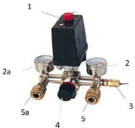
20.1 Switching machine ON/OFF
Switching the machine on: To switch on, pull out the ON/OFF switch (1)
Switching the machine off machine: To switch off, press in the ON/OFF switch (1) or with the
Motor-limit switch:
The motor is also controlled by a motor limit switch. When the maximum pressure in the vessel is reached, the motor stops. As a result of the air removal, the pressure drops and the electric motor starts again when the pressure falls below a minimum pressure. These two limit values are set at the factory and must not be changed!
20.2 Adjusting the output-pressure
With the pressure regulator (4) the output pressure can be adjusted at fitting (5a).
- To adjust the pressure, first set the lowest possible working pressure and then empty the line behind the pressure reducer. This is necessary so that the pressure gauge can react to the changed settings.
• To change the working pressure, first pull out the knob of the pressure reducer - Turning clockwise now increases the pressure.
• To lower it, the handle must be moved counter clockwise. - As soon as you can read the desired working pressure on the pressure gauge (2a), push the knob back in again to prevent the pressure from changing unintentionally!!
CAUTION

However, many technical devices require lower pressure. Therefore, always connect them to the regulated output (5a) and set them to a pressure below the maximum permissible working pressure. The vessel pressure is available at the outlet (5) and can be up to the maximum pressure of this machine.
20.3 Establishing the compressed air connection
Insert the nipple of the air pressure hose into the coupling. The sleeve automatically springs forward. To disconnect, pull back the sleeve of the coupling and remove the hose.
CAUTION

When disconnecting the hose coupling, hold the coupling piece of the hose firmly with your hand. This prevents injuries caused by a rebounding hose

natural_image
Close-up of a metallic cylindrical component with two circular red buttons and a small metallic knob (no text or symbols visible)MOTOR PROTECTION
The electric motor has a thermal overload protection. Should be a risk that the engine is overheated, this switches off automatically. In this case, the knob for the motor protection at the upper side of the protective cover jumps out.
First, let cool in such situations this! Then, the motor protection button can be pressed and your compressor works correctly.
21 MAINTENANCE
W ARNI NG

Handling the machine with the power supply or vessel pressure > ambient pressure up can lead to serious injuries or even death. Always disconnect the machine from the power supply and bring vessel pressure to ambient pressure before servicing or maintenance work and secure it against unintentional or unauthorised reconnection!
The machine requires low maintenance and only a few parts need to be serviced. Irrespective of this, faults or defects that could impair the safety of the user must be eliminated immediately!
• Before every operation, check the perfect condition of the safety devices.
- Check the connections for tightness at least once a week.
- Check regularly that the warning and safety labels of the machine are in perfect and legible condition.
21.1 maintenance plan
| Checks for maintenance of the machine | |
| Loose or lost screws | Before each use |
| Damage to machine parts | Before each use |
| Oil level | Before each use |
| Cleaning the machine | After each use |
| Emptying the autoclave condensate | After each use |
| Airfilter change | after 100h or if needed |
| Oil change | after the first 10h and then after 100h |
21.1.1 Changing the air filter
A clogged, dirty air filter considerably reduces the performance of your machine!
Change the air filters when you notice a reduction in performance or after the change interval has expired.
21.1.1 Emptying the autoclave condensate
To ensure the long-term durability of the pressure vessel, the condensation water must be drained off after each operation by opening the drain cock. The condensation water from the pressure vessel contains oil residues. Dispose of the condensation water in an environmentally friendly manner!
21.1.1 Oil change
NOT I CE


Oils are toxic and must not be released into the environment! If necessary, contact the local authorities for information on proper disposal.
To do this, empty the oil tank by opening the outlet screw, in the middle of which the sight glass is located, using a fork wrench. The oil must be collected in a container and then disposed of properly. Now close the oil outlet screw. Afterwards, oil can be filled in again and the inlet can be closed. Now let your machine run at idle for 2-3 minutes (see Initial start-up: Ensuring lubrication) and then check the oil level again..
22 CLEANING
NOT I CE

The use of solvents, aggressive chemicals or scouring agents can lead to damage to the paintwork and other material damage to the machine!
Clean the machine with a damp cloth and, if necessary, some commercial detergent or blow it out with compressed air at low pressure.
23 STORAGE
Before storing, clean the machine well, drain off condensation water. Pack the cleaned machine and store in a dry and clean place.
24 DISPOSAL

Observe the national waste disposal regulations. Do not dispose of the machine, machine components or operating materials in residual waste. If necessary, contact your local authorities for information on available disposal options.
If you purchase a new machine or equivalent from your dealer, the dealer is obliged in certain countries to dispose of your old machine properly.
25 TROUBLESHOOTING
W ARNI NG

Handling the machine with the power supply or vessel pressure > ambient pressure up can lead to serious injuries or even death. Always disconnect the machine from the power supply and bring vessel pressure to ambient pressure before servicing or maintenance work and secure it against unintentional or unauthorised reconnection!
If you find yourself unable to carry out necessary repairs properly and/or do not have the required skills to do so, always consult a specialist to solve the problem.
| Trouble | Possible cause | Solution |
| Pressure can no longer be stored | • Valve seals broken | • Replace the seals |
| Engine overheats | • low oil level• dirty air filter | • Refill oil• Clean or replace the air filter |
| Compressor runs but produces no pressure | • Clogged air filters• Defective seals• Defective valves in the cylinder head. | • Clean or replace the old air filter• Replace the seals• Replace the valves |
| Engine will not start | • No electricity | • Check the connection to an existing electrical grid.• Let the engine cool down and then drag the red pressure switch (on / off) |
| After reaching the escapes cut-off pressure Compressed air through the relief valve und Pressure switch to reach the starting pressure | • Leaking or defective check valve• Check valve is damaged | • Clean or replace check valve insert• Replace check valve |
| Compressor on frequently | • Very much condensate in the pressure boiler• Overload compressor | • Drain condensate |
26 SCHALTPLAN / WIRING DIAGRAM

27 ERSATZTEILE / SPARE PARTS
(EN) With original ZIPPER spare parts you use parts that are attuned to each other shorten the installation time and elongate your machines lifespan.
NO TI CE
The installation of other than original spare parts voids the warranty!
So you always have to use original spare parts
When you place a spare parts order please use the service formular you can find in the last chapter of this manual. Always take a note of the machine type, spare parts number and partname. We recommend to copy the spare parts diagram and mark the spare part you need.
Or use the electronic ordering opportunity via the spare parts catalogue or spare parts request form on our homepage
You find the order address in the preface of this operation manual.
(EN) For electronic spare-parts catalogue please refer to our homepage (spare-parts)
| NO | Designation | Qty | NO | Designation | Qty |
| 1 | BOLTM6X55 | 4 | 38 | STATOR | 1 |
| 2 | CYLINDER HEAD | 1 | 39 | ROTOR | 1 |
| 3 | CYLINDER HEAD GASKET | 2 | 40 | BEARING 6202 | 1 |
| 4 | VALVE PLATE | 2 | 41 | WASHER D35 | 1 |
| 5 | VALVE PLATE GASKET | 2 | 42 | SWITCH | 1 |
| 6 | VALVE | 2 | 43 | SWITCH | 1 |
| 7 | PIN | 4 | 44 | END COVER | 1 |
| 8 | CYLINDER | 2 | 45 | COVER | 1 |
| 9 | CYLINDER GASKET | 2 | 46 | BOLT M5X30 | 6 |
| 10 | PISTON RING | 4 | 47 | FAN | 1 |
| 11 | PISTON RING | 2 | 48 | CIRCLIP | 1 |
| 12 | PISTON | 2 | 49 | FAN COVER | 1 |
| 13 | PISTON PIN | 2 | 50 | BOLT ST4.8X16 | 5 |
| 14 | CIRCLIP | 4 | 51 | DELIVERY PIPE | 1 |
| 15 | CONNECTING ROD | 2 | 52 | NUT M8 | 4 |
| 16 | CRANK CASE GASKET | 1 | 53 | DELIVERY PIPE | 1 |
| 17 | CRANK CASE COVER | 1 | 54 | BOLT M8X25 | 4 |
| 18 | BOLT M5X16 | 6 | 55 | ONE-WAY VALVE | 1 |
| 19 | SIGHT GLASS GASKET | 1 | 56 | AXLE | 2 |
| 20 | SIGHT GLASS | 1 | 57 | SPACER | 2 |
| 21 | BOLT M6X10 | 1 | 58 | WHEEL | 2 |
| 22 | O CIRCLIP Φ5.6XΦ1.8 | 1 | 59 | NUT | 2 |
| 23 | HEX BOLT M8X22(LEFT) | 1 | 60 | NUT M10 | 2 |
| 24 | CRANK SHAFT | 1 | 61 | WASHER | 4 |
| 25 | CRANK CASE | 1 | 62 | DRAIN VALVE | 1 |
| 26 | BOLT M6X40 | 8 | 63 | BOLT M8X25 | 2 |
| 27 | SEALING RING | 1 | 64 | RUBBER FOOT | 2 |
| 28 | BEARING 6204 | 1 | 65 | NUT M8 | 2 |
| 29 | CAPACITOR | 1 | 66 | NUT | 1 |
| 30 | NUT M8 | 2 | 67 | JOINT | 1 |
| 31 | CAPACITOR | 1 | 68 | SAFETY VALVE | 1 |
| 32 | END COVER | 1 | 69 | REGULATOR | 2 |
| 33 | BOLT M8X25 | 4 | 70 | PRESSURE GAUGE | 2 |
| 34 | OUTLET ELBOW | 1 | 71 | PRESSURE SWITCH | 1 |
| 35 | PIPE | 1 | 72 | POWER CABLE | 1 |
| 36 | OUTLET ELBOW | 1 | 73 | RUBBER HANDLE | 1 |
| 37 | AIR FILTER | 2 | 74 |
Company ZIPPER Maschinen GmbH grants for mechanical and electrical components a warranty period of 2 years for amateur use; and warranty period of 1 year for professional use, starting with the purchase of the final consumer. In case of defects during this period, which are not excluded by paragraph 3, ZIPPER will repair or replace the machine at its own discretion.
2.) Report:
In order to check the legitimacy of warranty claims, the final consumer must contact his dealer. The dealer has to report in written form the occurred defect to ZIPPER. If the warranty claim is legitimate, ZIPPER will pick up the defective machine from the dealer. Returned shippings by dealers which have not been coordinated with ZIPPER, will not be accepted and refused.
3.) Regulations:
a) Warranty claims will only be accepted, when a copy of the original invoice or cash voucher from the trading partner of ZIPPER is enclosed to the machine. The warranty claim expires if the accessories belonging to the machine are missing.
b) The warranty does not include free checking, maintenance, inspection or service works on the machine. Defects due to incorrect usage of the final consumer or his dealer will not be accepted as warranty claims either. Some examples: usage of wrong fuel, frost damages in water tanks, leaving fuel in the tank during the winter, etc.
c) Defects on wear parts are excluded, e.g. carbon brushes, collection bags, knives, cylinders, cutting blades, clutches, sealings, wheels, saw blades, splitting crosses, riving knives, riving knife extensions, hydraulic oils, oil/air/fuel filters, chains, spark plugs, sliding blocks, etc.
d) Also excluded are damages on the machine caused by incorrect or inappropriate usage, if it was used for a purpose which the machine is not supposed to, ignoring the user manual, force majeure, repairs or technical manipulations by not authorized workshops or by the customer himself, usage of non-original ZIPPER spare parts or accessories.
e) After inspection by our qualified personnel, resulted costs (like freight charges) and expenses for not legitimated warranty claims will be charged to the final customer or dealer.
f) In case of defective machines outside the warranty period, we will only repair after advance payment or dealer's invoice according to the cost estimate (incl. freight costs) of ZIPPER.
g) Warranty claims can only be granted for customers of an authorized ZIPPER dealer who directly purchased the machine from ZIPPER. These claims are not transferable in case of multiple sales of the machine.
4.) Claims for compensation and other liabilities:
The liability of company ZIPPER is limited to the value of goods in all cases. Claims for compensation because of poor performance, lacks, damages or loss of earnings due to defects during the warranty period will not be accepted. ZIPPER insists on its right to subsequent improvement of the machine.
We monitor the quality of our delivered products in the frame of a Quality Management policy.
Your opinion is essential for further product development and product choice. Please let us know about your:
- Impressions and suggestions for improvement.
- experiences that may be useful for other users and for product design
- Experiences with malfunctions that occur in specific operation modes
We would like to ask you to note down your experiences and observations and send them to us via FAX, E-Mail or by post:
Erworben von / purchased from:
E-Mail/ e-mail:
Please describe amongst others in the problem: What has cause the problem/defect, what was the last activity before you noticed the problem/defect? For electrical problems: Have you had checked you electric supply and the machine already by a certified electrician?
3. Bitte beachten
/ Additional information
INCOMPLETELY FILLED SERVICE FORMS CANNOT BE PROCESSED! FOR GUARANTEE CLAIMS PLEASE ADD A COPY OF YOUR ORIGINAL SALES / DELIVERY RECEIPT OTHERWISE IT CANNOT BE ACCEPTED. FOR SPARE PART ORDERS PLEASE ADD TO THIS SERVICE FORM A COPY OF THE RESPECTIVE EXPLODED DRAWING WITH THE REQUIRED SPARE PARTS BEING MARKED CLEARLY AND UNMISTAKABLE. THIS HELPS US TO IDENTIFY THE REQUIRED SPARE PARTS FASTLY AND ACCEL- LERATES THE HANDLING OF YOUR INQUIRY.


- TRANSPORT 19
- ASSEMBLY 20
- START UP CHECKLIST 21
- OPERATION 22
- MAINTENANCE 23
- TECHNIK / TECHNIC
- Montage Luftfilter
- MOTORSCHUTZ
- Please read and obey the security instructions!
- Copyright
- Customer Service Address
- Intended Use of the Machine
- Technical Restrictions
- Prohibited Use / Forseeable Misuse
- User Requirements
- Safety Devices
- General Safety Instructions
- Electrical Safety
- Special Safety Instructions for that machine
- Hazard Warnings
- DANGER
- WARNING
- CAUTION
- NOTICE
- TRANSPORT
- ASSEMBLY
- Checking scope of delivery
- Setting up the device
- Assembly
- Assembly the wheels
- assembly rubber feet
- assembly drain screw
- Assembly air filter
- Assembly oil vent valve
- START UP CHECKLIST
- Oil-level check / refilling oil
- NOT I CE
- Additional notes
- Initial start up
- OPERATION
- Switching machine ON/OFF
- Motor-limit switch:
- Adjusting the output-pressure
- Establishing the compressed air connection
- MOTOR PROTECTION
- MAINTENANCE
- W ARNI NG
- maintenance plan
- Changing the air filter
- Emptying the autoclave condensate
- Oil change
- CLEANING
- STORAGE
- DISPOSAL
- TROUBLESHOOTING
- ERSATZTEILE / SPARE PARTS
- NO TI CE
- The installation of other than original spare parts voids the warranty!
- 2.) Report:
- 3.) Regulations:
- 4.) Claims for compensation and other liabilities:
- Bitte beachten
- / Additional information
Brand : Zipper
Model : ZI-COM100-2V5
Category : Compressor