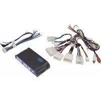
RP4.2-TY11 - Car audio interface PAC - Free user manual and instructions
Find the device manual for free RP4.2-TY11 PAC in PDF.


| Product Type | Network Router |
| Model | RP4.2-TY11 |
| Brand | PAC |
| Dimensions (W x D x H) | 200 x 150 x 30 mm |
| Weight | 0.5 kg |
| Power Input | 12V DC, 1A |
| Wireless Standard | 802.11n |
| Ethernet Ports | 4 x LAN, 1 x WAN |
| LED Indicators | Power, Internet, LAN, WLAN |
| Antenna Type | Internal |
| Operating Temperature | 0°C to 40°C |
| Functions | Wireless access point, DHCP server, firewall, NAT |
| Maintenance | Clean with soft dry cloth; avoid liquids |
| Safety Precautions | Do not expose to water or high humidity. Use only supplied power adapter. |
| Spare Parts Availability | Contact PAC support for replacement parts |
Frequently Asked Questions - RP4.2-TY11 PAC
User questions about RP4.2-TY11 PAC
0 question about this device. Answer the ones you know or ask your own.
Ask a new question about this device
Download the instructions for your Car audio interface in PDF format for free! Find your manual RP4.2-TY11 - PAC and take your electronic device back in hand. On this page are published all the documents necessary for the use of your device. RP4.2-TY11 by PAC.
USER MANUAL RP4.2-TY11 PAC
Introduction & Features
The RP4.2-TY11 interface allows the replacement of a factory radio in select Toyota/Lexus/Scion vehicles and will retain factory features such as steering wheel controls (SWC) and the factory audio amplifier. This interface also allows you to program two radio functions to each SWC button by using short press long press dual command functionality, and also provides outputs such as: vehicle speed signal (VSS), illumination, reverse trigger and parking brake.
Important Notes
- These instructions only apply to R1.1.1.35 or earlier revisions. The revision info can be found on a small white sticker on the interface and packaging.
- Connection of the White / Red and White / Black wires is not always necessary. Use of these wires will be dependent on whether or not the aftermarket radio requires specific connections, and whether the vehicle provides these outputs at the radio. See the "Installation Steps" section starting on page 3 for additional information.
- Adjustment of the vehicle settings through the original radio's vehicle settings menu will be disabled after installation of the new radio. It is advised to make sure all settings are as you desire prior to removal of the original radio.
- The RP4.2-TY11 does not retain Rear Seat Entertainment.
- After installation, if you do not initially hear any audio, you may need to cycle the ignition again to initialize the factory amplifier.
- Speaker fading on factory amplified systems is only supported with the "amplified output" connection of the RP4.2-TY11.
- When using real time fade, if the fader setting is biased more to the front or rear, as the radio turns on the sound may begin at the default setting and then quickly transition to your custom setting.
- Aftermarket radio features such as High Pass Filters (crossovers), DSP or "Network Mode" will interfere with proper fader function. In order for the RP4.2-TY11's fader function to work, the audio from the aftermarket radio's output must match so it can compare the front and rear audio levels and determine the proper fader setting for the factory amplifier.
- The USB-TY1 or USB-TY2 must be purchased in order to retain the factory USB port. Please refer to www.pac-audio.com to see which harness you will need.
- The CAM-TY11 or CAM-TY12 must be purchased in order to retain the factory reverse camera. Please refer to www.pac-audio.com to see which harness you will need. If the required harness is not available, it is possible to hardwire the reverse camera using the information provided in Appendix A on Page 9.
Module Layout
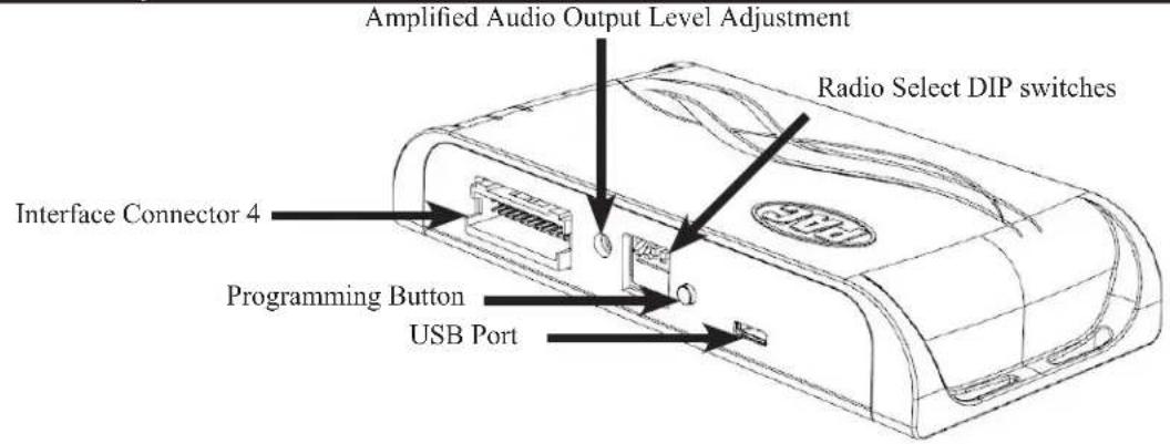
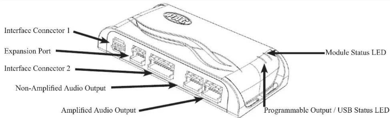
Interface Connectors
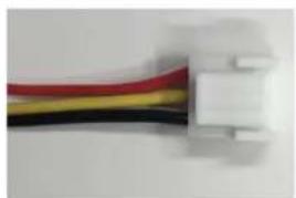
natural_image
Close-up of a white plastic connector with red, yellow, and black wires attached (no text or symbols visible)Interface Connector 1

natural_image
Close-up of a white cable with red and black wires, no visible text or symbolsInterface Connector 2
natural_image
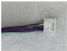
Close-up of a multicolored cable with a small label on the left (no visible text or symbols)Interface Connector 3

Interface Connector 4
Plug Interface Connectors 1, 2 and 4 into the appropriate port on the RP4.2-TY11 interface (according to diagram on page 1 or the label on the bottom of the RP4.2-TY11 interface). The Connector 3 connection will be dependent upon whether or not the vehicle has a factory amplified system. Connect to the appropriate port on the RP4.2-TY11. If you are unsure as to what your application is, connect to the Amplified Audio Output port and change to the Non-Amplified Audio Output port if you experience low audio.
Vehicle Connectors

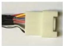
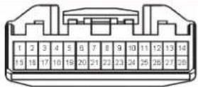

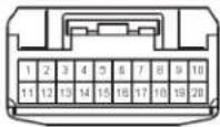
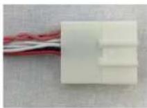


Vehicle Connector 1
Vehicle Connector 2
Vehicle Connector 3
Vehicle Connector 4
Vehicle Connector 5
Depending on the application, the RP4.2-TYII will need 2 or 3 of the 5 vehicle connectors. The additional connectors will be left unused on the harness. Any additional radio harnesses in the vehicle that do not plug into one of the vehicle connectors shown above, will not be used. Below you will find the typical combinations needed for most vehicles.
Combination 1
Typical 2004 to 2013 NON-AMPLIFIED

Vehicle Connector 3 Vehicle Connector 4


Vehicle Connector 5
Combination 2
Typical 2004 to 2013 AMPLIFIED
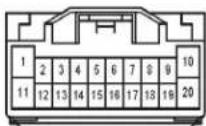
Vehicle Connector 1 Vehicle Connector 3

Combination 3
Typical 2014 to 2017 AMPLIFIED AND NON-AMPLIFIED
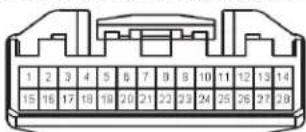
Vehicle Connector 2

Vehicle Connector 4

Vehicle Connector 5
Installation Steps
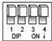
Set DIP switches that correspond with your radio to the ON position. Set all other DIP switches to the OFF position.

| Alpine JV | Kenwood | Clarion / Nakamichi | Pioneer / Other* | Sony Fusion | ||
| 1 2 1 & | 2 3 1, 2, & 3 4 | 1 & 4 |
* Other - Advent, BOYO, Dual, Jensen, Lightning Audio, Rockford Fosgate, Visteon
- Set the Radio Select DIP switches according to the radio you are installing.
- Wire the aftermarket radio harness per the tables to the right and the information below. If the aftermarket radio does not require connections for Vehicle Speed Sense, Parking Brake, or Reverse Signal, proceed to step "3".
a. If the vehicle does not use the 28 pin connector (Vehicle Connector 2), proceed to step "III" below. There are three different methods for obtaining the analog navigation outputs from the interface:
I. Vehicles that have the analog signals at the radio: Plug the 28 pin connector (Vehicle Connector 2) from the RP4.2-TY11 into the vehicle harness. Find the Pink (pin 17), Light Green (pin 15) and Purple / White (pin 2) wires in the RP4.2-TY11 harness and check for wires populating these positions on the factory side of the connector. If the wires are present, you can use the analog navigation outputs coming from the Vehicle Connector in the PAC harness.
II. Vehicles that have CAN data at the radio: Plug the 28 pin connector (Vehicle Connector 2) from the RP4.2-TY11 into the vehicle harness. Find the White / Red (pin 9) and White / Black (pin 10) wires in the RP4.2-TY11 harness and check for wires populating these positions on the factory side of the connector. If the wires are present, you can use the "nav wires" coming from Vehicle Connector 2 in the PAC harness.
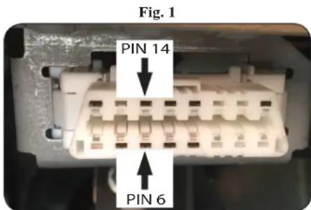
III. Vehicles that do not have the CAN data or the analog wires at the radio: Connect the long White / Red HS-CAN+ wire to pin 6 and the long White / Black HS-CAN- wire to pin 14 in the OBDII connector (Fig.1). This will allow for use of the "nav wires" coming from Interface Connector 4 in the PAC harness.
-
Wire the Yellow, Red, Black and Blue / White wires from the harness labeled "Connect to Aftermarket Radio" to the wires on the aftermarket radio harness. The Red / White wire is optional (see page 7 for further details).
-
Wire the speaker wires from Interface Connector 4 to the speaker wires on the aftermarket radio harness. The Blue / White and Brown wires from Interface Connector 4 will not be needed. Insulate the unused wires and ignore the remaining Brown Loop (not needed).
-
Depending on the aftermarket radio, either the Blue / Yellow wire or the 3.5 mm Jack (not both) SWC Outputs will be used.
Aftermarket Radio Wiring Table
| Purple Rear | R + input |
| Purple / Black Rear | R - input |
| Green Rear L + input | |
| Green / Black | Rear L - input |
| Gray | Front R + input |
| Gray / Black | Front R - input |
| White | Front L + input |
| White / Black Front L - input | |
| Blue / Yellow | SWC Output |
| 3.5 mm Jack | SWC Output |
| Pink | Vehicle SpeedSense Output |
| Light Green | Parking BrakeOutput |
| Violet / White | Reverse SignalOutput |
| Orange / White | Illumination Output |
Wires Labeled "Connect To Aftermarket Radio"
| Yellow 12v+ | |
| Red | Accessory Output (10 amp) |
| Black | Ground |
| Blue / White | Amp Turn On |
| Pink | Vehicle Speed Sense Output |
| Light Green | Parking Brake Output |
| Red / White | Programmable 12v+ Output (1 amp) |
| Violet / White | Reverse Signal Output |
CAN Input Wires
| White / Red | HS CAN + Input |
| White / Black | HS CAN - Input |
Installation Steps (cont.)
- Once all connections have been made, plug the interface into the vehicle.
- Turn the ignition on and set the gain on the side of the interface to the desired level. See "Testing & Verification" section on page 6 for further details on how to set the gain. If the radio does not turn on and the LED on the interface is solid orange, check the DIP switches on the side of the interface to make sure they are not all in the on position.
- If you wish to reassign functions to the SWC, or utilize short press long press dual command functionality, follow the programming instructions below.
Steering Wheel Controls
Default Steering Wheel Control Programming
IMPORTANT! The interface comes pre-programmed for all of the vehicles factory SWC functions and does not require programming unless you wish to re-assign the SWC functions, utilize short press long press dual command functionality, or assign the programmable 12v output to a SWC button. The SWC can always be restored to default settings by pressing and releasing the program button on the side of the interface once and waiting 7 seconds for the LED to flash 3 times.
Default SWC Button Assignments
| Alpine | JVC | Kenwood | Clarion | Pioneer | Sony | Fusion | |
| Volume + | Volume + | Volume + | Volume + | Volume + | Volume + | Volume + | Volume + |
| Volume - | Volume - | Volume - | Volume - | Volume - | Volume - | Volume - | Volume - |
| Mode | Source | Source | Source | Source | Source | Source | Source |
| Back | Band | Att | Play | Band | Band | Band | N / P |
| Voice | VR | Mute | Mute | Mute | VR | Mute | Mute |
| Answer | Receive | Receive | Off Hook | Send | Answer | Answer | Power |
| End | End | Reject | On Hook | End | End | Reject / Source | N / P |
| Enter | Power | Power | Preset Up | N / P | Mute | N/P | Power |
| Arrow Up | Track Up | Track Up | Track Up | Track Up | Track Up | Track Up | Track Up |
| Arrow Down | Track Down | Track Down | Track Down | Track Down | Track Down | Track Down | Track Down |
| Arrow Left | Preset Down | Disc Down | Disc Down | N / P | Preset Down | Preset Down | N / P |
| Arrow Right | Preset Up | Disc Up | Disc Up | N / P | Preset Up | Preset Up | N / P |
Optional Steering Wheel Control Programming
If you wish to re-assign the SWC functions, utilize short press long press dual command functionality, or assign the programmable 12v output to a SWC button, the interface must be programmed in the specific order shown in the chart on page 5. If you come across a function in the chart that your steering wheel does not have, or you do not want to program, press and release the programming button on the side of the interface to skip that function. The LED will flash off and on confirming that you have successfully skipped that function and are ready to proceed to the next one.
Short Press Long Press Dual Command Functionality
This feature allows you to assign two aftermarket radio functions to each of the vehicles SWC buttons. It can be used with as many of the buttons as the user likes or none at all. When this functionality is implemented, quickly pressing and releasing a SWC button will initiate the short press command while pressing and holding a SWC button for longer than two seconds will initiate the long press command. Please note that no long press commands are programmed by default. If you wish to assign dual command functionality to the SWC please follow the programming steps below.
Programmable 12v Output
The Red / White wire on the interface can be programmed via the RadioPRO app to do a pulsed, or latched 12v output, which can then be assigned to any of the vehicle's factory SWC buttons. When assigned, the factory SWC button will activate the pulsed or latched output to control external accessories. Please refer to page 7 for more details on how to use the app to set this feature.
Steering Wheel Controls (cont.)
Optional SWC Programming Procedure
- Turn the key to the ignition position.
- Press and release programming button on the side of the interface. The Status LED will turn green.
- Within 7 seconds, press the button that is to be learned on the steering wheel. The LED will turn red when the button is pressed.
At this point you have two options:
A. For short press functionality: Release the button within 1.5 seconds. The LED will turn back on.
B. For long press functionality: Hold the button until the LED starts blinking. Release the button and the LED will go back to solid.
- If you need to program more buttons, repeat step 3 for each additional audio function on the steering wheel.
- If you come across a function in the chart that your steering wheel does not have, or you do not want to program, press and release the program button on the side of the interface to skip that function.
- Once programming is completed, wait seven seconds. The LED will flash three times indicating end of programming.
- Test the interface for proper functionality. Whenever a SWC is pressed the LED on the interface should blink. If any function does not work, repeat the programming steps.
Optional Programming Order
| Alpine JVC Kenwood Clarion Otter * Pioneer Sony Fusion | ||||||||
| 1 Volume - | Volume + Volume + | Volume + Volume + | Volume + Volume + | Volume + | ||||
| 2 | Volume - | Volume - | Volume - | Volume - | Volume - | Volume - | Volume - | Volume - |
| 3 | Mute | Mute | Mute | Mute | Mute | Mute | Mute | Mute |
| 4 | Preset + | Source | Source | Source | Preset + | Preset + | Preset + | Source |
| 5 | Preset - | Track + | Play | Search + | Preset - | Preset - | Preset - | Track + |
| 6 | Source | Track - | Track + | Search - | Source | Source | Source / End Call | Track - |
| 7 | Track + | Band / Disc + | Track - | Band | Track + | Track + | Track + | Audio |
| 8 | Track - | Preset / Disc - | Disc / FM + | Send / End | Track - | Track - | Track - | Power |
| 9 | Power | Select | Disc / AM - | Send | Band | Band | Band | |
| 10 | Enter / Play | Attenuation | Answer | End | Answer ** | Phone Menu | Power / End Call | |
| 11 | Band / Program | Phone Receive | Voice Dial | VR | End ** | Answer Call | Voice Dial / Answer / End Call | |
| 12 | Receive | Phone Reject | On Hook | PTT ** | End Call | VR (Android Auto & Car Play) Answer / End Call*** | ||
| 13 End | Voice Dial Off Hook | VR | ||||||
| 14 | VR | Power | Mute | |||||
| 15 | Preset + | |||||||
| * Advent, Boyo, Dual, Lightning Audio, Jensen, Rockford Fosgate & Visteon ** Jensen & Advent ONLY *** XAV-AX100 Only | ||||||||
Steering Wheel Controls (cont.)
SWC Re-Calibration Procedure
- Turn the key to the ignition position.
- Press and hold the programming button until the LED begins blinking amber. When the LED begins blinking, release the programming button. The LED will light solid amber.
- Within 7 seconds, press and hold the button that is to be learned on the steering wheel. The LED will turn off when the button is pressed and begin blinking when the value has been learned. Once the LED begins blinking, release the button. Please Note: the buttons must be calibrated in the order shown in the chart. If you press the wrong button the LED will not respond at all.
- If you need to program more buttons, repeat step 3 for each additional audio function on the steering wheel.
- If you come across a function in the chart that your steering wheel does not have, press and release the program button on the side of the interface to skip that function.
-
Once programming is completed, wait seven seconds. The LED will flash indicating end of programming.
-
Test the interface for proper functionality. Whenever a SWC is pressed the LED on the interface should blink. If any function does not work, repeat the programming steps.
| Re-Calibration Programming Order |
| Volume Up |
| Volume Down |
| Seek Up |
| Seek Down |
| Mode |
| Voice |
| Phone Answer |
| Phone Hang Up |
| Enter |
| Back |
| Arrow Right |
| Arrow Left |
After you have re-calibrated the SWC buttons, the default SWC button assignments will be the same as what is listed in the chart on page 4. If you wish to re-assign button functions you must also go through the programming process on page 5.
Testing & Verification
- Turn the ignition on. The LED on the interface will turn on and the +12v accessory wire will turn on.
- Turn on the radio and check volume, balance and fade. If you do not hear any audio you may need to cycle the ignition to initialize the factory amplifier.
- If the overall volume is too low, use the gain adjustment on the side of the RP4.2 interface to set it to the desired level. The best way to do this is to turn the volume on the radio to 3/4 volume, then turn the gain on the RP4.2 until some distortion is heard, then back it down a little.
- If you have a JBL system and there is no audio, please make sure the Blue / White remote wire in the radio connector is hooked up properly. If there is still no audio, reset the interface according to the procedure in the next section.
- If fading is acting inconsistent, please ensure that all speakers are connected to the proper polarity.
- Verify that all SWC are functioning properly. If any of the SWC are not functioning properly you may need to reset the interface or follow the re-calibration procedure above.
- Verify that the programmable 12v+ output is functioning as intended.
- The LED and radio will turn off when the ignition is turned off.
Restoring Factory Settings
You can restore the interface to factory default settings by pressing and holding the programming button on the side of the module until the status LED starts blinking red. Once the LED starts blinking red, release the button. You must release the button while the LED is blinking red in order to perform the reset. Please note, the LED will go through two stages before it starts blinking red. First it will blink green, then amber, then red.
This reset will restore the following settings to their factory defaults:
- SWC Mapping
- Programmable 12v+ Output (Latched)
- Parking Brake Output Settings
• Factory Amplifier Settings
• Real Time Fade will be reset to on
RadioPRO App
Use of the RadioPRO App allows you to do the following:
- Configure User Interface Options such as:
-
Programmable 12v Output behavior
• Aftermarket radio Parking Brake Sequencing
• Factory amplifier settings (Bass, Mid, Treble, Gain, Fader and Balance)
• Real Time Fading -
Update Product Firmware
- Read Firmware/Hardware Versions
- Access Product User Manuals
PLEASE NOTE:
The interface must be connected to the vehicle when using the following features of the Radio PRO App:
• Programmable 12v Output Behavior
• Factory Amplifier Settings
The interface does not need to be connected to the vehicle when using the following features of the Radio PRO App:
- Firmware Updates
- Reading firmware/hardware versions
Programmable 12v Output Wire
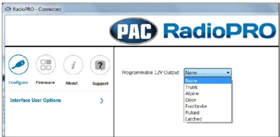
The Red / White wire can be programmed to do a pulsed or latched trigger that is controlled by a user assigned steering wheel control button, or it can be set to provide an output when triggered by the vehicles foot brake, door or trunk. Select User Interface Options then set the behavior of the Red / White wire using the drop down menu. PLEASE NOTE: Available triggers depend on what info is available on the vehicle's data bus. Restoring factory settings on the module will default this wire's output back to a latched SWC trigger.
Trunk - This selection will provide a 12v+ output on the Red / White wire whenever the ignition is on and the trunk is opened.
Alpine - If you select the "Alpine" setting on the drop down menu, the Red / White wire will then work in conjunction with the parking brake output to produce the necessary sequencing for settings menu access. This sequencing is based on the actual parking brake, meaning to produce this sequence you have to engage the parking brake in the vehicle. If you would like to manually do the necessary foot brake/parking brake sequencing for Alpine, select the "Foot Brake" setting (if available) and the Red / White wire will output a 12v+ signal whenever the signal is available and the foot brake is pressed.
Door - This selection will provide a 12v+ output on the Red / White wire whenever the signal is available and any door on the vehicle is opened.
Footbrake - This selection will provide a 12v+ output on the Red / White wire whenever the signal is available and the foot brake is pressed.
Latched - This selection will provide a latched 12v+ output that can be tied to any of the vehicles SWC. This means that when you press the assigned SWC, the Red / White wire will turn on and remain on until the assigned SWC is pressed again or the ignition is turned off.
Pulsed - This selection will provide a user programmable timed 12v+ output that can be tied to any of the vehicles SWC. This means that when you press the assigned SWC, the Red / White wire will pulse for the pre-programmed user time. The range for pulse time is 100 milliseconds - 25.5 seconds (.1-25.5).
RadioPRO App (cont.)

Pioneer Parking Brake - Turning this feature on will make the parking brake output produce the necessary sequencing for settings menu access. This sequencing is based on the actual parking brake, meaning to produce this sequence you have to engage the parking brake in the vehicle. If you would like to manually do the necessary parking brake sequencing for Pioneer, simply leave this feature off. Restoring factory settings on the module will default this setting back to off.

Infotainment/Factory Amplifier Settings
The RadioPRO app will also allow you to adjust the settings of the factory amplifier. You can adjust Amp Gain, Fader, Balance, Bass, Mid and Treble and real time fade. When real time fade is enabled in amplified systems, it will allow fading to be controlled directly from the aftermarket radio. Restoring factory settings on the module will default all values back to middle.

RadioPRO App (cont.)
Firmware Updates
The RadioPRO app will also allow you to update the interface with new firmware as it becomes available. Please visit www.pac-audio.com or contact our tech support department to see if there is a firmware update for your interface.
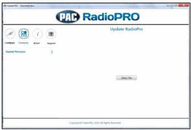
In order to update the interface all DIP switches must be set to the down position. Connect the interface to your PC and select "Update Firmware". Now select "Select File". Finally, browse to the place where you saved the file and select it. This will begin the updating process. Once finished, disconnect the interface from the PC and set the DIP switches back according to the radio you have installed.

Appendix A
Reverse Camera Retention
If you do not have the CAM-TY11 or CAM-TY12 harness available, follow the schematics below to retain the factory reverse camera. Older vehicles (pre 2014) will be equipped with the 16-pin harness (Fig. 1) and newer vehicles (2014+) will be equipped with the 24-pin harness (Fig.2). Some years may overlap.
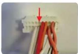
You can obtain the necessary 6v+ for the factory camera from pin 12 in the RP4.2 Interface Connector 2 (Fig.3), or by using the PAC VOLT-39 (sold separately).
Fig. 1
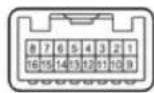
| Function Pin Wire Color | |
| Camera Power 6V + 7 Black | |
| Video + 8 | Red |
| Camera Ground 15 Shield | |
| Video - 16 | White |
Fig. 2
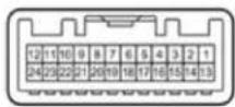
| Function Pin Wire Color | |
| Camera Power 6V+ 1 | Red |
| Video + 12 White | |
| Camera Ground 23 Shield | |
| Video - 24 Black |
Fig. 3
natural_image
Close-up of a white electrical terminal with red wires and a red arrow pointing to a component (no visible text or symbols)Connectors are viewed from wire side


- Introduction & Features
- Important Notes
- Combination 1
- Combination 2
- Combination 3
- Installation Steps
- Installation Steps (cont.)
- Steering Wheel Controls
- Default Steering Wheel Control Programming
- Optional Steering Wheel Control Programming
- Short Press Long Press Dual Command Functionality
- Programmable 12v Output
- Steering Wheel Controls (cont.)
- Optional SWC Programming Procedure
- At this point you have two options:
- SWC Re-Calibration Procedure
- Testing & Verification
- Restoring Factory Settings
- RadioPRO App
- Use of the RadioPRO App allows you to do the following:
- PLEASE NOTE:
- Programmable 12v Output Wire
- RadioPRO App (cont.)
- Infotainment/Factory Amplifier Settings
- Firmware Updates
- Appendix A
- Reverse Camera Retention
Brand : PAC
Model : RP4.2-TY11
Category : Car audio interface