
11405 - Système de désinfection UV ASTRALPOOL - Free user manual and instructions
Find the device manual for free 11405 ASTRALPOOL in PDF.


| Product Type | UV Disinfection System |
| Model | 11405 (110W) |
| Bulb Wattage | 110W |
| Energy Consumption | 89W |
| Power Supply | 220-240V, 50Hz |
| Number of UV Lamps | 2 |
| Maximum Flow Rate | 25,000 L/h |
| Maximum System Volume | 75,000 L |
| Maximum Operating Pressure | 2.5 Bar |
| Ingress Protection | IPX5 |
| Electrical Class | Class 1 |
| Recommended RCD Rating | 30mA |
| UV Bulb Lifespan | 9000 hours (approx. 1 year) |
| Quartz Sleeve Material | Quartz |
| Installation Requirements | Licensed electrician per AS/NZS 3000 |
| Maintenance | Annual bulb replacement; quartz sleeve cleaning with vinegar |
| Warranty | Limited factory warranty; register online |
| Included Accessories | Quartz sleeve, O-rings, locking nuts, end caps, mounting brackets |
| Saltwater Compatibility | Yes, but use alternative mounting for bracket |
| Ozone Compatibility | Yes, with rigid pipe (O-rings not ozone-resistant) |
| Continuous Operation | 24/7; frost-protected if outdoors in winter |
Frequently Asked Questions - 11405 ASTRALPOOL
User questions about 11405 ASTRALPOOL
0 question about this device. Answer the ones you know or ask your own.
Ask a new question about this device
Download the instructions for your Système de désinfection UV in PDF format for free! Find your manual 11405 - ASTRALPOOL and take your electronic device back in hand. On this page are published all the documents necessary for the use of your device. 11405 by ASTRALPOOL.
USER MANUAL 11405 ASTRALPOOL
natural_image
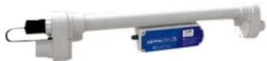
Exterior view of a white cylindrical electronic device with black connectors and a blue internal component (no visible text or symbols)11405 110W
natural_image
Exterior view of a white cylindrical device with black connectors and a blue rectangular component (no visible text or symbols)11404 55W
ASTRALPOOL UV DISINFECTION SYSTEM
WARNING
FOR YOUR SAFETY - This product must be installed and serviced by a licensed electrician in accordance with the latest, enforced version of AS/NZS 3000 and any other applicable local installation codes. Before installing this product, read and follow all warning notices and instructions that accompany this product. Failure to follow warning notices and instructions may result in property damage, personal injury, or death. Improper installation and/or operation will void the warranty.
Improper installation and/or operation can create unwanted electrical hazard which can cause serious injury, property damage, or death.
EQUIPMENT INFORMATION RECORD
| DATE OF INSTALLATION | |
| INSTALLER INFORMATION | |
| INITIAL PRESSURE GAUGE READING(WITH CLEAN FILTER) | |
| PUMP MODEL | |
| HORSEPOWER | |
| FILTER MODEL | |
| CONTROL PANEL MODEL | |
| SERIAL NUMBER |
TABLE OF CONTENTS
Section 1. Important Safety Instructions ...... 4
Section 2. Product Information ....5
2.1 Energy Consumption....5
2.2 Disposal Of Your Old Product ....5
Section 3. Introduction......5
3.1 The AstralPool UV Disinfection System....5
3.2 Unboxing the UV....5
Section 4. Components....6
4.1 11404 - 55 Watt Components....6
4.2 11405 - 110 Watt Components....6
Section 5. Flow Rates....7
Section 6. Installation....7
6.1 Install the Quartz Sleeve....7
6.2 Testing the Quartz, O-Rings and Locking Nuts .....8
6.3 Install the UV Bulb....8
6.4 Connect to the Electricity Suppy....9
Section 7. Maintenance....9
7.1 UV Bulb Replacement....9
7.2 Replace / Clean Quartz Supply....9
Section 8. Troubleshooting....10
Section 9. Frequently Asked Questions......10
Section 10. Warranty....11
Section 1. Important Safety Instructions
READ AND FOLLOW ALL INSTRUCTIONS
All electrical work must be performed by a licensed electrician and conform to all national, state, and local codes. When installing and using this electrical equipment, basic safety precautions should always be followed, including the following:
DANGER
This appliance is not intended for use by persons (including children) with reduced physical, sensory or mental capabilities, or lack of experience and knowledge, unless they have been given supervision or instruction concerning use of the appliance by a person responsible for their safety.
WARNING
To reduce the risk of severe injury or death, do not operate the UV-C emitter when it is removed from the appliance enclosure. Unintended use of the appliance or damage to the housing may result in the escape of dangerous UV-C radiation. UV-C radiation may, even in little doses, cause harm to the eyes and skin. Never look directly at an illuminated UV bulb.
CAUTION
Power must be supplied through a Residual Current Device (RCD) with a residual operating current not exceeding 30mA.
SAVE THESE INSTRUCTIONS
Section 2. Product Information
2.1 Energy Consumption
| 11404UV 55 Watt Clarifier | 11405UV 110 Watt Clarifier | |
| Energy Consumption: | 45W 89W | |
| Power: | 220-240V, 50Hz. | |
| SPEC | Class 1, IPX5 | |
| Operating Pressure: | Max 2.5 Bar | |
Table 1. The energy consumption of the unit is lower than the wattage of the bulb due to the high efficiency of the ballast.
2.2 Disposal Of Your Old Product
Please act according to your local rules and do not dispose of your old products with your normal household waste. The correct disposal of your old product will help prevent potential negative consequences for the environment and human health.
Section 3. Introduction
3.1 The AstralPool UV Disinfection System
The AstralPool UV Disinfection System has been manufactured using the latest technology and design techniques. The AstralPool UV Disinfection System will work alongside many different filtration systems designed in combination with a residual sanitiser to disinfect pool water.
Please read this manual carefully before attempting to install your AstralPool UV Disinfection System.
3.2 Unboxing the UV
The UV bulb and quartz sleeve are packed separately. Refer to pages 7 and 8 of this manual for instructions on how to install the bulb and quartz sleeve. Quartz Sleeve O-Rings are packed in a small bag inside the box.
On the 11404 the stainless steel mounting brackets are pre-fitted. The 11405 mounting brackets can be found in the cardboard end fitments. Please remove these to fit the 11405.
Please take time to familiarise with the AstralPool UV Disinfection System and its components.
Section 4. Components
4.1 11404 - 55 Watt Components
| Description | Diagram Code | ASTRALPOOL Order Code |
| 2" Glued Outlet A N/A | ||
| End Cap B SPCUVEC | ||
| UV Bulb C SPCUV55B | ||
| Quartz Sleeve D EVOQS | ||
| Bulb Socket F SPCUVLH | ||
| Quartz Sleeve O-Ring *G | UVCORINGZ | |
| Locking Nut | H | SPCUVLN |
| End Cap Sealing Ring | I | UVCOFLATWASHER |
Table 2.

Figure 1. 11404 - 55 Watt
NOTE: For optimum performance, the electronic ballast has been configured for UV bulbs supplied by AstralPool. When sourcing replacement UV Bulbs or quartz sleeves always buy components supplied by AstralPool from your nearest AstralPool stockist.
4.2 11405 - 110 Watt Components
| Description | Diagram Code | ASTRALPOOL Order Code |
| 2" Glued Outlet | A | N/A |
| End Cap | B | SPCUVEC |
| UV Bulb | C | SPCUV55B |
| Quartz Sleeve | D | EVOQS |
| Bulb Socket | F | SPCUVLH |
| Quartz Sleeve O-Ring | *G | UVCORINGZ |
| Locking Nut | H SPCU | VLN |
| End Cap Sealing Ring | I | UVCOFLATWASHER |
Table 3.
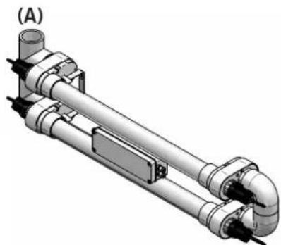
natural_image
3D rendering of a mechanical pipe assembly with cylindrical and U-shaped components (no text or symbols visible)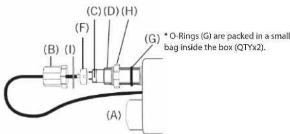
Figure 2. 11405-100 Watt
NOTE: For optimum performance, the electronic ballast has been configured for UV bulbs supplied by AstralPool. When sourcing replacement UV Bulbs or quartz sleeves always buy components supplied by AstralPool from your nearest AstralPool stockist.
Section 5. Flow Rates
| Model Total | No. of 55W Lamps Max Flow Rate | Maximum System Volume (Litres) |
| 1140455 Watt | 1 20,000 55,000 | |
| 1140511 Watt | 2 25,000 75,000 |
Table 4.

Figure 3. Installation Position
Section 6. Installation
6.1 Install the Quartz Sleeve

Figure 4. Quartz Sleeve
- Starting at one end of the unit, unscrew the black end cap (B). This black end cap houses the bulb socket (F).
- Unscrew the white locking nut (H) from the same end.
- Repeat steps 1 and 2 at the other end of the unit.
- Take the quartz sleeve (D) from the packaging box and slide it through the UV until it finds the hole at the far end of the unit.
- Take the quartz sleeve O-Ring (G) and fit it around one end of the quartz sleeve.
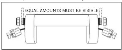
- Slide this quartz sleeve O-Ring (G) towards the thread on the UV body, ensuring that equal amounts of quartz sleeve are visible at each end of the unit.

IMPORTANT: Ensure that equal amounts of the quartz sleeve are visible at each end of the unit before fitting the locking nuts.
- Fit the quartz sleeve O-Ring (G) at the other end of the quartz sleeve, again ensuring that equal amounts of quartz sleeve are visible at each end of the unit.
- Now screw the white locking nut (H) back into position.
- Ensure the locking nut is HAND TIGHTENED to prevent causing damage to the O-Ring. No tools are needed.
- Repeat steps 8 and 9 at the other end of the unit.
- The quartz sleeve is now in position ready to take the UV bulb.
- For all models, complete steps 1 to 4, then run the unit wet, with no bulbs to ensure the quartz sleeves and O-Rings have been installed correctly and are fully water tight. HAND TIGHTEN FITTINGS ONLY - DO NOT USE TOOLS.
6.2 Testing the Quartz, O-Rings and Locking Nuts
Now that the unit is in position and connected to pipework, the quartz sleeve and O-ring at each end can be leak tested to ensure that they have been fitted properly. Failure to test for leaks and improper installation may cause water to seep into and damage the bulb socket and end cap sealing ring.
- Fit quartz sleeve, o-rings and locking nuts.
- Check the locking nuts are hand tight only.

natural_image
Pure mechanical diagram of a cylindrical component with two side connectors (no text or symbols)- Position and mount UV and connect to pipework.

natural_image
Technical line drawing of a mechanical assembly with no visible text or symbols- Turn on pump and pump water through unit.

natural_image
Mechanical assembly diagram showing two connected components with directional arrows indicating movement (no text or labels)- Check locking nuts for signs of water leaking.

natural_image
Technical line drawing of a mechanical assembly with two circular annotations highlighting specific components (no text or symbols present)- If water leaks from locking nuts, review installing the quartz sleeve on page 7.

natural_image
Pure mechanical assembly diagram showing two connected components with downward force arrows and cross symbols (no text or labels)- If no water leaks, quartz sleeve is properly installed.

natural_image
Pure mechanical assembly diagram showing two clamped components with checkmark indicators (no text or symbols)WARNING
Failure to test for leaks and improper installation at this stage may cause water to seep into and damage the bulb socket and ballast. Water damage from improper installation is NOT covered under warranty.
6.3 Install the UV Bulb

Figure 5. UV Bulb
- Remove all packaging from the UV bulb (C).
- Slide the UV bulb (C) carefully through the quartz sleeve (D) that you have just fitted. See 6.1.
- While holding one of the black end caps (B) gently push the cable through the end cap which will make it easier to fit the bulb socket (F) in step 5.
IMPORTANT: Do not pull the cable by holding just the bulb socket.
- The end cap sealing ring (l) is already seated on the inside of the bulb socket.
IMPORTANT: Ensure the end cap sealing ring is not twisted and it remains in this location throughout the installation.
- In no particular order, align the UV bulb pins with the holes in the bulb socket and carefully push the bulb socket firmly onto the UV bulb pins. You may need to hold the other end of the UV bulb to help you fit the socket.
- Ensure the UV bulb socket is firmly connected to the UV bulb.
- Repeat steps 3 to 6 at the other end of the unit.
- Now at one end of the unit, slide the black end cap (checking that the sealing ring in position) over the bulb socket while carefully holding the cable to prevent the bulb connector disconnecting from the UV bulb.
- Screw this end cap onto the thread on the white locking nut (H) already connected to the UV body. HAND TIGHTEN ONLY.
- Repeat steps 8 and 9 at the other end of the unit.
- Check that all of the fittings are hand tightened. No tools are needed.
- On multiple bulb units, do not mix up the bulb connectors as this will result in the bulb not illuminating. HAND TIGHTEN FITTINGS ONLY - DO NOT USE TOOLS.
- Please ensure that there is enough space at one end of the UV to enable bulb / quartz sleeve removal and maintenance.
6.4 Connect to the Electricity Suppy
Electrical installations must be carried out by a qualified electrician. Do not attempt to tamper with or access the electrical control box or casing inside the UV, as doing so will invalidate the warranty.
The power supply must meet the specifications on the product. The cores in the supply cable are coloured in accordance with the following code:
Brown = Live
Blue = Neutral
Earth = Green/Yellow (where fitted)
IMPORTANT: Do not use the supply cable to lift the UV as this may cause damage.
Section 7. Maintenance
7.1 UV Bulb Replacement
Isolate the unit from any electricity and water supplies before carrying out maintenance on the unit. It is not necessary to stop the water through the UV to change the bulb.
Life span of a UV bulb is 9000 hours (approx 1 year continue running). It is recommended that the bulb is changed during this running time.
7.1.1 To Remove a UV Bulb
- Disconnect the electricity supply.
- Unscrew the black end cap at one end of the unit. Take care not to unscrew the white locking nut also.
- Carefully slide the black end cap over the wire to reveal the bulb socket. Do not lose the end cap sealing ring.
- Disconnect the bulb socket.
- Repeat steps 2 to 4 at the other end of the UV.
- With the end caps out of the way, carefully slide out the UV bulb.
7.1.2 To Install a New UV BUIb
- Refer to the installation of the UV Bulb steps in 6.2.
IMPORTANT: After checking all the fittings are correctly tightened you can switch your unit back on.
7.2 Replace / Clean Quartz Supply
Always isolate the unit from any electricity and water supplies before carrying out maintenance on the unit.
7.2.1 To Remove a Quartz Sleeve
NOTE: Removing the quartz sleeve will cause water to flow out of the unit.
- Remove the UV bulb.
- With the electricity supply disconnected, UV isolated and UV Bulb removed, unscrew the locking nut at one end of the UV.
- Water should be drained from the unit.
- Carefully remove the quartz sleeve O-Ring and keep safe.
- Unscrew the locking nut from the other end and remove the quartz sleeve O-Ring and keep safe.
- Carefully remove the quartz sleeve taking care not to allow it to drop inside the UV body.
- To drain any water that may be left in the unit, we would recommend that you unscrew the mounting bracket(s), disconnect the unit from the pipework, and tilt the unit to drain the chamber of water.
- Clean the sleeve and polish with a soft cloth or paper towel. If you live in a hard water area, you may get limescale on the quartz sleeve; this can be easily removed by using vinegar or a cold water descaler.
7.2.2 To Re-Install a Quartz Sleeve
- Refer to the re-installation of the quartz sleeve and UV bulb in 6.1.
IMPORTANT: After checking all the fittings are correctly tightened you can switch your unit back on.
7.2.3 Check for Leaking Water
If you notice water leaking from around the end caps, you should check the following:
- Check the O-Ring is undamaged.
- Check there are no cracks and breaks in the quartz sleeve.
- Check that the locking nut is compressing the O-Ring to form a water tight seal.
- Check that the end caps are sufficiently tight.
- All components are clean and free from dirt and debris.
NOTE: Please note that the items list 1-5 are service items and therefore not subject to a claim under warranty. The service items listed are available from your AstralPool stockist.
Section 8. Troubleshooting
| Issue Solution | |
| - UV BULB NOT LIT- RCD TRIPPED | Check for powerCheck the UV bulb for signs of failure, and replace if necessary.Unscrew the end caps and ensure the correct fittings.Make sure the end caps are dry.11405 Bulbs are electrically linked as a pair. If one bulb fails, both bulbs will not illuminate. Substituting either bulb will identify which bulb has failed.Do not mix up the bulb connectors as this will result in the bulb not illuminating. |
| - LEAKING END CAPS | Make sure the end cap is not damaged or overtightened.Check the quartz sleeve O-Ring, reposition it or if necessary replace it with a new one. |
| - POWER SURGE | Commercial UV sterilisers have thermal overload protection which automatically shuts down and then enables a fast re-start when the problem has been cleared. |
| - TEMPERATURE OVERLOAD | Should the temperature exceed the maximum operating temperature limits, the Thermal Overload Protection will enable itself. |
Section 9. Frequently Asked Questions
How often should I change the UV bulb?
The UV bulb has an effective lifespan of 12 months (9000 hours). This should be changed without fail in order for the unit to remain effective and fit for purpose.
Is the UV suitable for salt water use?
The UV is manufactured from materials that will not corrode in salt water, however the stainless steel bracket will. Use alternative mounting means when using UV on saltwater systems.
How long can I leave the unit running?
UVs have been designed and manufactured to the highest standards, and can be run 24 hours a day. For external applications, if the unit is frost protected it may be left running throughout the winter. Otherwise, the unit should be removed, drained and stored safely for the winter.
Can I bury the unit underground?
No. The UV, although weatherproof, is not suitable for installing in any situation that may be subject to immersion in water.
Can it be used with ozone?
Yes. The UV is safe to use with ozone units, however, the O-Rings are not. When using ozone units please use rigid pipe.
When replacing the bulb I cannot locate it into the bulb socket at the opposite end of the UV?
Please follow the procedure for cleaning / replacing the quartz sleeve. This will explain the correct procedure for removing both end caps and sockets and explain the method for easy installation.
Section 10. Warranty
This product is sold with a limited factory warranty. Detail are included with this product or for full terms and conditions, please visit www.astralpool.com.au
All warranty issues should be resolved with your AstralPool dealer or place of purchase. Claims must include the UV Disinfection System serial number and model (this information can be found on the rating plate), installation date, and name of the installer. Shipping costs are not included in the warranty coverage.
The warranty does NOT cover damage caused by improper assembly, installation, operation or field modification. Also, any damage to the product caused by improper water chemistry will NOT be covered by the warranty.
NOTE: Keep this manual in a safe place for future reference when inspecting or servicing the heater.

For full warranty terms and conditions and to register your warranty, visit www.astralpool.com.au/warranty and complete your details. Or scan the QR code and be taken directly to the registration page
Record your Equipment details here for quick reference:
Model No.: ____
Serial No.:

ASTRAL1020420191MAN
Fluidra Australia Pty Ltd
219 Woodpark Rd
Smithfield, NSW 2164, Australia
1300 763 021
For contact details visit: www.astralpool.com.au
- ASTRALPOOL UV DISINFECTION SYSTEM
- WARNING
- TABLE OF CONTENTS
- Section 1. Important Safety Instructions
- READ AND FOLLOW ALL INSTRUCTIONS
- DANGER
- CAUTION
- Section 2. Product Information
- Energy Consumption
- Disposal Of Your Old Product
- Section 3. Introduction
- The AstralPool UV Disinfection System
- Unboxing the UV
- Section 4. Components
- 11404 - 55 Watt Components
- 11405 - 110 Watt Components
- Section 6. Installation
- Install the Quartz Sleeve
- Testing the Quartz, O-Rings and Locking Nuts
- Install the UV Bulb
- Connect to the Electricity Suppy
- Section 7. Maintenance
- UV Bulb Replacement
- To Remove a UV Bulb
- To Install a New UV BUIb
- Replace / Clean Quartz Supply
- To Remove a Quartz Sleeve
- To Re-Install a Quartz Sleeve
- Check for Leaking Water
- Section 9. Frequently Asked Questions
- How often should I change the UV bulb?
- Is the UV suitable for salt water use?
- How long can I leave the unit running?
- Can I bury the unit underground?
- Can it be used with ozone?
- When replacing the bulb I cannot locate it into the bulb socket at the opposite end of the UV?
- Section 10. Warranty
Brand : ASTRALPOOL
Model : 11405
Category : Système de désinfection UV