
MWH-38P3 - Chauffe-eau instantané et chauffe-eau MIDEA - Free user manual and instructions
Find the device manual for free MWH-38P3 MIDEA in PDF.


| Product Type | Instant Water Heater |
| Model Number | MWH-38P3 |
| Brand | Midea |
| Rated Power | 3800 W |
| Rated Voltage | 220-240 V ~ 50/60 Hz |
| Water Connection | 1/2 inch (G1/2) |
| Max Water Temperature | 60 °C |
| Flow Rate (at ΔT=25°C) | 2.2 L/min |
| Water Pressure Range | 0.02 – 0.6 MPa |
| Dimensions (H × W × D) | 280 × 180 × 100 mm |
| Weight (Net) | 1.8 kg |
| Energy Efficiency Class | A |
| Protection Rating | IPX4 |
| Safety Features | Thermal cut-off, pressure relief valve, anti-scald |
| Installation Type | Under sink or wall mounted |
| Functions | Instant heating, adjustable temperature |
| Maintenance | Periodic descaling recommended |
| Spare Parts Availability | Heating element, thermostat, flow sensor |
Frequently Asked Questions - MWH-38P3 MIDEA
User questions about MWH-38P3 MIDEA
0 question about this device. Answer the ones you know or ask your own.
Ask a new question about this device
Download the instructions for your Chauffe-eau instantané et chauffe-eau in PDF format for free! Find your manual MWH-38P3 - MIDEA and take your electronic device back in hand. On this page are published all the documents necessary for the use of your device. MWH-38P3 by MIDEA.
USER MANUAL MWH-38P3 MIDEA
natural_image
Line drawing of a Midea air purifier device with control knob and buttons (no text or symbols)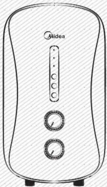
natural_image
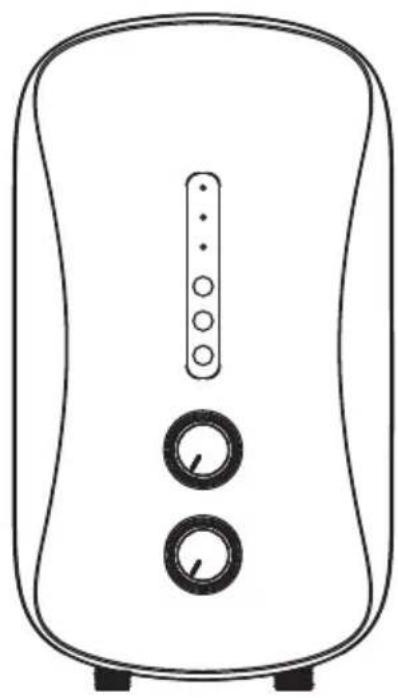
Line drawing of a Midea air fryer with control knobs and a vertical screen (no text or symbols on device body)The diagram above is just for reference. Please take the appearance of the actual product as the standard.
Sincerely thank you for selecting our electric water heater. Please read this manual carefully before use; correctly grasp the methods for installation and use of this electrical water heater, to make full use of its excellent performances. Please do preserve the instruction manual for future reference.
TABLE OF CONTENTS
TITLE PAGE
- Cautions ......(2)
2.Product introduction ....(3) - Unit installation ....(7)
4.Methods of using....(10) - Maintenance....(11)
- Troubleshooting....(12)
1. CAUTIONS
To prevent personal injury, injury to others and property damage, the instructions below must be followed. Incorrect operation due to failure to follow instructions will cause harm or damage. Installation must be carried out by a qualified personnel and in compliance to the local authority regulations.
Special Cautions
- This water heater is for household, and it can be installed wherever place that need hot water.
- Plug is not used for this water heater; this water heater must be connected directly with power switch that comes with leakage-protection. Please distinguish live line (red/brown), neutral line (blue) and earth line (green/yellow) during installation.
- Do check whether the amperes of the household wiring enough before installation, and dedicated circuit must be used when installation.
- Before installing this water heater, check and confirm the earth electrode on the socket is reliably earthed, without electricity.
- The hot water from the water heater may cause scald, please test the temperature of the hot water before use.
- The distance between water heater installed and water output should be as nearby as possible to avoid loss of heat.
- The electric water heater may be damaged if the water hardness is too high. To ensure longer product lifespan, please install and put it into use on condition that the local water hardness is less than 450mg/L (CaCO3)
- In time of lightning/thunder, switch "Off" the Miniature Circuit Breaker (MCB) in advance to protect the water heater against possible damage.
- Inspection on the built-in ELCB (once a month) to avoid a hazard to users such as damage to property, serious injury or death.
- Do cut-off power supply before any maintenance. Any maintenance or adjustment towards this product by non-professional is highly prohibited.
- The damage power cord must be replaced by a good power cord provided by the manufacturer, and the replacement should be done by a qualified technician or engineer or professionals of the similar products.
- In order to avoid a hazard due to inadvertent resetting of the Earth Leakage Circuit Breaker (ELCB), this appliance must not be supplied through an external switching device, such as timer or connected to a circuit that is regularly switched “On” and “Off” by the utility.
- Water heater is equipped with adjustable flow capacity safety valve. For safety use, please do not change its installation location and do not block its water outlet.
- For any improper installation and incorrect operation of this product, our company will not be liable for any responsibility.
- This water heater can be used for other purpose, eg. Washing hands, dishes or foods, and so on. (Multi directional water supply is not available).
- When the shower is used by someone such as child, old person, sick person and physical handicapped person, the concern person is kindly requested to pay attention and check the shower temperature by using hand from time to time.
- The heater must be permanently connected to the electricity supply, direct from the consumer unit via a double poles linked switch with a minimum contact gap of 3mm in both poles. The switch must be readily accessible and clearly identifiable and out of reach of person using a fixed bath or shower. The wiring must be connected to the switch without the use of a plug or socket outlet.

WARNING
The water heater should be earthed before use. Please ensure that the resistance of household earth wire is <4 . Using water heater without earthed is highly prohibited.
2. PRODUCT INTRODUCTION
2.1 Technical Performance Parameters
| Model | MWH-38P3MWH-38P3-RS | MWH-38P5 |
| Rated Voltage | 240V~ | |
| Rated Frequency | 50Hz | |
| Rated Power | 3800W | 3800W |
| Rated Current | 16A | 16A |
| Dia. Of Wire Code | 1.5mm^2 | 1.5mm^2 |
| Air Switch | ≥20A | ≥20A |
| Rated Pressure | 0 MPa | |
| Minimum Flow Rate | 2 Liters/minute | |
| Minimum Pressure | 0.02 MPa | |
| Maximum Pressure | 0.3 MPa | |
| Protection Class | I | |
| Water Proof Class | IP25 | |
| Products Size | 230×406×102 mm | |
| Knob Quantity | 2 | 1 |
2.2 Parts Identification
natural_image
Line drawing of a portable air conditioner with two circular buttons and a vertical indicator (no text or symbols)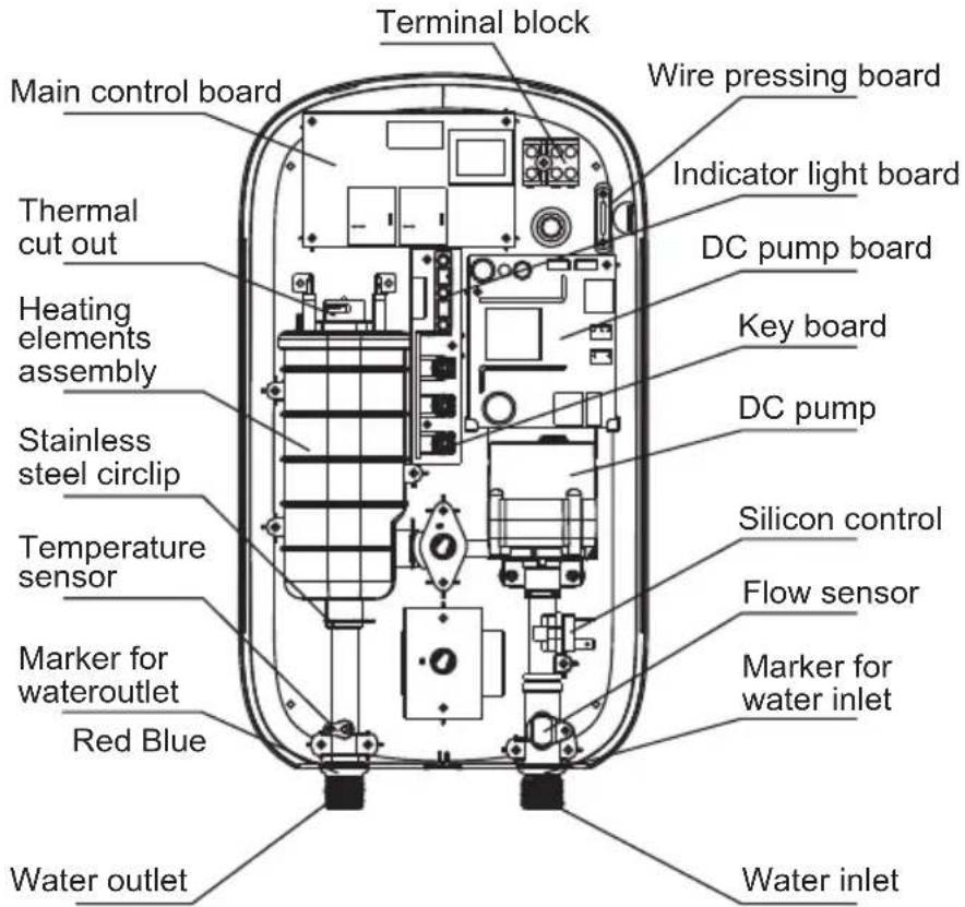

PRODUCT STRUCTURE FOR MWH-38P3 & MWH-38P3-RS
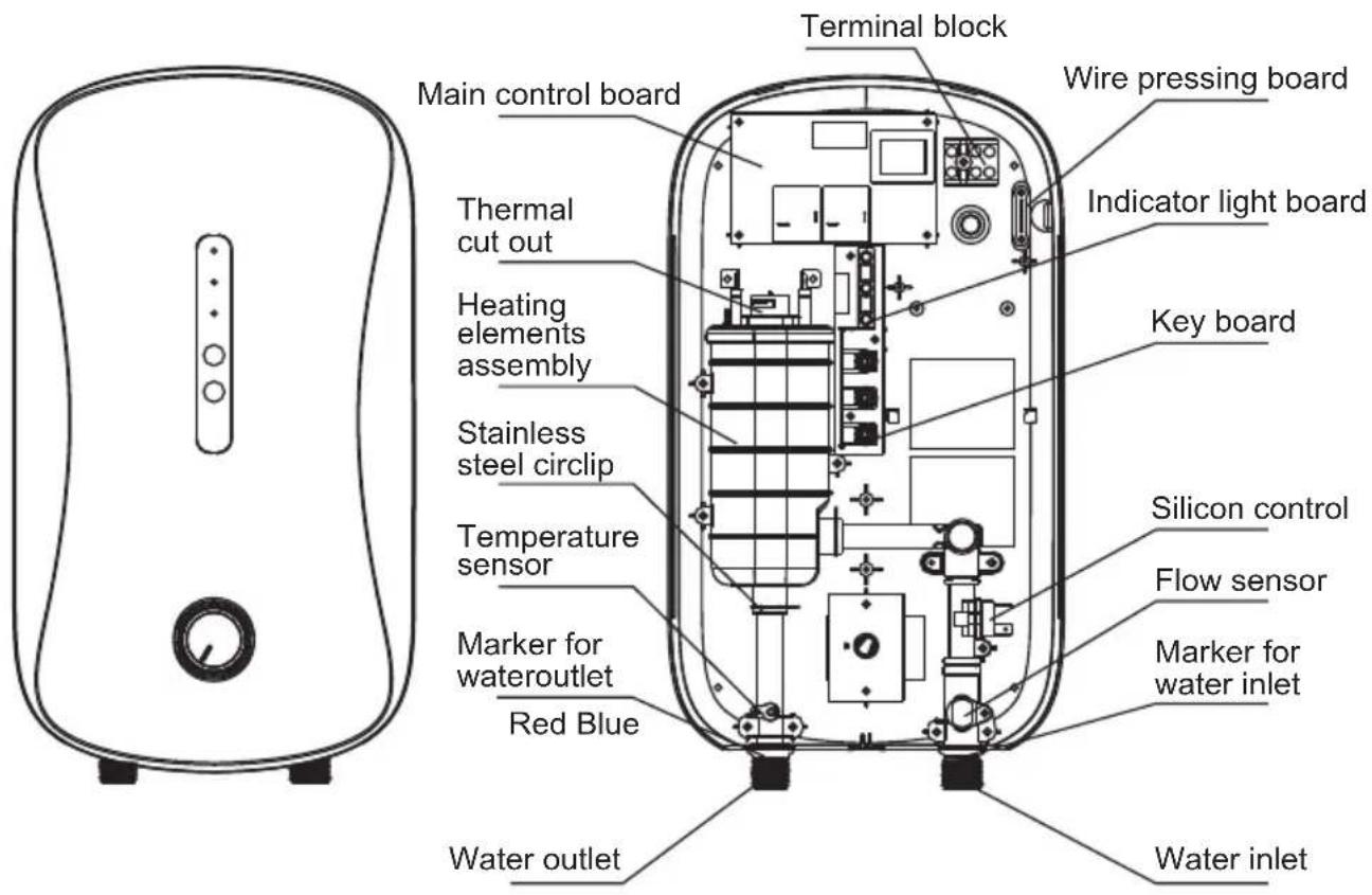

PRODUCT STRUCTURE FOR MWH-38P5
2.4 Internal Wire Diagram
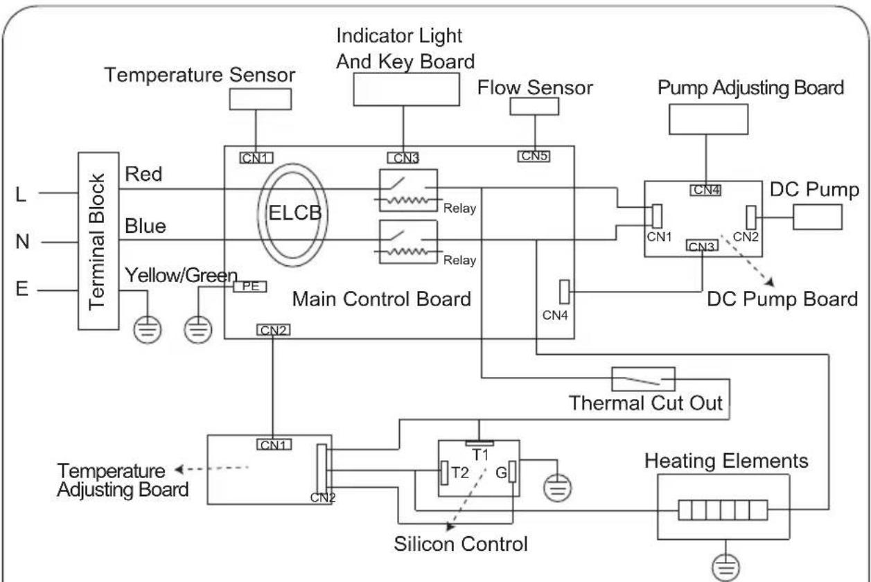
flowchart
graph TD
    A["Temperature Sensor"] --> B["Red"]
    C["Indicator Light And Key Board"] --> D["Blue"]
    D --> E["ELCB"]
    F["Flow Sensor"] --> G["Main Control Board"]
    H["Pump Adjusting Board"] --> I["DC Pump"]
    J["DC Pump Board"] --> K["PC"]
    L["Terminal Block"] --> M["Yellow/Green PE"]
    N["L/N/E"] --> O["Ground"]
    P["CN1"] --> Q["Main Control Board"]
    R["CN2"] --> Q
    S["CN3"] --> T["Main Control Board"]
    U["CN4"] --> V["Main Control Board"]
    W["CN5"] --> V
    X["Temperature Adjusting Board"] --> Y["T1"]
    Z["Heating Elements"] --> AA["Silicon Control"]
    AB["Thermal Cut Out"] --> AC["Main Control Board"]
    AD["REDACTED CON1"] --> AE["Main Control Board"]
    AF["REDACTED CON2"] --> AG["Main Control Board"]
WIRING DIAGRAM FOR MWH-38P3 & MWH-38P3-RS
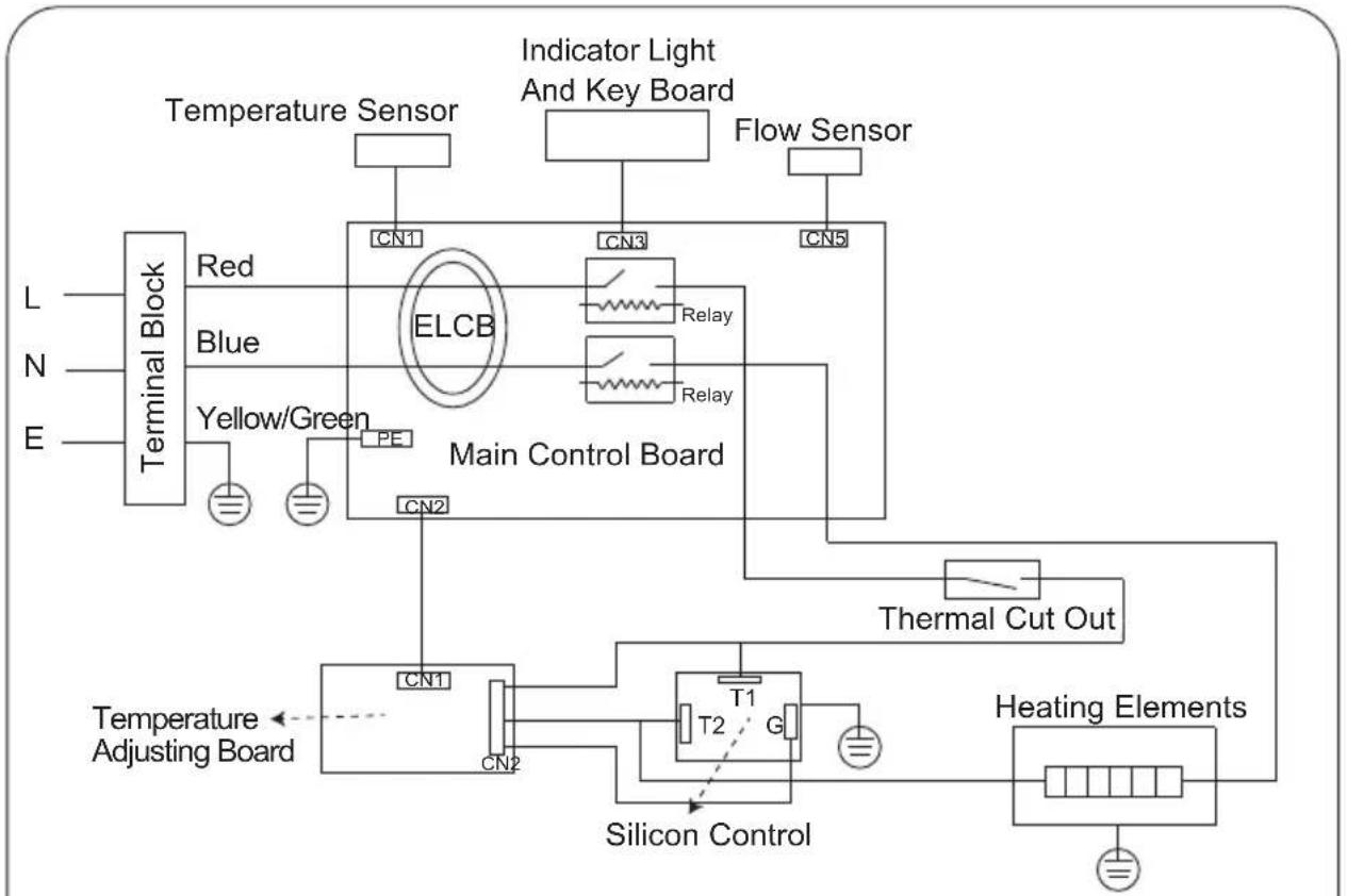
flowchart
graph TD
    A["Terminal Block"] --> B["Red"]
    A --> C["Blue"]
    A --> D["Yellow/Green"]
    B --> E["ELCB"]
    C --> E
    D --> E
    E --> F["Main Control Board"]
    F --> G["CN1"]
    F --> H["CN2"]
    F --> I["CN3"]
    F --> J["CN4"]
    F --> K["CN5"]
    F --> L["Temperature Sensor"]
    F --> M["Indicator Light And Key Board"]
    F --> N["Flow Sensor"]
    F --> O["Thermal Cut Out"]
    P["Temperature Adjusting Board"] --> Q["CN1"]
    P --> R["CN2"]
    S["Temperature Control"] --> T["T1"]
    S --> U["G"]
    V["Heating Elements"] --> W["Ground"]
WIRING DIAGRAM FOR MWH-38P5
3. UNIT INSTALLATION
3.1 Installation Instruction
① Check the capacity of power circuit;
② Power cord installation;
③ Water heater installation;
④ Plumbing connection;
⑤ Power supply connection;
⑥ Water Supply.
3.2 Power Cord Installation
Step 1 Step 2
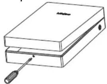
natural_image
Line drawing of a two-tiered electronic device with a screwdriver inserted (no text or symbols)Remove the screws at the bottom of the unit. Lift up the Main Switch Knob and Power Knob to make it free. Remove the front plate gently.
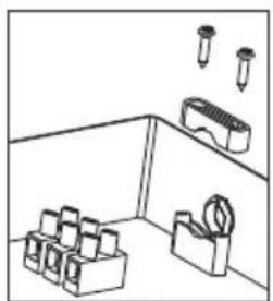
natural_image
Simple line drawing of a room with stacked boxes, a pencil holder, and a brick (no text or symbols)Remove the power cord wire pressing plate and keep the screws.
Step 3 Step 4
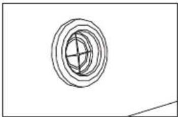
natural_image
Simple line drawing of concentric circles with a central cross, no text or symbols presentGash the middle of the film of the power cord jacket with a sharp knife in order to put into power lines.
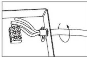
natural_image
Pure mechanical diagram showing a lever mechanism with rotational motion (no text or symbols)Screw the power cord into the jacket for installation of wire pressing plate.
Step 5 Step 6
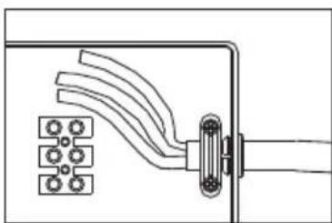
natural_image
Pure electrical circuit lines without any symbolsTighten the wire-pressing plate with screws to primary position, ensure that the power cord not be pulled out more than 60N.
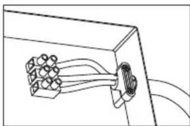
natural_image
Pure diagram of a connector or cable assembly without any text, numbers, or symbolsConnect the power cord to wiring terminals; the method is as shown in picture.

NOTE
The installation position of neutral line (blue), live line (brown/red) and earth line (green/yellow) should be corresponding to the other end on wiring terminals.
3.3 Water Heater Installation
① Determine installation position of the unit according to length of power cord / position of air switch (Distance between bottom and floor should be ≥1.6m).
② Make sure the distance between the unit and surrounding wall is not less than 300mm, so that to have enough space for maintenance purpose.
③ Determinethe position of four fixing screws (attached with the unit), make four holes with corresponding depth in the wall by means of a drill and drive a wall plug into the hole.
④ Drive in the screws on the top and ensure certain distance between screw head and wall (See Fig.1)
⑤ Mount the unit on the wall and tighten with two screws at bottom, connect the wires and install top cover with the screws.
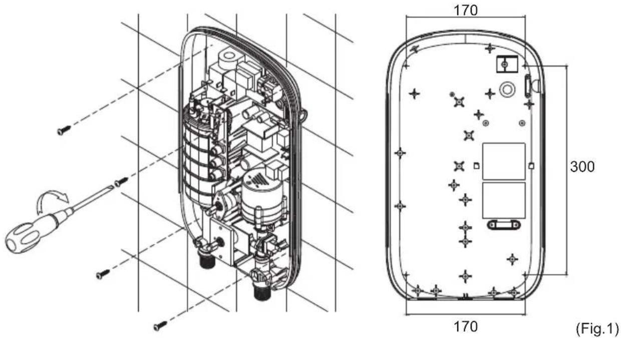
3.4 Plumbing Connection
① Water valve with filter should be installed at water inlet of the unit, sealing ring with filter should be used at end face. (See Fig.2).
② Shower flexible tube should be connected with water outlets and shower head separately, attached sealing ring should be used at end face.

WARNING
Metallic / chromed hose and conductive control valve shall not be used.
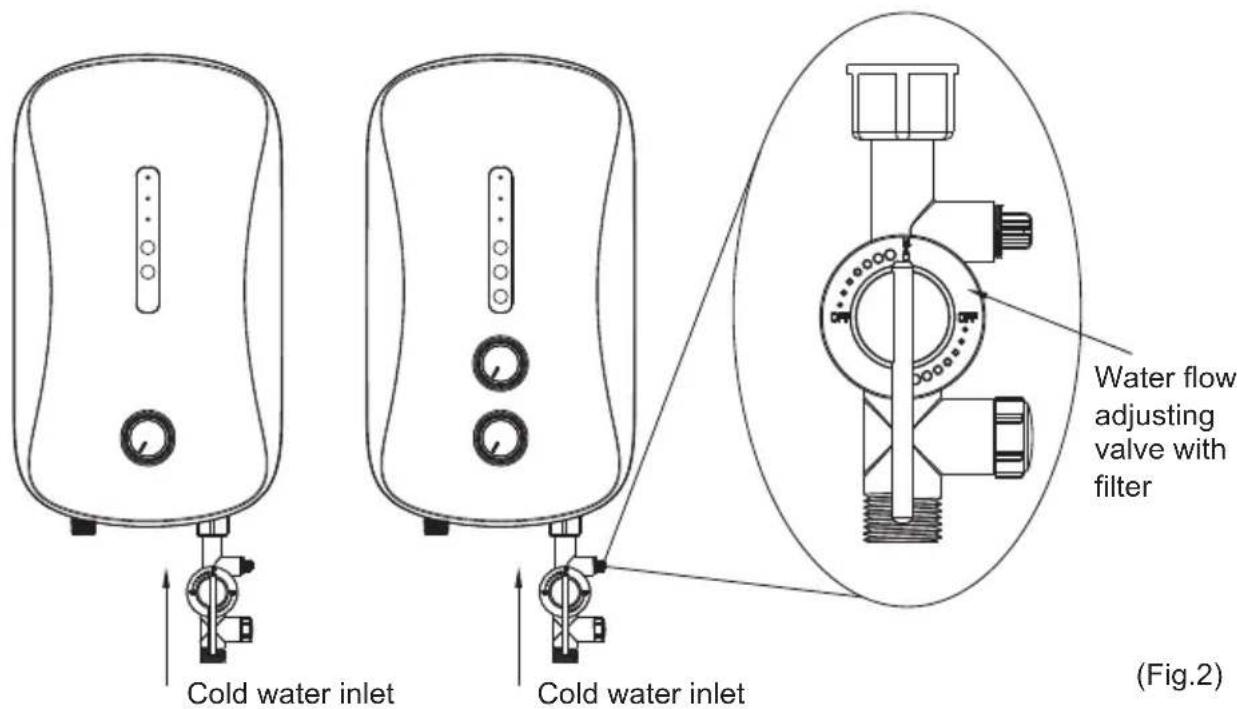
Water flow adjusting valve with filter must be used when install the unit. Blue marker stands for water inlet, red marker stands for water outlet. Do not overexert to avoid damaging the water heater.
3.5 Power Supply Connection
① Adjust power selection knob to "OFF";
② Choose air switch with leakage protection according to power of water heater;
③ When connecting the water heater to electric network, please pay attention to connect live line (red/brown), neutral line (blue) and earth line (yellow/green) with corresponding line in electric network.

NOTE
A private power cord should be used for this unit. After connecting to electric network, please check the earth condition and make sure the earth resistance is <4 .
3.6 Water Supply
After all the plumbing is finished connecting, open water inlet valve of the product and supply water to the unit to drain away air inside until there is stable water flow comes out from shower head. Check whether there is leakage at joints or not. If there is, check whether the connecting parts are fastened or not, then re-supply water.
4. METHODS OF USING
4.1 Operating Of The Unit
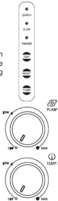
Switch on the power supply, the unit will take self-inspection for 2s, "ELCB" green indicator light will be on (under the condition of no electricity leakage). When the water flow exceeds 1.2L/min, rotate the knob clockwise to switch on heating power rotate switch, heating indicator light will be on, the unit start to work.
4.2 Leakage Testing
When the water heater is working normally (including working state of PUMP), press "TEST" button, if the leakage test circuit is no problem, "ELCB" green indicator light will be off, and the unit will not heat. Press "RESET", testing will be canceled, and "ELCB" green indicator light will be on, the unit will be back to working state set before. If the circuit leaks, press "RESET" button can't cancel leakagetesting, "EARTH"、"ELCB" and "POWER" indicator light is twinkling flicker, it means the water heater has problems and can't be used; all the buttons are invalid, heating is stopped, and pump will be closed.
4.3 To Adjust Water Flow
Rotate the handle of water flow adjusting valve to adjust the water flow.
4.4 Electricity Leakage Protection
When the electricity leakage testing circuit is working normally, if the leakage current is bigger than certain value between 7.5mA and 15mA, "EARTH"、"ELCB" and "POWER" indicator light will be twinkling flicker, no heating; it can only be used after the failure is excluded. (When electricity leakage is tested, red and green indicator lights are all off, stop heating and close the pump system.)
4.5 To Adjust Water Temperature
Rotate the handle of water flow adjusting valve to adjust to proper water flow. Adjust power by rotating knob, clockwise rotate, power will be increased and water temperature increase accordingly or vice versa.
4.6 To Activate Pump Function (For MWH-38P3 & MWH-38P3-RS)
When the unit is working under normal condition, press "PUMP", The pump will start immediately and has been working until the water flow insufficient 1.2L/min for more than 3 seconds.
4.7 To Adjust Water Pressure (For MWH-38P3 & MWH-38P3-RS)
The water pressure is increased when Pump is started; Rotate Pump knob to adjust water pressure, rotate clockwise, water pressure is increased and vice versa.
4.8 Use After Overheating Protection
If the water flow is small and power is high while using the unit, outlet water temperature is rather high; the unit will stop heating automatically. At this time, please lower the power and adjust the water flow faster in order to avoid inconsistency of water temperature.

NOTE
For first time using, ensure electrify after the unit is filled fully with water and there is stable water flow comes out from shower head.
The electric water heater may be damaged if the water hardness is too high. To guarantee the normal service life, please install and put it into use on condition that the local water hardness is less than 450mg/L (CaCO3).
5. MAINTENANCE
- This electric water heater should be installed at the place without sunshine or rain spray. Please cut off power supply if not use for long time.
- Please blow down the water for about 10 seconds to drain away the impurities in the pipe before connecting the water source to the electric water heater to avoid blockage of water heater.
- If long time no use the unit, check the water heater first before use. Electrify after the water flows out stably.
- Do not spray water to air switch or heater body directly, to avoid moist.
- Please cut off the power in the weather of thunder and rain to avoid damaging the water heater.
- If not use for long period of time, please cut off water inlet to prolong the lifespan of the water heater.
- Check the power cord connecting terminals frequently to make sure that they are well and reliably contacted, no overheating phenomenon, and grounding is good or not.
- Disassembly shower head and sealing ring with filter to clean periodically.
DECLARATION: this water heater can only be maintained by authorized service personnel, incorrect installation and using method may cause serious injury or loss of property.

WARNING
Do cut off power supply before maintenance, to avoid danger like electric shock.
6. TROUBLESHOOTING
| SYMPTOMS | REASONS | SUGGESTIONS |
| Switch on the power supply, ELCB indicator light is off. | 1. Power supply error;2. PCB error; | 1. Check whether power is cut2. Contact authorized service personnel for repair. |
| The heating indicator light is off and the outlet water is cold. | 1. The “TEMP” knob is off;2. PCB error;3. The water flow insufficient 1.2L/min;4. Impurities clogging the flow sensor of the rotor | 1. Rotate “TEMP” knob2. Repair or replacement the PCB3. Adjustable water flow4. Change the flow sensor5. Open the flow sensor and clean the rotor |
| The heating indicator light is on and the outlet water is cold. | 1. The thermal cut out is cut off2. Heating elements is broken | 1. Press the reset handle of the thermal cut out after checking and troubleshooting2. Change the heating elements |
| No water flows out from the shower head. | 1. The running water supply is cut off;2. The inlet valve of running water is not open. | 1. Wait for restoration of running water supply;2. Open the inlet valve of running water. |
| Outlet water temperature sometimes is hot, sometimes is cold. | 1. Water pressure is not stable.2. Outlet water temperature is too high, overheating protection again and again. | Adjust the heating power lower, make the water flow bigger. |
| “EARTH”、“ELCB”and “POWER” indicator light is twinkling flicker at the same time | Electricity leaks. | Contact authorized service personnel for repair. |
| Pressure can’t be increased. | PUMP error. | Contact authorized service personnel for repair. |
| “POWER” indicator light is twinkling flicker | Temperture sensor is broken | Change the temperture sensor |
The product is subject to change without notice. Please keep this manual properly.
Panduan Pengguna
Model: MWH-38P3
MWH-38P5
MWH-38P3-RS
natural_image
Line drawing of a Midea air purifier device with control knob and buttons (no text or symbols)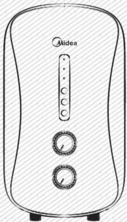
natural_image
Line drawing of a Midea air fryer with control knobs and buttons (no text or symbols)PRODUCT STRUCTURE FOR MWH-38P5
2.4 Diagram Pendawaian
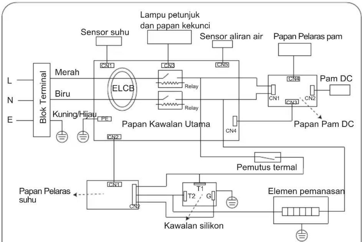
flowchart
graph TD
    A["Blok Terminal"] --> B["Merah"]
    A --> C["Biru"]
    A --> D["Kuning/Hijau"]
    B --> E["ELCB"]
    C --> E
    D --> E
    E --> F["Papan Kawalan Utama"]
    F --> G["Pam DC"]
    F --> H["Papan Pelaras pam"]
    F --> I["Papan Pelaras suhu"]
    F --> J["Elemen pemanasan"]
    F --> K["Pemutus termal"]
    K --> L["T1"]
    L --> M["T2"]
    M --> N["G"]
    N --> O["Kawalan silikon"]
    O --> P["CN1"]
    O --> Q["CN2"]
    P --> R["CN3"]
    Q --> S["CN4"]
    R --> T["Relay"]
    S --> U["Relay"]
    T --> V["Lampu petunjuk dan papan kekunci"]
    U --> W["Sensor aliran air"]
    V --> X["Sensor suhu"]
    W --> Y["Papan Pelaras pam"]
    X --> Z["Pam DC"]
natural_image
Line drawing of a two-tiered electronic device with a screwdriver inserted (no text or symbols)natural_image
Simple line drawing of a room with stacked boxes, a screwdriver, and a brick (no text or symbols)natural_image
Simple line drawing of concentric circles with a central cross, no text or symbols presentnatural_image
Pure mechanical diagram showing a lever mechanism with rotational motion (no text or symbols)natural_image
Pure electrical circuit lines without any symbolsnatural_image
Pure diagram of a connector or cable assembly without any text, numbers, or symbolsnatural_image
Line drawing of a Midea air purifier device with control knob and buttons (no text or symbols)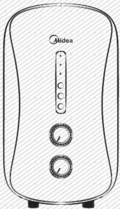
natural_image
Line drawing of a Midea air fryer with control knobs and a vertical indicator (no text or symbols on the device itself)以上图片仅供参考,请以实物为准。
natural_image
Line drawing of a portable air conditioner with two circular control knobs (no text or symbols)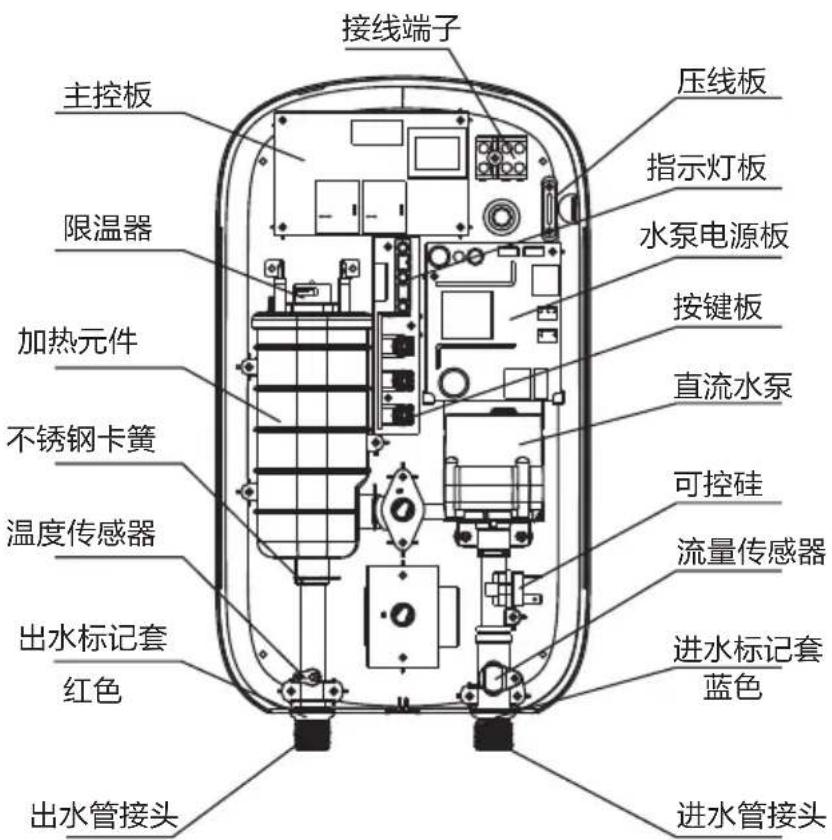
natural_image
Simple line drawing of concentric circles with a central cross, no text or symbols presentnatural_image
Pure electrical circuit lines without any symbolsnatural_image
Pure electrical circuit lines without any symbolsnatural_image
Pure diagram of a connector or cable assembly without any text, numbers, or symbolsnatural_image
Technical line drawing of an internal electrical component with screwdriver and wiring, no text or symbols present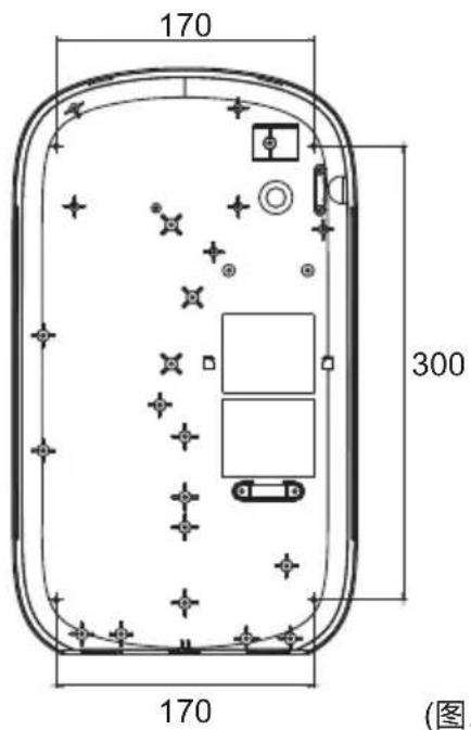
(图.1)
3.4 连接管路

- TABLE OF CONTENTS
- TITLE PAGE
- CAUTIONS
- Special Cautions
- WARNING
- PRODUCT INTRODUCTION
- Technical Performance Parameters
- PRODUCT STRUCTURE FOR MWH-38P5
- UNIT INSTALLATION
- Installation Instruction
- Power Cord Installation
- NOTE
- Water Heater Installation
- Plumbing Connection
- Power Supply Connection
- Water Supply
- METHODS OF USING
- Operating Of The Unit
- Leakage Testing
- To Adjust Water Flow
- Electricity Leakage Protection
- To Adjust Water Temperature
- To Activate Pump Function (For MWH-38P3 & MWH-38P3-RS)
- To Adjust Water Pressure (For MWH-38P3 & MWH-38P3-RS)
- Use After Overheating Protection
- MAINTENANCE
- TROUBLESHOOTING
- Panduan Pengguna
- 连接管路
Brand : MIDEA
Model : MWH-38P3
Category : Chauffe-eau instantané et chauffe-eau