
86801 - Remote control Reflecta - Free user manual and instructions
Find the device manual for free 86801 Reflecta in PDF.


| Product Type | Universal Remote Control |
| Brand | Reflecta |
| Model | 86801 |
| Dimensions (approx.) | 20 x 5 x 2 cm |
| Weight | ~150 g |
| Power Supply | 2 x AAA batteries (not included) |
| Supported Devices | TV, DVD, SAT, etc. |
| Control Type | Infrared (IR) |
| Range | Up to 10 meters |
| Number of Keys | ~40 |
| Main Functions | Power, Volume, Channel, Input, Menu navigation, Numeric keys |
| Programming Method | Auto-search or manual code entry |
| Backlight | No |
| Learning Function | No |
| Material | Plastic |
| Color | Black |
| Maintenance | Clean with a dry cloth; avoid liquids |
| Safety | Keep away from heat sources and water |
| Spare Parts / Repairability | Not repairable; replace if defective |
| General Information | Compatible with most major brands |
Frequently Asked Questions - 86801 Reflecta
User questions about 86801 Reflecta
0 question about this device. Answer the ones you know or ask your own.
Ask a new question about this device
Download the instructions for your Remote control in PDF format for free! Find your manual 86801 - Reflecta and take your electronic device back in hand. On this page are published all the documents necessary for the use of your device. 86801 by Reflecta.
USER MANUAL 86801 Reflecta
(The remote Control is fitted on the CrystalLine Motor Screens series)
Technical Characteristics
Mains Supply: AC200V-AC240V / AC100V-AC120V
Operating Temperature: -10 °C to 50 °C
Motor Control receiver RF 315 MHz / 433 MHz
NOTE: RF 315 MHz rang is not compatible with RF 433 MHz
Mounting of the Receiver (Recommendations)
Install the receiver with the cables entry pointing downwards to avoid water infiltration. Do not install the receiver against or sheltered by a metallic part (it could affect the radio transmission).
Minimum distance between the receiver and the floor: 150cm
Minimum distance between the receiver and the roof : 30cm
Minimum distance between the receiver and the transmitter: 30cm
Minimum distance between two receivers: 20cm
Cabling of the Receiver
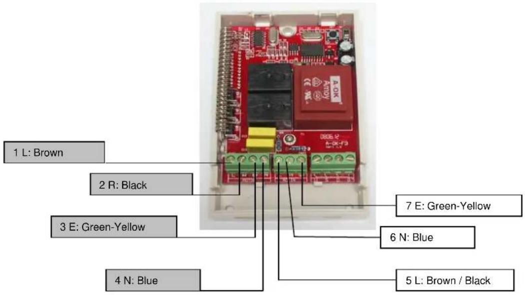
The receiver is compatible with all standard A-OK tubular motors. Cabling arrangements are shown in the diagram below. Respect the electrical standards in force as well as the following points:
- Disconnect the mains supply before carrying out any work
- Be careful to avoid static electricity which could damage some electronic components.
- Use flexible cables
- Ensure that no longitudinal forces act on the cable carriers after installation
- Do not forget to connect the earth wires

Functions
LED 1: Operation LED
KEY: Program setting button
BK1: Selection Switch
Motor: rotation UP / DOWN exchange
BK2: Selection Switch
Embedded switch: UP / DOWN exchange
AC IN - MAINS PLUG
MOTOR – MOTOR CABLE
Program Setting
(4) Press the round button on the emitter to choose the channel needed to be set
(5) Press the setting button (KEY) till the (LED1) light of the receiver begins flashing (the receiver will return to the original state if no operation is done after 10 seconds)
(6) Press the program setting button on the rear of the emitter by ball pen till the LED1 light of the receiver Stops flashing; now program is complete
The receiver can only store 20 channels. If trying to input the 21th channel, the command will be ignored and the LED2 light of the receiver won't flash.
Delete all stored channels' memory from the receiver
(3) Press the program setting button (KEY) of the receiver for about 4 seconds till the (LED1) light begins flashing quickly then loose it
(4) Press this button (KEY) again within six second still the (LED1) light stops flashing. Now all the stored memory of the receiver have been deleted (within 10 seconds, when the LED1 light is flashing quickly. If no operation is done the receiver will return to original state.
Delete the stored memory of any channel
(3) Press the round button on the emitter to choose the channel needed to be deleted
(4) Press the program setting button (KEY) of the receiver till the (LED!) begins flashing. Now the receiver is waiting for the delete command of the emitter
(3) Press the „Down“ button ↓ of the emitter. Now the (LED1) light of the receiver stops flashing means the memory has been deleted (the same way to delete other channels)
Replacing the battery
(4) Open the back board of the emitter with the screwdriver
(5) Take out the old battery and then place the new one in (12V23A Battery)
(6) Close the back board well with the screw (please take the old battery in the appointed place)
Troubleshooting
The LED light of the emitter is off or weak ->
Please check the battery of the receiver
The LED light of the emitter is on, but the command cannot be sent ->
Please check the connection and the receiver or check the programm setting
The LED lights of the emitter and receiver work well but the motor does not work ->
Please check the connection and the main power supply of the motor or check the main power supply.
reflecta gmbh
Merkurstrasse 8
72184 Eutingen i.G.
Germany
www.reflecta.de
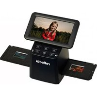
Brand : Reflecta
Model : 86801
Category : Remote control