
SKY-2000 MKII - Receiver Vonyx - Free user manual and instructions
Find the device manual for free SKY-2000 MKII Vonyx in PDF.


| Product Type | UHF Wireless Microphone Receiver |
| Model | SKY-2000 MKII |
| Brand | Vonyx |
| Frequency Range | 600 – 900 MHz (UHF) |
| Number of Channels | Up to 200 selectable |
| RF Output Power | < 10 mW |
| Audio Output | XLR balanced, 6.3 mm unbalanced |
| Dimensions (W x H x D) | 430 x 45 x 180 mm (19" rack, 1U) |
| Weight | 1.8 kg |
| Power Supply | DC 12V, 500 mA (adapter included) |
| Operating Temperature | -10°C to 45°C |
| Antenna Type | External, BNC connectors |
| Display | LCD with channel, frequency, and signal strength |
| Main Functions | Auto-scan, infrared sync, volume control, squelch adjustment |
| Cleaning and Maintenance | Wipe with dry cloth; avoid liquids and aerosols |
| Safety Precautions | Do not expose to rain or moisture; use only supplied power adapter |
| Spare Parts / Repairability | Replaceable antennas, power adapter; consult qualified technician for internal repairs |
| Mounting | 19" rack mount kit included |
| Included Accessories | Power adapter, rack ears, antennas, user manual |
Frequently Asked Questions - SKY-2000 MKII Vonyx
User questions about SKY-2000 MKII Vonyx
0 question about this device. Answer the ones you know or ask your own.
Ask a new question about this device
Download the instructions for your Receiver in PDF format for free! Find your manual SKY-2000 MKII - Vonyx and take your electronic device back in hand. On this page are published all the documents necessary for the use of your device. SKY-2000 MKII by Vonyx.
USER MANUAL SKY-2000 MKII Vonyx
TO PREVENT FIRE OR SHOCK HAZARD, DO NOT EXPOSE THIS APPLIANCE TO RAIN OR MOISTURE.
USE OF CONTROLS OR ADJUSTMENTS OR REFORMANCE OF PROCEDURES OTHER THAN THOSE SPECIFIED HEREIN MAY RESULT IN HAZARDOUS RADIATION EXPOSURE. THE UNIT SHOULD NOT BE ADJUSTED OR REPAIRED BY ANYONE EXCEPT PROPERLY QUALIFIED SERVICE PERSONNEL DOUBLE INSULATED. WHEN SERVICING, USE ONLY IDENTICAL
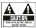
CAUTION:
RISK OF ELECTRIC SHOCK, DO NOT REMOVE THE COVER (OR BACK). THERE ARE NO SERVICEABLE PARTS INSIDE. REFER SERVICING TO QUALIFIED SERVICE PERSONNEL.

The lightning flash with arrowhead symbol, within an equilateral triangle, is intended to er to the presence of un insulated
"dangerous voltage" within the product's enclosure that may be of sufficient magnitude to constitute a risk of electric shock to persons.

The exclamation point within an equilateral triangle is intended to alert the user to the use of important operating and maintenance (servicing) instructions in the literature using the appliance.
NOTE:
This unit may cause interference to radio and television reception
- Handle the power supply cord carefully Do not damage or deform the power supply cord. If it is damaged or deformed, it may cause electric shock or malfunction when used. When removing from wall outlet, be sure to remove by holding the plug attachment and not by pulling the cord.
- In order to prevent electric shock, do not open the top cover. If a problem occurs, contact your dealer.
CAUTION: TO REDUCE THE NOTE:
- Do not place metal objects or spill liquid inside the unit. Electric shock or malfunction may result.
REPLACEMENT PARTS.
Important Safety Instructions
- Read Instructions – All the safety and operating instructions should be read before this product is operated.
- Retain Instructions — The safety and operating instructions should be retained for future reference. 3. Heed Warnings — All warnings on the appliance and in the operating instructions should be adhered to. 4. Follow Instructions — All operating and use instructions should be followed.
- Improper installation can cause serious damage to people and property.
- Water and Moisture — The appliance should not be used near water - for example, near a bathtub, washbowl, kitchen sink, laundry tub, in a wet basement, or near a swimming pool, and the like.
- Carts and Stands — The appliance should be used only with a cart or stand that is recommended by

the manufacturer. An appliance and cart combination should be moved with care.
Quick stops, excessive force, and uneven surfaces may cause the appliance and cart combination to overturn.
- Wall or Ceiling Mounting — The product should be mounted to a wall or ceiling only as recommended by the manufacturer.
- Heat — The appliance should be situated away from heat sources such as radiators, heat registers, stoves, or other appliances (including amplifiers) that produce heat.
- Power Sources – This product should be operated only from the type of power source indicated on the making label. If you are not sure of the type of power supply to your home, consult your product dealer or local power company. For products intended to operate from battery power, or other sources, refer the operating instructions.
- Power-Cord Protection—Power-supply cords should be routed so that they are not likely to be walked on or pinched by items placed upon or against them, paying particular attention to the cord in correspondence of plugs, convenience receptacles, and the point where they exit from the appliance.
- Cleaning - The appliance should be cleaned only as recommended by the manufacturer. Clean by wiping with a cloth slightly damp with water. Avoid getting water inside the appliance.
- Non-use Periods—The power cord of the appliance should be unplugged from the outlet when left unused for a long period of time.
-
Object and Liquid Entry — Care should be taken so that objects do not fall and liquids are not spilled into the enclosure through openings.
-
Damage Requiring Service—The appliance should be serviced by qualified service personnel when:
A. The power-supply cord or the plug has been damaged; or
B. Objects have fallen, or liquid has been spilled into the appliance; or
C. The appliance has been exposed to rain; or
D. The appliance does not appear to operate normally or exhibits a marked change in performance; or E. The appliance has been dropped, or the enclosure damaged.
16. Servicing—The user should not attempt any service to the appliance beyond that described in the operating instructions. All other servicing should be referred to qualified service personnel.
17. Ventilation – Slots and openings in the cabinet are provided for ventilation and to ensure reliable operation of the product and to protect it from overheating, and these openings must not be blocked or covered. The openings should never be blocked by placing the product on a bed, sofa, rug, or other similar surface. This product should not be placed in a built-in installation such as a bookcase or rack unless proper ventilation is the manufacturer's instructions have been adhered to.
18. Attachments – do not use attachments not recommended by the product manufacturer as they may cause hazards.
19. Accessories – Do not place this product on an unstable cart, stand, tripod, bracket, or table. The product may fall, causing serious injury to a child or adult, and serious damage to the product. Use only with a cart, stand, tripod, bracket, or table recommended by the manufacturer, or sold with the product. Any mounting of the product should follow the manufacturer's instructions, and should use a mounting accessory recommended by the manufacturer.
20. Lightning – For added protection for this product during a lightning storm, or when it is left unattended and unused for long periods of time, unplug it from the wall outlet and disconnect the antenna or cable system. This will prevent damage to the product due to lightning and power-line surges.
21. Replacement Parts – When replacement parts are required, be sure the service technician has used replacement parts specified by the manufacturer or have the same characteristics as the original part. Unauthorized substitutions may result in fire, electric shock, or other hazards.
22. Safety Check – Upon completion of any service or repairs to this product, ask the service technician to perform safety checks to determine that the product is in proper operating condition.
Features
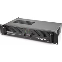
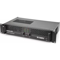
Skytec Professional stereo audio amplifier featuring high output power and excellent value for money. The SKY-MKII range of amplifiers are ideal for the starting DJ, smaller fixed installations in pubs, clubs canteens etc. or as a complement in larger disco installations.
- Outstanding sound quality □ Speaker NL4, 6.3mm Jack & binding post
- Stereo and bridge mode outputs
• Signal & Clip indication for each channel - Inputs via RCA & 6.3mm jack
Front Panel Features

1. On/Off Switch.
For switching the amplifier on and off. Always adjust the volume down to its minimum before switching this amplifier on.
2. Cooling Vents.
Front to rear forced airflow.
3. Volume Controls.
These controls adjust the volume level of both channels. Turn slightly to the left when the clip indicators (4) light up.
4. Signal indicators.
Three orange LEDs indicate the amplifiers output signal levels.
5. Clip lindication.
These LEDs will light up when one or both channels are on max power. It can occur that these LEDs will lit up now and then, this is not a problem. But if it lights up continually you need to adjust the volume down, otherwise permanent damage to equipment might occur
6. Protect Indication.
When on any given point, something damaging might occur to your amplifier, it will switch in protect mode. The amplifier will disconnect the point where the damage is about to occur and switch on the protection led to indicate to you that something is wrong. Reasons might be: Bad ventilation, A low impedance (< 4 Ohm), Defect fan(s), A short circuit in cables.
7. Bridge Mode Indication.
8. Power Indication.
This clear blue indicator will light when the amplifier is turned on.

Rear Panel Features
1. 6.3mm Jack inputs.
Two 6.3mm jack female input connector for connecting a signal source (mixer etc.).
2. RCA inputs.
Two RCA input connector for connecting a signal source (mixer etc.).
3. Mode Switch.
The amplifier can use 2 different modes: stereo & bridge. Choose one of these functions: Stereo mode: Standard left/right stereo mode.
Bridge mode: This mode combines both amps on one channel which results in double power on this channel. Connects the signal to the left input channel and the output level can now be adjusted with the left volume control.
- Ground Lift Switch. Allows circuit and chassis grounds to be separated in case of problems with earth
Installation
Connecting Output
loops (hum)..
-
6.3mm Jack Outputs. Maximum load in stereo mode 4 Ohm per channel.
-
Speaker Outputs NL4. Maximum load in stereo mode 4 Ohm per channel.
Pin +1 & +2 = + output, Pin -1 & -2 = - output
-
Binding Post Output Jacks. Maximum load in stereo mode 4 Ohm per channel. Maximum load in bridge mode 8 Ohm.
-
Mains Power Connector
9. Fuse
This main fuse secures the amplifier and wires against defects. Replace this only with a fuse of same type and value.
Make sure the amplifier is turned off before you wire the system. Speakers can be connected using speaker NL4 plugs or bare wire for your binding post output connectors. Using the guidelines below select the appropriate size of wire bases on the distance between the amplifier and speaker.
| Distance | Wire Size |
| <10m | 1.5mm2 |
| >10m <20m | 2.5mm2 |
| >20m <30m | 4.0mm2 |
Setup operation mode
Amplifier can used in 2 modes:
1. Stereo operation
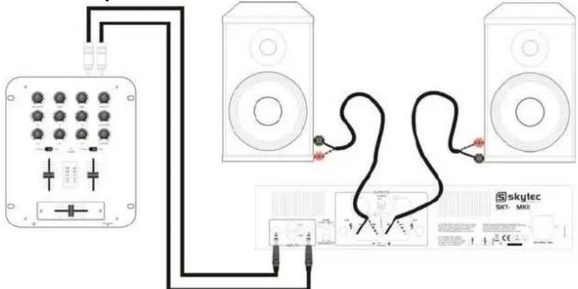
Set the mode selector (3) to the 'stereo' position.
In this mode the amplifier have two independent channels with there own inputs and volume controls.
2. Bridge operation
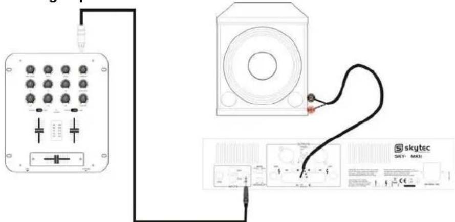
Set the mode selector (3) to the 'bridged' position.
This mode combines both amps on one channel which results in double power on this channel.
Connects the signal to the A input channel and the output level can now be adjusted with the A volume control. Connect the speaker across the positive (+) output terminals. Do not use the negative (-) terminals when the amplifier is being operated in bridged mode.
NOTE: Never connect a hot (+) output to ground or (-) output and never connect the hot (+) to other hot outputs!
Connect to mains power
Before plugging the unit in always make sure that the power supply matches the product specification voltage. First connect the IEC end of the cordset to the IEC connector on the amplifier then plug the other end of the cordset to the AC mains.
Please read instructions below for reliable and problem free use:
- Be sure all connections made are made in the correct way.
- Check if the connected speakers are compatible with the amplifier.
- Ensure there is adequate ventilation.
• Prevent exposure to moisture.
• Never plug speakers in/or out while in use, this can result in serious damage.
Specifications
| Specification | SKY-800III | SKY-1200III | SKY-1500III | SKY-2000III | SKY-3000III | SKY-4000III |
| Ref. No. | 172.050 | 172.052 | 172.054 | 172.056 | 172.058 | 172.060 |
| 4 Ohm Stereo power | 2x400W | 2x600W | 2x750W | 2x1000W | 2x1500W | 2x2000W |
| 8 Ohm Stereo power | 2x240W | 2x400W | 2x450W | 2x600W | 2x900W | 2x1200W |
| 8 Ohm Bridge power | 800W | 1200W | 1500W | 2000W | 3000W | 4000W |
| Frequency range | 10Hz ~ 20kHz (±1.2dB) | |||||
| Dampings factor | >250 | |||||
| Signal to noise ratio (SNR) | >90dB | |||||
| Slew Rate | 30V/uSec | |||||
| Input Sensitivity | 0.77V | |||||
| Input Impedance | 20kOhm | |||||
| Power supply | 220-240Vac / 50Hz | |||||
| Dimensions (bxhxd) | 482 x 314 x 88mm | |||||
Note: Specifications and design are subject to change without notice for purpose of improvement.
This product meets the requirements of the EMC and LVD Directives.
7. Bridge Mode indicator
Zet de Mode-schakelaar (3) in de 'stereo' positie.
Zet de Mode-schakelaar (3) in de 'bridge' positie.
RÜCKSEITE
1. 6.3mm
Klinkene
ingänge
Zwei
6.3mm
Klinkenb
uchsen
zum
Anschlus
S
7. Schraubanschlüsse
natural_image
Diagram showing connections between an audio device and a speaker, with no visible text or symbols.1. Interruptor On/Off.


- CAUTION:
- NOTE:
- Important Safety Instructions
- Features
- On/Off Switch.
- Cooling Vents.
- Volume Controls.
- Signal indicators.
- Clip lindication.
- Protect Indication.
- Bridge Mode Indication.
- Power Indication.
- Rear Panel Features
- 6.3mm Jack inputs.
- RCA inputs.
- Mode Switch.
- Installation
- Connecting Output
- Fuse
- Setup operation mode
- Stereo operation
- Bridge operation
- Connect to mains power
- Please read instructions below for reliable and problem free use:
- Bridge Mode indicator
- RÜCKSEITE
- 6.3mm
- Klinkene
- ingänge
- Schraubanschlüsse
- Interruptor On/Off.
Brand : Vonyx
Model : SKY-2000 MKII
Category : Receiver