
HRW 20 Mono D - Heat pump Thermex - Free user manual and instructions
Find the device manual for free HRW 20 Mono D Thermex in PDF.


| Product Type | Heat Pump (Heat Recovery Ventilation Unit) |
| Brand | Thermex |
| Model | HRW 20 Mono D |
| Power Supply | 220-240 V, 50/60 Hz |
| Control Type | Wired Remote Control (HRW RC D) |
| Speed Settings | 4 speeds: Standby, Minimum, Average, High, Maximum |
| Operating Modes | Heat Recovery, Ventilation, Extraction |
| Boost Function | Yes (maximum speed override) |
| Filter Replacement Indicator | Yes (red LED FILTER) |
| Programmable Filter Intervals | 90, 180, or 365 days |
| Maximum Connected Units | Up to 6 units via single remote control |
| Compatible Environmental Sensors | C TEMP (temperature), C HCS (humidity), C SMOKE (smoke) |
| Remote Inputs | 3 inputs (extraction, recovery, supply at max speed) |
| Power Supply Options | PS24W (wall, up to 4 units), PS36W (wall, up to 6 units), PS36WDIN (DIN rail, up to 6 units) |
| Installation | Must be performed by a qualified technician |
| Safety Compliance | Designed for use by children aged 8+ under supervision |
| Disposal | Compliant with WEEE Directive (do not dispose as household waste) |
| Warranty | 2 years against faulty material or workmanship |
Frequently Asked Questions - HRW 20 Mono D Thermex
User questions about HRW 20 Mono D Thermex
0 question about this device. Answer the ones you know or ask your own.
Ask a new question about this device
Download the instructions for your Heat pump in PDF format for free! Find your manual HRW 20 Mono D - Thermex and take your electronic device back in hand. On this page are published all the documents necessary for the use of your device. HRW 20 Mono D by Thermex.
USER MANUAL HRW 20 Mono D Thermex
Read the instructions contained in this booklet carefully before using the appliance.
Vortice cannot assume any responsibility for damage to property or personal injury resulting from failure to abide by the instructions given in this booklet. Following these instructions will ensure a long service life and overall electrical and mechanical reliability. Keep this instruction booklet in a safe place.
Safety....9
Remote Control Control Panel....10
Setting operating parameters 11
Remote inputs to connect with environmental sensors and/or others Vortice air extractors ..... 12
Mounting schemes 13
Wiring diagrams....13
Important information regarding eco-compatible disposal .... 14
Warning: this symbol indicates that care must be taken to avoid injury to the user
- Follow the safety instructions to prevent any harm to the user.
- Do not use this appliance for purposes other than those described in this manual.
- Having removed the appliance from its packaging, make certain that it is intact and undamaged. If in doubt, consult a professional or contact an authorized Vortice Service Centre.
- Do not leave packaging within reach of children or individuals with disabilities.
- Certain basic rules must always be observed when using any electrical appliance: never touch the appliance with wet or damp hands; never touch the appliance when barefoot.
- Do not operate the appliance in the presence of flammable substances or vapours, such as alcohol, insecticides, petrol, etc.
- If the appliance is to be disconnected from the power supply and no longer used, store it out of reach of children and individuals with disabilities.
• Take precautions to avoid any backdraught of gases into the room from the flue or from other open flame appliances. - This appliance can be used by children no less than 8 years of age and by individuals with limited physical, sensory or mental capacities, or by inexperienced or untrained individuals, provided that they are supervised or have been instructed in safe use of the appliance and understand the associated risks. Children must not play with the appliance. Cleaning and maintenance procedures - for which the user is responsible - must not be carried out by children unless supervised.
Caution:

this symbol indicates that care must be taken to avoid damaging the appliance
- Do not make modifications of any kind to this appliance.
- The maintenance instructions must be followed to ensure the appliance does not suffer damage and/or excessive wear.
- Do not expose this appliance to the elements (rain, sun, etc.).
- Do not stand objects on the appliance.
- The inside of the appliance must be cleaned only by a skilled professional.
- Inspect the appliance periodically for visible defects. If the appliance is defective in any way, do not use it; contact a Vortice authorized Technical Support Centre without delay.
- If the appliance does not function correctly or develops a fault, contact a Vortice authorized Technical Support Centre without delay. Ensure that only genuine original Vortice spares are used for any repairs.
- Should the appliance be dropped or suffer heavy impact, have it checked without delay by a Vortice authorized Technical Support Centre.
- The appliance must be installed in such a way as to ensure that under normal operating conditions, no one can come into contact with any moving parts or live electrical components.
- In the event of: dismantling the appliance with the appropriate tools, removing the heat exchanger or removing the motor module, the appliance must first be switched off and disconnected from the electrical power supply.
- The electrical system to which the appliance is connected must comply with current regulations.
- Connect the appliance to the electrical power supply/socket only if the rated power of the supply is compatible with the maximum rated power of the appliance. If not, contact a professional electrician without delay.
- Turn off the appliance at the main switch: if the appliance does not function correctly, before cleaning the outside of the appliance, or if the appliance is not going to be used for any length of time.
- The flow of extracted air must be clean (i.e. free of grease, soot, chemical and corrosive agents and explosive or flammable mixtures).
- Keep the air intake and outlet ports of the appliance free of obstructions, to ensure optimum air flow.
- The appliance must be installed by a professionally qualified technician.
Remote Control Control Panel
Fig. 1
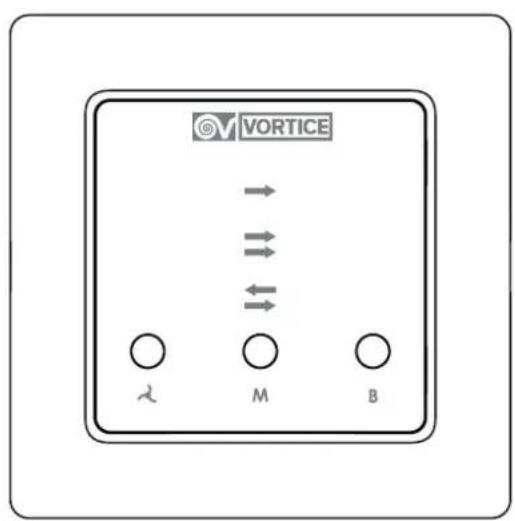
The appliance is controlled via wired Remote Control.
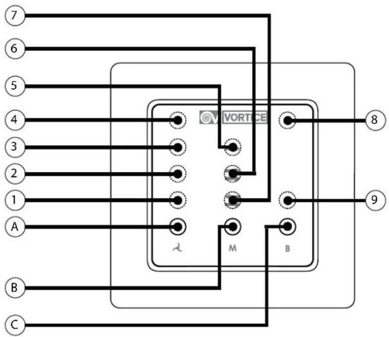
The Remote Control manages from 1 to 6 devices. The Control panel is equipped with the following controls (fig.1):
Buttons:
Ⓐ = button SPEED;
⑧ = button MODE;
© = button BOOST;
LEDs:
- ^A SPEED button: airflow selector
Press repeatedly to select speeds:
- 0: Stand-by/fans off (LED 1+ LED 2 + LED 3 + LED 4: off);
- 1: Minimum flow rate (LED 1: on);
- 2: Average flow rate (LED 1 + LED 2: on);
- 3: High flow rate (LED 1 + LED 2 + LED 3: on);
- 4: Maximum flow rate (LED 1 + LED 2 + LED 3 + LED 4: on);
- Ⓑ= MODE button: fan mode selector
Press repeatedly to select modes:
- RECOVERY (LED RECOVERY: on);
- VENTILATION (LED VENTILATION: on);
- EXTRACTION (LED EXTRACTION: on).
- Ⓐ= BOOST button: max speed selector
Press repeatedly to select modes:
- BOOST on (BOOST LED + LED 1 + LED 2 + LED 3 + LED 4: on);
- BOOST off (BOOST LED + LED 1 + LED 2 + LED 3 + LED 4: off).
Heat recovery mode
Winter: Extracted air from the room (hot) is exploited to pre-heating the air supplied to the room (cold).
Summer: Extracted air from the room (cold) is exploited to pre-cooling the air supplied to the room (hot).
The connected devices cyclically reverse the direction of fan rotation (extracting and introducing air into the environment) with a set cycle time.
Speed adjustment (of devices) is automatic and ensures the correct balance of the Input/Output flow rates.
Further information on cycle time is provided in the paragraph "Setting operating parameters" under "Selecting cycle time".
Ventilation Mode
The devices change internal environment air (without recovering heat).
- Even number devices extract air from the environment.
- Odd number devices introduce air into the environment.
Speed adjustment (of devices) is automatic and ensures the correct balance of the Input/Output flow rates.
Further information on EVEN and ODD number devices is provided in the paragraph "Setting operating parameters" under "Selecting the number of devices to be checked".
Air Extraction Mode
All connected devices extract air from the internal environment.
The air flow rates are all in Output toward the external environment.
ENGLISH
Only for VENTILATION or RECOVERY modes:
In the event that 2,3,4,5,6 units are connected to the Remote Control, these units will be piloted so as to ensure the balance of the overall flow in ventilation mode with heat recovery.
In the case of “ODD Number” connected units (3/5), system balancing may require 2 units to be stopped, in rotation (depending on the speed setting). Further informations about “EVEN/ODD units number” are provided in the paragraph "Setting operating parameters", under “Selecting the number of devices to be controlled”).
Warning: filter replacement
Fig. 2
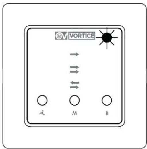
After the scheduled amount of filter replacement time (90,180,365 days), the steady LED FILTER light (red) will light up on the remote control display (without locking the device):
- LED FILTER off: filters clean;
- LED FILTER steady on: filters to be cleaned or replaced.
Further informations are provided in the paragraph "Setting operating parameters", under "Programming filter replacement".
Resetting the warning: filter replacement
The filter replacement warning (red steady on LED FILTER) must be reset after filter cleaning/replacement.
To reset the clogged filter counter:
o Simultaneously press the Speed - Mode - Boost buttons;
o Press the buttons Speed - Speed - Mode - Mode - Boost - Boost in sequence;
o Press any button without 30sec;
o The red LED FILTER will flash briefly to indicate reset has occurred and the machine will return to normal operation.
Important: if no button is pressed within 30sec, the BOOST LED (blue) will flash and the machine will return to normal operation without having first reset the filter timer.
Optionals complete list (not included):
| Description Code Note | ||
| Remote Control - Items | ||
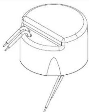
| PS24W 21.187 Power supply for wall mounting - up to 4 units | ||
| PS36W 21.188 Power supply for wall mounting - up to 6 units | ||
| PS36WDIN 21.189 Power supply for electrical panel (DIN bar) - up to 6 units | ||
| Environmental sensors | ||
| C TEMP 12.992 Temperature sensor | ||
| C HCS 12.994 Humidity sensor | ||
| C SMOKE 12.993 Smoke sensor | ||
Setting operating parameters
It is possible to program some device operating parameters by means of corresponding control combinations, as described below:
- To enter into "programming mode":
o Simultaneously press the Speed - Mode - Boost buttons;
o The steady red FILTERS LED will light up;
o Press the buttons Speed - Speed - Mode - Boost - Boost - Mode in sequence;
- Selecting the number of devices to be controlled:
Before continuing, verify the number of devices installed:
o SINGLE unit (1);
o EVEN units (2 or 4 or 6);
o ODD units (3 or 5);
Important: set the number of devices actually installed to ensure Input/Output flow rate balancing.
ENGLISH
After entering "programming mode," press the Speed button to enter "Selecting the number of devices to be controlled mode".
The number of devices currently set will be displayed according to the rule:
o SINGLE unit = LED 1 on
o Number Units: EVEN = LED 2 on
o Number Units: UNEVEN = LED 3 on
- To edit the value: press the Speed button repeatedly.
- To confirm: press the Boost button; The FILTERS LED (red) will briefly flash, indicating that storage was successful and the machine will return to normal operation
Important: if the Boost button is not pressed (for confirmation) within 30sec, the BOOST LED (blue) will flash and the machine will return to normal operation without storing.
- Selecting cycle time:
After entering "programming mode," press the Mode button to enter "Selecting the cycle time mode".
The cycle time currently set will be displayed according to the rule:
o Cycle time 50 seconds = LED 1 on
o Cycle time 80 seconds = LED 2 on
o Cycle time 100 seconds = LED 3 on
- To edit the value: press the Speed button repeatedly.
- To confirm: press the Boost button; The red FILTERS LED will briefly flash, indicating that storage was successful and the machine will return to normal operation.
Important: if the Boost button is not pressed (for confirmation) within 30sec, the BOOST LED (blue) will flash and the machine will return to normal operation without storing.
- Programming filter replacement:
Recommended maintenance timetable: in general the level of air pollution depends on the geographical installation area, and therefore filter duration is variable.
After entering "programming mode," press the Boost button to enter "Programming filter replacement mode".
The time currently set will be displayed according to the rule:
o Filter replacement 90 days = LED 1 on
o Filter replacement 180 days = LED 2 on
o Filter replacement 365 days = LED 3 on
- To edit the value: press the Speed button repeatedly.
- To confirm: press the Boost button; The red FILTERS LED will briefly flash, indicating that storage was successful and the machine will return to normal operation.
Important: if the Boost button is not pressed (for confirmation) within 30sec, the BOOST LED (blue) will flash and the machine will return to normal operation without storing.
Remote inputs to connect with environmental sensors and/or others Vortice air extractors
Fig. 7
Connecting with environmental sensors
It is possible to control devices VORT HRW 20 MONO D from a distance by means of environmental sensors (optional).
The environmental sensors foreseen for unit VORT HRW 20 MONO D are as follows:
- C TEMP = temperature sensor;
- C HCS = humidity sensor;
- C SMOKE = smoke sensor.
Environmental sensors can be connected to the Remote Control by means of clean On/Off contacts on the Remote inputs: #1, #2 and #3 present on the circuit board:
- Remote Input #1 - Air extraction at maximum speed;
- Remote Input #2 - Heat recovery at maximum speed;
- Remote Input #3 - Air supply at maximum speed.
These modes will be activated independently of the current speed settings.
Connecting with others Extractors
To compensate extracted airflows, others Vortice air extractors can be connected to devices VORT HRW 20 MONO D.
Others Vortice air extractors can be connected to the Remote Control by means of clean On/Off contacts on the Remote input # 3 present on the circuit board:
- Remote Input #3 - Air supply at maximum speed.
This mode will be activated independently of the current speed settings.
ENGLISH
Remote Input #1 - "Air extraction at maximum speed mode"
2-pole spring clamp from PCB (IN#,COM), 12Vdc, suitable for cables with maximum cross-section 1.5mm2.
When the contact is closed, all connected devices will work to extract air from the environment at maximum speed:
- Boost on =LED BOOST + LED 1 + LED2 + LED 3 + LED 4: on;
- Extraction on =EXTRACTION LED: on.
Keeping the function on, the LEDs will switch off automatically after 20 seconds.
Remote Input #2 - "Heat recovery at maximum speed mode"
2-pole spring clamp from PCB (IN#,COM), 12Vdc, suitable for cables with maximum cross-section 1.5mm2.
When the contact is closed, all connected devices will work to recover heat at maximum speed:
- Boost on =LED BOOST + LED 1 + LED2 + LED 3 + LED 4: on;
- Recovery on = RECOVERY LED: on.
Keeping the function on, the LEDs will switch off automatically after 20 seconds.
Remote Input #3 - "Air supply at maximum speed mode"
2-pole spring clamp from PCB (IN#,COM), 12Vdc, suitable for cables with maximum cross-section 1.5mm2.
When the contact is closed, all connected devices will work to supply air into the environment at maximum speed:
- Boost on =LED BOOST + LED 1 + LED2 + LED 3 + LED 4: on.
Keeping the function on, the LEDs will switch off automatically after 20 seconds.
Mounting schemes
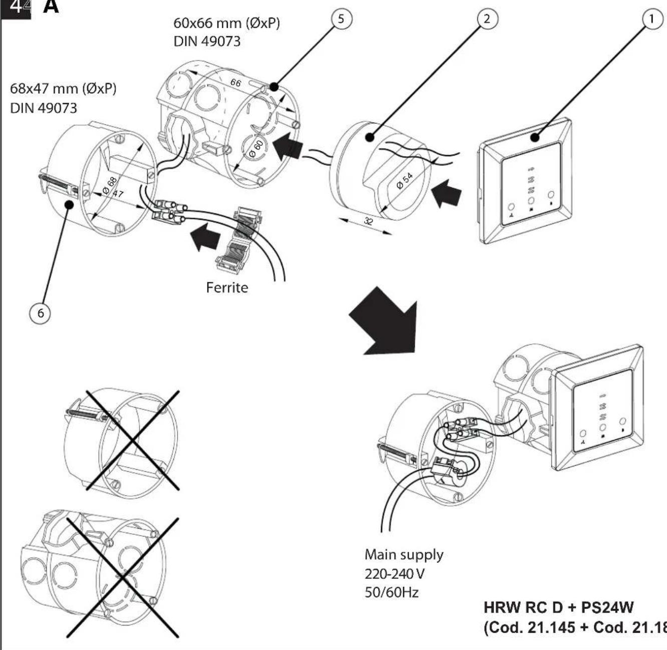
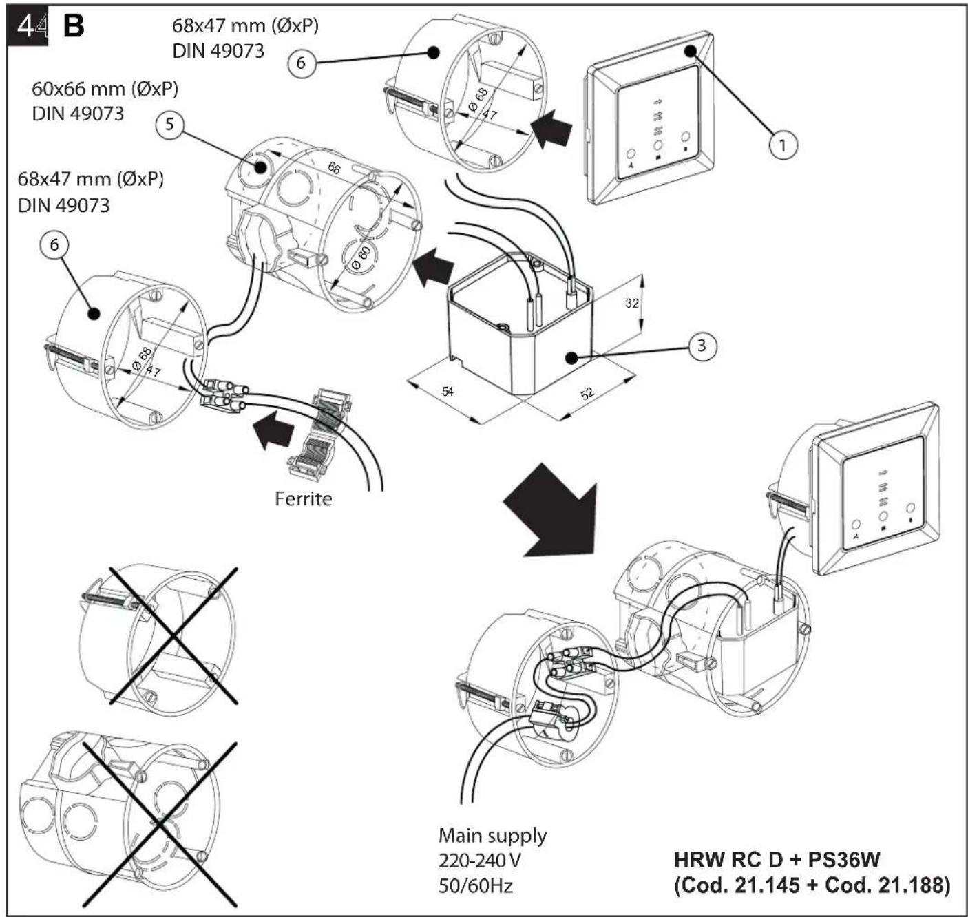
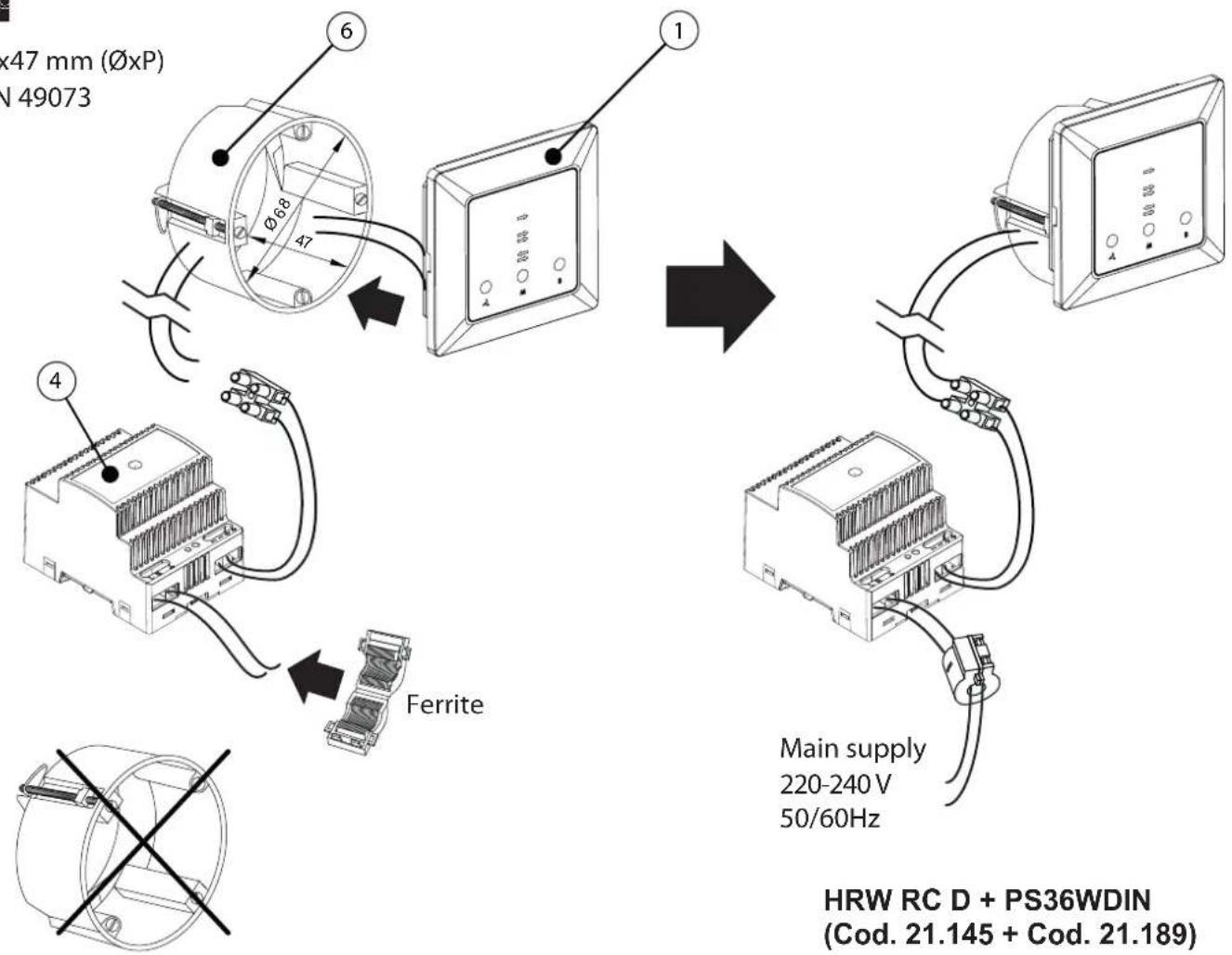
- Mounting with Transformer for wall mounting:
- Up to 4 controlled units: See Fig. 4A;
- Up to 6 controlled units: See Fig. 4B;
- Mounting with Transformer for electrical panel:
• See Fig. 5.
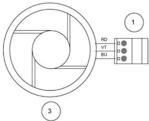
Wiring diagrams
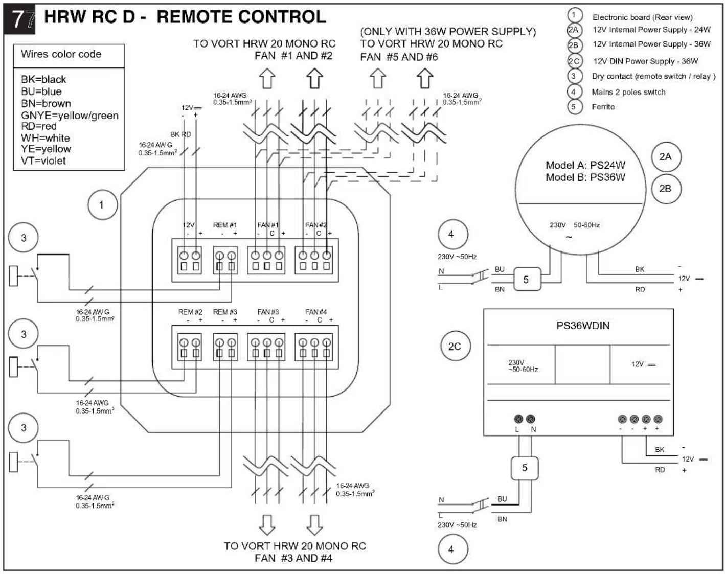
See fig.6 - 7
- Appliance: Vort HRW 20 Mono D (See Fig. 6)
- Remote Control: HRW RC D (See Fig. 7)
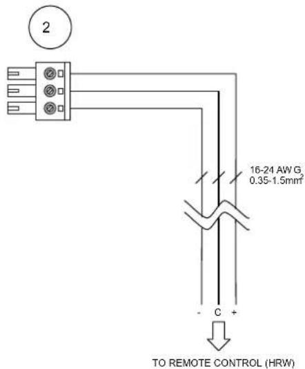
②A electric diagram for wall mounting - up to 4 controlled units;
②B electric diagram for wall mounting - up to 6 controlled units;
② electric diagram for DIN electric panel - up to 6 controlled units;
ENGLISH
Important information concerning the environmentally compatible disposal
IN CERTAIN EUROPEAN UNION COUNTRIES THIS PRODUCT DOES NOT FALL WITHIN THE REQUIREMENTS OF THE NATIONAL LAWS IMPLEMENTING DIRECTIVE WEEE, AND IN THESE COUNTRIES THE PRODUCT IS NOT SUBJECT TO SEPARATE DISPOSAL OPERATIONS AT THE END OF ITS WORKING LIFE.
This product conforms to EU Directive2002/96/EC.
This appliance bears the symbol of the barred waste bin. This indicates that, at the end of its useful life, it must not be disposed of as domestic waste, but must be taken to a collection centre for waste electrical and electronic equipment, or returned to a retailer on purchase of a replacement.
It is the user's responsibility to dispose of this appliance through the appropriate channels at the end of its useful life. Failure to do so may incur the penalties established by laws governing waste disposal.
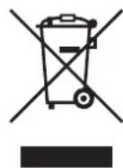
Proper differential collection, and the subsequent recycling, processing and environmentally compatible disposal of waste equipment avoids unnecessary damage to the environment and possible related health risks, and also promotes recycling of the materials used in the appliance.
For further information on waste collection and disposal, contact your local waste disposal service, or the shop from which you purchased the appliance.
Manufacturers and importers fulfil their responsibilities for recycling, processing and environmentally compatible disposal either directly or by participating in collective systems.
Sicherheit

Achtung:
Vortice Elettrosociali S.p.A. reserves the right to make improvements to products at any time and without prior notice.
Building 19, No.388 West Huanghe Road, Xinbei District,
Changzhou, Jiangsu Province CAP:213000
CHINA
vortice-china.com
vortice@vortice-china.com
1
flowchart
graph TD
    A["Terminal A"] -->|Pin 1| VortICE["VORTICE"]
    B["Terminal B"] -->|Pin 2| VortICE
    C["Terminal C"] -->|Pin 3| VortICE
    D["Terminal D"] -->|Pin 4| VortICE
    E["Terminal E"] -->|Pin 5| VortICE
    F["Terminal F"] -->|Pin 6| VortICE
    G["Terminal G"] -->|Pin 7| VortICE
    H["Terminal H"] -->|Pin 8| VortICE
    I["Terminal I"] -->|Pin 9| VortICE
    J["Terminal J"] -->|Pin 10| VortICE
    K["Terminal K"] -->|Pin 11| VortICE
    L["Terminal L"] -->|Pin 12| VortICE
    M["Terminal M"] -->|Pin 13| VortICE
    N["Terminal N"] -->|Pin 14| VortICE
    O["Terminal O"] -->|Pin 15| VortICE
    P["Terminal P"] -->|Pin 16| VortICE
    Q["Terminal Q"] -->|Pin 17| VortICE
    R["Terminal R"] -->|Pin 18| VortICE
    S["Terminal S"] -->|Pin 19| VortICE
    T["Terminal T"] -->|Pin 20| VortICE
2
3
natural_image
Diagram showing a mechanical assembly with an upward arrow and two base supports (no text or symbols)
natural_image
Simple line drawing of a two-tiered table or table with no text, numbers, or symbols44 A
5
68x47 mm (∅xP)
DIN 49073
flowchart
graph TD
    A["Main supply 220-240 V, 50/60Hz"] --> B["Ferrite"]
    B --> C["Switch 1"]
    C --> D["Switch 2"]
    D --> E["Switch 3"]
    E --> F["Switch 4"]
    F --> G["Switch 5"]
    G --> H["Switch 6"]
    H --> I["Main supply 220-240 V, 50/60Hz"]
    style A fill:#f9f,stroke:#333
    style B fill:#ccf,stroke:#333
    style C fill:#cfc,stroke:#333
    style D fill:#fcc,stroke:#333
    style E fill:#cff,stroke:#333
    style F fill:#ffc,stroke:#333
    style G fill:#cfc,stroke:#333
    style H fill:#fcc,stroke:#333
    style I fill:#ffc,stroke:#333
HRW RC D + PS36WDIN
(Cod. 21.145 + Cod. 21.189)
6⑥
VORT HRW 20 MONO D
| 12 V Power supply - list | Sensor - list | ||||||
 |  | 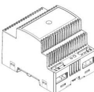 | 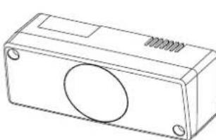 | ||||
| PS24W | 21.187 | PS36W | 21.188 | PS36WDIN | 21.189 | C TEMP | 12.992 |
| C HCS | 12.994 | ||||||
| C SMOKE | 12.993 | ||||||

natural_image
Empty white rectangle with black border (no text or symbols)TIMBRO CENTRO ASSISTENZA
STAMP OF TECHNICAL ASSISTANCE CENTRE - CACHET SERVICE APRES-VENTE



natural_image
Empty white rectangle with black border (no text or symbols)TIMBRO CENTRO ASSISTENZA
STAMP OF TECHNICAL ASSISTANCE CENTRE - CACHET SERVICE APRES-VENTE


natural_image
Empty white rectangle with black border (no text or symbols)TIMBRO CENTRO ASSISTENZA
STAMP OF TECHNICAL ASSISTANCE CENTRE - CACHET SERVICE APRES-VENTE



natural_image
Empty white rectangle with black border (no text or symbols)TIMBRO CENTRO ASSISTENZA
STAMP OF TECHNICAL ASSISTANCE CENTRE - CACHET SERVICE APRES-VENTE

This guarantee is offered as an extra benefit and does not affect your legal rights. All electrical appliances produced by Vortice are guaranteed by the Company for two years against faulty material or workmanship.
If any part is found to be defective in this way within the first twenty months four from the date of purchase or hire purchase agreement, we or our authorised service agents, will replace or at our option repair that part without any charge for materials or labour or transportation, provided that the appliance has been used only in accordance with the instructions provided with each appliance and has been not connected to an unsuitable electricity supply, or subjected to misuse, neglect or damage or modified or repaired by any person not authorised by us. The correct electricity supply voltage is shown on the rating plate attached to the appliance.
This guarantee is normally available only to the original purchaser of the appliance, but the Company will consider written applications for transfer.
Should any defect arise in any Vortice product and a claim under guarantee become necessary, the appliance should be carefully packed and returned to your approved Vortice stockist. This portion of the guarantee should be attached to the appliance.
ITALIA
in sealed envelope to:
Vortice Limited
Beeches House
Eastern Avenue
Burton on Trent
DE13 0BB United Kingdom
IauthorizeVortice
Ltd. to include my
personal details
within their database,
which they use, via a
third party for the
despatch of
advertising material,
at any time, in
accordance
with the regulations in
force within my
country.
I can have access
to my details and can
request changes, or
prohibit the usage of
my details. This will be
done by addressing
my request directly to
Vortice Limited
Beeches House
Eastern Avenue
Burton on Trent
DE13 0BB United
Kingdom.
OTHER COUNTRIES
Please send the guarantee to the retailer's address in the country where the appliance has been purchased.

I authorize Vortice
distributors to include
my personal details
within their database
and they can use it
through a third party
for the despatch of
advertising material.
At any time, in
accordance with the
regulations in force
within my country. I
can have access to
details and can ask to
make changes, or
prohibit the usage o
my details.This will be
done by addressing
my request directly to
the headquarters of
the local distributor
where the appliance
has been bought.

Non autorizzo
(barrare se interessa).

Idonotaauthorize
(please tick if
required).

Idonotaauthorize
(please tick if
required).
1 GARANZIA-GUARANTEE-GARANTIE
DACONSERVARE
TOBERETAINED
ACONSERVER
Thiswarrantymustbeattachedtotheappliancesshoulditneedtobereturnedfor servicing.
N.B. Guarantee is only valid if all details are completed correctly.
TOSEND(within8daysfromdateofpurchase)
cap/postcode/codepostal
città/t o w n
firma/signature/signature
SPEDITOIL
MAILINGDATE-ENVOYÉPARLAPOSTELE
ACQUISTATOIL
DATE OF PURCHESE - DATE DE L'ACHAT
natural_image
Empty white rectangle with black border (no text or symbols)- Warning: this symbol indicates that care must be taken to avoid injury to the user
- Caution:
- this symbol indicates that care must be taken to avoid damaging the appliance
- Remote Control Control Panel
- Fig. 1
- - A SPEED button: airflow selector
- - Ⓑ= MODE button: fan mode selector
- - Ⓐ= BOOST button: max speed selector
- Heat recovery mode
- Ventilation Mode
- Air Extraction Mode
- ENGLISH
- Warning: filter replacement
- Fig. 2
- Resetting the warning: filter replacement
- Setting operating parameters
- - Selecting cycle time:
- - Programming filter replacement:
- Remote inputs to connect with environmental sensors and/or others Vortice air extractors
- Connecting with others Extractors
- Remote Input #1 - "Air extraction at maximum speed mode"
- Remote Input #2 - "Heat recovery at maximum speed mode"
- Remote Input #3 - "Air supply at maximum speed mode"
- Mounting schemes
- Wiring diagrams
- Sicherheit
- Achtung:
- ITALIA
- OTHER COUNTRIES
- GARANZIA-GUARANTEE-GARANTIE
- DACONSERVARE
Brand : Thermex
Model : HRW 20 Mono D
Category : Heat pump