
KIT-F9FI-DU8 - Uncategorized ALPINE - Free user manual and instructions
Find the device manual for free KIT-F9FI-DU8 ALPINE in PDF.

| Product Type | Steering Wheel Remote Control Interface |
| Brand | Alpine |
| Model | KIT-F9FI-DU8 |
| Category | Car Accessories |
| Compatibility | Fiat Ducato III (2021+) and Ducato New Dash (2021+) |
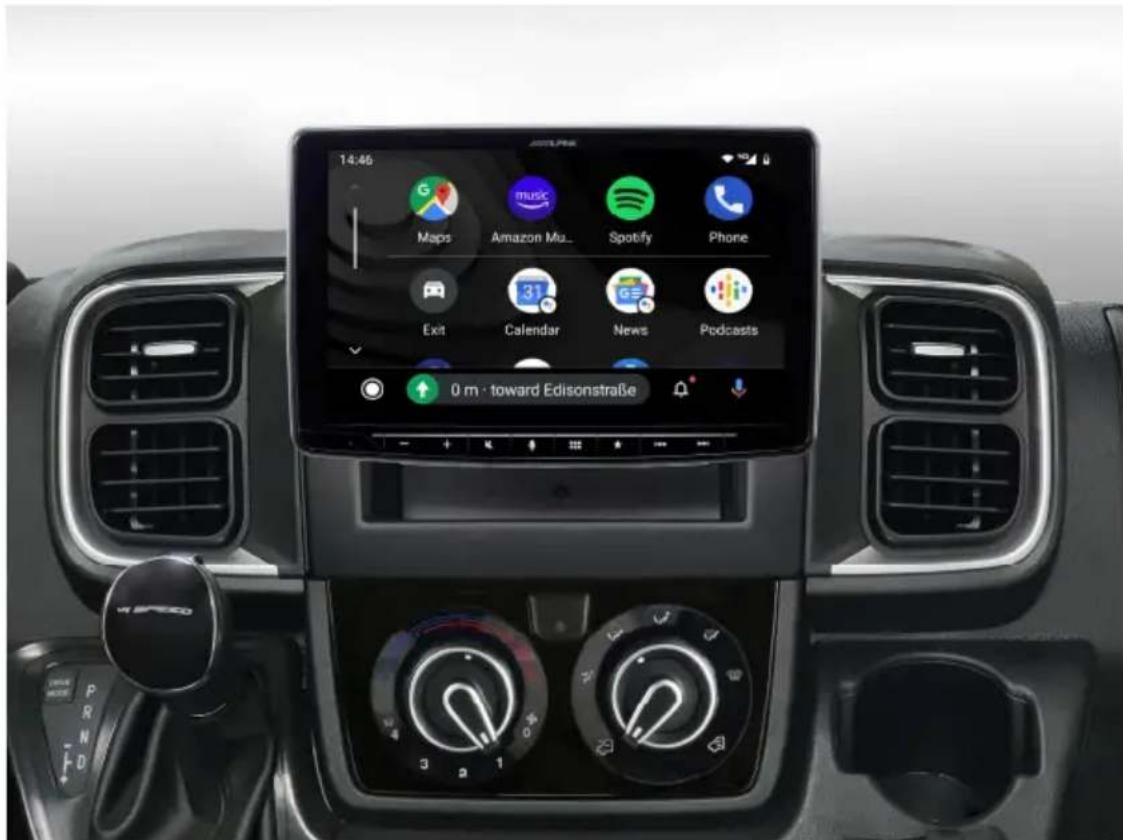
| Suitable Alpine Radios | INE-F904D(C), iLX-F903D, iLX-F905D, iLX-F115D |
| Kit Contents | SWRC CAN bus to UART interface, wiring harness with ISO connector, antenna DIN adapter, antenna FAKRA DAB+ adapter, camera adapter, plastic socket |
| Steering Wheel Functions | Seek Up/Down, Source, Volume Up/Down, Mute, Pick up incoming call, Hang up/Reject call, Voice Command |
| Interface Settings | Ignition Logic (Key/Door), Ignition Hold (0-30 min), Reverse Logic (Natural/Delayed), Reverse ON/OFF Hold (0-30s), Button Illumination (10 colors), Preflight Check, Button Configuration, Steering Wheel Side (Left/Right), Factory Reset |
| CAN Bus Connection | Yes, via instrument cluster (CAN High: Blue, CAN Low: White) |
| LIN Bus Connection | Yes, via grey connector on vehicle side |
| Additional Outputs | Speed output, Camera control/REMOTE out, Power antenna output, Reverse output |
| Antenna Adapters | ISO/DIN and FAKRA DAB+ |
| Camera Adapter | Included for rear/front camera input |
| Power Supply | From car's radio power connector (via wiring harness) |
| Installation | Professional installation required; connection to instrument cluster CAN bus and grey connector |
| Spare Part for Qi Charger | Alpine KWE-QI-DU8 required to retain wireless charging functionality |
| Safety | Installation must be performed by a qualified professional installer only |
Frequently Asked Questions - KIT-F9FI-DU8 ALPINE
User questions about KIT-F9FI-DU8 ALPINE
0 question about this device. Answer the ones you know or ask your own.
Ask a new question about this device
Download the instructions for your Uncategorized in PDF format for free! Find your manual KIT-F9FI-DU8 - ALPINE and take your electronic device back in hand. On this page are published all the documents necessary for the use of your device. KIT-F9FI-DU8 by ALPINE.
USER MANUAL KIT-F9FI-DU8 ALPINE
Steering wheel remote control interface for:
FIAT
Model: Ducato III Version 8 2021 → Ducato New Dash 2021 →
Kit content: SWRC CAN bus to UART interface with wiring harness and ISO connector; antenna DIN adapter; antenna FAKRA DAB ^+ adapter; camera adapter; plastic socket
Compatibility: Compatible with Ducato 8 Open-Dash version
Suitable for: INE-F904D(C) / iLX-F903D / iLX-F905D / iLX-F115D
All installation work must be performed by a qualified professional installer only. The manufacturer / dealer is not liable for any kind of incidental or indirect damages. 04/2022 ALL RIGHTS RESERVED. Technical changes possible. No liability for misprints.
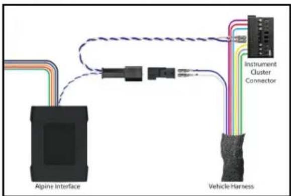
Content and wiring harness connections
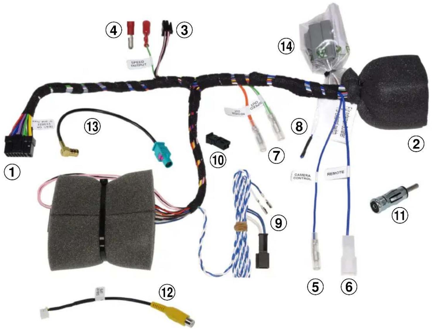
1 - to RADIO POWER connector
2 - to CAR connector
3 - to RADIO CONNECT2 I/F plug
4 - Green/White - SPEED output (connect to the Alpine radio)
5 - CAMERA control/REMOTE out
6 - POWER ANTENNA output
7 - to optional/extra SERVICES: Orange – REVERSE output Green/White – SPEED output
8 - to external switch (Blue cable)
9 - CAN BUS connection access cable
10 - CAN BUS housing for cables
11 - ISO/DIN antenna adapter
12 - CAMERA input adapter
13 - FAKRA antenna adapter for DAB ^+
14 - to CAR connector
ATTENTION!
Connect the connector n°15 to the GREY connector (vehicle side), do NOT connect it to the ORANGE connector (vehicle side)
ATTENTION!
For vehicle with FIAT wireless Qi charger, a separate adapter is needed. See page 6.
A. Connect the CAN bus cable to vehicle (point 10 / page 2).
natural_image
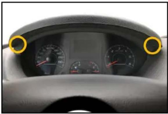
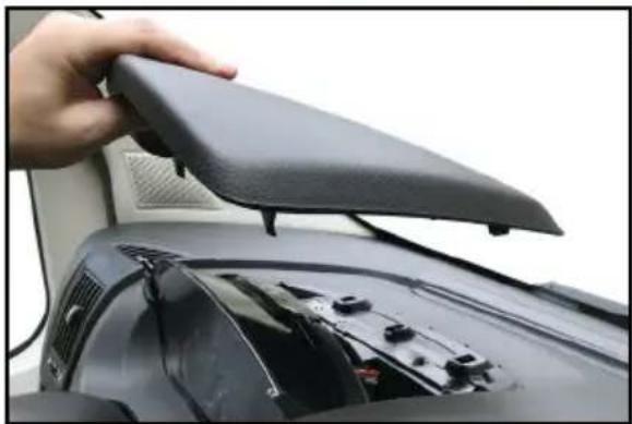
Interior view of a car dashboard with multiple gauges and a digital display (no visible text or symbols)- Remove the two screws of the instrument panel cover.
natural_image
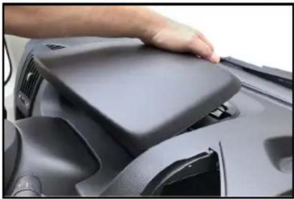
Close-up of a hand pressing down on a dark gray automotive seat cover (no visible text or symbols)- Lift the cover at the back first
natural_image
Close-up of a car's front bumper with a hand holding the lid (no visible text or symbols)- Now remove the cover completely from the instrument cluster.
- Establish a CAN bus connection to the instrument cluster. Laying the CAN cable from radio connector to the back side of instrument cluster.
natural_image
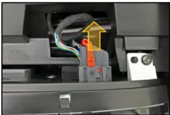
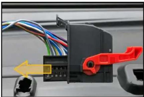
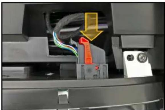
Close-up of a mechanical device interior with colored wires and a highlighted orange component (no visible text or symbols)- Remove the connector from the instrument panel.
A. Connect the CAN bus cable to vehicle (point 10 / page 2).
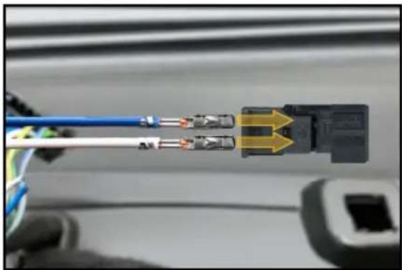
natural_image
Close-up of a black electrical connector with wires and a cable, showing internal wiring and a yellow directional arrow (no text or symbols)- Release the locking clips of the connector housing.
natural_image
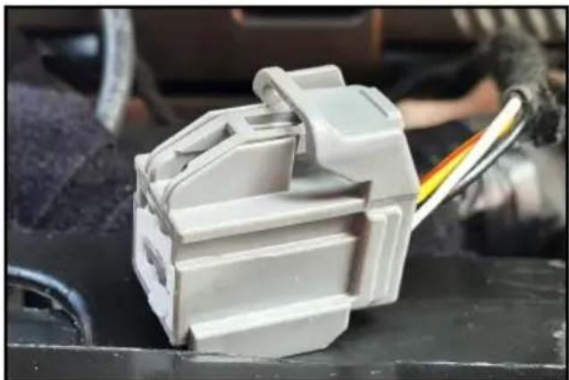
Close-up of a black plastic electrical connector with red plastic clip, showing wiring and port (no text or symbols visible)- Remove the connector from the housing.
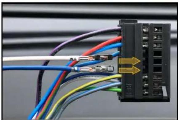
natural_image
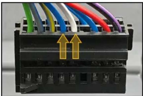
Close-up of a black electrical terminal block with multiple colored wires and two yellow arrows pointing upward (no text or symbols visible)- CAN cables colors: Blue = CAN High White = CAN Low
natural_image
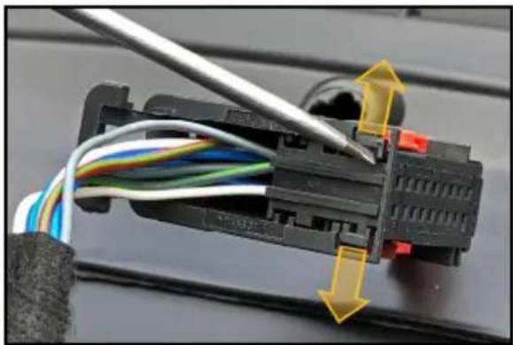
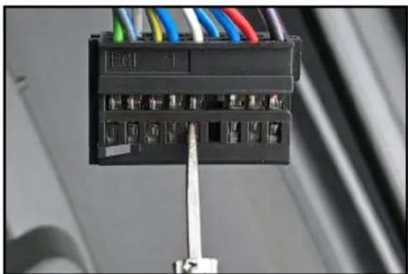
Close-up of a black electrical connector with multiple colored wires, mounted on a stand (no visible text or symbols)- Release the terminals of the CAN cables with the suggested release tool.
natural_image
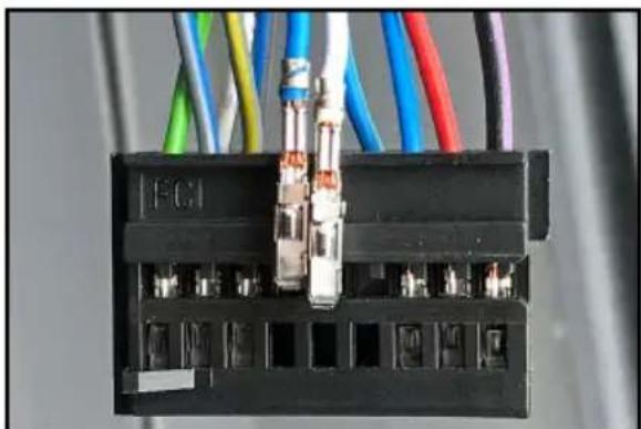
Close-up of an electrical connector with multiple colored wires and a labeled terminal (FCI), no readable text or symbols beyond the label.- Remove both cables.
A. Connect the CAN bus cable to vehicle (point 10 / page 2).
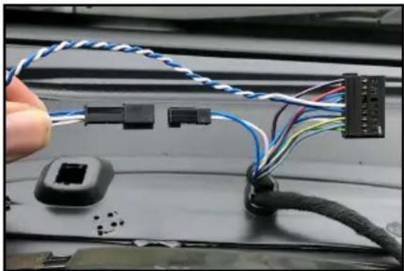
natural_image
Close-up of a cable connector with two wires and a connector, showing internal wiring (no text or symbols visible)- Insert both cables to the supplied 2-pin connector housing as shown.
natural_image
Close-up of a black network terminal block with multiple colored cables and connectors (no visible text or symbols)- Insert the terminals of the cables from the supplied T-Harness into the connector from the instrument cluster.
natural_image
Close-up of a hand holding a cable with various connector pins and wires, mounted on a laptop chassis (no visible text or symbols)- Connect both CAN plugs.
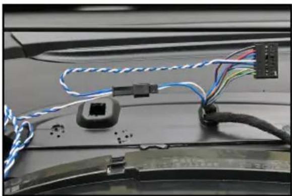
natural_image
Close-up of a car's front panel with colored wires and connectors (no visible text or symbols)- The CAN bus connection for the interface is now established.
natural_image
Close-up of a mechanical device interior with visible wiring and a yellow arrow indicating a component (no text or symbols)-
Assemble the connector housing and the cover from instrument cluster in reverse order.
-
Connect the harness as indicated on page 2 of this installation manual.
B. Connect the LIN bus cable to vehicle (point 15 / page 2).
natural_image
Close-up of a white plastic electrical connector with visible wiring and mounting base (no text or symbols)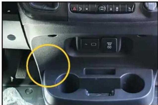
natural_image
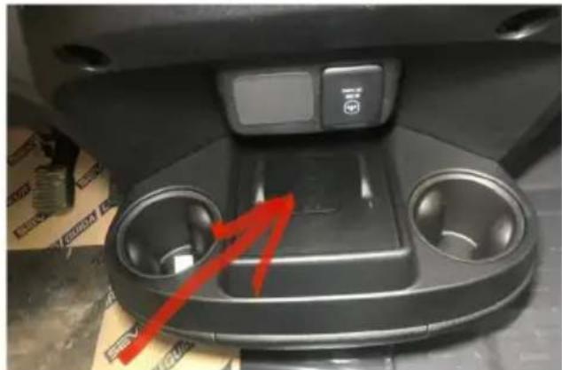
Interior view of a car dashboard with control panel and highlighted cable socket (no visible text or symbols)- The grey connector on vehicle side might be found directly inside the radio tunnel, or below the plastic cover for the FIAT wireless Qi charger. In this later case, the connector might be taped along the FIAT harness: just remove the tape and connect it to the supplied harness.
C. Additional accessories.
natural_image
Interior view of a car dashboard with two circular vented seats and a control panel (no visible text or symbols)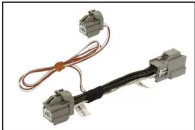
natural_image
Coiled electrical connector with two gray terminal blocks and a black cable (no text or symbols visible)- In case the vehicle is equipped with the FIAT wireless Qi charger, a separate spare part is required to retain it's functionality. Alpine part number: KWE-QI-DU8.
D. Steering wheel remote control functions.
The steering wheel remote control buttons perform the following functions (if supported by the radio / vehicle):
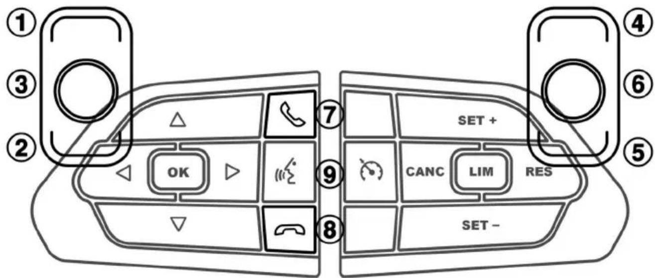
1 Seek +
6 M u t e
2 Seek -
7 Pick up incoming call
3 S o u r
& Hang up active call / Reject incoming call
4 Volume +
9 Voice Command
5 Volume -
E. Access the interface Information as shown in the pictures.
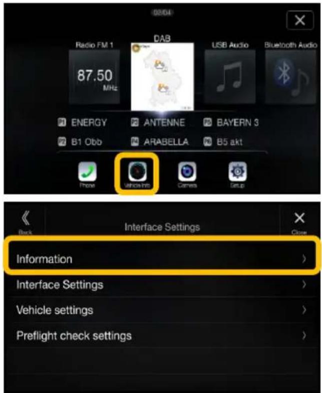
Select Information.


CAN Activity / LIN Activity
The CAN Activity must show "Yes". If "No" is shown, you need to confirm the connection of the CAN cables. The same applies to the "LIN Activity".
F. Access the Interface Settings as shown in the pictures.
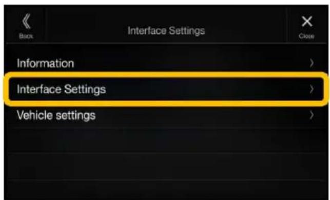
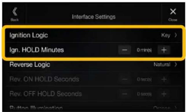
Ignition Logic (only if supported by vehicle)
- Switch between Key and Door
- Key = the radio switches on automatically when the key is turned in the ignition lock
- Door = the radio switches on automatically when the central locking (must be supported by the vehicle) of the door is opened (PRE-ignition)
Ignition HOLD Minutes
- Adjustable between 0 and 30 min(s)
- The radio "runs on" the set time (0 to 30 min(s)) when the ignition is switched off from the vehicle / radio
F. Access the Interface Settings as shown in the pictures.
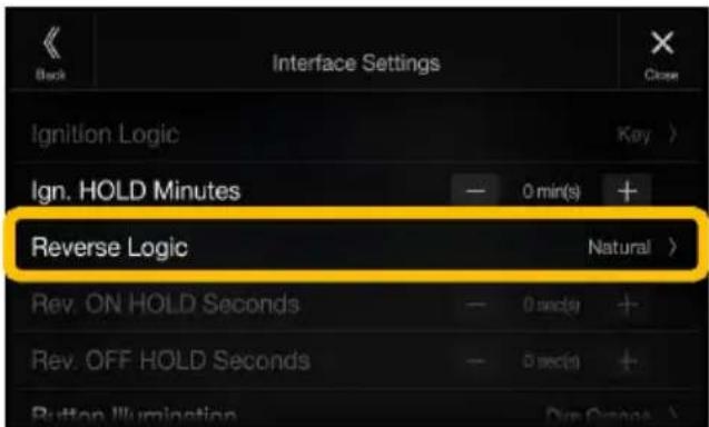
Reverse Logic
- Switch between Natural and Delayed
- Natural = Switches the reversing signal with activation / deactivation of the reverse gear immediately ON / OFF
- Delayed = Switches the reversing signal with activation / deactivation of the reverse gear with a delay ON / OFF
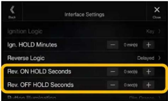
Reverse ON HOLD Seconds (0 to 30sec(s))
- When you are engaging the reverse gear, the interface will trigger the reverse to the radio after the time period (0 to 30sec(s)) specified in the menu.
Reverse OFF HOLD Seconds (0 to 30sec(s))
- When you are removing the reverse gear, the interface will remove the reverse to the radio after the time period (0 to 30sec(s)) specified in the menu. (The camera image of the rear-view camera is displayed accordingly longer.)
F. Access the Interface Settings as shown in the pictures.
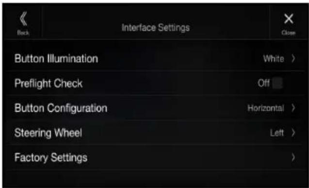
Button Illumination (only X903D-DU(2)/X903D-ID/X903D(C)-F)
- Switch the button illumination:
Orange, Dim Orange, Yellow, Dim Yellow, Red, Dim Red, Green, Dim Green, Blue, Dim Blue, White, Dim White
Preflight Check (On/Off)
- Selection of different notification options
- Driver receives notification before start if equipment is secured Button Configuration (only X903D-DU(2)/X903D-ID/X903D(C)-F)
- Configures the respective key assignment depending on the installed position of the keys (not used)
Steering Wheel (only X903D-DU(2)/X903D-ID/X903D(C)-F)
- Switchable between Left (default) and Right Factory Settings
- Resets all interface settings
G. Access the Pre-Flight Check Settings as shown in the pictures.
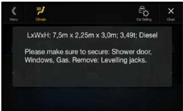
The Pre-Flight Check features shows the vehicle parameters and preselected warnings every time the engine is started.
*NOTE: The control of TV Tuner or DVD Player is no longer possible when ACC Control is activated.
G. Access the Pre-Flight Check Settings as shown in the pictures.
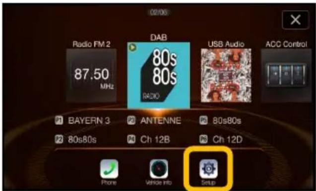
To enable the feature, select Menu → Setup.
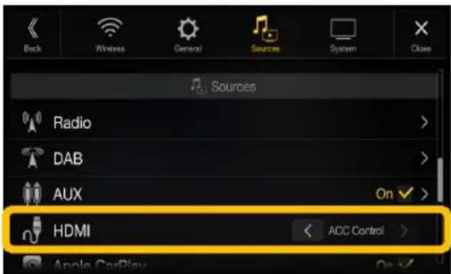
In the HDMI section select ACC Control*.
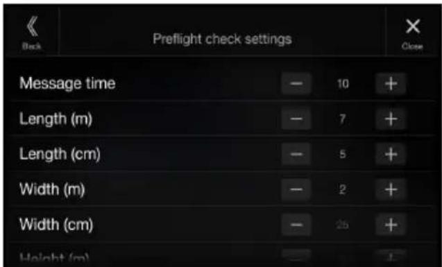
In the upper section you can configure how long the message will be shown and the vehicle parameters.

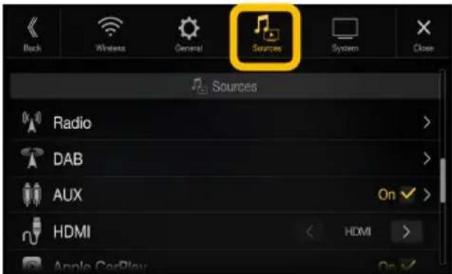
Select Sources from the upper icons.

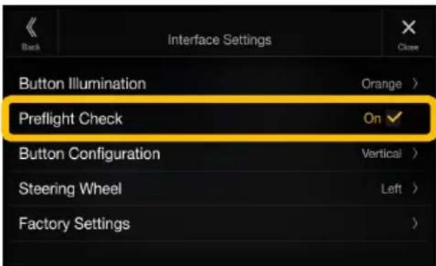
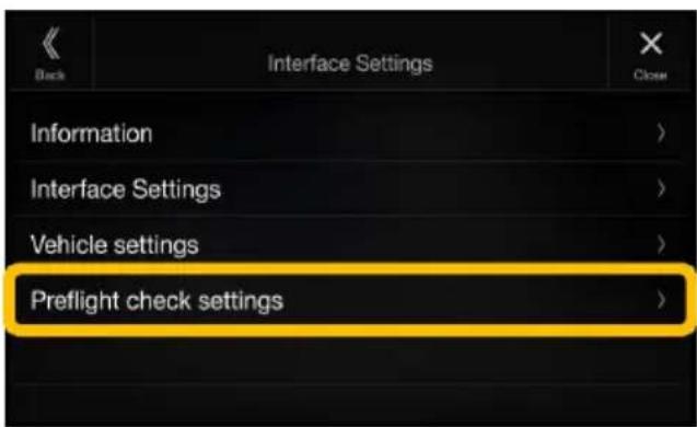
Now you can enable PreFlight Check in the Interface Settings. Go to the Interface Settings and set the preferred options under Preflight check settings.

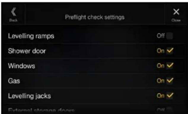
In the lower section, select items to be shown after the engine was started.
H. Connectivity Layout
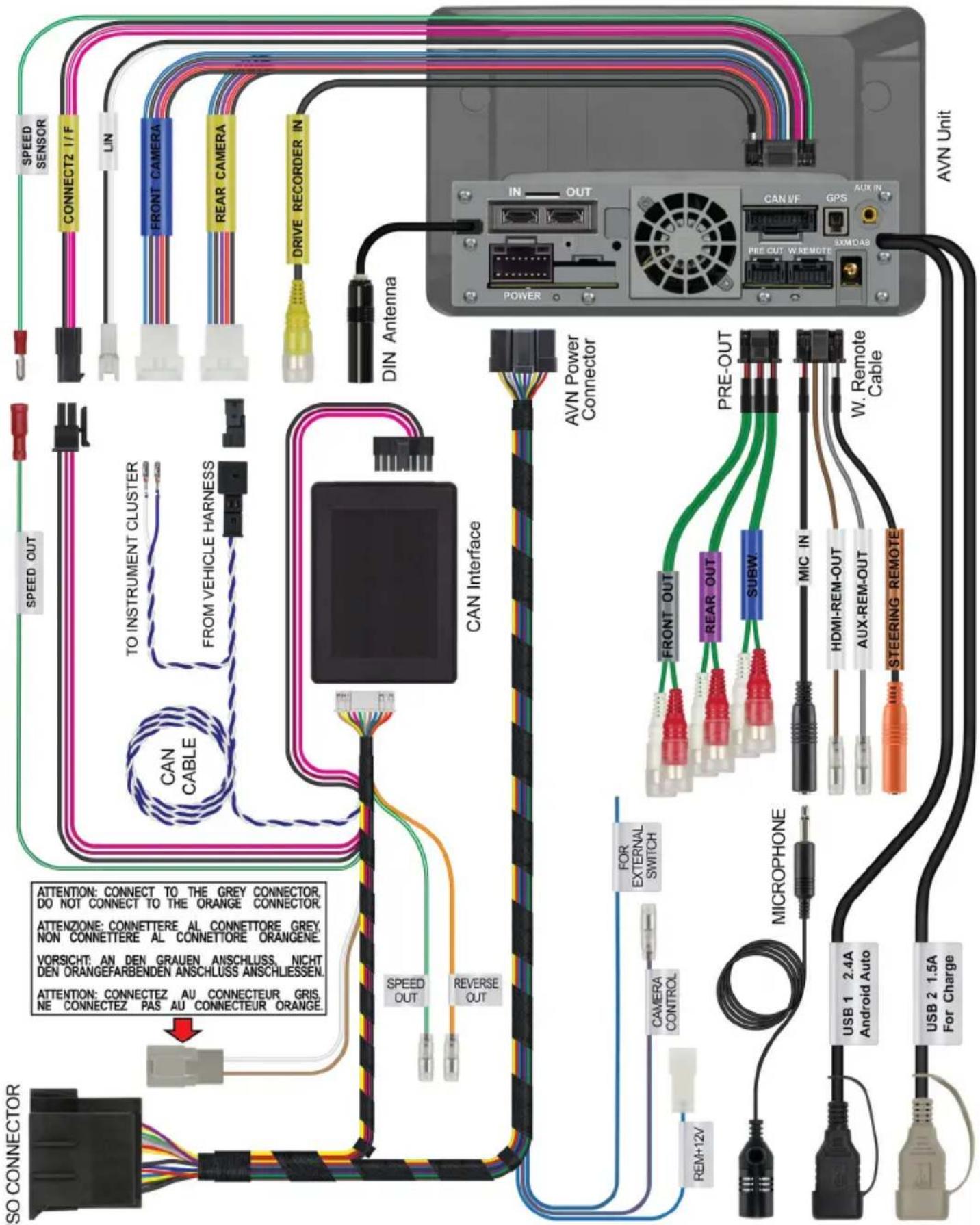
flowchart
graph TD
    A["ISO CONNECTOR"] --> B["CAN Interface"]
    B --> C["AVN Unit"]
    C --> D["PRE-OUT"]
    D --> E["MICROPHONE"]
    E --> F["USB 1 2.4A Android Auto"]
    E --> G["USB 2 1.5A For Charge"]
    B --> H["AVN Power Connector"]
    H --> I["DIN Antenna"]
    I --> J["SPEED SENSOR"]
    J --> K["CONNECT2 1/F"]
    K --> L["LIN"]
    L --> M["FRONT CAMERA"]
    M --> N["REAR CAMERA"]
    N --> O["DRIVE RECORDER IN"]
    O --> P["SPEED OUT"]
    P --> Q["SPEED OUT"]
    B --> R["FOR EXTERNAL SWITCH"]
    R --> S["CAMERA CONTROL"]
    S --> T["REMAIN OUT"]
    T --> U["FRONT OUT"]
    U --> V["REAR OUT"]
    V --> W["SUBW"]
    W --> X["SUBW"]
    X --> Y["FRONT OUT"]
    Y --> Z["REAR OUT"]
    Z --> AA["SUBW"]
    AA --> AB["PRE-OUT"]
    AB --> AC["W. Remote Cable"]
    AC --> AD["HDMI-REM-OUT"]
    AD --> AE["AUX-REM-OUT"]
    AE --> AF["STEERING REMOTE"]
    AF --> AG["USB 1 2.4A Android Auto"]

Brand : ALPINE
Model : KIT-F9FI-DU8
Category : Uncategorized