
MCD85 - CD Player MCINTOSH - Free user manual and instructions
Find the device manual for free MCD85 MCINTOSH in PDF.


| Product Type | SACD/CD Player |
| Disc Compatibility | CD, SACD, DVD (data) |
| Digital Inputs | 2x Coaxial (RCA), 2x Optical (TOSLINK), 1x USB Audio (Type B) |
| Analog Outputs | 1x Balanced XLR, 1x Unbalanced RCA |
| Fixed Output Level | 2.0Vrms Unbalanced, 4.0Vrms Balanced |
| Output Impedance | 100 ohms (Unbalanced and Balanced) |
| Signal-to-Noise Ratio | Better than 98dB (A-weighted) |
| Harmonic Distortion | 0.02% @ 1000Hz |
| Frequency Response | ±0.5dB from 20Hz to 20,000Hz |
| Supported File Formats | MP3, WMA, AAC, WAV, FLAC, ALAC, AIFF, DSD |
| Power Control (Trigger) | 12VDC, 25mA (1 Input, 1 Output) |
| Power Requirements | 100-240V AC, 50/60Hz, 35W (standby <0.5W) |
| Dimensions (W x H x D) | 12-5/32 x 7-3/4 x 16-1/4 inches (31.2 x 19.7 x 41.3 cm) |
| Weight | 20.5 lb (9.3 kg) net, 27.5 lb (12.5 kg) shipping |
| Remote Control | Infrared, uses 2x AAA batteries |
| Display | Vacuum Fluorescent Display (VFD) |
| Setup Menu | Access via left knob; includes Auto-Off, AutoMute, IR code, front IR, input setup, baud rate |
| IR Input | 1/8-inch jack for external IR receiver |
| RS232 Control | 1/8-inch jack; baud rate adjustable up to 115200 |
| Data Ports | 1 Input, 1 Output (3.5mm stereo mini plug) |
| USB Service Port | Rear panel, for service use only |
| Safety | Class 1 laser product; invisible laser radiation when open; user-serviceable parts inside? None |
| Ventilation | Minimum 6" above, 5/8" below, 2" sides, 18" depth behind front |
| Packaging | Includes foam pads and cardboard box; glass front panel requires careful packing |
Frequently Asked Questions - MCD85 MCINTOSH
User questions about MCD85 MCINTOSH
0 question about this device. Answer the ones you know or ask your own.
Ask a new question about this device
Download the instructions for your CD Player in PDF format for free! Find your manual MCD85 - MCINTOSH and take your electronic device back in hand. On this page are published all the documents necessary for the use of your device. MCD85 by MCINTOSH.
USER MANUAL MCD85 MCINTOSH
McIntosh Laboratory, Inc. 2 Chambers Street Binghamton, New York 13903-2699 Phone: 607-723-3512 www.mcintoshlabs.com
MCD85
SACD/CD Player
Owner's Manual
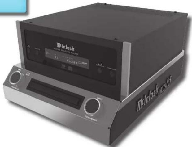
natural_image
Exterior view of a black Inlash Micro-DAV center console with control knobs and display screen (no visible text or symbols on the device body)
The lightning flash with arrowhead, within an equilateral triangle, is intended to alert the user to the presence of uninsulated "dangerous voltage" within the product's enclosure that may be of sufficient magnitude to constitute a risk of electric shock to persons.
WARNING - TO REDUCE RISK OF FIRE OR ELECTRICAL SHOCK, DO NOT EXPOSE THIS EQUIPMENT TO RAIN OR MOISTURE.

ATTENTION: RISQUE DE CHOC ELECTRIQUE - NE PAS OUVRIR
NO USER-SERVICEABLE PARTS INSIDE. REFER SERVICING TO QUALIFIED PERSONNEL.
The exclamation point within an equilateral triangle is intended to alert the user to the presence of important operating and maintenance (servicing) instructions in the literature accompanying the appliance.
To prevent the risk of electric shock, do not remove cover or back. No user-serviceable parts inside.
Additional Safety Information is supplied in a separate document "Important Additional Operation Information Guide"
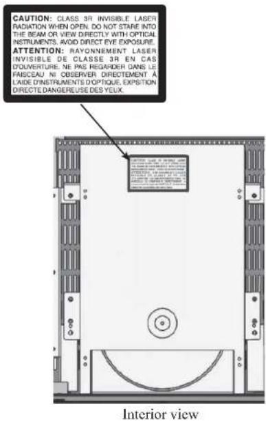
CAUTION:
Invisible Laser Radiation when open. DO NOT stare into the beam or view directly with optical instruments. Use of controls or adjustments or performance of procedures other than those specified in the Owners Manual may result in Hazardous Radiation Exposure.
ATTENTION:
This product incorporates an embedded CLASS 3R Laser (IEC60825-1).
LUOKAN 1 LASERLAITE KLASS 1 LASER APPARAT
VAROITUS!
The MCD85 SACD/CD Player marries McIntosh's long tradition of uncompromising quality with the latest cutting edge innovations to bring you an unsurpassed luxury sonic experience.
Thank you from all of us at McIntosh
With the MCD85 SACD/CD Player, you have invested in a precision instrument that will provide you with many years of enjoyment. Please take a few moments to familiarize yourself with the features and instructions to get the maximum performance from your equipment.
If you need further technical assistance, please contact your dealer who may be more familiar with your particular setup including other brands. You can also contact McIntosh with additional questions or in the unlikely event of needing service.
McIntosh Laboratory, Inc.
2 Chambers Street
Binghamton, New York 13903
Technical Assistance: (607) 723-3512
Customer Service: (607) 723-3515
Fax: (607) 724-0549
Email: support@mcintoshlabs.com
Website: mcintoshlabs.com
Make a Note
For future reference, you can jot down your serial number and purchase information here. We can identify your purchase from this information if the occasion should arise.
| Serial Number: | |
| Purchase Date: | |
| Dealer Name |
Safety First
Important Safety Information is supplied in a separate document "Important Additional Operation Information Guide"
Table of Contents
Thank you from all of us at McIntosh .... 3
Make a Note....3
Safety First....3
Where to put it .... 4
The Front Panel....5
The Left Knob 5
The Right Knob 5
Connections on the Back 6
The Inputs 6
The Outputs 6
Making Connections....6
Balanced/XLR Output....6
Unbalanced RCA/Phono Output....7
RS232....7
Wired IR Input....7
Power Control (Trigger) Output....7
Connection Diagram....8
Data Ports 9
Optical....9
Coax....9
Power On the MCD85....10
Setup Menu 10
IR Code.... 10
Data Setup.... 11
Play a Disc 11
Navigating CD-ROMs 11
Vacuum Fluorescent Display (VFD) 12
Remote Control Buttons 13
Changing the Remote Control's Battery ....14
Specifications 14
Resetting the Microprocessor 15
Packing the MCD85....15

Where to put it
The MCD85 can be placed upright on a table or shelf, standing on its four feet. It also can be custom installed in a piece of furniture or cabinet.
Always provide adequate ventilation for your MCD85. Cool operation ensures the longest possible operating life for any electronic instrument. Do not install the MCD85 directly above a heat generating
component such as a high-powered amplifier. If all the components are installed in a single cabinet, a quiet running ventilation fan can be a definite asset in maintaining all the system components at the coolest possible operating temperature.
A custom cabinet installation should provide the following minimum spacing dimensions for cool operation (Figure 02):
• 6 inches (15.3cm) above the top
- 5/8 inches (1.6cm) below the bottom
- 2 inches (5.1cm) on each side of the MCD85 so that airflow is not obstructed
• 18 inches (45.7cm) depth behind the front panel - 1-7/16 inch (3.7cm) in front of the mounting panel for knob clearance
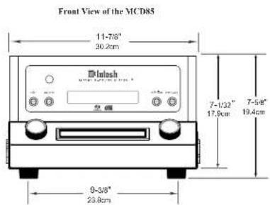
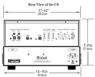

Figure 01- MCD85 Dimensions


Figure 02- Ventilation requirements

The Front Panel
The MCD85's glass and metal Front Panel provides two control knobs, four buttons and an informational display (VFD).
The Left Knob
The Left Knob, labeled BACK and NEXT on above the Knob and PUSH-SETUP below.
Push and release the Left Knob to enter the Setup Menu. Rotating the Left Knob will scroll through the Setup menu options.
When listening to the CD Player, rotating the Left
Knob Clockwise will advance to the next tracks. A counterclockwise turn will go to previous tracks.
The Right Knob
The Right Knob is labeled INPUT above the Knob and PUSH POWER below.
Push and release the Right Knob to Power On or Off. The Standby Indicator LED will glow red as long as AC Power is connected to the MCD85.
Rotating the Right Knob will scroll through the available Inputs. Stop turning when a desired Input is reached.
The Buttons
STOP, Disc LAYER, PLAY/PAUSE and OPEN/CLOSE are used to operate the CD PLAYER as seen in Figure 03.
The Disc LAYER button toggles between CD, STEREO (SACD), and MULTI (SACD). Push and release until you stop on the mode you want. Typically, either CD or Stereo. Stereo will play in SACD mode if supported on that disc. A regular CD will play as a regular CD in STEREO mode. Choosing MULTI will result in no sound because there is no multichannel processing. The MCD85 is a stereo SACD/CD player.

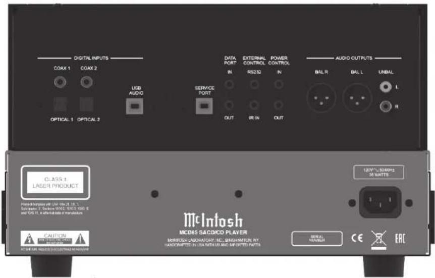
Figure 04- MCD85 Rear View
Connections on the Back
The Inputs
Two Digital Coax Inputs
Two Digital Optical Inputs
One USB Audio Input
One 1/8-inch jack for RS232 connector
One 1/8-inch jack for wired IR Input
One AC power connector
One USB upgrade service port
One 1/8-inch Data Input jack (IN)
One 1/8-inch Power Control (trigger) Input (IN)
The Outputs
One Pair unbalanced RCA Output
One pair balanced XLR audio Output
One 1/8-inch Data Output jack (OUT)
One 1/8-inch Power Control (trigger) Output (OUT)
Making Connections
Balanced/XLR Output
The Balanced Output (BAL L and BAL R) allows the MCD85 to be connected to a Balanced Input (typically a preamplifier). To use the XLR output, connect the BAL R to the right input of your preamplifier and BAL L to the preamplifier's left input.
Below is the Pin configuration for the XLR Balanced Input and Output Connectors on the MCD85.
PIN 1: Shield/Ground
PIN 2: + Signal
PIN 3: - Signal

Figure 05- XLR pin diagram
Unbalanced RCA/Phono Output
The Unbalanced Output (UNBAL L and R) allows the MCD85 to be connected to an input, typically of a preamplifier, using RCA/Phono cables. The top white jack is left (L) and the lower red jack is right (R).
RS232
The RS232 jack is used to connect the MCD85 to automation controller devices with RS232 connectors. To utilize this feature, you will need an appropriate RS232 Data Cable. The RS232 Data Cable should be an 1/8 inch (3.5mm) stereo mini phone plug to a subminiature DB9 connector.

RS232 DB9 Connector Pin Layout
- N/C (no connection) 6. N/C
- Data In (RXD) 7. N/C
- Data Out (TXD) 8. N/C
- N/C 9. N/C
- Gnd
Typical RS232 settings are:
• 8 data bits, no parity and one stop bit
- Baud rate fixed at 115,200 bits per second
The baud rate can be changed in the Setup. See "Baud Rate Setup" on page 11.
Wired IR Input
The IR Input allows an external IR receiver to be attached to the MCD85. The Input is labeled IR IN. By attaching an IR receiver using a 3.5mm cable (see Figure 08), the MCD85's Remote Control can be used in another location without a line-of-sight to the MCD85's front IR sensor.

Figure 08 IR 3.5mm connector
If using an external IR receiver for the MAIN ZONE in the same room as the MCD85, you may wish to disable the front IR sensor. This will avoid potential timing issues of receiving the Remote Control's commands from two different Inputs. The front IR can be turned on/off by doing the following:
- Press and Hold the Left Knob for two seconds
- Turn the Left Knob to the menu choice "SETUP: Front IR"
- Turn the Right Knob clockwise for Enabled (on) or counterclockwise (off)
- Press and release the Left Knob to exit the Setup menu
AC Power
This connection is essential. Plug the female end of the supplied AC Power Cord into the AC connector (standard 15 ampere IEC) located in the rear right corner of the MCD85. Plug the male end of the AC Power Cord into a grounded and functioning AC outlet.
Power Control (Trigger) Output
The MCD85 has two Power Control jacks or Triggers. One is an input (IN) and the other is an output (OUT).
Power Control enables power on/off signals to go to connected components so that other components can automatically powered on (or off).
The controlling unit should be connected to the IN jack. The MCD85 and units connected to the OUT jack will follow the power status of the controlling unit.
Connect components to the Triggers using a 3.5mm stereo mini plug. See Figure 09. The Triggers work by sending on/off signals in the form of +12 volt/0 volt to connected McIntosh components.

Figure 09 Power control (trigger) mini plug
continued on page 9

Connection Diagram
Here are some common connections for the MCD85:

Data Ports
The IN DATA PORT allows a connected McIntosh component to send basic converted IR commands to control the MCD85 even from another room. The OUT DATA PORT will send the converted IR commands to another attached McIntosh component.
To connect a McIntosh unit to a Data Port, use a 3.5mm stereo mini phone plug cable, Figure 10.
The USB AUDIO input of the MCD85 provides the capability to receive music/sound in a digital format from a connected computer.
Software Requirements
Apple ^® Macintosh ^® computers require OS-10.6.8 or later. Apple computers require no additional driver install to communicate with the MCD85.
For Windows-based computers (PC), Windows 7 (SP1) or later is required. The correct McIntosh USB Audio driver must be installed for the PC to communicate with the MCD85.
To install the McIntosh USB Driver for Windows-based computers:
Download the latest driver from the McIntosh website: https://www.mcintoshlabs.com/products/integrated-amplifiers/MCD85
The driver can be found in the Downloads section of the webpage under Software Updates. Choose the DA1 Digital Audio Module: McIntosh USB Audio Windows Driver.
- Unzip the McIntosh_UsbAudio file
- Run the File
- Choose "Yes" to allow changes to your computer (See Figure 11)
- Follow software prompts selecting "Next" or "Install" as needed
- Click "Finish" when drvier is installed
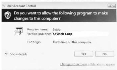
Figure 11 Installing USB Driver Software
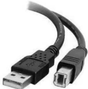
Next, connect the Computer to the MCD85 using a USB 2.0 Cable Type A to Type B (see Figure 12). Windows should detect the new device (if you installed the driver software as directed above) and
natural_image
Close-up of a USB and DNA port connector (no text or symbols visible)Figure 12- USB cable
install the driver as indicated by a message in the lower part of your monitor.
You can use the Windows Control Panel to select the new audio device which will appear as "McIntosh HD-HS USB Audio". You may also select this driver in many third-party applications such as JRiver Media Center.
The MCD85's display will show the sampling rate or bit rate for the USB input.
USB Service Port
The USB SERVICE PORT on the rear of the MCD85 is for McIntosh service use only. Use the USB AUDIO port for audio input.
Optical
The two Optical Inputs allow digital sources to be connected to the MCD85 using TOSLINK cables also known as "optical audio cables." The Optical Inputs can handle high resolution digital audio up to 192kHz/24-bit. The MCD85 DAC will process standard format SPDIF PCM signals. Unsupported formats can result in strange and/or unpleasant sounds.
Coax
The two Digital Coax (Coaxial) Inputs allow digital sources to be connected to the MCD85 using Digital Audio RCA Coaxial Cables. The Coax Inputs can handle high resolution digital audio up to 192kHz/24-bit. The MCD85 DAC will process standard format SPDIF PCM signals. Remember, unsupported formats can result in strange and/or unpleasant sounds.

Power On the MCD85
To power on the MCD85, press and release the Right Knob. To power the MCD85 off, do this again.
Setup Menu
To enter the Setup Menu, push and release the Left Knob. Turning the Left Knob will scroll through the available options.
| Setting Options | |
| MCD85 Displays current firmware version | |
| S/N AJGxxxx Displays the serial number of the MCD85 | |
| DA FW Vx.x Displays the current firmware for the digital adapter | |
| Auto-Off ON (default) / OFF | |
| AutoMute ON (default) / OFF | |
| IR Code Norm (default) / Alt | |
| Front IR ON (default) / OFF | |
| Power IR ON (default) / OFF | |
| IR Input ON (default) / OFF | |
| DATA All (default), | COAX 1, COAX 2, OPT 1, OPT 2 |
| Inputs (HOLD) Hold Left Knob to enter submenu | Submenu Choices: CD PLAYER, COAX 1, COAX 2, OPT 1, OPT 2, USB Options for each: ON (default) / OFF |
| BAUD 115200 (default), | 9600, 19200, 38400, 57600 |
Firmware Version
Firmware is internal software that controls the MCD85's functionality.
The version of the main firmware of the MCD85 can be viewed by entering the Setup Menu. Enter this by pressing and releasing the Left Knob. The first setting is called MCD85. The number to the right is the version number. For example, if the VFD displays "MCD85 V1.01", then the main firmware is version 1.01.
There is also firmware for controlling the digital audio hardware. To see the Digital Audio (DA) firmware version, enter the Setup Menu. Rotate the Left Knob until you see "DA FW". The number following the V to the right is the Digital Audio firmware version.
Firmware upgrades when available can be installed by qualified technicians.
Serial Number
The MCD85's unique serial number can be viewed by entering the Setup Menu and rotating the Left Knob until you see "S/N:". The number (and letters) to the Right are the unit's serial number. This number can also be found on the rear of the unit.
Auto-Off
Auto-Off can be toggled On (default) or Off. Enter the Setup Menu. Select On or Off by rotating the Right Knob.
When the Auto-Off feature is enabled, the MCD85 will power off when no audio input or user interaction has been detected for approximately 30 minutes.
AutoMute
The Automute Feature helps to ensure noise free playback of streaming music via the USB Input. With AutoMute enabled, the MCD85 will employ a brief mute as the Digital Audio Signal format changes (PCM, DSD, etc.). Occasionally, because of the particular way a recording was produced, it may be desirable to switch Off the Automute Feature. This will eliminate the brief gap between different formats.
To toggle AutoMute On or Off, enter the Setup Menu. Select On or Off by rotating the Right Knob.
IR Code
The IR Code setting allows you to select an alternative set of remote control codes to use for the remote control of the MCD85. The default is to use the Normal control codes which will be perfectly fine for the vast majority of situations. If you have another unit being controlled with the same control codes, conflicts can arise. If this is the case, change IR Code setting to "Alt". The remote control for the MCD85 must also be set to use the alternate codes. To set the MCD85's remote control to use alternate (Alt) codes, press and hold the SELECT button and press the "2" button. Hold until the two LEDs to the right of the SHIFT button flash twice.
To set the MCD85's remote control to use normal codes, press and hold the SELECT button and press the "1" button. Hold until the two LEDs to the right of the SHIFT button flash twice.
Front IR
Front Panel Sensor, which receives the signals from the Remote Control, can be switched off to prevent interference when an external IR Sensor
is connected. To de-activate the Front IR, enter the Setup Menu. Select On or Off by rotating the Right Knob.
Power IR and IR Input
The MCD85 can be controlled by another McIntosh unit's remote control using the DATA IN PORT. This is convenient for using commands on the other remote such as PLAY or NEXT, but it is possible that you may not want Power commands or Input commands sent by the connected unit to control the MCD85.
If you wish to disable Power Commands coming from the DATA PORT or from a connected external IR sensor connected the IR IN, enter the Setup Menu. Select On or Off by rotating the Right Knob. If you wish to disable Input Commands coming from the DATA PORT or from a connected external IR sensor connected the IR IN, enter the Setup Menu. Select On or Off by rotating the Right Knob.
Data Setup
Data Port connections allow the Remote Control commands sent to the MCD85 to be sent to components attached via the Data Ports. Data Setup defines when to send that data based on the selected Input. The default is "All" which will send data to a connected component whenever data is received. The options for when to send data are:
- All (Default)
- Coax 1
- Coax 2
- Opt 1
- Opt 2
To select when Data will be send a component connected to the DATA OUT PORT, enter the Setup Menu. Rotate the Right Knob to select one of the
available options.
Input Setup
You have the ability to control which inputs appear on the display when you rotate the Input (Right) Knob. If you wish to remove an unused input or restore a previously removed input:
- Push and release the Left Knob to enter Setup
- Rotate the Left Knob until the VFD displays "Inputs (Hold)"
- Press and Hold the Left Knob for two seconds. "CD PLAYER" will appear in the VFD
- Rotate the Left Knob to select the input you wish to display or hide
- Rotate the Right Knob to select On or Off
- Press and release the Left Knob twice to exit the Setup Menu
Baud Rate Setup
The MCD85 can be controlled remotely via the RS232 Jack. The settings for serial communications are:
8 bit, No parity and 1 stop bit The speed can be adjusted from the Setup Menu. To adjust the BAUD rate, enter the Setup Menu. Rotate the Left Knob until you reach “BAUD: ...” Rotate the Right Knob to select from the following options:
9600, 19200, 38400, 57600, and 115200 (default).
FACTORY RESET
Use the FACTORY RESET option if you wish to return all settings to factory defaults. All previous setup changes will be lost.
To Factory reset the MCD85, enter the Setup Menu.
Rotate the Left Knob until “FACTORY RESET” appears on the display. Hold the Left Knob down until “In Progress” appears on the screen. When the Factory reset is complete, the MCD85 will power off.
Play a Disc
- Rotate the Right Knob (INPUT) until CD PLAYER appears on the Display
- Press and release the OPEN/CLOSE button to open the tray
- Place the disc, label side up, on the tray
- Press and release the OPEN/CLOSE button to close the tray
- “Reading” will appear on the Display followed by Disc information
- You may rotate the Left Knob (BACK NEXT) to pick a particular track
- Press and release the PLAY/PAUSE button to Play; press again to Pause
Additional commands are available on the Remote Control. See "Remote Control Buttons" on page 13.
The Program Playback feature allows the playback of selected tracks in a chosen order. To use this feature, Press the SHIFT button on the Remote Control and then press the RANDOM button twice. Use the numeric buttons to enter the desired tracks. Press the Play ▶ button to begin playing the programmed tracks.
Navigating CD-ROMs
The Remote Control buttons 2, 4, 6 and 8 can be used for navigating up, down, left, right through tracks/folders on a CD-ROM. The 5 button can be used to Enter the folder or Play the track shown on the Display.
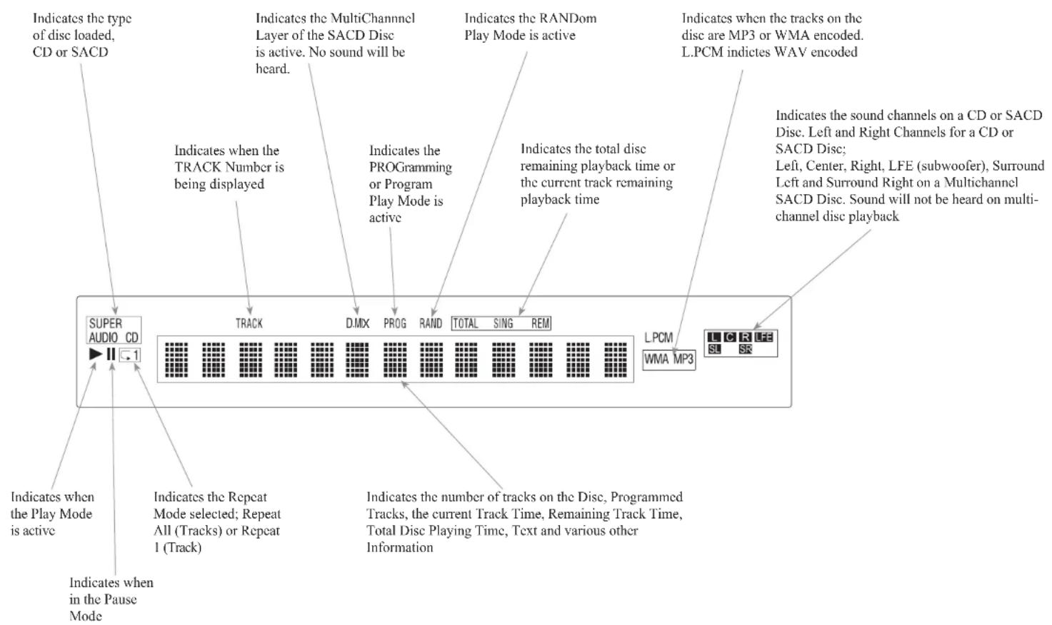
Vacuum Fluorescent Display (VFD)
Remote Control Buttons
SHIFT push-button with LED Indicators used to select a push-button function with white or gold color nomenclature
Use to CLEAR the last programmed track
Access the TEXT Display Mode when playing a SACD Disc containing the information
Use to select various disc information, including TIME, on the Front Panel DISPLAY. It is also used to cancel the text display mode on a SACD Disc
Use to select the SACD or CD Tracks from a hybrid disc for playback
Press to play the Previous Selection. Also used to select one of various REPEAT modes
Press once to PLAY, a second time to PAUSE and a third time to RESUME playback. Also used to activate RANDOM playback of the tracks on a SACD or CD disc
Press to FAST-REVERSE thru the current selection

Momentarily press to Power ON or OFF
Use to select disc tracks or any numbered operation
Use to direct access tracks 10 and above
Selects the All MODE or the Folder MODE for navigating and selection of music on a CD-R or DVD =R and Flash Drive
LEVEL Control adjusts the volume level for the Rear Panel Variable Audio Output Connectors and the Front Panel Headphone Jack
Press to play the next Selection
Press to FAST-FORWARD thru the current selection
Select Disc, USB Mode or Coax/Optical Digital Inputs
Press to STOP disc playback
Note: The Remote Control Push-buttons not identified are for use with other McIntosh Products

Changing the Remote Control's Battery
Someday, the two AAA battery in the Remote Control will need to be replaced. To replace the two AAA batteries:
- Locate the battery door. Looking at the back of the remote, the battery door is in the lower part
- Slide battery door towards the bottom of the Remote Control. The battery door will slide open 1/4 inch (0.63cm)
- Lift the door up to reveal the batteries
- Remove the old batteries
- Insert two new AAA batteries noting the polarity which is printed on the bottom of the battery compartment. The spring will connect with the negative (-) part of the battery
- Place the door over the batteries leaving a 1/4 inch gap
- Slide the door up towards the top of the remote to secure
Specifications
Disc Media
CD, SACD, DVD (data)
Fixed Output level
2.0Vrms Unbalanced
4.0Vrms Balanced
Output Impedance
100 ohms Unbalanced and Balanced
Signal to Noise Ratio
Better than 98dB (A-weighted)
Harmonic Distortion
0.02% @ 1000Hz
Frequency Response
±0.5dB from 20Hz-20,000Hz
playable Disc Media Files
| Format Up To F | frequency/Bit | Bit Rate |
| MP3 (.mp3) 48K | Hz up to 320kbps | |
| WMA (.wma) 48K | Hz up to 320kbps | |
| AAC (.aac/mp4) | 48KHz up to 320kbps | |
| WAV (w a v) 192 | KHz/24 Bit* uncompressed | |
| JLAC (.flac) 192 | KHz/24 Bit* uncompressed | |
| ALAC (.m4a) | 96KHz/24 Bit* | uncompressed |
| AIFF (.aif/aiff) | 192KHz/24 Bit* | uncompressed |
| DSD (.diff/dsf) D | SD128 (5.6MHz) uncompressed |
*up to 48KHz with CD-R/+RW
Power Control and Trigger Output
12VDC, 25mA
Power Requirements
Field AC Voltage conversion of the MCD85 is not possible. The MCD85 is factory configured for one of the following AC Voltages:
100 Volts, 50/60Hz at 35 watts
110 Volts, 50/60Hz at 35 watts
120 Volts, 50/60Hz at 35 watts
220 Volts, 50/60Hz at 35 watts
230 Volts, 50/60Hz at 35 watts
240 Volts, 50/60Hz at 35 watts
Standby, less than 0.5 watt
Note: Refer to the rear panel of the MCD85 for the correct voltage.
Overall Dimensions
Width is 12-5/32 inches (31.2 cm)
Height is 7-3/4 inches (19.7cm) including feet
Depth is 16-1/4 inches (41.3cm) including the Front Panel, Knobs and Cables
Weight
20.5 pounds (9.3Kg) net, 27.5 pounds (12.5Kg) in shipping carton
Shipping Carton Dimensions
Width is 20-3/8 inches (51.8cm)
Height is 13-1/4 inches (33.7cm)
Depth is 16-1/4 inches (41.3cm)
Resetting the Microprocessor
In the unlikely even the MCD85 stops functioning properly and the Factory Reset procedure (see "FACTORY RESET" on page 11) does not solve the issue, you can try the following procedure to reset the secondary (transport) microprocessor:
• Power off the MCD85
- Remove the AC power cord from the rear of the MCD85
- Wait a few seconds for the standby LED to turn off
- Push and Hold the Left Knob in while pressing and holding the STOP button
- Plug the AC power cord into the rear of the MCD85
- When "INITIALIZED" appears on the Display, release the Left Knob and STOP button
The MCD85 should be reset in a few more seconds.
Packing the MCD85
When shipping the MCD85, it is highly recommended that the unit be packed as it was originally shipped to avoid damage. Failure to properly pack the unit will likely result in damage. (The front panel is made of glass!) If you need any of the packing material, you can contact McIntosh Customer Service. Use only packing material that is in good condition and replace any material that has seen better days.
It is very important that the four plastic feet are properly placed in the holes of the Foam Bottom Pad. This will ensure the proper equipment location for shipping. Failure to do this will result in shipping damage.
Quantity Part Number Description
1 034661 Shipping Carton
1 034654 Foam Pad Bottom
1 034658 Foam Top Cover
1 034656 Foam Ring
1 034657 Foam Upper Ring
1 034655 Foam Top
1 034662 Sheet Slit Scored

Figure 13- Re-packing diagram

The continuous improvement of its products is the policy of McIntosh Laboratory Incorporated who reserve the right to improve design without notice.
Printed in the U.S.A.
McIntosh Part No. 24110300


- MCD85
- WARNING - TO REDUCE RISK OF FIRE OR ELECTRICAL SHOCK, DO NOT EXPOSE THIS EQUIPMENT TO RAIN OR MOISTURE.
- NO USER-SERVICEABLE PARTS INSIDE. REFER SERVICING TO QUALIFIED PERSONNEL.
- To prevent the risk of electric shock, do not remove cover or back. No user-serviceable parts inside.
- CAUTION:
- ATTENTION:
- LUOKAN 1 LASERLAITE KLASS 1 LASER APPARAT
- VAROITUS!
- Thank you from all of us at McIntosh
- Make a Note
- Safety First
- Table of Contents
- Where to put it
- The Front Panel
- The Left Knob
- The Right Knob
- The Buttons
- Connections on the Back
- The Inputs
- The Outputs
- Making Connections
- Balanced/XLR Output
- Unbalanced RCA/Phono Output
- RS232
- Wired IR Input
- AC Power
- Power Control (Trigger) Output
- Connection Diagram
- Data Ports
- Software Requirements
- USB Service Port
- Optical
- Coax
- Power On the MCD85
- Setup Menu
- Firmware Version
- Serial Number
- Auto-Off
- AutoMute
- IR Code
- Front IR
- Power IR and IR Input
- Data Setup
- Input Setup
- Baud Rate Setup
- FACTORY RESET
- Play a Disc
- Navigating CD-ROMs
- Remote Control Buttons
- Changing the Remote Control's Battery
- Specifications
- Disc Media
- Fixed Output level
- Output Impedance
- Signal to Noise Ratio
- Harmonic Distortion
- Frequency Response
- Power Control and Trigger Output
- Power Requirements
- Overall Dimensions
- Weight
- Shipping Carton Dimensions
- Resetting the Microprocessor
- Packing the MCD85
Brand : MCINTOSH
Model : MCD85
Category : CD Player