
Aruba Unified AP-345 - Access Point HP - Free user manual and instructions
Find the device manual for free Aruba Unified AP-345 HP in PDF.

| Product Type | Wireless Access Point |
| Model | Aruba Unified AP-345 |
| Brand | HP (Aruba) |
| Wi-Fi Standards | 802.11ac Wave 2 (dual-band 2.4 GHz and 5 GHz) |
| MIMO | 4x4:4 (4 spatial streams) with MU-MIMO |
| Maximum Data Rate | Up to 1733 Mbps (5 GHz) + 800 Mbps (2.4 GHz) |
| Dimensions (H x W x D) | 200 mm x 200 mm x 42 mm (7.9 x 7.9 x 1.7 in) |
| Weight | 1.2 kg (2.65 lbs) |
| Power Supply | 802.3at PoE+ (Power over Ethernet) or 12V DC |
| Power Consumption | Maximum 20W |
| Ethernet Ports | 1x 10/100/1000 Base-T (RJ-45) |
| Mounting | Ceiling or wall mount (brackets included) |
| Antenna Type | Internal omnidirectional (4 per band) |
| Security Features | WPA2, WPA3, 802.1X, rogue AP detection |
| Management | Aruba Central, Aruba Instant, or controller-based |
| Operating Temperature | 0°C to 40°C (32°F to 104°F) |
| Storage Temperature | -40°C to 70°C (-40°F to 158°F) |
| Humidity | 5% to 93% non-condensing |
| Certifications | FCC, CE, RoHS |
| Included Accessories | Mounting bracket, screws, power adapter (optional) |
| Cleaning Instructions | Wipe with a dry, soft cloth. Do not use liquids or sprays. |
| Reparability | No user-serviceable parts. Contact support for repairs. |
Frequently Asked Questions - Aruba Unified AP-345 HP
User questions about Aruba Unified AP-345 HP
0 question about this device. Answer the ones you know or ask your own.
Ask a new question about this device
Download the instructions for your Access Point in PDF format for free! Find your manual Aruba Unified AP-345 - HP and take your electronic device back in hand. On this page are published all the documents necessary for the use of your device. Aruba Unified AP-345 by HP.
USER MANUAL Aruba Unified AP-345 HP
Aruba 340 Series Campus Access Point
Installation Guide
Aruba 340 Series Campus Access Point 340 Series (AP-344 and AP-345) are high-performance dual-radio wireless devices. These access points (AP) provide secure wireless connectivity for 2.4GHz 802.11 b/g/n and 5GHz 802.11a/n/ac Wi-Fi networks. The optional dual-5GHz radio mode allows both radios to operate in the 5GHz radio mode simultaneously, doubling the 5GHz capacity of the access point. The 340 Series can be deployed in either a controller-based (ArubaOS) or controllerless (InstantOS) network environment. Two wired Ethernet ports located on the back of this access point are available to connect the access point to the wired infrastructure and to deliver power the device.
This access point can be attached to a standard flat 9/16" or 15/16" suspended ceiling rail using the mount adapters provided. Other mounting options are supported by additional mount kits (sold separately). Aruba 340 Series Campus Access Point 340 Series provide the following capabilities:
- Wireless access
- Wireless mesh
• Air Monitor (AM)*
• Spectrum Monitor (SM)*
• Support for selected USB peripherals
• Integrated Bluetooth Low Energy (BLE) radio
* Air Monitor and Spectrum Monitor features are not supported while this device operates in dual-5GHz mode.
Package Contents
The following materials are included with this product:
• Aruba 340 Series Campus Access Point
- 9/16" and 15/16" ceiling rail mount adapters

Inform your supplier if there are any incorrect, missing, or damaged parts. If possible, retain the carton, including the original packing materials. Use these materials to repack and return the unit to the supplier if needed.
Hardware Overview
The following sections describe the hardware components of the 340 Series access point.
Figure 1 Aruba AP-345 (front view)
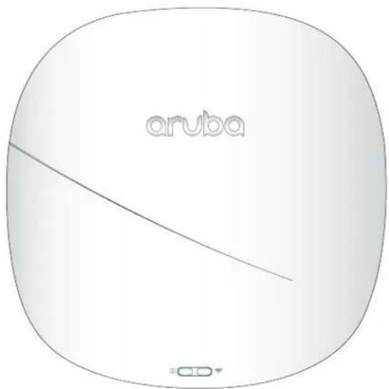
LED
The LED displays located on the front panel of the access point indicate the following functions:
System Status ⓘ
The System Status LED indicates the operating condition of the access point, See Table 1.
Table 1 System Status LED
| Color/State Meaning | |
| Off Device is powered off | |
| Green - blinking1 | Device is booting; not ready |
| Green - solid Device is ready; fully functional, no network restrictions | |
| Green - flashing2 | Device is ready; either uplink is operating at sub-optimal speed (<1Gbps) |
| Amber - solid Device is ready; operating in Power Save mode due to one of the following conditions: · powered by an 802.3af POE source · Intelligent Power Monitoring (IPM) restrictions applied No network restrictions | |
| Amber - flashing | Device is ready; operating in Power Save mode due to one of the following conditions: · powered by an 802.3af POE source · Intelligent Power Monitoring (IPM) restrictions applied Either uplink is negotiating at suboptimal speed (<1Gbps) |
| Red - solid Error condition - immediate action required | |
1 Blinking: one second on/one second off
2 Flashing: mostly on, shortly off every two seconds
Radio Status

The Radio Status LED indicates the operating mode of the access point's radios. See Table 2.
Table 2 Radio Status LED
| Color/State Meaning | |
| Off Meets one of the following conditions:device is powered offboth radios are disabled | |
| Green - solid Both radios operating in access mode | |
| Green - blinking One radio operating in access mode; one radio disabled | |
| Amber - solid Both radios operating in monitor mode | |
| Amber - blinking One radio operating in monitor mode; one radio disabled | |
| Alternating3 | One radio operating in access mode; one radio in monitor mode |
| Blue - Solid | Both radios operating in dual 5GHz mode |
3 Alternating: light cycles alternate between green/amber; one second on/one second off.
LED Display Settings
The LEDs have three operating modes that can be selected in the system management software:
• Default mode: Refer to Table 1 and Table 2
• Off mode: LEDs are off
- Blink mode: LEDs blink green
To cycle through the modes, press the push button located on the back-right corner of the device using a small, narrow object, such as a paperclip.

Holding the button for 10 seconds or longer will cause the device to return the access point to its original factory settings.
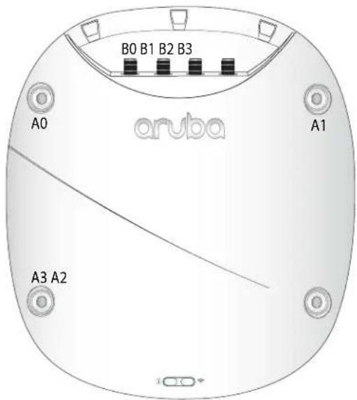
Antenna Connectors
The AP-344 access point supports up to 8 external antennas, which can be attached to the RP-SMA connectors located on the front of the access point. See Figure 3.
The primary antenna ports, labeled A0-A3, correspond with the radio chains 0, 1, 2, and 3. This set of antennas can be used in dual-radio mode (dual band, diplexed), for either upper or lower 5GHz channels in dual-5GHz mode.
The secondary antenna ports, labeled B0-B3, correspond with radio chains 0, 1, 2, and 3. This set if antennas can be used for either upper or lower 5GHz channels in dual-5GHz mode, but are unable to operate in dual-radio mode. These connectors are located beneath a removable plate on the front cover of the device.
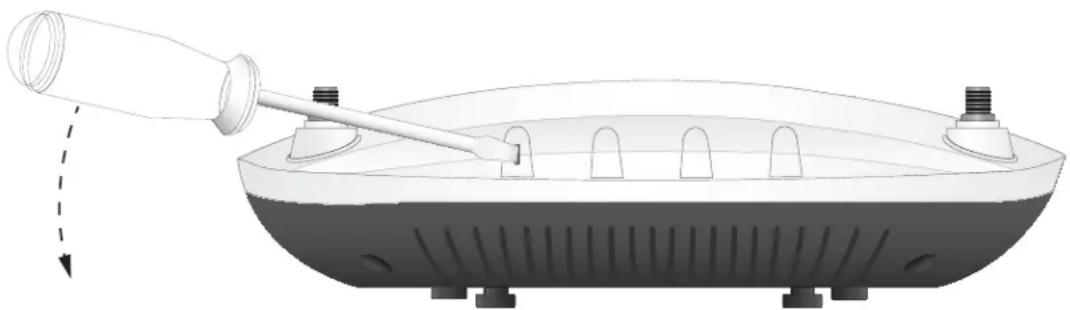
Figure 2 Opening the antenna cover of the AP-344
natural_image
Diagram of a syringe-like device with a pointed tip and base, showing internal components and airflow direction (no text or symbols)To remove the cover, insert a flathead screwdriver into the slotted rubber bushing located on the top edge of the access point, then use the screwdriver to pry off the cover. See Figure 2.
To determine which external antennas are compatible with this device, refer to the product data sheet at www.arubanetworks.com.
Figure 3 Aruba AP-344 antenna ports
External antennas for this device must be installed by an Aruba Certified Mobility Professional (ACMP) or other Aruba-certified technician, using manufacturer-approved antennas only.
The Equivalent Isotropically Radiated Power (EIRP) levels for all external antenna devices must not exceed the regulatory limit set by the host country/domain.
Installers are required to record the antenna gain for this device in the system management software.

Figure 4 Aruba 340 Series (rear view)
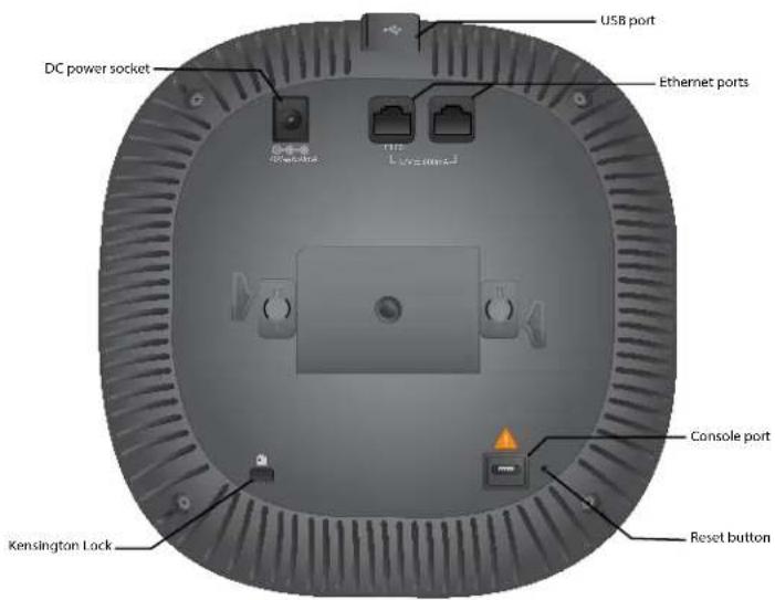
Console Port
The 5-pin Micro-B connector located on the bottom of this device. Use an AP-CBL-SERU cable for direct management of
this device when connected to a laptop or serial console. For port pin-out details, refer to Figure 5.
Figure 5 Micro-B Port Pin-out
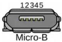
1: NC
2: RXD
3: TXD
4: GND
5: GND
Ethernet Ports
The Aruba 340 Series access point is equipped with two Ethernet ports (E0 and E1) located on the back of the device shown in Figure 4.
E0 port: 100/1000/2500BaseT auto-sensing MDI/MDX wired RJ45 network connectivity port
E1 port: 100/1000BaseT auto-sensing MDI/MDX wired RJ45 network connectivity port
Both ports are compliant with 802.3ab 1000BaseT Gigabit Ethernet standard, while E0 also supports both NBase-T and 802.3bz standards for 2.5bps Ethernet. Both ports support 802.3at and 802.3af to accept power from a POE source, such as a PoE midspan injector, or a network controller.
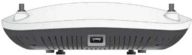
USB Interface
The side of this access point is equipped with a USB-A port that is compatible with cellular modems. When active, this port can supply up to 5W/1A to a connected device. See Figure 6.
Figure 6 Aruba AP-344 (side view)
natural_image
Illustration of a smart home control device with ventilation slots and ports (no text or symbols)Push Button
The push button located on the back-right corner of the device can be used to reset the access point to factory default settings or toggle the LED display.
• To reset the access point to factory default settings:
- Press and hold the push button using a small, narrow object, such as a paperclip.
- Power-on the access point without releasing the push button. The System Status LED will flash within 5 seconds.
- Release the push button.
The system status LED will flash again within 15 seconds indicating that the reset is completed. The access point will now continue to boot with the factory default settings.
• To turn off/on the LED display:
During the normal operation of the access point, press and release the push button using a small, narrow object, such as a paperclip.
Power
Aruba 340 Series access points accept Power over Ethernet (PoE-in) from IEEE 802.3at and 802.3af sources. This can be done by linking either the E0 or E1 port to power sourcing equipment, such as a PoE midspan injector, or network controller providing PoE via Ethernet cable.
If both Ethernet ports are used to draw power from two PoE sources simultaneously, the access point will draw from the more capable power source (prioritizing 802.3at over 802.3af), while continuing to draw a minimal current from the secondary source. In the event that the primary power source fails, the access point will switch to the secondary source for a hitless failover. When both PoE sources are equally capable, the source connected to the E0 port is prioritized.
Alternatively, an AP-AC-48V36C AC-to-DC adapter (sold separately) can be used to power the access point.
If the access point is connected to both DC and PoE sources simultaneously, the device will draw power from the DC source, while continuing to draw a minimal current from the PoE source. In the event that the DC power source fails, the access point will switch to the PoE source for a hitless failover.
The Intelligent Power Monitoring (IPM) feature may also be used to manage the power consumption preferences for this
device. When enabled, the user may enable/disable power restrictions for the access point using Aruba's AP management software.
For details about maximum power consumption levels and operational restrictions for power sourcing modes, refer to Table 3.
Table 3 Power Sourcing Modes
| Power Source IPM | Max Power Consumption | Restrictions |
| DC n/a 28.8W No restrictions, all capabilities available | ||
| PoE 802.3at disabled 25.1W USB disabled* | ||
| PoE 802.3at enabled 25.5W All capabilities available (features may be disabled with IPM configuration) | ||
| PoE 802.3af disabled 13.5W USB disabled*, one Ethernet port disabled, both radios operate in 2x2 mode | ||
| PoE 802.3af enabled 13.5W All capabilities available (features may be disabled with IPM configuration) | ||
* These restriction may be overridden using Aruba's AP management software.
Before You Begin
Refer to the sections below before beginning the installation process.

FCC Statement: Improper termination of access points installed in the United States configured to non-US model controllers will be in violation of the FCC grant of equipment authorization. Any such willful or intentional violation may result in a requirement by the FCC for immediate termination of operation and may be subject to forfeiture (47 CFR 1.80).
Pre-Installation Checklist
Before installing your 340 Series access point, be sure that you have the following:
- Cat5E UTP cable with network access installed in the wall box
- DC power cable
One of the following network services:
• Aruba Discovery Protocol (ADP)
• DNS server with an "A" record
• DHCP Server with vendor-specific options

Aruba Networks, Inc., in compliance with governmental requirements, has designed the 340 Series access points so that only authorized network administrators can change the settings. For more information about access point configuration, refer to the Access Point Software Quick Start Guide.
Identifying Specific Installation Locations
This access point should be oriented vertically, with rubber pads facing downward to facilitate maximum antenna gain. Use the access point placement map generated by Aruba RF Plan software application to determine the proper installation location(s). Each location should be as close as possible to the center of the intended coverage area and should be free from obstructions or obvious sources of interference. These RF absorbers/reflectors/interference sources will impact RF propagation and should be accounted for during the planning phase and adjusted for in RF plan.

Use of this equipment adjacent to or stacked with other equipment should be avoided because it could result in improper operation. If such use is necessary, this equipment and the other equipment should be observed to verify that they are operating normally.
Identifying Known RF Absorbers/Reflectors/Interference Sources
Identifying known RF absorbers, reflectors, and interference sources while in the field during the installation phase is critical. Make sure that these sources are taken into consideration when you attach an access point to its fixed location. RF absorbers include:
- Cement/concrete—Old concrete has high levels of water dissipation, which dries out the concrete, allowing for potential RF propagation. New concrete has high levels of water concentration in the concrete, blocking RF signals.
• Natural Items—Fish tanks, water fountains, ponds, and trees
- Brick
RF reflectors include:
- Metal Objects—Metal pans between floors, rebar, fire doors, air conditioning/heating ducts, mesh windows, blinds, chain link fences (depending on aperture size), refrigerators, racks, shelves, and filing cabinets.
- Do not place an access point between two air conditioning/heating ducts. Make sure that access points are placed below ducts to avoid RF disturbances.
RF interference sources include:
- Microwave ovens and other 2.4 or 5 GHz objects (such as cordless phones)
- Cordless headset such as those used in call centers or lunch rooms

Portable RF communications equipment (including peripherals such as antenna cables and external antennas) should be used no closer than 30 cm (12 inches) to any part of the access point. Otherwise, degradation of the performance of this equipment could result.

RF Radiation Exposure Statement: This equipment complies with RF radiation exposure limits. This equipment should be installed and operated with a minimum distance of 13.78 inches (35cm) between the radiator and your body for 2.4 GHz and 5 GHz operations. This transmitter must not be co-located or operating in conjunction with any other antenna or transmitter.
Access Point Installation
The 340 Series ships with two ceiling rail adapters for 9/16" and 15/16" ceiling rails. Additional wall mount adapters and ceiling rail adapters for other rail styles are available as accessory kits.

All Aruba access points should be professionally installed by an Aruba-Certified Mobility Professional (ACMP). The installer is responsible for ensuring that grounding is available and meets applicable national and electrical codes. Failure to properly install this product may result in physical injury and/or damage to property.
The installer is responsible for securing the access point onto the ceiling tile rail in accordance with the steps below. Failure to properly install this product may result in physical injury and/or damage to property.

Use of accessories, transducers and cables other than those specified or provided by the manufacturer of this equipment could result in increased electromagnetic emissions or decreased electromagnetic immunity of this equipment and result in improper operation.
Using the Ceiling Rail Adapter
- Pull the necessary cables through a prepared hole in the ceiling tile near where the access point will be placed.
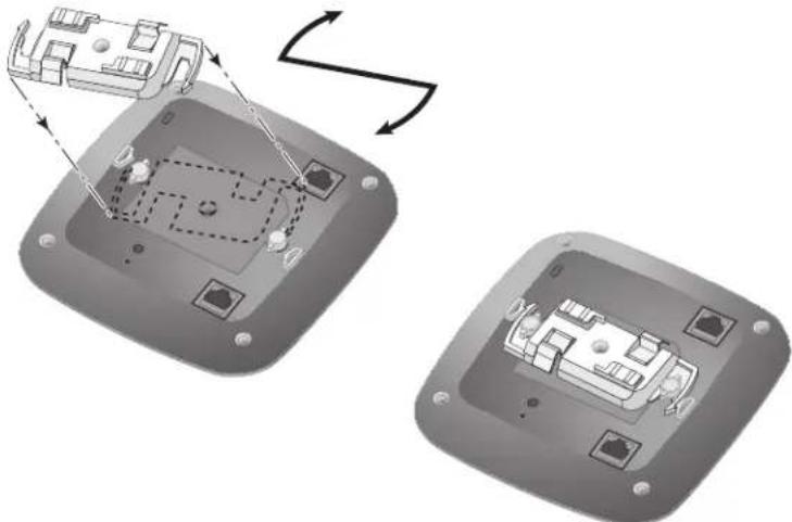
- Place the adapter against the back of the access point with the adapter at an angle of approximately 30 degrees to the tabs (see Figure 7).
- Twist the adapter clockwise until it snaps into place in the tabs (see Figure 7).
Figure 7 Attaching the Ceiling Rail Adapter
natural_image
Diagram showing two views of a device's internal components with arrows indicating rotation or assembly (no text or symbols present)- If necessary, connect the console cable to the console port on the back of the access point.
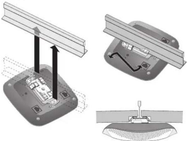
- Hold the access point next to the ceiling tile rail with the ceiling tile rail mounting slots at approximately a 30-degree angle to the ceiling tile rail (see Figure 8). Make sure that any cable slack is above the ceiling tile.
- Pushing toward the ceiling tile, rotate the access point clockwise until the device clicks into place on the ceiling tile rail.
Figure 8 Mounting the Access Point
natural_image
Technical illustration of a mechanical assembly with three views: top view showing structural beams, middle view showing internal components, and bottom view showing a tool (no text or symbols present)- For the AP-344, install the external antennas onto the antenna connectors on front of the access point by screwing them clockwise into place. Once attached to the access point, position the antennas as needed.
Connecting Required Cables
Install cables in accordance with all applicable local and national regulations and practices.
Software
For instructions on choosing operating modes and initial software configuration, refer to the most current version of the
Access Point Software Quick Start Guide.

Aruba access points are classified as radio transmission devices, and are subject to government regulations of the host country. The network administrator(s) is/are responsible for ensuring that configuration and operation of this equipment is in compliance with their country's regulations. For a complete list of approved channels in your country, refer to the Aruba Downloadable Regulatory Table at support.arubanetworks.com.
Verifying Post-Installation Connectivity
The integrated LED on the access point can be used to verify that the access point access point is receiving power and initializing successfully (see Table 1 and Table 2). Refer to the Access Point Software Quick Start Guide for further details on verifying post-installation network connectivity.
Environmental Specifications
For additional specifications on this product, please refer to the product data sheet at www.arubanetworks.com/safety_addendum.
Environmental
- Operating:
■ Temperature: 0°C to +50°C (+32°F to +122°F)
■ Humidity: 5% to 93% non-condensing
• Storage and transport:
■ Temperature: -40^ to +70^ ( -40^ to +158^ )
■ Humidity: 5% to 93% non-condensing

For indoor use only. The access point, AC adapter, and all connected cables are not designed for outdoor use.
Medical
- Equipment not suitable for use in the presence of flammable mixtures.
- Connect to only IEC 60950-1 or IEC 60601-1 certified products and power sources. The end user is responsible for the resulting medical system complies with the requirements of IEC 60601-1.
- Wipe with a dry cloth, no additional maintenance required.
- No serviceable parts, the unit must be sent back to the manufacturer for repair.
No modifications are allowed without Aruba approval.

This device is intended for indoor use in professional healthcare facilities.
Proper Disposal of Aruba Equipment
Dispose of Aruba products per local regulation. For the most current information about Global Environmental Compliance and Aruba products, see our website at www.arubanetworks.com.

The expected service life for this device is 10 years.
Waste of Electrical and Electronic Equipment

Aruba products at end of life are subject to separate collection and treatment in the EU Member States, Norway, and Switzerland and therefore are marked with the symbol shown at the left (crossed-out wheelie bin). The treatment applied at end of life of these products in these countries shall comply with the applicable national laws of countries implementing Directive 2012/19/EU of the European Parliament and of the Council on Waste Electrical and Electronic Equipment (WEEE).

Changes or modifications to this unit not expressly approved by the party responsible for compliance could void the user's authority to operate this equipment.
Regulatory Information
The regulatory model numbers (RMN) for the 340 Series access points are:
AP-344 RMN: APIN0344
AP-345 RMN: APIN0345
The equipment name for the 340 Series access points is 802.11 Wireless Access Point with Bluetooth BLE.

Compliance is based on the use of Aruba approved accessories. Refer to the buyer's guide for this access point at www.arubanetworks.com.
Brazil
This Class B digital apparatus meets all of the requirements of the Canadian Interference-Causing Equipment
Regulations.
In accordance with Industry Canada regulations, this radio transmitter and receiver may only be used with an antenna, the maximum type and gain of which must be approved by Industry Canada. To reduce potential radio interference, the type of antenna and its gain shall be chosen so that the equivalent isotropic radiated power (EIRP) does not exceed the values necessary for effective communication.
This device complies with Industry Canada's license-exempt RSS regulations. Operation of this device is subject to the following two conditions: (1) this device may not cause interference, and (2) this device must accept any interference, including interference that may cause undesired operation.
When operated in the 5.15 to 5.25 GHz frequency range, this device is restricted to indoor use to reduce the potential for harmful interference with co-channel Mobile Satellite Systems.
This radio transmitter model APIN0344 has been approved by Industry Canada to operate with the antenna types listed in the online ordering guide (link provided below) with the maximum permissible gain indicated. Antenna types not included in this list, having a greater gain than the maximum gain indicated for that type, are strictly prohibited for use with this device. http://www.arubanetworks.com/assets/og/OG_AP-340Series.pdf
Aruba products also comply with China environmental declaration requirements and are packaged with the "EFUP25" label shown below.
有毒有害物质声明
Hazardous Materials Declaration
| 部件名称(Parts) | 有毒有害物质或元素(Hazardous Substance) | |||||
| 铅(Fb) | 汞(Hg) | 镉(Cd) | 六价铬( Cr^n ) | 多溴联苯(PBB) | 多溴二苯醚(PBDE) | |
| 电路板(PCA Boards) | × | ○ | ○ | ○ | ○ | ○ |
| 机械组件(Mechanical Sub-Assemblies) | × | ○ | ○ | ○ | ○ | ○ |
| ○:表示该有毒有害物质在该部件所有均质材料中的含量均在SJ/T11363-2006标准规定的限量要求以下。Indicates that the concentration of the hazardous substance in all homogeneous materials in the parts is below the relevant threshold of the SJ/T11363-2006 standard.×:表示该有毒有害物质至少在该部件的某一均质材料中的含量超出SJ/T11363-2006标准规定的限量要求。Indicates that the concentration of the hazardous substance of at least one of all homogeneous materials in the parts is above the relevant threshold of the SJ/T11363-2006 standard.对销售之日的所售产品,本表显示,供应链的电子信息产品可能包含这些物质。This table shows where these substances may be found in the supply chain of electronic information products, as of the date of sale of the enclosed product. | ||||||
The Environment-Friendly Use Period (EFUP) for all enclosed products and their parts are per the symbol shown here. The Environment-Friendly Use Period is valid only when the product is operated under the conditions defined in the product manual.

Taiwan RoHS
Table-APIN0344/APIN0345-20180124
無線接收盒 : 802.11 Wireless Access Point with Bluetooth BLE
Type Designation: APIN0344_345
台灣限用物質含有情況標示
The Declaration of Conformity made under RED Directive 2014/53/EU is available for viewing at support.arubanetworks.com, then navigate to the Declarations of Conformity > Access Point folder, then select the document that corresponds to your device's model number as it is indicated on the packaging of this product. This radio transmitter model APIN0344 has been approved to operate with the antenna types listed in the online ordering guide (link provided below) with the maximum permissible gain indicated. Antenna types not included in this list, having a greater gain than the maximum gain indicated for that type, are strictly prohibited for use with this device. http://www.arubanetworks.com/assets/og/OG_AP-340Series.pdf
Wireless Channel Restrictions
5150-5350MHz band is limited to indoor only in the following countries; Austria (AT), Belgium (BE), Bulgaria (BG), Croatia (HR), Cyprus (CY), Czech Republic (CZ), Denmark (DK), Estonia (EE), Finland (FI), France (FR), Germany (DE), Greece (GR), Hungary (HU), Iceland (IS), Ireland (IE), Italy (IT), Latvia (LV), Liechtenstein (LI), Lithuania (LT), Luxembourg (LU), Malta (MT), Netherlands (NL), Norway (NO), Poland (PL), Portugal (PT), Romania (RO), Slovakia (SK), Slovenia (SL), Spain (ES), Sweden (SE), Switzerland (CH), Turkey (TR), United Kingdom (UK).
Frequency Range MHz Max EIRP
| 2402-2480 9 dbm |
| 2412-2472 20 dBm |
| 5150-5250 23 dBm |
| 5250-5350 23 dBm |
Frequency Range MHz Max EIRP
5470-5725 30 dBm
5725-5850 N/A for EU
India
This product complies with RoHS requirements as prescribed by E-Waste (Management & Handling) Rules, governed by the Ministry of Environment & Forests, Government of India.
Korean
Type-Approval No. ESD-1816672C

NTC
Type-Approval No. ESD-1816670C
Singapore
Complies with
IDA Standards
DB100427
This equipment has been tested and found to comply with the limits for a Class B digital device, pursuant to Part 15 of the FCC Rules. These limits are designed to provide reasonable protection against harmful interference in a residential installation. This equipment generates, uses, and can radiate radio frequency energy and, if not installed and used in accordance with the instructions, may cause harmful interference to radio communications. However, there is no guarantee that interference will not occur in a particular installation. If this equipment does cause harmful interference to radio or television reception, which can be determined by turning the equipment off and on, the user is encouraged to try to correct the interference by one or more of the following measures: · Reorient or relocate the receiving antenna. · Increase the separation between the equipment and receiver. · Connect the equipment into an outlet on a circuit that is different from that to which the receiver is connected. Consult the dealer or an experienced radio or television technician for help.
Improper termination of access points installed in the United States configured to a non-US model controller is a violation of the FCC grant of equipment authorization. Any such willful or intentional violation may result in a requirement by the FCC for immediate termination of operation and may be subject to forfeiture (47 CFR 1.80).
The network administrator(s) is/are responsible for ensuring that this device operates in accordance with local/regional laws of the host domain.
| Radio Type | Frequency Range | Power (EIRP) | Modulation |
| BLE 2400-2483.5MHz <10dBm GFSK | |||
| 802.11 2400-2483.5MHz 20dBm CCK, OFDM | |||
| 802.11 5150-5250MHz 23dBm OFDM | |||
| 802.11 5250-5350MHz 23dBm OFDM | |||
| 802.11 5500-5700MHz 30dBm OFDM | |||
| 802.11 5725-5850MHz 36dBm OFDM |

NOTE
Actual output power values will depend on national restrictions and the antennas used.
| Complies with: | Emissions - CISPR11/EN55011, Group 1, Class B |
| Immunity: | |
| Electrostatic discharge: | +/-8kV contact/ +/-15kV air |
| Radiated RF EM fields: | 80MHz - 2.7GHz, 3V/m |
| Proximity fields from RF wireless communication equipment: | per Table 9 of the IEC/EN 60601-1-2 |
| RATED power frequency magnetic fields: 30A/m | |
| Electrical Fast Transients: +/-2kV | |
| Surges (line-to-line): +/- 0.5, 1.0 | |
| Surges (line-to-ground): +/- 0.5, 1.0, 2kV | |
| Conducted disturbances induced by RF fields: 0.15MHz-80MHz, 3Vrms | |
| Voltage Dips: 0%, 0.5 cycles, 0%, 1 cycle, 70% 25/30 cycles | |
| Voltage Interruptions: 0% 250/300 cycles |

NOTE
This device has no IEC/EN60601-1-2 essential performance.
Medical
- Equipment not suitable for use in the presence of flammable mixtures.
- Connect to only IEC 60950-1 or IEC 60601-1 3rd edition certified products and power sources. The end user is responsible for the resulting medical system complies with the requirements of IEC 60601-1 3rd edition.
- Wipe with a dry cloth, no additional maintenance required.
- No serviceable parts, the unit must be sent back to the manufacturer for repair.
- No modifications are allowed without Aruba approval.

NOTE
Expected Service Life 10 years. For additional compliance information, refer to the regulatory label on the back of this device.
Contact Aruba
| Main Site http://www.arubanetworks.com | |
| Support Site http://www.support.arubanetworks.com | |
| Airheads Social Forums and Knowledge Base | http://community.arubanetworks.com/ |
| North America Telephone 1-800-943-4526 (toll free)1-408-754-1200 | |
| International Telephone | http://arubanetworks.com/support-services/contact-support/ |
| Software Licensing Site http://hpe.com/networking/support | |
| End-of-Life Information | http://arubanetworks.com/support-services/end-of-life/ |
| Security Incident Response Team (SIRT) | Site: http://www.arubanetworks.com/support-service/security-bulletins/Email: sirt@arubanetworks.com |
Copyright
© Copyright 2018 Hewlett Packard Enterprise Development LP
Open Source Code
This product includes code licensed under the GNU General PublicLicense, the GNU Lesser General Public License, and/or certain other open source licenses.
A complete machine-readable copy of the source code corresponding to such code is available upon request. This offer is valid to anyone in receipt of this information and shall expire three years following the date of the final distribution of this product version by Hewlett Packard Enterprise Company.
To obtain such source code, send a check or money order in the amount of US \$10.00 to:
Hewlett Packard Enterprise Company
Attn: General Counsel
3000 Hanover Street
Palo Alto, CA 94304
USA
Warranty
This hardware product is protected by an Aruba warranty. For more details visit www.hpe.com/us/en/support.html